EP1607688A2 - Solarthermische Heizungsanlage - Google Patents
Solarthermische Heizungsanlage Download PDFInfo
- Publication number
- EP1607688A2 EP1607688A2 EP05011983A EP05011983A EP1607688A2 EP 1607688 A2 EP1607688 A2 EP 1607688A2 EP 05011983 A EP05011983 A EP 05011983A EP 05011983 A EP05011983 A EP 05011983A EP 1607688 A2 EP1607688 A2 EP 1607688A2
- Authority
- EP
- European Patent Office
- Prior art keywords
- solar
- heating
- storage tank
- sensor
- heater
- Prior art date
- Legal status (The legal status is an assumption and is not a legal conclusion. Google has not performed a legal analysis and makes no representation as to the accuracy of the status listed.)
- Withdrawn
Links
Images
Classifications
-
- F—MECHANICAL ENGINEERING; LIGHTING; HEATING; WEAPONS; BLASTING
- F24—HEATING; RANGES; VENTILATING
- F24D—DOMESTIC- OR SPACE-HEATING SYSTEMS, e.g. CENTRAL HEATING SYSTEMS; DOMESTIC HOT-WATER SUPPLY SYSTEMS; ELEMENTS OR COMPONENTS THEREFOR
- F24D19/00—Details
- F24D19/10—Arrangement or mounting of control or safety devices
- F24D19/1006—Arrangement or mounting of control or safety devices for water heating systems
- F24D19/1009—Arrangement or mounting of control or safety devices for water heating systems for central heating
- F24D19/1042—Arrangement or mounting of control or safety devices for water heating systems for central heating the system uses solar energy
-
- F—MECHANICAL ENGINEERING; LIGHTING; HEATING; WEAPONS; BLASTING
- F24—HEATING; RANGES; VENTILATING
- F24S—SOLAR HEAT COLLECTORS; SOLAR HEAT SYSTEMS
- F24S50/00—Arrangements for controlling solar heat collectors
-
- Y—GENERAL TAGGING OF NEW TECHNOLOGICAL DEVELOPMENTS; GENERAL TAGGING OF CROSS-SECTIONAL TECHNOLOGIES SPANNING OVER SEVERAL SECTIONS OF THE IPC; TECHNICAL SUBJECTS COVERED BY FORMER USPC CROSS-REFERENCE ART COLLECTIONS [XRACs] AND DIGESTS
- Y02—TECHNOLOGIES OR APPLICATIONS FOR MITIGATION OR ADAPTATION AGAINST CLIMATE CHANGE
- Y02B—CLIMATE CHANGE MITIGATION TECHNOLOGIES RELATED TO BUILDINGS, e.g. HOUSING, HOUSE APPLIANCES OR RELATED END-USER APPLICATIONS
- Y02B10/00—Integration of renewable energy sources in buildings
- Y02B10/20—Solar thermal
-
- Y—GENERAL TAGGING OF NEW TECHNOLOGICAL DEVELOPMENTS; GENERAL TAGGING OF CROSS-SECTIONAL TECHNOLOGIES SPANNING OVER SEVERAL SECTIONS OF THE IPC; TECHNICAL SUBJECTS COVERED BY FORMER USPC CROSS-REFERENCE ART COLLECTIONS [XRACs] AND DIGESTS
- Y02—TECHNOLOGIES OR APPLICATIONS FOR MITIGATION OR ADAPTATION AGAINST CLIMATE CHANGE
- Y02B—CLIMATE CHANGE MITIGATION TECHNOLOGIES RELATED TO BUILDINGS, e.g. HOUSING, HOUSE APPLIANCES OR RELATED END-USER APPLICATIONS
- Y02B10/00—Integration of renewable energy sources in buildings
- Y02B10/70—Hybrid systems, e.g. uninterruptible or back-up power supplies integrating renewable energies
-
- Y—GENERAL TAGGING OF NEW TECHNOLOGICAL DEVELOPMENTS; GENERAL TAGGING OF CROSS-SECTIONAL TECHNOLOGIES SPANNING OVER SEVERAL SECTIONS OF THE IPC; TECHNICAL SUBJECTS COVERED BY FORMER USPC CROSS-REFERENCE ART COLLECTIONS [XRACs] AND DIGESTS
- Y02—TECHNOLOGIES OR APPLICATIONS FOR MITIGATION OR ADAPTATION AGAINST CLIMATE CHANGE
- Y02E—REDUCTION OF GREENHOUSE GAS [GHG] EMISSIONS, RELATED TO ENERGY GENERATION, TRANSMISSION OR DISTRIBUTION
- Y02E10/00—Energy generation through renewable energy sources
- Y02E10/40—Solar thermal energy, e.g. solar towers
Definitions
- the invention relates to a solar thermal heating system according to the preamble of the claim 1.
- Such known solar thermal heating systems are used for hot water and / or building heating used.
- Solar thermal heating systems can be seen over the year the energy needs for do not completely cover the water heating and / or heating of a building. For this reason, solar thermal heating systems must be replaced by conventional, ie especially fossil or heat pump based heating systems become.
- the heating control of the conventional heating system measures for this via a Temperature sensor, the temperature of the stored water in a storage tank and starts when falling below a target temperature, the conventional reheating.
- Represents the heating control of the solar thermal heating system compared to the conventional Heating control is a self-sufficient system, as with different manufacturers the case is, so in practice is a communication of the solar heating control and the conventional heating control is not given. Thus, it may be undesirable too a simultaneous heating of the solar thermal and conventional heating system come.
- the heating is thus parallel with conventional energy, although sufficient solar energy is available.
- the lack of communication between solar and conventional heating control therefore results in giving away solar energy and an energy disadvantage compared to heating systems, where the solar and conventional heating control are integrated exists.
- the invention is based on the object, a solar thermal heating system of the type mentioned in such a way that even if missing Communication between the solar and conventional heating control an undesirable Parallel operation of the associated heating systems is avoided.
- the term "conventional heating device” includes in the following with reference to the description of the invention, any type of heating devices, their heat generation not based on the timely implementation of solar energy.
- the solar heater can be a liquid, eg. As water or storage oil, or also a non-liquid medium, for. As paraffin serve.
- the essence of the invention is that with sufficient solar energy of the Storage tank temperature sensor by means of the sensor heater so thermally is influenced that the conventional heater, a higher temperature of Water and thus no need to heat by the conventional heater is reflected.
- the conventional heating device can thus without need direct intervention in their regulation by the external thermal influence by means of the Sensor heater shut down by the solar thermal heating system become.
- the control of the sensor heater takes place here by the temperature control device the solar thermal heating system. With sufficient solar energy is thus given away no solar energy and thus an energetic Disadvantage avoided.
- due to the external thermal influence does not have be intervened directly in the conventional heating device, making it in particular does not void the manufacturer's warranty in the conventional heater comes.
- the temperature control device processes the analog-digital converted Measurement signals and controls the sensor heater.
- the digital Control and control unit enables comfortable and flexible control the sensor heater.
- the solar sensor according to claim 3 allows at any time an accurate measurement of solar radiation and thus an assessment of the solar energy input.
- a Solar radiation measurement is a measurement of the temperature of a solar collector of Solar heater possible.
- a corresponding temperature sensor can also be removed be arranged by the solar heater.
- the control and regulation unit can control the solar heater carry out.
- the solar storage tank temperature sensor allows the solar thermal Heating system a separate measurement of the water temperature in the storage tank. With this temperature signal, the solar thermal heating system by means of Temperature control device, a control of the water temperature in the storage tank carry out.
- the heating jacket according to claim 5 allows the sensor heater an efficient and spatially uniform heating of the storage tank temperature sensor and thus a corresponding influence on the sensor value of the storage tank temperature sensor the conventional heater.
- the heating jacket according to claim 6 can be heated effectively and easily controllable.
- a Protective or immersion sleeve provided.
- a protective sleeve according to claim 8 is advantageous.
- the sensor heater can thus be effective z. B. protected against short circuits.
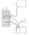
- a solar thermal heating system designated as a whole by 1 comprises a solar heating device 2 for heating a present in a storage container 3 amount Water 4.
- the solar thermal heating system 1 acts with a fossil heater 5 together.
- the fossil heater 5 includes a boiler, not shown for oil, gas or solid fuels, heat pumps and a heating control.
- a storage tank temperature sensor 6 is disposed associated with the fossil heater 5 is in signal connection.
- the solar thermal heating system 1 furthermore has a temperature control device 7 with a digital control and control unit 8.
- the digital regulatory and Control unit 8 is in signal communication with a solar sensor 9 for measuring the Solar radiation, a solar storage tank temperature sensor 10 for measuring the Water temperature in the storage tank 3 and a sensor heater 11.
- the sensor heater 11 includes a surrounding the storage tank temperature sensor 6 and electrically heatable heating sleeve 12 and a protective sleeve 13, the heating jacket 12 and the storage tank temperature sensor 6 inside the storage tank 3 watertight surrounds.
- the solar sensor 9 is in close proximity to the solar heater 2, ideally located on the roof of a building.
- the solar storage tank temperature sensor 10 is analogous to the storage tank temperature sensor 6 arranged in the interior of the storage container 3. An arrangement elsewhere, z. B. at a suitable location in the piping system or in a solar thermal heating system 1 associated second storage tank is also possible. Between the solar thermal Heating system 1 and the heating control of the fossil heater 5 there is no signal connection.
- the operation of the solar thermal heating system 1 in cooperation with the fossil heater 5 described in more detail.
- the analogue measurement signal of the solar sensor 9 is controlled by an analog-to-digital converter of digital control and Control unit 8 provided as digital readings.
- the digital regulatory and Control unit 8 recognizes from the digital measurements that sufficient solar energy is available.
- a signal for heating the storage tank temperature sensor is sent to the sensor heater 11 6, which is in signal communication with the fossil heater 5 stands, given.
- the electrically heatable heating jacket 12 is driven, surrounding the storage tank temperature sensor 6 and a protective sleeve 13 is received waterproof in the interior of the storage container 3.
- the in thermal contact heated with the storage tank temperature sensor 6 heating jacket 12 is heated the storage tank temperature sensor 6 until the fossil heater 5 is a temperature of the water 4 is reflected, which is above the desired set temperature the fossil heater 5 is located.
- the fossil heater 5 is now inoperative does not heat up. If the temperature of the water 4 in the storage tank 3 drops below a desired setpoint temperature, this is the solar storage tank temperature sensor 10th detected and passed to the temperature control device 7.
- the analog temperature signal is in turn converted to digital readings by an analog-to-digital converter and the digital control and control unit 8 provided.
- These recognizes the need to reheat the stored water 4 and controls the solar heater 2 such that the present in the storage tank 3 water 4 is heated. This can be done by starting a circulation pump, which in the storage tank 3 present water 4 through hot tubes in the solar heater. 2 inflated. This takes place until the stored water 4 in the storage container 3 on the desired setpoint temperature is heated and the solar storage tank temperature sensor 10th recognizes this and passes it on to the digital control and control unit 8.
- the temperature control device 7 Detects the temperature control device 7 from the measured values of the solar sensor 9 and of solar storage tank temperature sensor 10 that not enough solar energy available is the temperature control device 7 to the sensor-heater 11 is the Signal that the heating jacket 12 is no longer to be electrically heated. thereupon cools the heating jacket 12 and the storage tank temperature sensor 6 measures again the actual temperature of the water 4. Represents the storage tank temperature sensor Now note that the water temperature is below the desired setpoint temperature is located, the heating control of the fossil heater 5 starts the reheating of the water 4 in the storage tank 3. This is again until the desired Target temperature of the water 4 is reached in the storage tank 3. The reheating of the fossil Heating device 5 can thus be targeted by the solar thermal heating system 1 be suppressed, so that the existing solar energy can be fully utilized can.
Landscapes
- Engineering & Computer Science (AREA)
- Life Sciences & Earth Sciences (AREA)
- Sustainable Development (AREA)
- Sustainable Energy (AREA)
- Physics & Mathematics (AREA)
- Thermal Sciences (AREA)
- Chemical & Material Sciences (AREA)
- Combustion & Propulsion (AREA)
- Mechanical Engineering (AREA)
- General Engineering & Computer Science (AREA)
- Heat-Pump Type And Storage Water Heaters (AREA)
Abstract
Description
Claims (8)
- Solarthermische Heizungsanlage (1) umfassendeine Solar-Heizvorrichtung (2) zum Aufheizen eines in einem Speicherbehälter (3) vorliegenden Temperaturspeichermediums (4), undeine Temperatur-Regelvorrichtung (7) zur Zusammenwirkung mit einem Speicherbehälter-Temperatursensor (6) einer konventionellen Heizvorrichtung (5), gekennzeichnet durch eine Sensor-Heizvorrichtung (11), welchemit dem Speicherbehälter-Temperatursensor (6) zur Beheizung von diesem in Wärmekontakt bringbar ist, undmit der Temperatur-Regelvorrichtung (7) in Signalverbindung steht.
- Solarthermische Heizungsanlage nach Anspruch 1, dadurch gekennzeichnet, dass die Temperatur-Regelvorrichtung (7) eine digitale Regelungs- und Steuerungseinheit (8) aufweist.
- Solarthermische Heizungsanlage nach Anspruch 2, dadurch gekennzeichnet, dass die Solar-Heizvorrichtung (2) einen mit der Regelungs- und Steuerungseinheit (8) verbundenen Solar-Sensor (9) zur Messung der Sonneneinstrahlung aufweist.
- Solarthermische Heizungsanlage nach Anspruch 2 oder 3, dadurch gekennzeichnet, dass die Solar-Heizvorrichtung (2) einen mit der Regelungs- und Steuerungseinheit (8) verbundenen Solar-Speicherbehälter-Temperatursensor (10) zur Messung der Wassertemperatur im Speicherbehälter (3) aufweist.
- Solarthermische Heizungsanlage nach einem der vorangegangenen Ansprüche, dadurch gekennzeichnet, dass die Sensor-Heizvorrichtung (11) eine Heizmanschette (12) aufweist.
- Solarthermische Heizungsanlage nach Anspruch 5, dadurch gekennzeichnet, dass die Heizmanschette (12) elektrisch beheizbar ist.
- Solarthermische Heizungsanlage nach einem der vorangegangenen Ansprüche, dadurch gekennzeichnet, dass die Sensor-Heizvorrichtung (11) eine Schutzhülse (13) zur Aufnahme der Heizmanschette (12) und des Speicherbehälter-Temperatursensors (6) aufweist.
- Solarthermische Heizungsanlage nach Anspruch 7, dadurch gekennzeichnet, dass die Heizmanschette (12) und der Speicherbehälter-Temperatursensor (6) wasserdicht von der Schützhülse (13) umgeben sind.
Applications Claiming Priority (2)
| Application Number | Priority Date | Filing Date | Title |
|---|---|---|---|
| DE102004029392 | 2004-06-17 | ||
| DE102004029392A DE102004029392A1 (de) | 2004-06-17 | 2004-06-17 | Solarthermische Heizungsanlage |
Publications (2)
| Publication Number | Publication Date |
|---|---|
| EP1607688A2 true EP1607688A2 (de) | 2005-12-21 |
| EP1607688A3 EP1607688A3 (de) | 2010-12-29 |
Family
ID=34980340
Family Applications (1)
| Application Number | Title | Priority Date | Filing Date |
|---|---|---|---|
| EP05011983A Withdrawn EP1607688A3 (de) | 2004-06-17 | 2005-06-03 | Solarthermische Heizungsanlage |
Country Status (2)
| Country | Link |
|---|---|
| EP (1) | EP1607688A3 (de) |
| DE (1) | DE102004029392A1 (de) |
Families Citing this family (2)
| Publication number | Priority date | Publication date | Assignee | Title |
|---|---|---|---|---|
| DE102022127741B4 (de) * | 2022-10-20 | 2025-03-06 | Peter Brecklinghaus | Nachrüstsatz für ein bereits vorhandenes Zentralheizungssystem und ein Verfahren zum Nachrüsten eines bereits vorhandenen Zentralheizungssystems mittels eines Nachrüstsatzes |
| DE102022127744B4 (de) * | 2022-10-20 | 2025-03-06 | Peter Brecklinghaus | Zentralheizungssystem und Verfahren zum Betrieb und/oder zur Steuerung und/oder zur Regelung eines Zentralheizungssystems |
Family Cites Families (7)
| Publication number | Priority date | Publication date | Assignee | Title |
|---|---|---|---|---|
| DE2814243A1 (de) * | 1978-04-03 | 1979-10-11 | Resol Elektronische Regelungen | Elektronische regelung fuer mehrspeicher-sonnenheizsysteme |
| FR2428794A1 (fr) * | 1978-06-12 | 1980-01-11 | Saunier Duval | Chauffe-eau a accumulation mixte a energie solaire et energie d'appoint electrique ou autre |
| US5206819A (en) * | 1990-09-06 | 1993-04-27 | Illing Wesley R | Control system for solar heater |
| DE19955976A1 (de) * | 1999-04-23 | 2000-10-26 | Heinz Grueterich | Verfahren zur energieoptimierten Nutzung von Pufferwärmespeichern mit Solaranlage und Primärheizsystem |
| DE19953493C2 (de) * | 1999-11-06 | 2003-12-18 | Ht Helio Tech Gmbh | Solaranlage |
| AT4804U1 (de) * | 2000-12-05 | 2001-11-26 | Tech Alternative Elektronische | Elektronischer regler für heizungs- bzw. solaranlagen |
| DE10130162C1 (de) * | 2001-06-22 | 2003-04-24 | Simon Maier | Nachladesteuerung für einen mit Sonnenenergie beheizten Warmwasserspeicher |
-
2004
- 2004-06-17 DE DE102004029392A patent/DE102004029392A1/de not_active Withdrawn
-
2005
- 2005-06-03 EP EP05011983A patent/EP1607688A3/de not_active Withdrawn
Also Published As
| Publication number | Publication date |
|---|---|
| DE102004029392A1 (de) | 2006-01-05 |
| EP1607688A3 (de) | 2010-12-29 |
Similar Documents
| Publication | Publication Date | Title |
|---|---|---|
| DE7910516U1 (de) | Solarboiler | |
| EP2233858B1 (de) | Warmwasserspeicher mit Sensorsystem | |
| DE2523436B2 (de) | Fluessigkeitskuehlsystem fuer eine brennkraftmaschine | |
| DE102004029392A1 (de) | Solarthermische Heizungsanlage | |
| DE202007008024U1 (de) | Mischeinrichtung zur Einstellung der Warmwassertemperatur | |
| EP3073200A1 (de) | Beheizte hydraulische weiche zur optimierten einbindung von fremdwärme | |
| DE102009051209A1 (de) | Einrichtung zur Temperaturregelung eines Raumes mit mindestens einer mit einem Wärmeträger betriebenen Heizeinrichtung | |
| DE3030565A1 (de) | Heizkessel fuer heizungsanlagen | |
| DE2205358A1 (de) | Überhitzungsschutz an elektrischen Sauna-Aggregaten | |
| DE102019113131A1 (de) | Hochdruckreinigungssystem | |
| DE102005035821B3 (de) | Thermische Solaranlage | |
| DE102013219142B4 (de) | Heizsystem | |
| DE102009034556A1 (de) | Verfahren zur Überwachung des Verschmutzungszustandes eines Wärmetauschers zur Warmwasserbereitung an einem Heizgerät | |
| DE2851212A1 (de) | Schaltung fuer eine warmwasserheizungsanlage | |
| EP4191159A1 (de) | Heizgerät, verfahren zum betreiben eines heizgerätes und verwendung eines bypassventils | |
| DE2730047A1 (de) | Heizeinrichtung unter ausnuetzung der sonnenenergie | |
| DE10143456B4 (de) | Heizgerät und Verfahren zum Steuern und/oder Regeln eines Heizgerätes | |
| DE1952322A1 (de) | Heizkessel,insbesondere fuer elektrische Beheizung | |
| DE202006003334U1 (de) | Vorrichtung zum Erwärmen eines Wärmeträgers einer Heizung und von Brauchwasser | |
| DE19926415C2 (de) | Anordnung zur Kopplung eines Raumheizsystems und eines Brauchwasserspeichers mit einem Solarkollektor | |
| DE8813582U1 (de) | Umlaufwasserheizung | |
| DE3409206A1 (de) | Heizvorrichtung | |
| DE4205562A1 (de) | Verfahren und vorrichtung zum kurzzeitigen schnellaufheizen von warmwasserheizungsanlagen | |
| DE8407711U1 (de) | Heizvorrichtung | |
| DE2402497A1 (de) | Verfahren und anlage zur bereitstellung des waermebedarfs fuer zentralheizungsanlagen |
Legal Events
| Date | Code | Title | Description |
|---|---|---|---|
| PUAI | Public reference made under article 153(3) epc to a published international application that has entered the european phase |
Free format text: ORIGINAL CODE: 0009012 |
|
| AK | Designated contracting states |
Kind code of ref document: A2 Designated state(s): AT BE BG CH CY CZ DE DK EE ES FI FR GB GR HU IE IS IT LI LT LU MC NL PL PT RO SE SI SK TR |
|
| AX | Request for extension of the european patent |
Extension state: AL BA HR LV MK YU |
|
| PUAL | Search report despatched |
Free format text: ORIGINAL CODE: 0009013 |
|
| AK | Designated contracting states |
Kind code of ref document: A3 Designated state(s): AT BE BG CH CY CZ DE DK EE ES FI FR GB GR HU IE IS IT LI LT LU MC NL PL PT RO SE SI SK TR |
|
| AX | Request for extension of the european patent |
Extension state: AL BA HR LV MK YU |
|
| RIC1 | Information provided on ipc code assigned before grant |
Ipc: F24J 2/40 20060101ALI20101122BHEP Ipc: F24D 19/10 20060101AFI20051003BHEP |
|
| AKY | No designation fees paid | ||
| REG | Reference to a national code |
Ref country code: DE Ref legal event code: R108 |
|
| REG | Reference to a national code |
Ref country code: DE Ref legal event code: R108 Effective date: 20110907 |
|
| STAA | Information on the status of an ep patent application or granted ep patent |
Free format text: STATUS: THE APPLICATION IS DEEMED TO BE WITHDRAWN |
|
| 18D | Application deemed to be withdrawn |
Effective date: 20110630 |