EP1607605A1 - Pressure estimating system in the exhaust manifold of a diesel engine and method for calibrating said system - Google Patents
Pressure estimating system in the exhaust manifold of a diesel engine and method for calibrating said system Download PDFInfo
- Publication number
- EP1607605A1 EP1607605A1 EP05300454A EP05300454A EP1607605A1 EP 1607605 A1 EP1607605 A1 EP 1607605A1 EP 05300454 A EP05300454 A EP 05300454A EP 05300454 A EP05300454 A EP 05300454A EP 1607605 A1 EP1607605 A1 EP 1607605A1
- Authority
- EP
- European Patent Office
- Prior art keywords
- pressure
- acquisition
- cylinder
- predetermined
- crankshaft angle
- Prior art date
- Legal status (The legal status is an assumption and is not a legal conclusion. Google has not performed a legal analysis and makes no representation as to the accuracy of the status listed.)
- Granted
Links
Images


Classifications
-
- F—MECHANICAL ENGINEERING; LIGHTING; HEATING; WEAPONS; BLASTING
- F02—COMBUSTION ENGINES; HOT-GAS OR COMBUSTION-PRODUCT ENGINE PLANTS
- F02D—CONTROLLING COMBUSTION ENGINES
- F02D35/00—Controlling engines, dependent on conditions exterior or interior to engines, not otherwise provided for
- F02D35/02—Controlling engines, dependent on conditions exterior or interior to engines, not otherwise provided for on interior conditions
- F02D35/023—Controlling engines, dependent on conditions exterior or interior to engines, not otherwise provided for on interior conditions by determining the cylinder pressure
-
- F—MECHANICAL ENGINEERING; LIGHTING; HEATING; WEAPONS; BLASTING
- F02—COMBUSTION ENGINES; HOT-GAS OR COMBUSTION-PRODUCT ENGINE PLANTS
- F02D—CONTROLLING COMBUSTION ENGINES
- F02D41/00—Electrical control of supply of combustible mixture or its constituents
- F02D41/0002—Controlling intake air
- F02D41/0007—Controlling intake air for control of turbo-charged or super-charged engines
-
- F—MECHANICAL ENGINEERING; LIGHTING; HEATING; WEAPONS; BLASTING
- F02—COMBUSTION ENGINES; HOT-GAS OR COMBUSTION-PRODUCT ENGINE PLANTS
- F02D—CONTROLLING COMBUSTION ENGINES
- F02D41/00—Electrical control of supply of combustible mixture or its constituents
- F02D41/02—Circuit arrangements for generating control signals
- F02D41/14—Introducing closed-loop corrections
- F02D41/1438—Introducing closed-loop corrections using means for determining characteristics of the combustion gases; Sensors therefor
- F02D41/1444—Introducing closed-loop corrections using means for determining characteristics of the combustion gases; Sensors therefor characterised by the characteristics of the combustion gases
- F02D41/1448—Introducing closed-loop corrections using means for determining characteristics of the combustion gases; Sensors therefor characterised by the characteristics of the combustion gases the characteristics being an exhaust gas pressure
- F02D41/145—Introducing closed-loop corrections using means for determining characteristics of the combustion gases; Sensors therefor characterised by the characteristics of the combustion gases the characteristics being an exhaust gas pressure with determination means using an estimation
-
- Y—GENERAL TAGGING OF NEW TECHNOLOGICAL DEVELOPMENTS; GENERAL TAGGING OF CROSS-SECTIONAL TECHNOLOGIES SPANNING OVER SEVERAL SECTIONS OF THE IPC; TECHNICAL SUBJECTS COVERED BY FORMER USPC CROSS-REFERENCE ART COLLECTIONS [XRACs] AND DIGESTS
- Y02—TECHNOLOGIES OR APPLICATIONS FOR MITIGATION OR ADAPTATION AGAINST CLIMATE CHANGE
- Y02T—CLIMATE CHANGE MITIGATION TECHNOLOGIES RELATED TO TRANSPORTATION
- Y02T10/00—Road transport of goods or passengers
- Y02T10/10—Internal combustion engine [ICE] based vehicles
- Y02T10/12—Improving ICE efficiencies
Definitions
- the present invention relates to an estimation system of at least a value of the gas pressure in an exhaust manifold of an engine Motor vehicle diesel and a method of calibrating this system.
- the present invention relates to a system of the type mentioned below applied to a Diesel engine comprising means forming a common rail for supplying the cylinders with fuel thereof, means for measuring the pressure in at least one cylinder and means for acquiring the crankshaft angle of the at least one cylinder.
- the pressure of the gases in an exhaust manifold of an engine Diesel is a parameter influencing the operation of it.
- exhaust gas recirculation is partly achieved thanks to the pressure difference between the inlet intake of the air / gas mixture exhaust in the engine and the exhaust manifold of the engine.
- the power of the latter depends directly on the maximum pressure of the gases in the exhaust manifold. Again it may be advantageous to exploit the value of the maximum pressure in the exhaust manifold to achieve satisfactory control of the turbocharger.
- the object of the present invention is to solve the problems mentioned above by proposing a system for estimating at least one gas pressure in the exhaust manifold including pressure maximum and the average pressure in it, and therefore not using a sensor of specific pressure to measure the pressure of the gases in the collector engine exhaust.
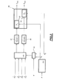
- FIG. 1 a diesel engine 10 is schematically illustrated. of a motor vehicle.
- This engine comprises a plurality of cylinders, for example 4 cylinders, which are fueled respectively by four injectors 12a, 12b, 12c, 12d, connected to means 14 forming a common rail fuel supply thereof.
- the engine 10 also comprises means 16 for admitting gas, in particular for supplying air to the cylinders of the engine 10 for the fuel combustion.
- the flue gases from combustion in the cylinders are collected at an exhaust manifold 20 and a part of the exhaust gas is taken from this manifold 20 by means 22 of exhaust gas recirculation (EGR), and injected at level of the means 16 for admitting gases.
- EGR exhaust gas recirculation
- the means of admission of the gases comprise for this purpose means mixture 24, for example a pilot valve or a T-fitting, adapted for mixing the air coming from an air inlet 26 and the part of the gases exhaust taken at the collector 20 and recycled at the inlet of the motor 10.
- the motor 10 further comprises means 28 for measuring the pressure in at least one cylinder of the engine.
- the means 28 for measuring the pressure in at least one cylinder are means of acquisition of pressure in each cylinder of the engine, and are for example consisting of a pressure sensor arranged in the glow plug of each cylinder.
- the engine 10 also comprises means 30 for acquiring the angle of the motor shaft, for example a toothed wheel fixed on the motor shaft and associated with a Hall effect sensor, as is known per se in the state of the technical.
- the means 30 are adapted to determine according to the angle of the motor shaft, the crankshaft angle of the engine cylinders in a manner known in the state of the art.
- the control of the operation of the engine is conventionally implemented by an operation control unit 32, or ECU unit, which receives among other things the pressure signals in the cylinders from the means 28 measurement and the crankshaft angle signal from the means 30 of acquisition, and realizes, according to these signals, a regulation of parameters injection of fuel into the cylinders or quantities of gas recycled exhaust for example.
- an operation control unit 32 or ECU unit, which receives among other things the pressure signals in the cylinders from the means 28 measurement and the crankshaft angle signal from the means 30 of acquisition, and realizes, according to these signals, a regulation of parameters injection of fuel into the cylinders or quantities of gas recycled exhaust for example.
- the unit 32 ECU comprises a subunit 34 implementing the system according to the invention, as described in more detail below.
- FIG. 2 is a schematic view of the determination system of FIG. minus a pressure value of the exhaust gas in the collector exhaust 20 implemented by the subunit 34 of 32 ECU unit.
- This system comprises acquisition means 40 receiving input the signals P 1 / cyl, P 2 / cyl, P 3 / cyl, P / cyl pressure in the cylinders from means 28 for measuring the pressure in the cylinders.
- acquisition means 40 acquisition are adapted to acquire the pressure value in each engine cylinder for at least one predetermined crank angle of acquisition of the cylinder.
- the acquisition means 40 are adapted to acquire the pressure in each cylinder of the engine for a first predetermined acquisition crank angle ⁇ 1 for which the pressure in the cylinder is representative of the average pressure of the gases in the collector exhaust system 20 and for a second angle ⁇ 2 predetermined acquisition crankshaft for which the pressure in the cylinder is representative of the maximum pressure of the gases in the exhaust manifold 20.
- Figure 3 illustrates the affine dependence that exists between the average pressure in the exhaust manifold and the pressure in the cylinder.
- the first curve A of this figure online continuous, corresponds to the average pressure measured in the collector exhaust of this engine in response to an acceleration instruction predetermined over several successive cycles of the engine.
- the second curve B of this figure corresponds at the estimated average pressure in the same manifold.
- This pressure estimated average was calculated by applying a predetermined affine relation to the measurements of the pressure in a cylinder of a Diesel engine object of this study for a crank angle equal to 180 ° vil after the PMH. As he is possible to see it, the error between the measured average pressure and the estimated average pressure is low, even for variations the average pressure measured.
- the pressure in a cylinder is representative of the maximum pressure in the exhaust manifold, as shown in Figure 4.
- Figure 4 illustrates indeed the affine dependence between the pressure maximum in the exhaust manifold and the pressure in the cylinder.
- the first curve A of this figure in a continuous line, corresponds to the maximum pressure measured in the exhaust manifold in response to a predetermined acceleration setpoint for successive cycles of the engine.
- the second curve B of this figure corresponds at the maximum estimated pressure in the exhaust manifold, obtained by the application of a second predetermined affine relation to the measurements of the pressure in a cylinder of the engine for a crank angle equal to 155 ° vil after the PMH.
- the estimation system further comprises means 42 for triggering the acquisition of the pressure value in each cylinder for the at least one acquisition crank angle, that is, ie crankshaft angles ⁇ 1 and ⁇ 2 .
- the triggering means 42 receive at input the crankshaft angle ⁇ of the cylinder of the crankshaft angle acquisition means and the predetermined acquisition crank angle ⁇ 1 and ⁇ 2 .
- the triggering means 42 activate the acquisition means 40 which acquire in response the pressure value in the cylinder for this crankshaft angle.
- the trigger means 42 trigger the acquisition of the pressure in the cylinder when the acquired crankshaft angle ⁇ is substantially equal to the acquisition angle ⁇ 2 .
- the values of the pressure in the cylinders for the crankshaft acquisition angles ⁇ 1 and ⁇ 2 are delivered to two buffers 44, 46 respectively for storing these values for later use.
- the estimation system also includes means 48 estimating average and maximum gas pressure in the collector exhaust as a function of the pressure value acquired in the at least one cylinder for the at least one crankshaft angle.
- the estimating means 48 comprise means 50 calculation of the average gas pressure in the exhaust manifold.
- the calculation means 50 receive as input these pressure values of the first buffer memory 44, and estimate the average pressure of the gas in the exhaust manifold according to the relation: or P coll is the average pressure in the collector, A ( ⁇ 1 ) and B ( ⁇ 1 ) are predetermined parameters depending on the crank angle of acquisition ⁇ 1 , M is the number of cylinders for which the acquisition of value pressure is achieved, that is to say the number of cylinders of the engine in the preferred embodiment of the system according to the invention, and P i / cyl ( ⁇ 1 ) is the pressure value acquired in the i th cylinder for which pressure acquisition is performed.
- the estimation means 48 also include means 52 for calculating the maximum pressure of the gases in the exhaust manifold.
- the calculation means 52 receive as input these values of the pressure of the second buffer memory 46, and estimate the maximum pressure of the gas in the exhaust manifold according to the relation: where P and coll is the maximum pressure in the collector, C ( ⁇ 2 ) and D ( ⁇ 2 ) are predetermined parameters as a function of the predetermined acquisition crankshaft angle ⁇ 2 , M is the number of cylinders for which Cylinder pressure value acquisition is performed, i.e. the number of engine cylinders in the preferred embodiment of the system according to the invention, and P i / cyl ( ⁇ 2 ) is the pressure value cylinder in the i th cylinder for which pressure acquisition is performed.
- the first angle ⁇ 1 is selected from a first predetermined set of at least one crankshaft angle for which the pressure in a cylinder is representative of the average pressure in the exhaust manifold, for example between 50 ° to 180 °, and preferably between 140 ° and 180 °.
- the acquisition angle ⁇ 2 is selected in a second predetermined set of at least one crank angle for which the pressure in a cylinder is representative of the maximum pressure in the exhaust manifold, for example between 50 And vil and 180 °, and preferably between 140 ° and 180 °.
- crankshaft angle ⁇ 1 and the coefficients A and B of the relation (1) used for the estimation of the average pressure in the exhaust manifold can be performed rapidly and automatically.
- This determination consists, for example, first of all in measuring the average pressure in the exhaust manifold of an engine Diesel test on N motor cycles, where N is a predetermined number.
- this determination consists in sampling the crankshaft angle interval [50 ° vil, 180 ° vil] after the TDC, and for each crank angle of this sampled interval, determining the values of the coefficients A and B of the relation (1) which minimizes the error e, for example quadratic average, between the measurement of the average pressure on the N motor cycles and the corresponding estimated average pressure for these N motor cycles determined using the relation (1) using the coefficients A and B, that is to say determine the values A and B solutions of the following problem of minimization: or P I (j) is the measure of the mean pressure in the exhaust manifold for the j th engine cycle, ⁇ is the crank angle interval sampled, and P i / cyl ( ⁇ , j) is the pressure in the i th cylinder for the crank angle ⁇ and for the j th engine cycle.
- P I (j) is the measure of the mean pressure in the exhaust manifold for the j th engine cycle
- ⁇ is the crank angle interval sampled
- crankshaft angle ⁇ 1 and the coefficients A and B of the relation (1) finally retained are those corresponding to the minimum of the minimum errors calculated for the crank angle of the sampled interval, that is to say providing the best accuracy for estimation.
- the number N of the engine cycle used for the determination of the values of the crank angle ⁇ 1 and the coefficients A and B of the relation (1) can be equal to 1, because it has been observed that the precision of the estimation of the average pressure obtained with such values is satisfactory.
- crankshaft angles ⁇ 1 and ⁇ 2 and the coefficients A, B, C and D are determined for the interval [140 °, 180 ° vil] after the TDC.
- This interval corresponds to the beginning of the exhaust phase of the cycle of a cylinder and allows a quick account of the variations of the pressure in the exhaust manifold.
- the selection of the angles ⁇ 1 and ⁇ 2 of acquisition can also be performed according to the desired accuracy on the value of the pressure in the exhaust manifold.
- the estimation system further comprises selection means 54 adapted to select the value of the angle ⁇ 1 and the value of the angle ⁇ 2 according to the desired accuracy for the average pressure and the maximum pressure in the exhaust manifold, stored for example as a default parameter in the ECU.
- the calculation means 50 and 52 additionally receive as input the values of the crank angle ⁇ 1 and ⁇ 2 respectively and are adapted to select the value of the parameters A, B, C and D according to these.
- the maximum pressure P and coll and / or the average pressure P coll in the exhaust manifold can be estimated on a part of the engine cycle or on a complete engine cycle.
- system according to the invention can also be cable circuit specially designed for that purpose or a information processing different from the ECU.
Landscapes
- Engineering & Computer Science (AREA)
- Chemical & Material Sciences (AREA)
- Combustion & Propulsion (AREA)
- Mechanical Engineering (AREA)
- General Engineering & Computer Science (AREA)
- Combined Controls Of Internal Combustion Engines (AREA)
- Measuring Fluid Pressure (AREA)
- Sampling And Sample Adjustment (AREA)
Abstract
Description
La présente invention concerne un système d'estimation d'au moins une valeur de la pression des gaz dans un collecteur d'échappement d'un moteur Diesel de véhicule automobile et un procédé de calibrage de ce système.The present invention relates to an estimation system of at least a value of the gas pressure in an exhaust manifold of an engine Motor vehicle diesel and a method of calibrating this system.
Plus particulièrement, la présente invention concerne un système d'estimation du type sous-mentionné appliqué à un moteur Diesel comprenant des moyens formant rampe commune d'alimentation en carburant des cylindres de celui-ci, des moyens de mesure de la pression dans au moins un cylindre et des moyens d'acquisition de l'angle vilebrequin du au moins un cylindre.More particularly, the present invention relates to a system of the type mentioned below applied to a Diesel engine comprising means forming a common rail for supplying the cylinders with fuel thereof, means for measuring the pressure in at least one cylinder and means for acquiring the crankshaft angle of the at least one cylinder.
La pression des gaz dans un collecteur d'échappement d'un moteur Diesel est un paramètre influençant le fonctionnement de celui-ci. Par exemple, dans le cas d'un moteur Diesel équipé d'un système de recirculation des gaz d'échappement, la recirculation des gaz d'échappement est en partie réalisée grâce à la différence de pression entre l'entrée d'admission du mélange air/gaz d'échappement dans le moteur et le collecteur des gaz d'échappement du moteur. Afin de réaliser un contrôle satisfaisant du débit et de la composition des gaz entrant dans le moteur, il est donc avantageux de connaítre la pression des gaz dans le collecteur.The pressure of the gases in an exhaust manifold of an engine Diesel is a parameter influencing the operation of it. For example, in the case of a diesel engine equipped with a gas recirculation system exhaust gas recirculation is partly achieved thanks to the pressure difference between the inlet intake of the air / gas mixture exhaust in the engine and the exhaust manifold of the engine. In order to achieve satisfactory control of the flow and composition of gas entering the engine, it is therefore advantageous to know the pressure of the gas in the collector.
De même, pour les moteurs Diesel équipés d'un turbocompresseur, la puissance de ce dernier dépend directement de la pression maximale des gaz dans le collecteur d'échappement. Là encore il peut être avantageux d'exploiter la valeur de la pression maximale dans le collecteur d'échappement pour réaliser un contrôle satisfaisant du turbocompresseur.Similarly, for diesel engines equipped with a turbocharger, the power of the latter depends directly on the maximum pressure of the gases in the exhaust manifold. Again it may be advantageous to exploit the value of the maximum pressure in the exhaust manifold to achieve satisfactory control of the turbocharger.
On connaít dans l'état de la technique des moteurs Diesel équipés d'un capteur de pression agencé dans le collecteur d'échappement de celui-ci afin de mesurer la pression des gaz. Toutefois, l'utilisation d'un capteur spécifique pose certains problèmes, comme la nécessité d'une connectique électrique supplémentaire, d'un calibrage régulier de celui-ci ou d'une maintenance supplémentaire. Par ailleurs, d'une manière générale, ce type de capteur est onéreux. It is known in the state of the art of diesel engines equipped with a pressure sensor arranged in the exhaust manifold thereof in order to measure the pressure of the gases. However, the use of a specific sensor poses some problems, such as the need for electrical connections additional, regular calibration or maintenance additional. Moreover, in general, this type of sensor is expensive.
Le but de la présente invention est de résoudre les problèmes susmentionnés en proposant un système d'estimation d'au moins une valeur de pression des gaz dans le collecteur d'échappement, notamment la pression maximale et la pression moyenne dans celui-ci, et n'utilisant donc pas de capteur de pression spécifique pour mesurer la pression des gaz dans le collecteur d'échappement du moteur.The object of the present invention is to solve the problems mentioned above by proposing a system for estimating at least one gas pressure in the exhaust manifold including pressure maximum and the average pressure in it, and therefore not using a sensor of specific pressure to measure the pressure of the gases in the collector engine exhaust.
A cet effet, la présente invention a pour objet un système d'estimation d'au moins une valeur de la pression des gaz dans un collecteur d'échappement d'un moteur Diesel de véhicule automobile, ce moteur comprenant des moyens formant rampe commune d'alimentation en carburant des cylindres de celui-ci, des moyens de mesure de la pression dans au moins un cylindre et des moyens d'acquisition de l'angle vilebrequin du au moins un cylindre, caractérisé en ce qu'il comprend :
- des moyens d'acquisition de la valeur de pression dans le au moins un cylindre du moteur pour au moins un angle vilebrequin d'acquisition prédéterminé ; et
- des moyens d'estimation de ladite au moins une valeur de pression dans le collecteur d'échappement en fonction de la valeur de pression acquise dans le au moins un cylindre pour le au moins un angle vilebrequin d'acquisition prédéterminé.
- means for acquiring the pressure value in the at least one cylinder of the engine for at least one predetermined acquisition crankshaft angle; and
- means for estimating said at least one pressure value in the exhaust manifold as a function of the pressure value acquired in the at least one cylinder for the at least one predetermined acquisition crankshaft angle.
Selon d'autres caractéristiques, le système est caractérisé en ce que :
- le au moins un angle vilebrequin prédéterminé d'acquisition est
compris dans un premier ensemble prédéterminé d'au moins un angle vilebrequin
pour lequel la pression cylindre dans le au moins un cylindre est représentative
de la pression moyenne dans le collecteur d'échappement, et en ce que :
- les moyens d'acquisition sont adaptés pour acquérir la valeur de pression dans le au moins un cylindre pour un angle vilebrequin d'acquisition prédéterminé de ce premier ensemble ; et
- les moyens d'estimation sont adaptés pour estimer la pression moyenne dans le collecteur d'échappement en fonction de la valeur de pression dans le au moins un cylindre pour cet angle vilebrequin d'acquisition prédéterminé.
- le premier ensemble d'au moins un angle vilebrequin possède des valeurs comprises entre 50° vil et 180° vil, et de préférence entre 140° vil et 180° vil.
- les moyens d'estimation sont adaptés pour estimer la pression moyenne dans le collecteur selon une relation prédéterminée en fonction de l'angle vilebrequin d'acquisition prédéterminé du premier ensemble ;
- les moyens d'estimation sont adaptés pour estimer la pression
moyenne dans le collecteur selon la relation :

P coll est la pression moyenne dans le collecteur, 1 est l'angle vilebrequin d'acquisition prédéterminé du premier ensemble, A(1) et B(1) sont des paramètres prédéterminés en fonction de l'angle vilebrequin d'acquisition 1 prédéterminé du premier ensemble, M est le nombre de cylindres pour lequel l'acquisition de valeur de pression est réalisée, et P i / cyl(1) est la valeur de pression acquise dans le ième cylindre pour lequel l'acquisition de pression est réalisée ; - le au moins un angle vilebrequin est compris dans un second
ensemble prédéterminé d'au moins un angle vilebrequin pour lequel la pression
cylindre dans le au moins un cylindre est représentative de la pression maximale
dans le collecteur d'échappement, et en ce que :
- les moyens d'acquisition sont adaptés pour acquérir la valeur de pression dans le au moins un cylindre pour un angle vilebrequin d'acquisition prédéterminé de ce second ensemble ; et
- les moyens d'estimation sont adaptés pour déterminer la pression maximale dans le collecteur d'échappement en fonction de la valeur de pression cylindre dans le au moins un cylindre pour cet angle vilebrequin d'acquisition prédéterminé.
- le second ensemble d'au moins un angle vilebrequin possède des valeurs comprises entre 50° vil et 180° vil, et de préférence entre 140° vil et 180° vil ;
- les moyens d'estimation sont adaptés pour estimer la pression maximale dans le collecteur selon une relation prédéterminée en fonction de l'angle vilebrequin d'acquisition prédéterminé du second ensemble ;
- les moyens d'estimation sont adaptés pour estimer la pression
maximale dans le collecteur selon la relation :
où P andcoll est la pression maximale dans le collecteur, 2 est l'angle vilebrequin d'acquisition prédéterminé du second ensemble, C(2) et D(2)sont des paramètres prédéterminés en fonction de l'angle vilebrequin d'acquisition prédéterminé2 du second ensemble, M est le nombre de cylindres pour lequel l'acquisition de valeur de pression cylindre est réalisée, et Pi cyl(2) est la valeur de pression cylindre dans le ième cylindre pour lequel l'acquisition de pression est réalisée.

- il comprend en outre des moyens de sélection adaptés pour sélectionner le au moins un angle vilebrequin d'acquisition en fonction de la précision souhaitée sur la au moins une valeur estimée de pression dans le collecteur d'échappement.
- the at least one predetermined crank angle of acquisition is comprised in a first predetermined set of at least one crankshaft angle for which the cylinder pressure in the at least one cylinder is representative of the average pressure in the exhaust manifold, and what:
- the acquisition means are adapted to acquire the pressure value in the at least one cylinder for a predetermined acquisition crank angle of the first set; and
- the estimation means are adapted to estimate the average pressure in the exhaust manifold as a function of the pressure value in the at least one cylinder for this predetermined acquisition crank angle.
- the first set of at least one crankshaft angle has values between 50 ° and 180 °, and preferably between 140 ° and 180 °.
- the estimation means are adapted to estimate the average pressure in the manifold in a predetermined relationship as a function of the predetermined acquisition crankshaft angle of the first set;
- the estimation means are adapted to estimate the average pressure in the manifold according to the relation:
P coll is the average pressure in the manifold, 1 is the predetermined acquisition crankshaft angle of the first set, A ( 1 ) and B ( 1 ) are predetermined parameters as a function of crank angle of acquisition 1 is the number of cylinders for which the pressure value acquisition is performed, and P i / cyl ( 1 ) is the pressure value acquired in the i th cylinder for which the acquisition of pressure is achieved; - the at least one crankshaft angle is within a second predetermined set of at least one crankshaft angle for which the cylinder pressure in the at least one cylinder is representative of the maximum pressure in the exhaust manifold, and that:
- the acquisition means are adapted to acquire the pressure value in the at least one cylinder for a predetermined acquisition crank angle of this second set; and
- the estimation means are adapted to determine the maximum pressure in the exhaust manifold as a function of the cylinder pressure value in the at least one cylinder for this predetermined acquisition crank angle.
- the second set of at least one crankshaft angle has values between 50 ° and 180 °, and preferably between 140 ° and 180 °;
- the estimation means are adapted to estimate the maximum pressure in the manifold in a predetermined relationship as a function of the predetermined acquisition crank angle of the second set;
- the estimation means are adapted to estimate the maximum pressure in the manifold according to the relation: where P and coll is the maximum pressure in the manifold, 2 is the predetermined acquisition crankshaft angle of the second set, C ( 2 ) and D ( 2 ) are predetermined parameters depending on the crankshaft angle d predetermined acquisition 2 of the second set, M is the number of cylinders for which the cylinder pressure value acquisition is performed, and P i cyl ( 2 ) is the cylinder pressure value in the i th cylinder for which pressure acquisition is performed.
- it further comprises selection means adapted to select the at least one crank angle of acquisition according to the desired accuracy on the at least one estimated value of pressure in the exhaust manifold.
L'invention a également pour objet un procédé de calibrage d'un système d'estimation du type susmentionné, les moyens d'estimation étant adaptés pour estimer la au moins une valeur de la pression dans le collecteur d'échappement selon une relation d'un type prédéterminé dépendant de paramètres, comprenant les étapes consistant à :
- réaliser une mesure, sur au moins un cycle moteur, de la au moins une valeur de la pression dans le collecteur d'échappement d'un moteur Diesel de véhicule automobile ;
- échantillonner un intervalle prédéterminé d'angles vilebrequin ;
- déterminer, pour chaque angle vilebrequin de l'intervalle d'angles vilebrequin échantillonné, les valeurs des paramètres de la fonction des moyens d'estimation qui correspondent à l'erreur minimale entre la mesure de la au moins une valeur de la pression dans le collecteur d'échappement et l'estimation correspondante déterminée au moyen de cette fonction ; et
- déterminer le au moins un angle vilebrequin du au moins un cylindre et les paramètres de la fonction des moyens d'estimation comme étant respectivement l'angle vilebrequin de l'intervalle d'angles vilebrequin échantillonné et les valeurs des paramètres de la fonction correspondants au minimum des erreurs minimales déterminées.
- performing a measurement, on at least one engine cycle, of the at least one value of the pressure in the exhaust manifold of a motor vehicle diesel engine;
- sampling a predetermined interval of crank angle;
- determining, for each crankshaft angle of the crank angle interval sampled, the values of the parameters of the function of the estimating means which correspond to the minimum error between the measurement of the at least one pressure value in the collector exhaust and the corresponding estimate determined by this function; and
- determining the at least one crankshaft angle of the at least one cylinder and the parameters of the function of the estimating means being respectively the crankshaft angle of the crankshaft angle interval sampled and the values of the corresponding function parameters to a minimum certain minimum errors.
La présente invention sera mieux comprise à la lecture de la description qui va suivre, donnée uniquement à titre d'exemple, et faite en relation avec les dessins annexés dans lesquels :
- la figure 1 est une vue schématique d'un moteur Diesel de véhicule automobile équipé d'une unité de contrôle du fonctionnement de celui-ci comprenant le système d'estimation selon l'invention ;
- la figure 2 est une vue schématique du système d'estimation selon l'invention entrant dans la constitution de l'unité de contrôle du fonctionnement du moteur de la figure 1,
- la figure 3 est un ensemble de courbes illustrant la dépendance entre la pression moyenne dans le collecteur d'échappement et la pression dans un cylindre; et
- la figure 4 est un ensemble de courbes illustrant la dépendance entre la pression maximale dans le collecteur d'échappement et la pression dans un cylindre.
- Figure 1 is a schematic view of a motor vehicle diesel engine equipped with a control unit of the operation thereof comprising the estimation system according to the invention;
- FIG. 2 is a schematic view of the estimation system according to the invention forming part of the control unit of the operation of the engine of FIG. 1,
- Figure 3 is a set of curves illustrating the dependence between the average pressure in the exhaust manifold and the pressure in a cylinder; and
- Figure 4 is a set of curves illustrating the dependence between the maximum pressure in the exhaust manifold and the pressure in a cylinder.
Sur la figure 1, on a illustré de façon schématique un moteur Diesel 10
de véhicule automobile. In FIG. 1, a
Ce moteur comprend une pluralité de cylindres, par exemple 4
cylindres, qui sont alimentés respectivement en carburant par quatre injecteurs
12a, 12b, 12c, 12d, raccordés à des moyens 14 formant rampe commune
d'alimentation en carburant de ceux-ci.This engine comprises a plurality of cylinders, for example 4
cylinders, which are fueled respectively by four
Le moteur 10 comprend également des moyens 16 d'admission de
gaz, notamment pour alimenter en air les cylindres du moteur 10 pour la
combustion du carburant. Les gaz brûlés issus de la combustion dans les
cylindres sont collectés au niveau d'un collecteur de gaz d'échappement 20 et
une partie des gaz d'échappement est prélevée au niveau de ce collecteur 20
par des moyens 22 de recirculation des gaz d'échappement (EGR), et injectés au
niveau des moyens 16 d'admission des gaz.The
Les moyens d'admission des gaz comprennent à cet effet des moyens
de mélange 24, par exemple une vanne pilotée ou un raccord en T, adaptés pour
mélanger l'air en provenance d'une entrée d'air 26 et la partie des gaz
d'échappement prélevée au niveau du collecteur 20 et recyclé en entrée du
moteur 10.The means of admission of the gases comprise for this purpose means
Le moteur 10 comprend par ailleurs des moyens 28 de mesure de la
pression dans au moins un cylindre du moteur. De manière préférentielle les
moyens 28 de mesure de la pression dans au moins un cylindre sont des moyens
d'acquisition de la pression dans chaque cylindre du moteur, et sont par exemple
constitués d'un capteur de pression agencé dans la bougie de préchauffage de
chaque cylindre.The
Le moteur 10 comprend également des moyens 30 d'acquisition de
l'angle de l'arbre moteur, par exemple une roue dentée fixée sur l'arbre moteur et
associée à un capteur à effet Hall, comme cela est connu en soi dans l'état de la
technique. Les moyens 30 sont adaptés pour déterminer en fonction de l'angle
de l'arbre moteur, l'angle vilebrequin des cylindres du moteur d'une manière
connue dans l'état de la technique.The
Le contrôle du fonctionnement du moteur est de manière classique mis
en oeuvre par une unité 32 de contrôle de fonctionnement, ou unité ECU, qui
reçoit entre autres les signaux de pression dans les cylindres à partir des moyens
28 de mesure et le signal d'angle vilebrequin à partir des moyens 30
d'acquisition, et réalise en fonction de ces signaux une régulation de paramètres
d'injection du carburant dans les cylindres ou des quantités de gaz
d'échappement recyclé par exemple.The control of the operation of the engine is conventionally
implemented by an
Dans un mode de réalisation du système selon l'invention, l'unité 32
ECU comprend une sous-unité 34 mettant en oeuvre le système selon l'invention,
comme cela est décrit plus en détail ci-dessous.In one embodiment of the system according to the invention, the
La figure 2 est une vue schématique du système de détermination d'au
moins une valeur de pression des gaz d'échappement dans le collecteur
d'échappement 20 mis en oeuvre par la sous-unité 34 de l'unité 32 ECU.FIG. 2 is a schematic view of the determination system of FIG.
minus a pressure value of the exhaust gas in the
Ce système comprend des moyens 40 d'acquisition recevant en entrée
les signaux P 1 / cyl, P 2 / cyl, P 3 / cyl, P / cyl de pression dans les cylindres en provenance
des moyens 28 de mesure de la pression dans les cylindres. Ces moyens 40
d'acquisition sont adaptés pour acquérir la valeur de pression dans chaque
cylindre du moteur pour au moins un angle vilebrequin prédéterminé d'acquisition
du cylindre.This system comprises acquisition means 40 receiving input
the
De manière préférentielle, les moyens 40 d'acquisition sont adaptés
pour acquérir la pression dans chaque cylindre du moteur pour un premier angle
vilebrequin 1 d'acquisition prédéterminé pour lequel la pression dans le cylindre
est représentative de la pression moyenne des gaz dans le collecteur
d'échappement 20 et pour un second angle 2 vilebrequin d'acquisition
prédéterminé pour lequel la pression dans le cylindre est représentative de la
pression maximale des gaz dans le collecteur d'échappement 20.Preferably, the acquisition means 40 are adapted to acquire the pressure in each cylinder of the engine for a first predetermined acquisition crank angle 1 for which the pressure in the cylinder is representative of the average pressure of the gases in the
Il peut en effet être démontré qu'il existe une correspondance entre la pression dans un cylindre et la pression dans le collecteur d'échappement.It can indeed be shown that there is a correspondence between the pressure in a cylinder and the pressure in the exhaust manifold.
Pour des angles vilebrequin prédéterminés après le point mort haut combustion (PMH) du cycle d'un cylindre, il peut être montré que la pression dans ce cylindre est représentative de la pression moyenne dans le collecteur d'échappement, comme cela est illustré par la figure 3. For predetermined crank angles after top dead center combustion (PMH) cycle of a cylinder, it can be shown that the pressure in this cylinder is representative of the average pressure in the manifold exhaust, as shown in Figure 3.
La figure 3 illustre en effet la dépendance affine qui existe entre la pression moyenne dans le collecteur d'échappement et la pression dans le cylindre.Figure 3 illustrates the affine dependence that exists between the average pressure in the exhaust manifold and the pressure in the cylinder.
Cette figure présente des résultats d'une étude antérieure réalisée sur un moteur Diesel associé à des moyens formant rampe d'alimentation commune en carburant des cylindres. La première courbe A de cette figure, en ligne continue, correspond à la pression moyenne mesurée dans le collecteur d'échappement de ce moteur en réponse à une consigne d'accélération prédéterminée sur plusieurs cycles successifs du moteur.This figure presents results from a previous study conducted on a diesel engine associated with means forming common feed ramp in fuel of the cylinders. The first curve A of this figure, online continuous, corresponds to the average pressure measured in the collector exhaust of this engine in response to an acceleration instruction predetermined over several successive cycles of the engine.
La seconde courbe B de cette figure, en ligne discontinue, correspond à la pression moyenne estimée dans le même collecteur. Cette pression moyenne estimée a été calculée en appliquant une relation affine prédéterminée aux mesures de la pression dans un cylindre d'un moteur Diesel objet de cette étude pour un angle vilebrequin égal à 180° vil après le PMH. Comme il est possible de le constater, l'erreur entre la pression moyenne mesurée et la pression moyenne estimée est faible, et cela même pour des variations importantes de la pression moyenne mesurée.The second curve B of this figure, in a broken line, corresponds at the estimated average pressure in the same manifold. This pressure estimated average was calculated by applying a predetermined affine relation to the measurements of the pressure in a cylinder of a Diesel engine object of this study for a crank angle equal to 180 ° vil after the PMH. As he is possible to see it, the error between the measured average pressure and the estimated average pressure is low, even for variations the average pressure measured.
Ainsi, il est possible d'estimer instantanément de façon fiable la pression moyenne dans le collecteur à l'aide d'une unique relation affine pour un angle vilebrequin prédéterminé.Thus, it is possible to estimate instantly reliably average pressure in the manifold using a single affine relationship for a predetermined crankshaft angle.
Pour des angles vilebrequin d'acquisition prédéterminés après le point mort haut combustion du cycle d'un cylindre, il peut être également montré que la pression dans un cylindre est représentative de la pression maximale dans le collecteur d'échappement, comme cela est illustré par la figure 4.For predetermined acquisition crank angles after the point death high combustion cycle of a cylinder, it can also be shown that the pressure in a cylinder is representative of the maximum pressure in the exhaust manifold, as shown in Figure 4.
La figure 4 illustre en effet la dépendance affine entre la pression maximale dans le collecteur d'échappement et la pression dans le cylindre.Figure 4 illustrates indeed the affine dependence between the pressure maximum in the exhaust manifold and the pressure in the cylinder.
Cette figure présente également les résultats de l'étude antérieure réalisée sur le moteur Diesel susmentionné.This figure also presents the results of the previous study performed on the aforementioned diesel engine.
La première courbe A de cette figure, en ligne continue, correspond à la pression maximale mesurée dans le collecteur d'échappement en réponse à une consigne d'accélération prédéterminée pour des cycles successifs du moteur.The first curve A of this figure, in a continuous line, corresponds to the maximum pressure measured in the exhaust manifold in response to a predetermined acceleration setpoint for successive cycles of the engine.
La seconde courbe B de cette figure, en ligne discontinue, correspond à la pression maximale estimée dans le collecteur d'échappement, obtenue par l'application d'une seconde relation affine prédéterminée aux mesures de la pression dans un cylindre du moteur pour un angle vilebrequin égal à 155° vil après le PMH.The second curve B of this figure, in a broken line, corresponds at the maximum estimated pressure in the exhaust manifold, obtained by the application of a second predetermined affine relation to the measurements of the pressure in a cylinder of the engine for a crank angle equal to 155 ° vil after the PMH.
Là encore, l'erreur entre la pression maximale mesurée et la pression maximale estimée est faible, et cela même pour des variations importantes de la pression maximale mesurée. Ceci illustre le fait qu'il est également possible d'estimer instantanément de façon fiable la pression maximale dans le collecteur d'échappement en fonction de la pression dans un cylindre du moteur en appliquant une relation affine prédéterminée pour un angle vilebrequin prédéterminé.Again, the error between the measured maximum pressure and the pressure the estimated maximum is small, even for large variations in measured maximum pressure. This illustrates the fact that it is also possible to instantly estimate the maximum pressure in the collector exhaust as a function of the pressure in a cylinder of the engine in applying a predetermined affine relation for a crankshaft angle predetermined.
La détermination des relations affines susmentionnées, ainsi que la détermination des angles vilebrequin, utilisés pour ces estimations seront expliquées plus en détail par la suite.The determination of the aforementioned affine relationships, as well as the Crank angle determination, used for these estimates will be explained in more detail later.
En se référant à nouveau à la figure 2, le système d'estimation comprend en outre des moyens 42 de déclenchement de l'acquisition de la valeur de pression dans chaque cylindre pour le au moins un angle vilebrequin d'acquisition, c'est-à-dire les angles vilebrequin 1 et 2.Referring again to FIG. 2, the estimation system further comprises means 42 for triggering the acquisition of the pressure value in each cylinder for the at least one acquisition crank angle, that is, ie crankshaft angles 1 and 2 .
A cet effet, les moyens 42 de déclenchement reçoivent en entrée l'angle vilebrequin du cylindre des moyens d'acquisition de l'angle vilebrequin et les angles vilebrequin prédéterminés d'acquisition 1 et 2.For this purpose, the triggering means 42 receive at input the crankshaft angle of the cylinder of the crankshaft angle acquisition means and the predetermined acquisition crank angle 1 and 2 .
Lorsque l'angle vilebrequin du cylindre est sensiblement égal à l'angle vilebrequin d'acquisition 1, les moyens 42 de déclenchement activent les moyens 40 d'acquisition qui acquièrent en réponse la valeur de pression dans le cylindre pour cet angle vilebrequin. When the crankshaft angle of the cylinder is substantially equal to the acquisition crankshaft angle 1 , the triggering means 42 activate the acquisition means 40 which acquire in response the pressure value in the cylinder for this crankshaft angle.
D'une manière analogue, les moyens 42 de déclenchement déclenchent l'acquisition de la pression dans le cylindre lorsque l'angle vilebrequin acquis est sensiblement égal à l'angle d'acquisition 2.Similarly, the trigger means 42 trigger the acquisition of the pressure in the cylinder when the acquired crankshaft angle is substantially equal to the acquisition angle 2 .
Les valeurs de la pression dans les cylindres pour les angles
vilebrequin d'acquisition 1 et 2 sont délivrés à deux mémoires tampons 44, 46
respectivement pour la mémorisation de ces valeurs à des fins d'utilisation
ultérieure.The values of the pressure in the cylinders for the crankshaft acquisition angles 1 and 2 are delivered to two
Le système d'estimation comprend également des moyens 48
d'estimation de la pression moyenne et maximale des gaz dans le collecteur
d'échappement en fonction de la valeur de pression acquise dans le au moins un
cylindre pour le au moins un angle vilebrequin.The estimation system also includes
A cet effet, les moyens 48 d'estimation comprennent des moyens 50 de calcul de la pression moyenne des gaz dans le collecteur d'échappement.For this purpose, the estimating means 48 comprise means 50 calculation of the average gas pressure in the exhaust manifold.
Une fois terminée l'acquisition des valeurs de la pression dans les
cylindres pour l'angle vilebrequin d'acquisition 1, les moyens 50 de calcul
reçoivent en entrée ces valeurs de pression de la première mémoire tampon 44,
et estiment la pression moyenne des gaz dans le collecteur d'échappement selon
la relation :

Les moyens 48 d'estimation comprennent également des moyens 52 de calcul de la pression maximale des gaz dans le collecteur d'échappement.The estimation means 48 also include means 52 for calculating the maximum pressure of the gases in the exhaust manifold.
Une fois terminée l'acquisition des valeurs de pression dans les
cylindres pour l'angle vilebrequin d'acquisition 2, les moyens 52 de calcul
reçoivent en entrée ces valeurs de la pression de la seconde mémoire tampon
46, et estiment la pression maximale des gaz dans le collecteur d'échappement
selon la relation :

Le premier angle 1 est sélectionné dans un premier ensemble prédéterminé d'au moins un angle vilebrequin pour lequel la pression dans un cylindre est représentative de la pression moyenne dans le collecteur d'échappement, par exemple entre 50° vil et 180° vil, et de préférence entre 140° vil et 180° vil. De manière analogue, l'angle 2 d'acquisition est sélectionné dans un second ensemble prédéterminé d'au moins un angle vilebrequin pour lequel la pression dans un cylindre est représentative de la pression maximale dans le collecteur d'échappement, par exemple entre 50° vil et 180° vil, et de préférence entre 140° vil et 180° vil.The first angle 1 is selected from a first predetermined set of at least one crankshaft angle for which the pressure in a cylinder is representative of the average pressure in the exhaust manifold, for example between 50 ° to 180 °, and preferably between 140 ° and 180 °. Similarly, the acquisition angle 2 is selected in a second predetermined set of at least one crank angle for which the pressure in a cylinder is representative of the maximum pressure in the exhaust manifold, for example between 50 And vil and 180 °, and preferably between 140 ° and 180 °.
La détermination de l'angle vilebrequin 1 et des coefficients A et B de la relation (1) utilisés pour l'estimation de la pression moyenne dans le collecteur d'échappement peut être réalisée de manière rapide et automatique. The determination of the crankshaft angle 1 and the coefficients A and B of the relation (1) used for the estimation of the average pressure in the exhaust manifold can be performed rapidly and automatically.
Cette détermination consiste par exemple tout d'abord à réaliser une mesure de la pression moyenne dans le collecteur d'échappement d'un moteur Diesel de test sur N cycles moteur, où N est un nombre prédéterminé.This determination consists, for example, first of all in measuring the average pressure in the exhaust manifold of an engine Diesel test on N motor cycles, where N is a predetermined number.
Puis, cette détermination consiste à réaliser un échantillonnage de
l'intervalle d'angles vilebrequin [50° vil, 180 °vil] après le PMH, et, pour chaque
angle vilebrequin de cet intervalle échantillonné, déterminer les valeurs des
coefficients A et B de la relation (1) qui minimisent l'erreur e, par exemple
quadratique moyenne, entre la mesure de la pression moyenne sur les N cycles
moteur et la pression moyenne estimée correspondante pour ces N cycles
moteur déterminée au moyen de la relation (1) utilisant les coefficients A et B,
c'est-à-dire déterminer les valeurs A et B solutions du problème de minimisation
suivant :

Les valeurs de l'angle vilebrequin 1 et des coefficients A et B de la relation (1) finalement retenues sont celles correspondant au minimum des erreurs minimales calculées pour les angles vilebrequin de l'intervalle échantillonné, c'est-à-dire celle fournissant la meilleure précision pour l'estimation.The values of the crankshaft angle 1 and the coefficients A and B of the relation (1) finally retained are those corresponding to the minimum of the minimum errors calculated for the crank angle of the sampled interval, that is to say providing the best accuracy for estimation.
Le nombre N de cycle moteur utilisé pour la détermination des valeurs de l'angle vilebrequin 1 et des coefficients A et B de la relation (1) peut être égal à 1, car il a été observé que la précision de l'estimation de la pression moyenne obtenue au moyen de telles valeurs est satisfaisante. The number N of the engine cycle used for the determination of the values of the crank angle 1 and the coefficients A and B of the relation (1) can be equal to 1, because it has been observed that the precision of the estimation of the average pressure obtained with such values is satisfactory.
D'une manière analogue, il est possible de déterminer l'angle vilebrequin 2 et les coefficients C et D de la relation (2) utilisés pour l'estimation de la pression maximale dans le collecteur d'échappement de manière fiable et automatique en mettant en oeuvre le procédé de détermination susmentionné.In a similar way, it is possible to determine the crankshaft angle 2 and the coefficients C and D of the relation (2) used for the estimation of the maximum pressure in the exhaust manifold in a reliable and automatic manner. implementing the aforementioned determination method.
De manière avantageuse, la détermination des angles vilebrequin 1 et 2 et des coefficients A, B, C et D est réalisée pour l'intervalle [140° vil, 180° vil] après le PMH. Cet intervalle correspond en effet au début de la phase d'échappement du cycle d'un cylindre et permet une prise en compte rapide des variations de la pression dans le collecteur d'échappement.Advantageously, the crankshaft angles 1 and 2 and the coefficients A, B, C and D are determined for the interval [140 °, 180 ° vil] after the TDC. This interval corresponds to the beginning of the exhaust phase of the cycle of a cylinder and allows a quick account of the variations of the pressure in the exhaust manifold.
Il est possible de déterminer plusieurs jeux de valeurs d'angles
vilebrequin et de coefficients pour chacune des relations affines (1) et (2). Le
choix final d'un ensemble de ces valeurs est alors réalisé en fonction, par
exemple, de contraintes de conceptions et/ou de contraintes technologiques
portant par exemple sur le choix des moyens 28 de mesure de la pression dans
les cylindres.It is possible to determine several sets of angle values
crankshaft and coefficients for each affine relationship (1) and (2). The
final choice of a set of these values is then made based on, by
example, design constraints and / or technological constraints
for example on the choice of
La sélection des angles 1 et 2 d'acquisition peut également être réalisée en fonction de la précision souhaitée sur la valeur de la pression dans le collecteur d'échappement.The selection of the angles 1 and 2 of acquisition can also be performed according to the desired accuracy on the value of the pressure in the exhaust manifold.
Pour la sélection des angles vilebrequin d'acquisition, le système d'estimation comprend en outre des moyens 54 de sélection adaptés pour sélectionner la valeur de l'angle 1 et la valeur de l'angle 2 en fonction de la précision souhaitée pour la pression moyenne et la pression maximale dans le collecteur d'échappement, mémorisée par exemple comme un paramètre par défaut dans l'unité ECU.For selection of crank angle acquisition, the estimation system further comprises selection means 54 adapted to select the value of the angle 1 and the value of the angle 2 according to the desired accuracy for the average pressure and the maximum pressure in the exhaust manifold, stored for example as a default parameter in the ECU.
Pour tenir compte de la dépendance de paramètres A, B, C et D aux valeurs des angles vilebrequin, les moyens de calcul 50 et 52 reçoivent en outre comme entrée les valeurs des angles vilebrequin 1 et 2 respectivement et sont adaptés pour sélectionner les valeur des paramètres A, B, C et D en fonction de ceux-ci. To take account of the dependence of parameters A, B, C and D on the values of the crank angle, the calculation means 50 and 52 additionally receive as input the values of the crank angle 1 and 2 respectively and are adapted to select the value of the parameters A, B, C and D according to these.
Ainsi, la pression maximale P andcoll et/ou la pression moyenne
Bien entendu d'autres modes de réalisation sont possibles. On comprendra par exemple qu'il est possible de n'estimer que la pression moyenne dans le collecteur d'échappement ou uniquement la pression maximale en fonction des besoins du contrôle du fonctionnement du moteur.Of course other embodiments are possible. We understand for example that it is possible to estimate only the average pressure in the exhaust manifold or only the maximum pressure in according to the needs of the control of the operation of the engine.
De même il est possible d'acquérir plusieurs fois la pression dans les
cylindres pour l'angle d'acquisition 1 et/ou 2, par exemple pour N cycles
moteur. En utilisant une telle pluralité d'acquisitions, il est alors possible
d'effectuer un moyennage des valeurs
De plus, le système selon l'invention peut également être mis en oeuvre dans un circuit câblé spécialement prévu à cet effet ou une unité de traitement d'informations différente de l'unité ECU.In addition, the system according to the invention can also be cable circuit specially designed for that purpose or a information processing different from the ECU.
Claims (11)


Applications Claiming Priority (2)
| Application Number | Priority Date | Filing Date | Title |
|---|---|---|---|
| FR0406361 | 2004-06-11 | ||
| FR0406361A FR2871521B1 (en) | 2004-06-11 | 2004-06-11 | SYSTEM FOR ESTIMATING PRESSURE IN THE EXHAUST MANIFOLD OF A DIESEL ENGINE AND METHOD OF CALIBRATING IT |
Publications (2)
| Publication Number | Publication Date |
|---|---|
| EP1607605A1 true EP1607605A1 (en) | 2005-12-21 |
| EP1607605B1 EP1607605B1 (en) | 2007-06-20 |
Family
ID=34947636
Family Applications (1)
| Application Number | Title | Priority Date | Filing Date |
|---|---|---|---|
| EP05300454A Not-in-force EP1607605B1 (en) | 2004-06-11 | 2005-06-03 | Pressure estimating system in the exhaust manifold of a diesel engine and method for calibrating said system |
Country Status (4)
| Country | Link |
|---|---|
| EP (1) | EP1607605B1 (en) |
| AT (1) | ATE365270T1 (en) |
| DE (1) | DE602005001422T2 (en) |
| FR (1) | FR2871521B1 (en) |
Cited By (3)
| Publication number | Priority date | Publication date | Assignee | Title |
|---|---|---|---|---|
| GB2473435A (en) * | 2009-09-09 | 2011-03-16 | Gm Global Tech Operations Inc | Estimating i.c. engine exhaust manifold pressure using combustion chamber pressure values |
| EP2754875A1 (en) * | 2013-01-15 | 2014-07-16 | Robert Bosch Gmbh | Method of operating a combustion engine |
| US20140196704A1 (en) * | 2011-04-22 | 2014-07-17 | Borgwarner Inc. | Turbocharger boost control using exhaust pressure estimated from engine cylinder pressure |
Families Citing this family (1)
| Publication number | Priority date | Publication date | Assignee | Title |
|---|---|---|---|---|
| FR2892453B1 (en) * | 2005-10-24 | 2010-12-17 | Renault Sas | METHOD AND DEVICE FOR ESTIMATING REGULATING PRESSURE IN THE INTAKE MANIFOLD OF AN INTERNAL COMBUSTION ENGINE |
Citations (2)
| Publication number | Priority date | Publication date | Assignee | Title |
|---|---|---|---|---|
| EP1162357A2 (en) * | 2000-06-10 | 2001-12-12 | Volkswagen Aktiengesellschaft | Method and apparatus for monitoring the operations of an engine |
| WO2004048761A1 (en) * | 2002-11-27 | 2004-06-10 | Ricardo Uk Limited | Improved engine management |
-
2004
- 2004-06-11 FR FR0406361A patent/FR2871521B1/en not_active Expired - Fee Related
-
2005
- 2005-06-03 AT AT05300454T patent/ATE365270T1/en not_active IP Right Cessation
- 2005-06-03 DE DE602005001422T patent/DE602005001422T2/en active Active
- 2005-06-03 EP EP05300454A patent/EP1607605B1/en not_active Not-in-force
Patent Citations (2)
| Publication number | Priority date | Publication date | Assignee | Title |
|---|---|---|---|---|
| EP1162357A2 (en) * | 2000-06-10 | 2001-12-12 | Volkswagen Aktiengesellschaft | Method and apparatus for monitoring the operations of an engine |
| WO2004048761A1 (en) * | 2002-11-27 | 2004-06-10 | Ricardo Uk Limited | Improved engine management |
Cited By (4)
| Publication number | Priority date | Publication date | Assignee | Title |
|---|---|---|---|---|
| GB2473435A (en) * | 2009-09-09 | 2011-03-16 | Gm Global Tech Operations Inc | Estimating i.c. engine exhaust manifold pressure using combustion chamber pressure values |
| US20140196704A1 (en) * | 2011-04-22 | 2014-07-17 | Borgwarner Inc. | Turbocharger boost control using exhaust pressure estimated from engine cylinder pressure |
| US9551286B2 (en) * | 2011-04-22 | 2017-01-24 | Borgwarner Inc. | Turbocharger boost control using exhaust pressure estimated from engine cylinder pressure |
| EP2754875A1 (en) * | 2013-01-15 | 2014-07-16 | Robert Bosch Gmbh | Method of operating a combustion engine |
Also Published As
| Publication number | Publication date |
|---|---|
| FR2871521B1 (en) | 2008-08-01 |
| FR2871521A1 (en) | 2005-12-16 |
| DE602005001422T2 (en) | 2008-02-14 |
| EP1607605B1 (en) | 2007-06-20 |
| DE602005001422D1 (en) | 2007-08-02 |
| ATE365270T1 (en) | 2007-07-15 |
Similar Documents
| Publication | Publication Date | Title |
|---|---|---|
| FR2739331A1 (en) | METHOD AND DEVICE FOR CONTROLLING THE DRIVE UNIT OF A MOTOR VEHICLE | |
| EP1548418B9 (en) | Calibration system of the pressure measuring chain in a automotive vehicle Diesel engine cylinder | |
| EP2935828B1 (en) | Supercharged engine diagnostics method and associated engine | |
| FR2893984A1 (en) | Cylinder`s operating condition determining method for e.g. petrol engine, involves evaluating time deviation of angle of rotation for each combustion cycle of cylinder of internal combustion engine | |
| FR2886345A1 (en) | METHOD OF ESTIMATING AN ADAPTIVE NON-LINEAR FILTER OF WEALTH IN A CYLINDER OF A COMBUSTION ENGINE | |
| FR2689934A1 (en) | Method and device for detecting combustion irregularities of an engine, in particular at medium and high revs, application to a control system of an injection engine. | |
| EP1607605B1 (en) | Pressure estimating system in the exhaust manifold of a diesel engine and method for calibrating said system | |
| EP0686762A1 (en) | Method and apparatus for determining specific parameters of injectors for combustion engines, in particular diesel engines with pre-injection | |
| FR2973441A1 (en) | Method for acquiring composition of intake gas in air distributor of internal combustion engine of car, involves calculating estimated value of parameter relative to composition of intake gas using state observer | |
| EP0599729B1 (en) | Method for controlling the exhaust gas recirculation in an internal combustion engine | |
| EP3201443B1 (en) | Motor vehicle combustion engine with improved mixture strength control | |
| EP1671023B1 (en) | Engine air supply control method which is intended, for example, for the control of a turbocharged engine | |
| FR2835281A1 (en) | Method for estimating mass of air admitted into engine combustion chamber consists of modeling air mass as function of pressure variation in combustion chamber from polytropic gas compression law | |
| FR3110200A1 (en) | Device and method for detecting a failure of an internal combustion engine for a motor vehicle | |
| EP2655838B1 (en) | System and method for controlling an internal combustion engine for a motor vehicle in transit | |
| EP2256322B1 (en) | Effect of the nox control on the combustion noise control in an internal combustion engine | |
| EP1787020B1 (en) | System for controlling the operation of a diesel engine of a motor vehicle | |
| FR2757945A1 (en) | METHOD FOR CALCULATING THE TORQUE OF AN ELECTRONICALLY CONTROLLED INJECTION THERMAL MOTOR | |
| EP0736680B1 (en) | Method of self-correction of physical parameters in a dynamic system such as an internal combustion engine | |
| EP0639704A1 (en) | Method for calculating the mass of air admitted to an internal combustion engine | |
| WO2008125189A1 (en) | Method and device for determining the “stroking” of an internal combustion v-engine | |
| FR2945078A1 (en) | METHOD FOR CONTROLLING THE OPERATION OF AN ENGINE | |
| WO2023072565A1 (en) | Method for estimating the atmospheric pressure of an internal combustion engine | |
| EP3995685A1 (en) | Method for diagnosing an air flowmeter for an internal combustion engine | |
| EP2264298A1 (en) | Method of estimating the pressure downstream of a throttle valve in a supercharged engine |
Legal Events
| Date | Code | Title | Description |
|---|---|---|---|
| PUAI | Public reference made under article 153(3) epc to a published international application that has entered the european phase |
Free format text: ORIGINAL CODE: 0009012 |
|
| AK | Designated contracting states |
Kind code of ref document: A1 Designated state(s): AT BE BG CH CY CZ DE DK EE ES FI FR GB GR HU IE IS IT LI LT LU MC NL PL PT RO SE SI SK TR |
|
| AX | Request for extension of the european patent |
Extension state: AL BA HR LV MK YU |
|
| 17P | Request for examination filed |
Effective date: 20060107 |
|
| AKX | Designation fees paid |
Designated state(s): AT BE BG CH CY CZ DE DK EE ES FI FR GB GR HU IE IS IT LI LT LU MC NL PL PT RO SE SI SK TR |
|
| GRAP | Despatch of communication of intention to grant a patent |
Free format text: ORIGINAL CODE: EPIDOSNIGR1 |
|
| RIN1 | Information on inventor provided before grant (corrected) |
Inventor name: SOUCHON, VINCENT |
|
| GRAS | Grant fee paid |
Free format text: ORIGINAL CODE: EPIDOSNIGR3 |
|
| GRAA | (expected) grant |
Free format text: ORIGINAL CODE: 0009210 |
|
| AK | Designated contracting states |
Kind code of ref document: B1 Designated state(s): AT BE BG CH CY CZ DE DK EE ES FI FR GB GR HU IE IS IT LI LT LU MC NL PL PT RO SE SI SK TR |
|
| REG | Reference to a national code |
Ref country code: GB Ref legal event code: FG4D Free format text: NOT ENGLISH |
|
| GBT | Gb: translation of ep patent filed (gb section 77(6)(a)/1977) |
Effective date: 20070620 |
|
| REG | Reference to a national code |
Ref country code: CH Ref legal event code: EP |
|
| REG | Reference to a national code |
Ref country code: IE Ref legal event code: FG4D Free format text: LANGUAGE OF EP DOCUMENT: FRENCH |
|
| REF | Corresponds to: |
Ref document number: 602005001422 Country of ref document: DE Date of ref document: 20070802 Kind code of ref document: P |
|
| PG25 | Lapsed in a contracting state [announced via postgrant information from national office to epo] |
Ref country code: SE Free format text: LAPSE BECAUSE OF FAILURE TO SUBMIT A TRANSLATION OF THE DESCRIPTION OR TO PAY THE FEE WITHIN THE PRESCRIBED TIME-LIMIT Effective date: 20070920 |
|
| PG25 | Lapsed in a contracting state [announced via postgrant information from national office to epo] |
Ref country code: PL Free format text: LAPSE BECAUSE OF FAILURE TO SUBMIT A TRANSLATION OF THE DESCRIPTION OR TO PAY THE FEE WITHIN THE PRESCRIBED TIME-LIMIT Effective date: 20070620 Ref country code: AT Free format text: LAPSE BECAUSE OF FAILURE TO SUBMIT A TRANSLATION OF THE DESCRIPTION OR TO PAY THE FEE WITHIN THE PRESCRIBED TIME-LIMIT Effective date: 20070620 |
|
| NLV1 | Nl: lapsed or annulled due to failure to fulfill the requirements of art. 29p and 29m of the patents act | ||
| REG | Reference to a national code |
Ref country code: IE Ref legal event code: FD4D |
|
| PG25 | Lapsed in a contracting state [announced via postgrant information from national office to epo] |
Ref country code: PT Free format text: LAPSE BECAUSE OF FAILURE TO SUBMIT A TRANSLATION OF THE DESCRIPTION OR TO PAY THE FEE WITHIN THE PRESCRIBED TIME-LIMIT Effective date: 20071120 Ref country code: BG Free format text: LAPSE BECAUSE OF FAILURE TO SUBMIT A TRANSLATION OF THE DESCRIPTION OR TO PAY THE FEE WITHIN THE PRESCRIBED TIME-LIMIT Effective date: 20070920 Ref country code: SI Free format text: LAPSE BECAUSE OF FAILURE TO SUBMIT A TRANSLATION OF THE DESCRIPTION OR TO PAY THE FEE WITHIN THE PRESCRIBED TIME-LIMIT Effective date: 20070620 Ref country code: CZ Free format text: LAPSE BECAUSE OF FAILURE TO SUBMIT A TRANSLATION OF THE DESCRIPTION OR TO PAY THE FEE WITHIN THE PRESCRIBED TIME-LIMIT Effective date: 20070620 Ref country code: IS Free format text: LAPSE BECAUSE OF FAILURE TO SUBMIT A TRANSLATION OF THE DESCRIPTION OR TO PAY THE FEE WITHIN THE PRESCRIBED TIME-LIMIT Effective date: 20071020 Ref country code: ES Free format text: LAPSE BECAUSE OF FAILURE TO SUBMIT A TRANSLATION OF THE DESCRIPTION OR TO PAY THE FEE WITHIN THE PRESCRIBED TIME-LIMIT Effective date: 20071001 Ref country code: NL Free format text: LAPSE BECAUSE OF FAILURE TO SUBMIT A TRANSLATION OF THE DESCRIPTION OR TO PAY THE FEE WITHIN THE PRESCRIBED TIME-LIMIT Effective date: 20070620 Ref country code: IE Free format text: LAPSE BECAUSE OF FAILURE TO SUBMIT A TRANSLATION OF THE DESCRIPTION OR TO PAY THE FEE WITHIN THE PRESCRIBED TIME-LIMIT Effective date: 20070620 |
|
| PG25 | Lapsed in a contracting state [announced via postgrant information from national office to epo] |
Ref country code: LT Free format text: LAPSE BECAUSE OF FAILURE TO SUBMIT A TRANSLATION OF THE DESCRIPTION OR TO PAY THE FEE WITHIN THE PRESCRIBED TIME-LIMIT Effective date: 20070620 Ref country code: SK Free format text: LAPSE BECAUSE OF FAILURE TO SUBMIT A TRANSLATION OF THE DESCRIPTION OR TO PAY THE FEE WITHIN THE PRESCRIBED TIME-LIMIT Effective date: 20070620 |
|
| REG | Reference to a national code |
Ref country code: GB Ref legal event code: 746 Effective date: 20080329 |
|
| PLBE | No opposition filed within time limit |
Free format text: ORIGINAL CODE: 0009261 |
|
| STAA | Information on the status of an ep patent application or granted ep patent |
Free format text: STATUS: NO OPPOSITION FILED WITHIN TIME LIMIT |
|
| PG25 | Lapsed in a contracting state [announced via postgrant information from national office to epo] |
Ref country code: DK Free format text: LAPSE BECAUSE OF FAILURE TO SUBMIT A TRANSLATION OF THE DESCRIPTION OR TO PAY THE FEE WITHIN THE PRESCRIBED TIME-LIMIT Effective date: 20070620 Ref country code: IT Free format text: LAPSE BECAUSE OF FAILURE TO SUBMIT A TRANSLATION OF THE DESCRIPTION OR TO PAY THE FEE WITHIN THE PRESCRIBED TIME-LIMIT Effective date: 20070620 Ref country code: GR Free format text: LAPSE BECAUSE OF FAILURE TO SUBMIT A TRANSLATION OF THE DESCRIPTION OR TO PAY THE FEE WITHIN THE PRESCRIBED TIME-LIMIT Effective date: 20070921 |
|
| 26N | No opposition filed |
Effective date: 20080325 |
|
| PG25 | Lapsed in a contracting state [announced via postgrant information from national office to epo] |
Ref country code: RO Free format text: LAPSE BECAUSE OF FAILURE TO SUBMIT A TRANSLATION OF THE DESCRIPTION OR TO PAY THE FEE WITHIN THE PRESCRIBED TIME-LIMIT Effective date: 20070620 |
|
| BERE | Be: lapsed |
Owner name: PEUGEOT CITROEN AUTOMOBILES SA Effective date: 20080630 |
|
| PG25 | Lapsed in a contracting state [announced via postgrant information from national office to epo] |
Ref country code: MC Free format text: LAPSE BECAUSE OF NON-PAYMENT OF DUE FEES Effective date: 20080630 |
|
| PG25 | Lapsed in a contracting state [announced via postgrant information from national office to epo] |
Ref country code: FI Free format text: LAPSE BECAUSE OF FAILURE TO SUBMIT A TRANSLATION OF THE DESCRIPTION OR TO PAY THE FEE WITHIN THE PRESCRIBED TIME-LIMIT Effective date: 20070620 |
|
| PG25 | Lapsed in a contracting state [announced via postgrant information from national office to epo] |
Ref country code: BE Free format text: LAPSE BECAUSE OF NON-PAYMENT OF DUE FEES Effective date: 20080630 |
|
| PG25 | Lapsed in a contracting state [announced via postgrant information from national office to epo] |
Ref country code: EE Free format text: LAPSE BECAUSE OF FAILURE TO SUBMIT A TRANSLATION OF THE DESCRIPTION OR TO PAY THE FEE WITHIN THE PRESCRIBED TIME-LIMIT Effective date: 20070620 |
|
| PG25 | Lapsed in a contracting state [announced via postgrant information from national office to epo] |
Ref country code: CY Free format text: LAPSE BECAUSE OF FAILURE TO SUBMIT A TRANSLATION OF THE DESCRIPTION OR TO PAY THE FEE WITHIN THE PRESCRIBED TIME-LIMIT Effective date: 20070620 |
|
| REG | Reference to a national code |
Ref country code: CH Ref legal event code: PL |
|
| PG25 | Lapsed in a contracting state [announced via postgrant information from national office to epo] |
Ref country code: CH Free format text: LAPSE BECAUSE OF NON-PAYMENT OF DUE FEES Effective date: 20090630 Ref country code: LI Free format text: LAPSE BECAUSE OF NON-PAYMENT OF DUE FEES Effective date: 20090630 |
|
| PG25 | Lapsed in a contracting state [announced via postgrant information from national office to epo] |
Ref country code: HU Free format text: LAPSE BECAUSE OF FAILURE TO SUBMIT A TRANSLATION OF THE DESCRIPTION OR TO PAY THE FEE WITHIN THE PRESCRIBED TIME-LIMIT Effective date: 20071221 Ref country code: LU Free format text: LAPSE BECAUSE OF NON-PAYMENT OF DUE FEES Effective date: 20080603 |
|
| PG25 | Lapsed in a contracting state [announced via postgrant information from national office to epo] |
Ref country code: TR Free format text: LAPSE BECAUSE OF FAILURE TO SUBMIT A TRANSLATION OF THE DESCRIPTION OR TO PAY THE FEE WITHIN THE PRESCRIBED TIME-LIMIT Effective date: 20070620 |
|
| PGFP | Annual fee paid to national office [announced via postgrant information from national office to epo] |
Ref country code: GB Payment date: 20140527 Year of fee payment: 10 |
|
| PGFP | Annual fee paid to national office [announced via postgrant information from national office to epo] |
Ref country code: DE Payment date: 20140523 Year of fee payment: 10 |
|
| REG | Reference to a national code |
Ref country code: DE Ref legal event code: R119 Ref document number: 602005001422 Country of ref document: DE |
|
| GBPC | Gb: european patent ceased through non-payment of renewal fee |
Effective date: 20150603 |
|
| PG25 | Lapsed in a contracting state [announced via postgrant information from national office to epo] |
Ref country code: GB Free format text: LAPSE BECAUSE OF NON-PAYMENT OF DUE FEES Effective date: 20150603 Ref country code: DE Free format text: LAPSE BECAUSE OF NON-PAYMENT OF DUE FEES Effective date: 20160101 |
|
| REG | Reference to a national code |
Ref country code: FR Ref legal event code: PLFP Year of fee payment: 12 |
|
| PGFP | Annual fee paid to national office [announced via postgrant information from national office to epo] |
Ref country code: FR Payment date: 20160526 Year of fee payment: 12 |
|
| REG | Reference to a national code |
Ref country code: FR Ref legal event code: ST Effective date: 20180228 |
|
| PG25 | Lapsed in a contracting state [announced via postgrant information from national office to epo] |
Ref country code: FR Free format text: LAPSE BECAUSE OF NON-PAYMENT OF DUE FEES Effective date: 20170630 |