EP1162357A2 - Method and apparatus for monitoring the operations of an engine - Google Patents
Method and apparatus for monitoring the operations of an engine Download PDFInfo
- Publication number
- EP1162357A2 EP1162357A2 EP01112926A EP01112926A EP1162357A2 EP 1162357 A2 EP1162357 A2 EP 1162357A2 EP 01112926 A EP01112926 A EP 01112926A EP 01112926 A EP01112926 A EP 01112926A EP 1162357 A2 EP1162357 A2 EP 1162357A2
- Authority
- EP
- European Patent Office
- Prior art keywords
- pressure
- combustion chamber
- internal combustion
- combustion engine
- sensor means
- Prior art date
- Legal status (The legal status is an assumption and is not a legal conclusion. Google has not performed a legal analysis and makes no representation as to the accuracy of the status listed.)
- Granted
Links
Images

Classifications
-
- F—MECHANICAL ENGINEERING; LIGHTING; HEATING; WEAPONS; BLASTING
- F02—COMBUSTION ENGINES; HOT-GAS OR COMBUSTION-PRODUCT ENGINE PLANTS
- F02D—CONTROLLING COMBUSTION ENGINES
- F02D41/00—Electrical control of supply of combustible mixture or its constituents
- F02D41/02—Circuit arrangements for generating control signals
- F02D41/14—Introducing closed-loop corrections
- F02D41/1438—Introducing closed-loop corrections using means for determining characteristics of the combustion gases; Sensors therefor
- F02D41/1444—Introducing closed-loop corrections using means for determining characteristics of the combustion gases; Sensors therefor characterised by the characteristics of the combustion gases
- F02D41/1448—Introducing closed-loop corrections using means for determining characteristics of the combustion gases; Sensors therefor characterised by the characteristics of the combustion gases the characteristics being an exhaust gas pressure
- F02D41/145—Introducing closed-loop corrections using means for determining characteristics of the combustion gases; Sensors therefor characterised by the characteristics of the combustion gases the characteristics being an exhaust gas pressure with determination means using an estimation
-
- F—MECHANICAL ENGINEERING; LIGHTING; HEATING; WEAPONS; BLASTING
- F02—COMBUSTION ENGINES; HOT-GAS OR COMBUSTION-PRODUCT ENGINE PLANTS
- F02D—CONTROLLING COMBUSTION ENGINES
- F02D35/00—Controlling engines, dependent on conditions exterior or interior to engines, not otherwise provided for
- F02D35/02—Controlling engines, dependent on conditions exterior or interior to engines, not otherwise provided for on interior conditions
- F02D35/023—Controlling engines, dependent on conditions exterior or interior to engines, not otherwise provided for on interior conditions by determining the cylinder pressure
-
- F—MECHANICAL ENGINEERING; LIGHTING; HEATING; WEAPONS; BLASTING
- F02—COMBUSTION ENGINES; HOT-GAS OR COMBUSTION-PRODUCT ENGINE PLANTS
- F02D—CONTROLLING COMBUSTION ENGINES
- F02D41/00—Electrical control of supply of combustible mixture or its constituents
- F02D41/0002—Controlling intake air
- F02D41/0007—Controlling intake air for control of turbo-charged or super-charged engines
-
- F—MECHANICAL ENGINEERING; LIGHTING; HEATING; WEAPONS; BLASTING
- F02—COMBUSTION ENGINES; HOT-GAS OR COMBUSTION-PRODUCT ENGINE PLANTS
- F02D—CONTROLLING COMBUSTION ENGINES
- F02D2200/00—Input parameters for engine control
- F02D2200/02—Input parameters for engine control the parameters being related to the engine
- F02D2200/04—Engine intake system parameters
- F02D2200/0406—Intake manifold pressure
- F02D2200/0408—Estimation of intake manifold pressure
-
- Y—GENERAL TAGGING OF NEW TECHNOLOGICAL DEVELOPMENTS; GENERAL TAGGING OF CROSS-SECTIONAL TECHNOLOGIES SPANNING OVER SEVERAL SECTIONS OF THE IPC; TECHNICAL SUBJECTS COVERED BY FORMER USPC CROSS-REFERENCE ART COLLECTIONS [XRACs] AND DIGESTS
- Y02—TECHNOLOGIES OR APPLICATIONS FOR MITIGATION OR ADAPTATION AGAINST CLIMATE CHANGE
- Y02T—CLIMATE CHANGE MITIGATION TECHNOLOGIES RELATED TO TRANSPORTATION
- Y02T10/00—Road transport of goods or passengers
- Y02T10/10—Internal combustion engine [ICE] based vehicles
- Y02T10/12—Improving ICE efficiencies
Abstract
Description
Die vorliegende Erfindung betrifft ein Verfahren nach dem Oberbegriff des Anspruches 1
zum Überwachen des Betriebs eines Verbrennungsmotors, insbesondere eines
Dieselmotors, sowie eine entsprechend ausgestaltete Vorrichtung nach dem Oberbegriff
des Anspruches 7.The present invention relates to a method according to the preamble of
Auf dem Gebiet der Kraftfahrzeugtechnik ist die Überwachung des im Brennraum (Zylinder) eines Verbrennungsmotors, insbesondere eines Diesel- oder Ottomotors, auftretenden Brennraum- oder Zylinderdrucks von besonderer Bedeutung, da durch Auswertung des Brennraumdrucks der in dem jeweiligen Brennraum ablaufende Verbrennungsvorgang überwacht werden kann.In the field of automotive engineering is the monitoring of in the combustion chamber (Cylinder) of an internal combustion engine, in particular a diesel or gasoline engine, Combustion chamber or cylinder pressure of particular importance, because of Evaluation of the combustion chamber pressure in the respective combustion chamber Combustion process can be monitored.
So ist beispielsweise in der DE 197 49 814 A1 ein Verfahren zum Erfassen des Brennraumdruckverlaufs in Abhängigkeit von dem Kurbelwellenwinkel bei einem Verbrennungsmotor beschrieben, wobei in jeden Zylinder des Verbrennungsmotors ein Drucksensor zur Erfassung des jeweiligen Brennraumdrucks eingesetzt ist, dessen Ausgangssignal zur Ermittlung von Größen, die den Verbrennungsvorgang in dem jeweiligen Zylinder bzw. Brennraum beschreiben, ausgewertet werden kann. Dabei wird in dieser Druckschrift insbesondere vorgeschlagen, das so genannte Differenzdruckintegral zu ermitteln. Hierzu wird zunächst die Differenz zwischen dem im gefeuerten Betrieb, d.h. im Verbrennungsbetrieb, gemessenen Brennraumdruck und dem im geschleppten Betrieb, d.h. ohne Verbrennung, auftretenden Brennraumdruck ermittelt und diese Differenz aufintegriert. Das daraus resultierende Differenzdruckintegral stellt eine wesentliche Größe dar, da anhand der Größe des Differenzdruckintegrals beurteilt werden kann, wie die Verbrennung abgelaufen ist und ob überhaupt eine Verbrennung stattgefunden hat oder möglicherweise ein Verbrennungsaussetzer aufgetreten ist. For example, DE 197 49 814 A1 describes a method for detecting the Combustion chamber pressure curve as a function of the crankshaft angle at one Internal combustion engine described, being in each cylinder of the internal combustion engine Pressure sensor for detecting the respective combustion chamber pressure is used, the Output signal for the determination of variables that the combustion process in the describe the respective cylinder or combustion chamber, can be evaluated. Doing so in this document in particular proposed the so-called Determine differential pressure integral. For this purpose, the difference between the im fired operation, i.e. in combustion mode, measured combustion chamber pressure and that in towed operation, i.e. without combustion, occurring combustion chamber pressure determined and this difference integrated. The resulting one Differential pressure integral represents an essential variable, because based on the size of the Differential pressure integrals can be assessed, how the combustion took place and whether there has been a burn at all or possibly a Misfiring has occurred.
Im Zusammenhang mit dem Betrieb eines Verbrennungsmotors wird abhängig vom Motortyp häufig ein Ladedrucksensor verwendet, der vor dem jeweiligen Verbrennungsmotor angeordnet ist und den jeweils herrschenden Ladedruck, mit dem die Ladeluft den einzelnen Brennräumen des Verbrennungsmotors zugeführt wird, erfasst.In connection with the operation of an internal combustion engine depends on Engine type often uses a boost pressure sensor in front of each Internal combustion engine is arranged and the prevailing boost pressure with which the charge air is supplied to the individual combustion chambers of the internal combustion engine, detected.
Daneben wäre zur Überwachung des Betriebs des Verbrennungsmotors auch ein Abgasgegendrucksensor sinnvoll, der den Abgasgegendruck, d.h. den unmittelbar vor der Turbine herrschenden Druck erfasst, um Rückschlüsse auf die Abgasrückführung zu ermöglichen. Ein derartiger Abgasgegendrucksensor kann hinsichtlich der Abstimmung der Gasdynamik, des Ladedrucks, der Abgasrückführregelung und der Regelung des Verbrennungsablaufs in den einzelnen Brennräumen des Verbrennungsmotors einen enormen Vorteil bringen. Abgasgegendrucksensoren besitzen jedoch den Nachteil, dass sich ihr Verhalten umso stärker durch eine in einem Brennraum ablaufende Verbrennung verändert, je näher sie an dem entsprechenden Brennraum angeordnet sind.In addition, to monitor the operation of the internal combustion engine would also be a Exhaust gas back pressure sensor makes sense, which the immediately before the pressure prevailing in the turbine is detected in order to draw conclusions about the exhaust gas recirculation enable. Such an exhaust gas back pressure sensor can be adjusted the gas dynamics, the boost pressure, the exhaust gas recirculation control and the control of the Combustion process in the individual combustion chambers of the internal combustion engine bring enormous advantage. Exhaust gas back pressure sensors have the disadvantage, however, that their behavior becomes even more pronounced due to combustion taking place in a combustion chamber changed, the closer they are to the corresponding combustion chamber.
Allgemein muss bei herkömmlichen Verbrennungsmotoren zur Erfassung des Ladedrucks bzw. Abgasgegendrucks ein entsprechender separater Sensor vorgesehen sein.In general, in conventional internal combustion engines to record the Charge pressure or exhaust gas back pressure provided a corresponding separate sensor his.
Der vorliegenden Erfindung liegt die Aufgabe zugrunde, ein Verfahren sowie eine Vorrichtung zum Überwachen des Betriebs eines Verbrennungsmotors vorzuschlagen, wobei eine zuverlässige Aussage über den Betriebszustand des Verbrennungsmotors mit einem geringeren Aufwand und somit auch mit geringeren Kosten getroffen werden kann.The present invention has for its object a method and a Propose a device for monitoring the operation of an internal combustion engine, with a reliable statement about the operating state of the internal combustion engine with less effort and thus also with lower costs can.
Dieser Aufgabe wird erfindungsgemäß durch ein Verfahren mit den Merkmalen des
Anspruches 1 oder 2 bzw. eine Vorrichtung mit den Merkmalen des Anspruches 7 oder 8
gelöst. Die Unteransprüche definieren bevorzugte und vorteilhafte Ausführungsformen
der vorliegenden Erfindung.This object is achieved by a method with the features of
Erfindungsgemäß wird der in mindestens einem Brennraum eines Verbrennungsmotors auftretende Brennraumdruck erfasst und ausgewertet. Umfangreiche Untersuchungen haben ergeben, dass eine Korrelation zwischen dem somit erfassten Brennraumdruck und dem Ladedruck oder Abgasgegendruck des Verbrennungsmotors besteht. Durch eine Auswertung des Ladungswechselbereichs kann somit anhand des Brennraumdrucksignals auf den Ladedruck bzw. Abgasgegendruck geschlossen werden. Um eine zuverlässige Korrelation zwischen dem Brennraumdruck und dem Ladedruck bzw. Abgasgegendruck zu erhalten, empfiehlt es sich, über mehrere Ladungswechselzyklen, insbesondere über mindestens 40 Ladungswechselzyklen, zu mitteln. Aus dem somit gemittelten Drucksignal kann dann direkt eine Aussage über den Ladedruck bzw. Abgasgegendruck abgeleitet werden.According to the invention in at least one combustion chamber of an internal combustion engine Combustion chamber pressure occurring is recorded and evaluated. Extensive investigations have shown that there is a correlation between the combustion chamber pressure thus recorded and the boost pressure or exhaust gas back pressure of the internal combustion engine. By An evaluation of the gas exchange area can thus be based on the Combustion chamber pressure signal to be concluded on the boost pressure or exhaust gas back pressure. A reliable correlation between the combustion chamber pressure and the boost pressure or to get exhaust back pressure, it is recommended to use several Charge change cycles, especially over at least 40 charge change cycles average. From the pressure signal thus averaged, a statement about the Boost pressure or exhaust back pressure are derived.
Da das direkte Ableiten des Ladedrucks bzw. Abgasgegendrucks aus dem gemittelten Drucksignal unter Umständen sehr aufwendig ist, kann auf das gemittelte Drucksignal ein entsprechendes Modell angewendet werden, um abhängig von dem jeweils betrachteten Kurbelwellenwinkelfenster eine Aussage über den Ladedruck bzw. Abgasgegendruck zu gewinnen.Since the direct derivation of the boost pressure or exhaust gas back pressure from the averaged Pressure signal can be very complex under certain circumstances, can affect the averaged pressure signal an appropriate model can be applied to depending on the particular one being considered Crankshaft angle window a statement about the boost pressure or Gain exhaust back pressure.
Da durch Auswertung des Brennraumdrucks sowohl auf den Ladedruck als auch auf den Abgasgegendruck geschlossen werden kann, kann ein separater Ladedrucksensor bzw. Abgasgegendrucksensor entfallen. Besonders vorteilhaft ist es, wenn in jedem Brennraum bzw. Zylinder des Verbrennungsmotors der dort herrschende Brennraumdruck erfasst und die daraus resultierenden Brennraumdrucksignale in Kombination ausgewertet werden, da durch die somit gewonnene Redundanz zuverlässigere Informationen über den Ladedruck bzw. Abgasgegendruck gewonnen werden können.Since by evaluating the combustion chamber pressure both on the boost pressure and on the Exhaust gas back pressure can be closed, a separate boost pressure sensor or Exhaust gas back pressure sensor is not required. It is particularly advantageous if in each Combustion chamber or cylinder of the internal combustion engine the one prevailing there Combustion chamber pressure recorded and the resulting combustion chamber pressure signals in Combination can be evaluated because of the redundancy thus gained gained more reliable information about the boost pressure or exhaust back pressure can be.
Die vorliegende Erfindung eignet sich insbesondere zum Überwachen des Betriebs eines Dieselmotors. Selbstverständlich kann die Erfindung jedoch auch auf andere Motorarten, wie beispielsweise auf Ottomotoren, angewendet werden.The present invention is particularly useful for monitoring the operation of a Diesel engine. Of course, however, the invention can also be applied to other types of engine, such as on petrol engines.
Die vorliegende Erfindung wird nachfolgend näher anhand eines bevorzugten
Ausführungsbeispiels unter Bezugnahme auf die beigefügte Zeichnung erläutert.
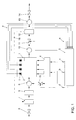
In Fig. 1 ist ein Dieselmotor 1 mit vier Brennräumen bzw. Zylindern 2 dargestellt.1 shows a
Dem Dieselmotor 1 wird über einen Luftmassenmesser 6, einen Verdichter (Kompressor)
7, einen Ladeluftkühler 8 und einen Einlassammler 9 die Ladeluft zugeführt. Über ein
Einspritzsystem 4 wird der Einspritzbeginn bzw. der Förderbeginn und die Fördermenge
eines entsprechenden Kraftstoffgemisches für die einzelnen Zylinder 2 des Dieselmotors
1 gesteuert. Das infolge der Verbrennungsvorgänge in den einzelnen Zylindern 2
auftretende Abgas wird von einem Abgassammler 10 gesammelt und einer Turbine 12
zugeführt, die über eine Turboladerwelle 16 mit dem Verdichter 7 verbunden ist. In Fig. 1
ist auch eine verstellbare Leitschaufel der Turbine 12 separat dargestellt. Der Turbine 12
ist eine Abgasanlage 13 nachgeschaltet, die das Abgas über ein Auslassrohr 14 ausgibt.
Das von dem Abgassammler 10 gesammelte Abgas wird über einen Rückführungspfad
zu dem Einlassammler 9 zurückgeführt. In diesem Abgasrückführungspfad ist ein Ventil
15 angeordnet, mit dessen Hilfe die Abgasrückführung gesteuert werden kann.The
In jedem Zylinder 2 des Dieselmotors 1 ist ein Drucksensor 3 angeordnet. Jeder
Drucksensor 3 besitzt beispielsweise eine flexible Membran, die abhängig von dem in
dem jeweiligen Zylinder herrschenden Zylinderdruck verbogen wird. Von jedem
Drucksensor 3 wird somit abhängig von der Verbiegung der entsprechenden
Druckmembran, d.h. abhängig von dem in dem jeweiligen Zylinder herrschenden
Zylinderdruck, ein entsprechendes Zylinderdrucksignal a erzeugt, welches einem
Motorsteuergerät 5 zugeführt wird.A
Das Motorsteuergerät 5 wertet die einzelnen Zylinderdrucksignale a aus, um davon
abhängig auf den Verbrennungsablauf in den entsprechenden Zylindern 2 zu schließen.
Die Auswertung der Zylinderdrucksignale a kann insbesondere kurbelwellenwinkelabhängig
erfolgen. Zu diesem Zweck ist ein (in Fig. 1 nicht gezeigter)
Kurbelwellensensor vorgesehen, der ein für die augenblickliche Stellung der Kurbelwelle
repräsentatives Ausgangssignal erzeugt und ebenfalls dem Motorsteuergerät 5 zuführt.
Durch die auf diese Weise durchgeführte Auswertung der Zylinderdrucksignale kann das
Motorsteuergerät 5 auf den in jedem Zylinder 2 herrschenden Verbrennungszustand
schließen und die in den einzelnen Zylindern 2 ablaufenden Verbrennungsvorgänge
entsprechend steuern. Hierzu erzeugt das Motorsteuergerät 5 nach Auswertung der
Zylinderdrucksignale a Stellsignale b, c, um somit die Einspritzmenge sowie den Einspritzbeginn
bzw. die Einspritzdauer des Kraftstoffgemisches für die einzelnen Zylinder 2
festzulegen.The
Unabhängig davon wertet das Motorsteuergerät 5 die einzelnen Zylinderdrucksignale a
auch aus, um auf den Ladedruck und den Abgasgegendruck des Dieselmotors 1 zu
schließen. Um eine zuverlässige Aussage über den Ladedruck und den
Abgasgegendruck zu erhalten, muss hierzu über mehrere Ladungswechselzyklen
gemittelt werden. In der Praxis hat es sich als ausreichend herausgestellt, wenn über
mindestens 40 Ladungswechselzyklen gemittelt wird.Regardless of this, the
In Fig. 2A ist der aus den gemittelten Zylinderdrucksignalen a abgeleitete Ladedruck gegenüber dem im Motorprüfstand tatsächlich gemessenen Ladedruck aufgetragen. Auch aus Fig. 2A ist ersichtlich, dass ein annähernd linearer Zusammenhang besteht, so dass aus den gemittelten Zylinderdrucksignalen a auf den Ladedruck geschlossen werden kann.2A is the boost pressure derived from the averaged cylinder pressure signals a plotted against the boost pressure actually measured in the engine test bench. 2A also shows that there is an approximately linear relationship, so that concludes from the averaged cylinder pressure signals a the boost pressure can be.
In Fig. 2B ist der aus den gemittelten Zylinderdrucksignalen a abgeleitete Abgasgegendruck gegenüber dem im Motorprüfstand tatsächlich gemessenen Abgasgegendruck aufgetragen. Fig. 2B kann entnommen werden, dass auch für den Abgasgegendruck ein annähernd linearer Zusammenhang besteht, so dass durch Anwendung eines entsprechenden linearen Modells aus den gemittelten Zylinderdrucksignalen a indirekt auf den Abgasgegendruck geschlossen werden kann.2B is that derived from the averaged cylinder pressure signals a Exhaust gas back pressure compared to that actually measured on the engine test bench Exhaust gas back pressure applied. Fig. 2B can be seen that also for the Exhaust gas back pressure has an almost linear relationship, so that by Application of a corresponding linear model from the averaged Cylinder pressure signals a can be concluded indirectly on the exhaust gas back pressure.
Nachdem das Motorsteuergerät 5 auf zuvor beschriebene Art und Weise auf den
Ladedruck und/oder Abgasgegendruck geschlossen hat, werden Stellsignale d bzw. e
zur Regelung des mit dem Abgasgegendruck korrelierenden Abgasrückführ-Massenstroms
in dem Rückführungspfad bzw. des Ladedrucks erzeugt. Das Stellsignal d
wird dem im Abgasrückführungspfad befindlichen Ventil 15 zugeführt, um auf diese
Weise den Abgasrückführ-Massenstrom, d.h. die Abgasrückführung, zu steuern. Je
stärker die Abgasrückführung ist, desto verschleppter wird die in den einzelnen Zylindern
2 des Dieselmotors 1 ablaufende Verbrennung. Das Stellsignal e wird hingegen der
verstellbaren Leitschaufel 11 der Turbine zugeführt, durch deren Verstellung der
Ladedruck entsprechend beeinflusst werden kann. After the
Da aus den gemittelten Zylinderdrucksignalen a mit Hilfe eines entsprechenden (linearen) Modells sowohl eine Aussage über den Ladedruck als auch eine Aussage über den Abgasgegendruck abhängig von dem jeweils betrachteten Kurbelwellenwinkelfenster gewonnen werden kann, sind bei der in Fig. 1 gezeigten Anordnung keine separaten Sensoren zur Erfassung des Ladedrucks bzw. Abgasgegendrucks erforderlich, so dass die damit verbundenen Kosten eingespart werden können. Since from the averaged cylinder pressure signals a with the help of a corresponding (linear) model, both a statement about the boost pressure and a statement about the exhaust gas back pressure depending on the crankshaft angle window considered in each case can be obtained, are not separate in the arrangement shown in Fig. 1 Sensors required to detect the boost pressure or exhaust gas back pressure, so that the associated costs can be saved.
- 11
- VerbrennungsmotorInternal combustion engine
- 22nd
- Zylindercylinder
- 33rd
- ZylinderdrucksensorCylinder pressure sensor
- 44th
- EinspritzsystemInjection system
- 55
- MotorsteuergerätEngine control unit
- 66
- LuftmassenmesserAir mass meter
- 77
- Verdichtercompressor
- 88th
- LadeluftkühlerIntercooler
- 99
- EinlassammlerInlet collector
- 1010th
- AbgassammlerExhaust collector
- 1111
- Leitschaufel der TurbineTurbine guide vane
- 1212th
- Turbineturbine
- 1313
- AbgasanlageExhaust system
- 1414
- AuslassrohrOutlet pipe
- 1515
- StellventilControl valve
- 1616
- TurboladerwelleTurbocharger shaft
- aa
- ZylinderdrucksignalCylinder pressure signal
- b-eb-e
- StellsignalControl signal
Claims (10)
Applications Claiming Priority (2)
| Application Number | Priority Date | Filing Date | Title |
|---|---|---|---|
| DE10028886 | 2000-06-10 | ||
| DE10028886A DE10028886A1 (en) | 2000-06-10 | 2000-06-10 | Method and device for monitoring the operation of an internal combustion engine |
Publications (3)
| Publication Number | Publication Date |
|---|---|
| EP1162357A2 true EP1162357A2 (en) | 2001-12-12 |
| EP1162357A3 EP1162357A3 (en) | 2002-07-17 |
| EP1162357B1 EP1162357B1 (en) | 2006-11-02 |
Family
ID=7645434
Family Applications (1)
| Application Number | Title | Priority Date | Filing Date |
|---|---|---|---|
| EP01112926A Expired - Lifetime EP1162357B1 (en) | 2000-06-10 | 2001-06-06 | Method and apparatus for monitoring the operations of an engine |
Country Status (2)
| Country | Link |
|---|---|
| EP (1) | EP1162357B1 (en) |
| DE (2) | DE10028886A1 (en) |
Cited By (7)
| Publication number | Priority date | Publication date | Assignee | Title |
|---|---|---|---|---|
| FR2833998A1 (en) * | 2001-12-20 | 2003-06-27 | Volkswagen Ag | I.c. engine recycled exhaust gas mass flow calculation procedure and apparatus uses measurements of pressure and fresh air temperature |
| WO2004048761A1 (en) * | 2002-11-27 | 2004-06-10 | Ricardo Uk Limited | Improved engine management |
| FR2871521A1 (en) * | 2004-06-11 | 2005-12-16 | Peugeot Citroen Automobiles Sa | Average and maximum gas pressure estimating system for diesel engine, has estimation unit for estimating average and maximum gas pressure in exhaust manifold according to pressure in cylinder of engine |
| EP1777397A1 (en) * | 2005-10-24 | 2007-04-25 | Renault s.a.s. | Method and system for estimating pressure in the intake manifold of an internal combustion engine |
| EP1830059A1 (en) * | 2004-10-07 | 2007-09-05 | Toyota Jidosha Kabushiki Kaisha | Device and method for controlling internal combustion engine |
| EP2754875A1 (en) * | 2013-01-15 | 2014-07-16 | Robert Bosch Gmbh | Method of operating a combustion engine |
| EP2910755A1 (en) | 2014-02-20 | 2015-08-26 | GE Jenbacher GmbH & Co OG | Method for operating a combustion engine |
Families Citing this family (4)
| Publication number | Priority date | Publication date | Assignee | Title |
|---|---|---|---|---|
| DE102006016905A1 (en) * | 2006-04-11 | 2007-10-25 | Daimlerchrysler Ag | Process for operating an internal combustion engine, especially for determining combustion chamber pressure, comprises modeling the combustion chamber pressure on previously determined operating variables |
| DE102009000149A1 (en) | 2009-01-12 | 2010-07-15 | Robert Bosch Gmbh | Method for determining e.g. mass flow of nitrogen oxide during operation of petrol engine of motor vehicle, involves determining temperature of gases present in chamber, and determining parameter depending on determined temperature |
| DE102015219133A1 (en) | 2015-10-02 | 2017-04-06 | Continental Automotive Gmbh | Method for operating an internal combustion engine for a motor vehicle and system for an internal combustion engine |
| DE102019213092A1 (en) * | 2019-08-30 | 2021-03-04 | Volkswagen Aktiengesellschaft | Method for diagnosing misfires in an internal combustion engine |
Citations (5)
| Publication number | Priority date | Publication date | Assignee | Title |
|---|---|---|---|---|
| US3930221A (en) * | 1973-03-09 | 1975-12-30 | Frank Thing | Exhaust backpressure warning system |
| JPH05180019A (en) * | 1991-12-27 | 1993-07-20 | Mitsubishi Motors Corp | Automobile engine |
| DE4443517A1 (en) * | 1993-12-14 | 1995-06-22 | Bosch Gmbh Robert | Load sensing device for internal combustion engine |
| US5794605A (en) * | 1995-03-07 | 1998-08-18 | Sanshin Kogyo Kabushiki Kaisha | Fuel control for marine engine |
| DE10002112A1 (en) * | 2000-01-19 | 2001-08-02 | Bosch Gmbh Robert | Diagnosing fuel supply system for internal combustion engine involves driving fuel delivery units feeding fuel from reservoir tank to engine depending on detected engine operating parameters |
Family Cites Families (6)
| Publication number | Priority date | Publication date | Assignee | Title |
|---|---|---|---|---|
| JPS58217723A (en) * | 1982-06-09 | 1983-12-17 | Fuji Heavy Ind Ltd | Supercharging pressure control device for engine equipped with supercharger |
| JPH03233162A (en) * | 1990-02-06 | 1991-10-17 | Mitsubishi Electric Corp | Combustion control device of internal combustion engine |
| DE4214648A1 (en) * | 1992-05-02 | 1993-11-04 | Bosch Gmbh Robert | SYSTEM FOR CONTROLLING AN INTERNAL COMBUSTION ENGINE |
| DE4326949C2 (en) * | 1993-08-11 | 1997-08-07 | Opel Adam Ag | Management system for piston internal combustion engines, in particular gasoline engines of motor vehicles |
| DE19539919C2 (en) * | 1994-10-26 | 1998-08-13 | Hitachi Ltd | In-cylinder pressure sensing device for multi-cylinder engines |
| JP3323974B2 (en) * | 1995-02-24 | 2002-09-09 | 株式会社ユニシアジェックス | Control device for internal combustion engine |
-
2000
- 2000-06-10 DE DE10028886A patent/DE10028886A1/en not_active Withdrawn
-
2001
- 2001-06-06 DE DE50111343T patent/DE50111343D1/en not_active Expired - Lifetime
- 2001-06-06 EP EP01112926A patent/EP1162357B1/en not_active Expired - Lifetime
Patent Citations (5)
| Publication number | Priority date | Publication date | Assignee | Title |
|---|---|---|---|---|
| US3930221A (en) * | 1973-03-09 | 1975-12-30 | Frank Thing | Exhaust backpressure warning system |
| JPH05180019A (en) * | 1991-12-27 | 1993-07-20 | Mitsubishi Motors Corp | Automobile engine |
| DE4443517A1 (en) * | 1993-12-14 | 1995-06-22 | Bosch Gmbh Robert | Load sensing device for internal combustion engine |
| US5794605A (en) * | 1995-03-07 | 1998-08-18 | Sanshin Kogyo Kabushiki Kaisha | Fuel control for marine engine |
| DE10002112A1 (en) * | 2000-01-19 | 2001-08-02 | Bosch Gmbh Robert | Diagnosing fuel supply system for internal combustion engine involves driving fuel delivery units feeding fuel from reservoir tank to engine depending on detected engine operating parameters |
Non-Patent Citations (1)
| Title |
|---|
| PATENT ABSTRACTS OF JAPAN vol. 017, no. 604 (M-1506), 8. November 1993 (1993-11-08) & JP 05 180019 A (MITSUBISHI MOTORS CORP), 20. Juli 1993 (1993-07-20) * |
Cited By (13)
| Publication number | Priority date | Publication date | Assignee | Title |
|---|---|---|---|---|
| FR2833998A1 (en) * | 2001-12-20 | 2003-06-27 | Volkswagen Ag | I.c. engine recycled exhaust gas mass flow calculation procedure and apparatus uses measurements of pressure and fresh air temperature |
| WO2004048761A1 (en) * | 2002-11-27 | 2004-06-10 | Ricardo Uk Limited | Improved engine management |
| FR2871521A1 (en) * | 2004-06-11 | 2005-12-16 | Peugeot Citroen Automobiles Sa | Average and maximum gas pressure estimating system for diesel engine, has estimation unit for estimating average and maximum gas pressure in exhaust manifold according to pressure in cylinder of engine |
| EP1607605A1 (en) * | 2004-06-11 | 2005-12-21 | Peugeot Citroen Automobiles SA | Pressure estimating system in the exhaust manifold of a diesel engine and method for calibrating said system |
| EP1830059A1 (en) * | 2004-10-07 | 2007-09-05 | Toyota Jidosha Kabushiki Kaisha | Device and method for controlling internal combustion engine |
| EP1830059A4 (en) * | 2004-10-07 | 2011-10-19 | Toyota Motor Co Ltd | Device and method for controlling internal combustion engine |
| FR2892453A1 (en) * | 2005-10-24 | 2007-04-27 | Renault Sas | METHOD AND DEVICE FOR ESTIMATING REGULATING PRESSURE IN THE INTAKE MANIFOLD OF AN INTERNAL COMBUSTION ENGINE |
| EP1777397A1 (en) * | 2005-10-24 | 2007-04-25 | Renault s.a.s. | Method and system for estimating pressure in the intake manifold of an internal combustion engine |
| EP2754875A1 (en) * | 2013-01-15 | 2014-07-16 | Robert Bosch Gmbh | Method of operating a combustion engine |
| EP2910755A1 (en) | 2014-02-20 | 2015-08-26 | GE Jenbacher GmbH & Co OG | Method for operating a combustion engine |
| AT515499A1 (en) * | 2014-02-20 | 2015-09-15 | Ge Jenbacher Gmbh & Co Og | Method for operating an internal combustion engine |
| AT515499B1 (en) * | 2014-02-20 | 2016-01-15 | Ge Jenbacher Gmbh & Co Og | Method for operating an internal combustion engine |
| US10161320B2 (en) | 2014-02-20 | 2018-12-25 | Ge Jenbacher Gmbh & Co Og | Method of operating an internal combustion engine |
Also Published As
| Publication number | Publication date |
|---|---|
| DE50111343D1 (en) | 2006-12-14 |
| EP1162357A3 (en) | 2002-07-17 |
| EP1162357B1 (en) | 2006-11-02 |
| DE10028886A1 (en) | 2001-12-13 |
Similar Documents
| Publication | Publication Date | Title |
|---|---|---|
| DE102007036258B4 (en) | Method and device for operating an internal combustion engine | |
| DE102008027762B3 (en) | Method and device for diagnosing an intake tract of an internal combustion engine | |
| DE602004001100T2 (en) | Exhaust control device of an internal combustion engine and method for estimating the exhaust gas flow | |
| DE102005056517A1 (en) | Compressor e.g. exhaust gas turbocharger, rotation speed determining method for use in e.g. diesel internal combustion engine, involves obtaining rotation speed of compressor from periodic fluctuation of portion of pressure signal | |
| DE102008056337A1 (en) | Internal combustion engine, particularly diesel engine or gasoline engine, has fresh air system, in which intercooler is arranged, and circumventive intercooler bypass is arranged in intercooler of fresh air system | |
| DE102006021091B3 (en) | Method and device for diagnosing the effectiveness of an exhaust gas catalytic converter | |
| DE102016219781A1 (en) | Method and control unit for balancing and diagnosing an exhaust gas recirculation mass flow meter | |
| EP1162357B1 (en) | Method and apparatus for monitoring the operations of an engine | |
| DE10232337A1 (en) | Method and device for monitoring an air mass measuring device | |
| WO2016058775A1 (en) | Method for monitoring the secondary air system in an exhaust gas purification system of an internal combustion engine | |
| WO2019120904A1 (en) | Method and device for determining the degree of fouling of an air filter of an internal combustion engine | |
| DE102008005958A1 (en) | Method and device for identifying a faulty pressure sensor in an intake tract of an internal combustion engine | |
| EP1609970B1 (en) | Method and device to operate an internal combustion engine | |
| DE102004038733A1 (en) | Method and device for operating an internal combustion engine | |
| DE102009055120B4 (en) | Method for checking a function of an actuator or a sensor, method for calibrating an actuator or a sensor and corresponding device | |
| WO2007087905A1 (en) | Method for monitoring the secondary air system in an exhaust-gas purification system | |
| DE10111775B4 (en) | Method and device for determining the gas outlet temperature of the turbine of an exhaust gas turbocharger of a motor vehicle | |
| DE10233951B4 (en) | Method for adapting a parking space model for an exhaust gas turbocharger | |
| DE10238288B4 (en) | Method for diagnosing an exhaust gas turbocharger actuator | |
| WO2013034393A1 (en) | Method for controlling an exhaust system of a diesel engine and exhaust system of a diesel engine | |
| DE10124596B4 (en) | Method and devices for determining the gas outlet temperature or gas inlet temperature of an internal combustion engine | |
| DE10162970B4 (en) | Method and device for determining the exhaust gas recirculation mass flow of an internal combustion engine | |
| WO2016202481A1 (en) | Method and device for determining the load condition of an exhaust gas particulate filter | |
| DE102007058234A1 (en) | Internal-combustion engine e.g. petrol engine, operating method for vehicle, involves adjusting supplied amount of air to combustion chamber of internal-combustion engine until measured value is adjusted to modeled value | |
| DE102008008209A1 (en) | Method for diagnosing intake-manifold switching in internal combustion engine, involves adjusting length of suction manifold in different operating areas in different manner |
Legal Events
| Date | Code | Title | Description |
|---|---|---|---|
| PUAI | Public reference made under article 153(3) epc to a published international application that has entered the european phase |
Free format text: ORIGINAL CODE: 0009012 |
|
| AK | Designated contracting states |
Kind code of ref document: A2 Designated state(s): AT BE CH CY DE DK ES FI FR GB GR IE IT LI LU MC NL PT SE TR |
|
| AX | Request for extension of the european patent |
Free format text: AL;LT;LV;MK;RO;SI |
|
| PUAL | Search report despatched |
Free format text: ORIGINAL CODE: 0009013 |
|
| AK | Designated contracting states |
Kind code of ref document: A3 Designated state(s): AT BE CH CY DE DK ES FI FR GB GR IE IT LI LU MC NL PT SE TR |
|
| AX | Request for extension of the european patent |
Free format text: AL;LT;LV;MK;RO;SI |
|
| 17P | Request for examination filed |
Effective date: 20030117 |
|
| AKX | Designation fees paid |
Designated state(s): DE ES FR GB IT |
|
| GRAP | Despatch of communication of intention to grant a patent |
Free format text: ORIGINAL CODE: EPIDOSNIGR1 |
|
| GRAS | Grant fee paid |
Free format text: ORIGINAL CODE: EPIDOSNIGR3 |
|
| GRAA | (expected) grant |
Free format text: ORIGINAL CODE: 0009210 |
|
| AK | Designated contracting states |
Kind code of ref document: B1 Designated state(s): DE ES FR GB IT |
|
| REG | Reference to a national code |
Ref country code: GB Ref legal event code: FG4D Free format text: NOT ENGLISH |
|
| REF | Corresponds to: |
Ref document number: 50111343 Country of ref document: DE Date of ref document: 20061214 Kind code of ref document: P |
|
| PG25 | Lapsed in a contracting state [announced via postgrant information from national office to epo] |
Ref country code: ES Free format text: LAPSE BECAUSE OF FAILURE TO SUBMIT A TRANSLATION OF THE DESCRIPTION OR TO PAY THE FEE WITHIN THE PRESCRIBED TIME-LIMIT Effective date: 20070213 |
|
| GBT | Gb: translation of ep patent filed (gb section 77(6)(a)/1977) |
Effective date: 20070129 |
|
| ET | Fr: translation filed | ||
| PLBE | No opposition filed within time limit |
Free format text: ORIGINAL CODE: 0009261 |
|
| STAA | Information on the status of an ep patent application or granted ep patent |
Free format text: STATUS: NO OPPOSITION FILED WITHIN TIME LIMIT |
|
| 26N | No opposition filed |
Effective date: 20070803 |
|
| PGFP | Annual fee paid to national office [announced via postgrant information from national office to epo] |
Ref country code: GB Payment date: 20070521 Year of fee payment: 7 |
|
| PGFP | Annual fee paid to national office [announced via postgrant information from national office to epo] |
Ref country code: IT Payment date: 20070620 Year of fee payment: 7 |
|
| PGFP | Annual fee paid to national office [announced via postgrant information from national office to epo] |
Ref country code: FR Payment date: 20070605 Year of fee payment: 7 |
|
| GBPC | Gb: european patent ceased through non-payment of renewal fee |
Effective date: 20080606 |
|
| REG | Reference to a national code |
Ref country code: FR Ref legal event code: ST Effective date: 20090228 |
|
| PG25 | Lapsed in a contracting state [announced via postgrant information from national office to epo] |
Ref country code: GB Free format text: LAPSE BECAUSE OF NON-PAYMENT OF DUE FEES Effective date: 20080606 |
|
| PG25 | Lapsed in a contracting state [announced via postgrant information from national office to epo] |
Ref country code: FR Free format text: LAPSE BECAUSE OF NON-PAYMENT OF DUE FEES Effective date: 20080630 Ref country code: IT Free format text: LAPSE BECAUSE OF NON-PAYMENT OF DUE FEES Effective date: 20080606 |
|
| PGFP | Annual fee paid to national office [announced via postgrant information from national office to epo] |
Ref country code: DE Payment date: 20170630 Year of fee payment: 17 |
|
| REG | Reference to a national code |
Ref country code: DE Ref legal event code: R119 Ref document number: 50111343 Country of ref document: DE |
|
| PG25 | Lapsed in a contracting state [announced via postgrant information from national office to epo] |
Ref country code: DE Free format text: LAPSE BECAUSE OF NON-PAYMENT OF DUE FEES Effective date: 20190101 |