EP1605729A2 - Electrically heated window - Google Patents
Electrically heated window Download PDFInfo
- Publication number
- EP1605729A2 EP1605729A2 EP05252357A EP05252357A EP1605729A2 EP 1605729 A2 EP1605729 A2 EP 1605729A2 EP 05252357 A EP05252357 A EP 05252357A EP 05252357 A EP05252357 A EP 05252357A EP 1605729 A2 EP1605729 A2 EP 1605729A2
- Authority
- EP
- European Patent Office
- Prior art keywords
- window
- heating element
- viewing area
- plies
- windscreen
- Prior art date
- Legal status (The legal status is an assumption and is not a legal conclusion. Google has not performed a legal analysis and makes no representation as to the accuracy of the status listed.)
- Granted
Links
Images


Classifications
-
- B—PERFORMING OPERATIONS; TRANSPORTING
- B32—LAYERED PRODUCTS
- B32B—LAYERED PRODUCTS, i.e. PRODUCTS BUILT-UP OF STRATA OF FLAT OR NON-FLAT, e.g. CELLULAR OR HONEYCOMB, FORM
- B32B17/00—Layered products essentially comprising sheet glass, or glass, slag, or like fibres
- B32B17/06—Layered products essentially comprising sheet glass, or glass, slag, or like fibres comprising glass as the main or only constituent of a layer, next to another layer of a specific material
- B32B17/10—Layered products essentially comprising sheet glass, or glass, slag, or like fibres comprising glass as the main or only constituent of a layer, next to another layer of a specific material of synthetic resin
- B32B17/10005—Layered products essentially comprising sheet glass, or glass, slag, or like fibres comprising glass as the main or only constituent of a layer, next to another layer of a specific material of synthetic resin laminated safety glass or glazing
- B32B17/1055—Layered products essentially comprising sheet glass, or glass, slag, or like fibres comprising glass as the main or only constituent of a layer, next to another layer of a specific material of synthetic resin laminated safety glass or glazing characterized by the resin layer, i.e. interlayer
- B32B17/10761—Layered products essentially comprising sheet glass, or glass, slag, or like fibres comprising glass as the main or only constituent of a layer, next to another layer of a specific material of synthetic resin laminated safety glass or glazing characterized by the resin layer, i.e. interlayer containing vinyl acetal
-
- B—PERFORMING OPERATIONS; TRANSPORTING
- B32—LAYERED PRODUCTS
- B32B—LAYERED PRODUCTS, i.e. PRODUCTS BUILT-UP OF STRATA OF FLAT OR NON-FLAT, e.g. CELLULAR OR HONEYCOMB, FORM
- B32B17/00—Layered products essentially comprising sheet glass, or glass, slag, or like fibres
- B32B17/06—Layered products essentially comprising sheet glass, or glass, slag, or like fibres comprising glass as the main or only constituent of a layer, next to another layer of a specific material
- B32B17/10—Layered products essentially comprising sheet glass, or glass, slag, or like fibres comprising glass as the main or only constituent of a layer, next to another layer of a specific material of synthetic resin
- B32B17/10005—Layered products essentially comprising sheet glass, or glass, slag, or like fibres comprising glass as the main or only constituent of a layer, next to another layer of a specific material of synthetic resin laminated safety glass or glazing
- B32B17/10009—Layered products essentially comprising sheet glass, or glass, slag, or like fibres comprising glass as the main or only constituent of a layer, next to another layer of a specific material of synthetic resin laminated safety glass or glazing characterized by the number, the constitution or treatment of glass sheets
- B32B17/10036—Layered products essentially comprising sheet glass, or glass, slag, or like fibres comprising glass as the main or only constituent of a layer, next to another layer of a specific material of synthetic resin laminated safety glass or glazing characterized by the number, the constitution or treatment of glass sheets comprising two outer glass sheets
-
- B—PERFORMING OPERATIONS; TRANSPORTING
- B32—LAYERED PRODUCTS
- B32B—LAYERED PRODUCTS, i.e. PRODUCTS BUILT-UP OF STRATA OF FLAT OR NON-FLAT, e.g. CELLULAR OR HONEYCOMB, FORM
- B32B17/00—Layered products essentially comprising sheet glass, or glass, slag, or like fibres
- B32B17/06—Layered products essentially comprising sheet glass, or glass, slag, or like fibres comprising glass as the main or only constituent of a layer, next to another layer of a specific material
- B32B17/10—Layered products essentially comprising sheet glass, or glass, slag, or like fibres comprising glass as the main or only constituent of a layer, next to another layer of a specific material of synthetic resin
- B32B17/10005—Layered products essentially comprising sheet glass, or glass, slag, or like fibres comprising glass as the main or only constituent of a layer, next to another layer of a specific material of synthetic resin laminated safety glass or glazing
- B32B17/10165—Functional features of the laminated safety glass or glazing
- B32B17/10174—Coatings of a metallic or dielectric material on a constituent layer of glass or polymer
-
- H—ELECTRICITY
- H05—ELECTRIC TECHNIQUES NOT OTHERWISE PROVIDED FOR
- H05B—ELECTRIC HEATING; ELECTRIC LIGHT SOURCES NOT OTHERWISE PROVIDED FOR; CIRCUIT ARRANGEMENTS FOR ELECTRIC LIGHT SOURCES, IN GENERAL
- H05B3/00—Ohmic-resistance heating
- H05B3/84—Heating arrangements specially adapted for transparent or reflecting areas, e.g. for demisting or de-icing windows, mirrors or vehicle windshields
- H05B3/86—Heating arrangements specially adapted for transparent or reflecting areas, e.g. for demisting or de-icing windows, mirrors or vehicle windshields the heating conductors being embedded in the transparent or reflecting material
-
- H—ELECTRICITY
- H05—ELECTRIC TECHNIQUES NOT OTHERWISE PROVIDED FOR
- H05B—ELECTRIC HEATING; ELECTRIC LIGHT SOURCES NOT OTHERWISE PROVIDED FOR; CIRCUIT ARRANGEMENTS FOR ELECTRIC LIGHT SOURCES, IN GENERAL
- H05B2203/00—Aspects relating to Ohmic resistive heating covered by group H05B3/00
- H05B2203/002—Heaters using a particular layout for the resistive material or resistive elements
- H05B2203/003—Heaters using a particular layout for the resistive material or resistive elements using serpentine layout
-
- H—ELECTRICITY
- H05—ELECTRIC TECHNIQUES NOT OTHERWISE PROVIDED FOR
- H05B—ELECTRIC HEATING; ELECTRIC LIGHT SOURCES NOT OTHERWISE PROVIDED FOR; CIRCUIT ARRANGEMENTS FOR ELECTRIC LIGHT SOURCES, IN GENERAL
- H05B2203/00—Aspects relating to Ohmic resistive heating covered by group H05B3/00
- H05B2203/002—Heaters using a particular layout for the resistive material or resistive elements
- H05B2203/004—Heaters using a particular layout for the resistive material or resistive elements using zigzag layout
Definitions
- the present invention relates to an electrically heated window, and more particularly to a laminated window fitted with an imaging device which views an object to be imaged through a viewing area of the window.
- the invention finds particular application in windows for vehicles, e.g. where a camera is mounted on a windscreen to view the road ahead, or the surroundings of the vehicle.
- one approach adopted is to provide technical aids to drivers to assist them to drive safely.
- one such aid may monitor a vehicle's course relative to the road ahead, and alert the driver when deviations occur.
- a further possibility is to provide assistance to the driver in conditions of poor visibility due to adverse weather or low light levels, e.g. in fog or at night.
- Imaging devices for example a camera
- the functioning of such systems will be adversely affected if the image formed by the device is impaired in some way. Accordingly, one prerequisite is for the imaging device to have a clear view, free of condensation, frost, ice or snow on the window, regardless of weather conditions.
- US 5,804,817 relates to a rain sensor for detecting the degree of wetting of a window, especially a vehicle windscreen.
- the sensor relies on the attenuating effect of raindrops on radiation which follows a measurement path in the glass of a windscreen, undergoing several total internal reflections between the outer and inner surfaces of the glass.
- a heating device is arranged on at least one contact surface between the sensor and the window. In the principal embodiment of the invention, this takes the form of a non-transparent heated plate held in contact with the glass; alternatively, a heating wire may be provided adjacent the measurement path, e.g. in the sensor base, in a seal or on the glass.
- the rain sensor is not an image-forming device, and does not view an object through the glass.
- FR 2 841 488 discloses a detector, especially for mounting on the rear of a vehicle, to warn a driver of obstacles behind the vehicle when reversing. It contains a camera in a housing, the latter having a heated viewing window.
- JP 11-291869 discloses a housing for a camera, the housing having a heated window and also containing a light sensor and a thermostatic switch. When the measured temperature falls below a set temperature, the switch energises a heating circuit to heat the window. While effective, these systems add cost and complexity to the vehicle because of the additional housing required to accommodate the camera.
- a viewing area in a pre-existing vehicle window i.e. one that is routinely fitted to a vehicle, for example the windscreen or rear window, through which an imaging device may view an object, and which can be maintained clear throughout the period of operation of the device without excessive power consumption.
- the present invention accordingly provides an electrically heated window intended to be fitted with an imaging device which views an object to be imaged through a viewing area of the window, the window being laminated from at least two plies of glazing material and at least one ply of interlayer material extending between the plies of glazing material, the window comprising a resistance heating element arranged to heat a localised area of the window including the viewing area and electrical connection means for connecting the heating element to an electrical supply, wherein the heating element is laminated between the plies of glazing material.
- the window is in the passenger compartment of the vehicle, and is normally the windscreen or rear window.
- the heating element Laminating the heating element inside the window provides a durable and efficient means of directly heating the viewing area, as the heating element is protected from damage, and heating losses that occur at the contact between the heating plate known from US 5,804,817 and the windscreen are eliminated.
- the heating element may be on a ply of glazing material, or on a ply of interlayer material, or embedded within a ply ofinterlayer material.
- the invention also provides an electrically heated vehicle window intended to be fitted with an imaging device which views an object to be imaged through a viewing area of the window, the window comprising either a single sheet of glazing material or multiple sheets of glazing material laminated together, the window further comprising a resistance heating element arranged to heat a localised area of the window including the viewing area and electrical connection means for connecting the heating element to an electrical supply, wherein the heating element is printed in conductive ink on the surface of a sheet of glazing material.
- the heating element may be positioned within the viewing area, or adjacent it, so as not to affect the image viewed. In the latter case, the viewing area is heated by heat conducted from the heating element.
- This arrangement takes advantage of the fact that a heating element inevitably heats the surrounding area by conduction, and so if the viewing area is compact, it can be satisfactorily heated in this way.
- the invention also provides a window which is provided with a substantially opaque coating disposed on a face of at least one of the plies, and the substantially opaque coating extends over the edges of the heating element so as to obscure them from view. This provides an aesthetically preferable design.
- the window is a vehicle windscreen having mirror symmetry about a centre line, and the viewing area is positioned on the centre line, near the upper edge of the windscreen.
- a windscreen may be provided with a mirror boss for mounting a rear view mirror, in which case, the viewing area may adjoin the mirror boss.
- the window is provided with a wiper, and the viewing area is within the area wiped by the wiper. This ensures that the viewing area is also kept clear of raindrops and the dirt which inevitably accumulates on windows, especially on vehicles.
- the window includes an additional electrical resistance on or in the window and connected in series with the heating element, the value of the additional electrical resistance being selected to be complementary to the resistance of the heating element, so that application of the supply voltage across the total resistance results in a desired level of power density in the heating element.
- the heating element is normally quite small, there is only a short conductive path between the positive and negative electrical connection means to the heating element. Consequently the resistance of the heating element is generally low, and so the desired power density is dissipated by the heating element at a low voltage, often well below the normal supply voltage which is available, e.g. 12-14 V, and certainly below the 42 V value which will be used in future. It is therefore convenient to include an additional electrical resistance, within the circuit on the window, to balance that of the heating element, and allow the available supply voltage to be applied without further modification.
- a method of manufacturing the aforementioned electrically heated window comprising providing the heating element and the electrical connection means at the appropriate position between the plies of glazing material, and laminating the plies of glazing material and the ply of interlayer material together to form a laminated window.
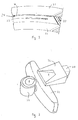
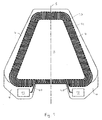
- FIG. 1 there is shown a general view of an electrically heated window 1 intended to be fitted with an imaging device, and the particular window shown is a windscreen for a vehicle.
- the imaging device would be mounted on the face of the windscreen which in use faces into the vehicle, and this will be referred to as the interior face of the windscreen.
- the face of the windscreen which in use forms part of the exterior surface of the vehicle will correspondingly be referred to as the exterior face.
- the imaging device forms an image of objects viewed through the windscreen, and the area of the windscreen through which the device views such objects is denoted the viewing area 2.
- a localised area 3 of the windscreen which includes viewing area 2, is heated by a heating element (Fig. 2) to keep it clear of condensation or ice, etc.
- the localised area 3 is small in comparison to the total area of the window, representing less than 10% of the area, and typically only 1 or 2% of the area.
- the window is provided with a substantially opaque coating 4, which is typically black, and in this case extends around the whole periphery of the windscreen to hide the flange of the vehicle bodywork on which the windscreen is mounted, and protect the adhesive from the adverse effect of ultraviolet light.
- the coating 4, which is commonly referred to as an obscuration band advantageously extends over the edges of the localised area 3 to obscure the edges of the heating element from view; but, needless to say, the obscuration band does not extend over the viewing area itself, an aperture or uncoated area being left over the viewing area.
- the obscuration band is printed using a ceramic ink which is fired during the same heating cycle as is used to bend the plies of glass to the required shape.
- the windscreen has a centre line 5 extending in a vertical plane, from the upper edge 6 of the windscreen to the lower edge 7 (references to the orientation of the windscreen are to be understood as assuming the windscreen is in its installed orientation).
- the windscreen has mirror symmetry about the centre line, as do most vehicles to at least a first approximation, and it is advantageous from both technical and aesthetic perspectives if the viewing area 2 is positioned on, or at least near to, the centre line 5.
- the viewing area is positioned near the upper edge 6 of the windscreen in order to benefit from the improved view afforded by a more elevated viewing position.
- the windscreen is provided with an attachment area 8 for a mirror boss on which a rear view mirror is mounted. It is convenient to arrange the viewing area 2 to adjoin the attachment area 8 for the mirror boss.
- the windscreen is also provided with windscreen wipers 9, which wipe an area 10 of the windscreen. It is advantageous if the viewing area is within the wiped area, as the exterior face of the portion of the windscreen occupied by the viewing area is thereby kept clean.
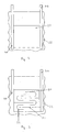
- Figure 2 is a section of part of the window of Figure 1, on the line II-II of Figure 1, and shows the laminated construction of the window. It comprises inner and outer plies of glazing material 20, 21, e.g. annealed glass, and a ply of interlayer material 22, e.g. polyvinylbutyral (PVB), which extends between the plies of glazing material.
- the obscuration band 4 is shown on the inner face 24 of the outer ply 21; alternatively, it could be provided on one of the faces of the inner ply 20.
- the heating element 23 is disposed between the plies of glazing material, and heats a localised area of the windscreen around it.
- the heating element may have a ply of interlayer on either or both sides of it, as will be explained in more detail below. Similarly, the various forms the heating element may take are explained in more detail below. It will be appreciated that the obscuration band 4 conceals the heating element 23 from external view; indeed, owing to the deep shadow cast by the obscuration band, the heating element will be barely detectable when viewed from the inside of the vehicle.
- Figure 3 is a perspective view of an imaging device 30 and a rear view mirror 31, as they might coexist on a windscreen.
- the imaging device is a form of camera, which may be used to view the surroundings of the vehicle, for instance the road on which the vehicle is travelling. In one application it is used to monitor the road ahead of the vehicle, e.g. the camera is aligned to view a line or other marking dividing two lanes or carriageways.
- the camera image is processed by appropriate image analysis software running on an onboard computer, which alerts the driver if the vehicle strays from the lane or carriageway it is following, e.g. due to driver fatigue or a distraction, a so-called "lane departure warning" system.
- the computer may initiate appropriate corrective action.
- the camera is mounted on a viewing bracket 32, which is attached to the windscreen and defines the viewing area 2.
- Figure 3 also shows the mirror boss attachment area 8, and the mirror boss 33 itself; it is convenient to mount the camera in the vicinity of the mirror boss 33, especially just above it, as this area of the windscreen is not used for vision by the driver, and it provides an elevated view for the camera 30.
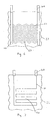
- FIG. 4 shows a resistance heating element according to a first embodiment of the invention.
- the heating element 23 comprises a carrier foil to which an electrically conductive thin film has been applied.
- the thin film may comprise one or more silver layers, or a conductive metal oxide, and the carrier film may be polyethylene terephthalate (PET) having a thickness in the range 40 to 100 ⁇ m.
- PET polyethylene terephthalate
- a preferred product of this type, having double silver layers, is designated XIR 75 and is available from Southwall Technologies Inc of Palo Alto, California.
- a piece of this material cut to the size of heating element required, is placed between two plies of PVB, each preferably 0.38 mm thick to minimise the total thickness of material which has to be accommodated between the plies of glazing material.
- the two plies of interlayer flow and fuse together, so that in the sectional view of Figure 2, the heating element appears to occupy a position partway through the thickness of a single ply of PVB.
- Electrical connection means 40 are provided for connecting the heating element to the vehicle electrical supply.
- one of the plies of PVB may carry busbars for supply of electrical power, and the busbars may comprise thin copper foils or strips, which are connected to the vehicle electrical supply in known fashion by conventional wires and terminals.
- the power density at which the heating element is operated should be selected to release sufficient heat to melt ice within an acceptable time period, and prevent the formation of condensation during use, while not consuming excessive power or causing damage. Suitable power densities have been found to be in the range 200 - 3000 Wm -2 , preferably 200 - 2500 Wm -2 . If the heating element is to be powered continuously, a power density in the range 400 - 1000 Wm -2 is preferred so that the maximum temperature attained is not excessive. On the other hand, in some applications a rapid heating response is desired, in which case a power density in the range 1500 - 3000 Wm -2 may be employed together with, where appropriate, a temperature sensor and switching circuit to avoid dangerously high temperatures being attained. One example of an application where a high power density is desirable is where the heating element is adjacent, as opposed to within, the viewing area.
- the path length from one busbar to the other is relatively short, which means that the heating element has a relatively low resistance, and the desired power density is achieved at a relatively low voltage.
- Figure 5 shows a second embodiment of heating element in which the path length from one busbar to the other is increased.
- the heating element 50 which is still based on a piece of coated PET as before, is treated to produce divisions or splits 51 in the conductive layer.
- Suitable treatment techniques include etching by laser to selectively remove predetermined areas of coating, or mechanical stamping to cut the coating where desired. As such divisions tend to result in increased current densities at the apices of the divisions, producing hot spots, further divisions 52 may be included to alleviate such hot spots.
- FIG. 6 shows a third embodiment of heating element for the viewing area of a window.
- This heating element 60 employs thin tungsten wires 61 to provide the heating circuit.
- the wires are typically 15-50 ⁇ m thick, and are laid 1.8-3.0 mm apart; they may be crimped (as illustrated) to reduce unwanted reflections, or straight.
- a preferred way of manufacturing such heating elements efficiently is to use the drum machine disclosed in EP-A-788 294. Numerous pieces of PVB are cut to size, and copper strips are laid on them in position to form busbars, held in place by local application of heat, e.g. from a soldering iron. The pieces of PVB are then placed side-by-side on the drum, and all wired in one operation.
- the pieces are separated by cutting the wires between them, and each piece is used as a heating element.
- the heating element may be placed on top of the full size ply of interlayer material 22, in which case it is preferable for the heating element to be formed on 0.38 mm thick PVB.
- an appropriately sized aperture may be cut in the full size interlayer ply, and the heating element inserted in the aperture, so that it replaces the piece of interlayer material which was removed.
- An alternative technique for providing busbars is to print them using conductive silver ink.
- the busbars may be printed on one of the faces of the glass plies which faces the interlayer after assembly, and the heating element may then be placed in direct contact with the glass ply so that the heating element makes electrical contact with the printed busbars.
- FIG. 7 shows a fourth embodiment of heating element, which again employs wires, but of a ductile metal such as copper, and the wires are arranged in boustrophedon manner.
- This heating element 70 comprises a single copper wire 71, which may be 0.08-0.2 mm in diameter, and extends along a switchback path comprising a series of 90° bends arranged to produce a square wave pattern. Alternatively, a serpentine pattern comprising a series of radiused 180° "hairpin" bends would be satisfactory. The spacing between adjacent portions of the wire may be 5-10 mm.
- Such a wire pattern is best laid with the PVB placed on a flat table, using a programmable robotic apparatus of the type used to deposit antenna wires. Prior to laminating, the wire may be held in position by application of a PVB solution, or use of heat.
- Figure 8 shows an alternative version of the invention, in which the window includes an additional electrical resistance.
- some of the embodiments of heating element described above have relatively low resistances, and develop the desired power density on application of a relatively low voltage. It would be convenient for the electrically heated window to be connected to the same supply voltage as other components in the same vehicle, i.e. without having to modify the supply voltage for the window.
- an additional electrical resistance is provided on or in the window and connected in series with the heating element, the value of the additional electrical resistance being selected to be complementary to the resistance of the heating element, so that application of the supply voltage across the total resistance results in a desired level of power density in the heating element.
- an electrically heated window 80 is shown, which is provided with a localised area 81 heated by a heating element as before.
- the electrical connection means led directly from the heating element to the edge of the window, and then passed outside the window to allow connection to be made
- an additional resistance 82 is connected in series with the heating element on each side of the element.
- the window has an obscuration band 83, and it is aesthetically preferable if the additional resistances are concealed from view by the obscuration band.
- the additional resistances may take the form of a convoluted line 84 printed in silver ink on the obscuration band, or a similarly convoluted wire laid on a ply which is on the interior side of the obscuration band, and hence concealed by it.
- the electrical connection means 40 are connected to the ends of the additional resistances, rather than directly to the heating element itself.
- Figure 9 shows a fifth embodiment of heating element 90 which is printed onto one of the plies or sheets of glazing material, adjacent the viewing area 2.
- the element may be provided on an internal face, i.e. a face which is adjacent the interlayer in the assembled laminate, or on an exposed face.
- the heating element comprises one or more conductive lines 91 which may be printed in a conductive ink or enamel.
- the ink contains silver, and preferably the glazing material is glass, in which case the ink may be frit-based so that it may be fired onto the glass in known manner. Further preferably, the ink is screen-printed, allowing great flexibility in the pattern of lines applied to the glazing material.
- a preferred pattern is the boustrophedon pattern shown, in which a conductive line comprises alternate U-shaped bends interspersed with straight or moderately curved segments, so that the line progresses in alternately left to right then right to left directions.
- This pattern allows high heat generation within a compact area, so that sufficient heat is generated for the whole of the viewing area 2 to be heated by thermal conduction from the element.
- the heating element is shown provided with connector pads 92 for connection of the electrical supply, e.g. by soldered terminals or pressure contacts, when the element is on an exposed face.
- the connector pads may be omitted and the electrical connection means 40 comprising a printed conductive track may be extended to join or form a busbar, normally also printed and positioned adjacent the edge of the window.
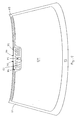
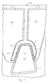
- Figure 10 shows a windscreen 100 having both a heated localised area 103 including part of a viewing area 102 for an imaging device and a heated wiper rest area 111.
- the localised area is heated by a resistance heating element 101 in the form of one or more screen printed lines of conductive ink.
- a substantially opaque coating 104 forming an obscuration band.
- the window has an upper edge 106 and a lower edge 107.
- the heated viewing area 102 and heated wiper rest area 111 share common electrical connection points 108 adjacent lower edge 107; the heated viewing area 102 is supplied with electrical power by electrical connection means in the form of extended conductors or busbars 109.
- the viewing area 102 is delimited by an area 110 which represents the contact area of a housing for an imaging device such as a camera when affixed to the windscreen.
- Figure 11 is an enlargement of the heated viewing area 102 of Figure 10 and the surrounding part of the windscreen, showing more clearly the heating element 101 which forms part of the heating circuit for heating the viewing area.
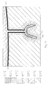
- Figure 12 shows part of the busbars 109 and the heating element 101 together with thermal contours calculated in a thermal simulation of steady state operation of the heating circuit.
- the simulation assumed an applied voltage of 12V and an ambient temperature of 20°C.
- Using a busbar width of 4mm and a conductive line width of 1.27mm together with a silver ink resistance of 3.5 milliohms per square resulted in a circuit resistance of 4.4 ohms and an average power density of 2000 Wm -2 .
- the thermal contours reveal the actual area heated in practice by the circuit, which is sufficient to dispel condensation, frost, snow and ice from the viewing area.
Abstract
Description
Claims (16)
- An electrically heated window intended to be fitted with an imaging device which views an object to be imaged through a viewing area of the window, the window being laminated from at least two plies of glazing material and at least one ply of interlayer material extending between the plies of glazing material, the window comprising a resistance heating element arranged to heat a localised area of the window including the viewing area and electrical connection means for connecting the heating element to an electrical supply, wherein the heating element is laminated between the plies of glazing material.
- An electrically heated vehicle window intended to be fitted with an imaging device which views an object to be imaged through a viewing area of the window, the window comprising either a single ply of glazing material or multiple plies of glazing material laminated together, the window further comprising a resistance heating element arranged to heat a localised area of the window including the viewing area and electrical connection means for connecting the heating element to an electrical supply, wherein the heating element is printed in conductive ink on the surface of a ply of glazing material.
- A window as claimed in claim 1 or claim 2, wherein the heating element is positioned within the viewing area.
- A window as claimed in claim 1 or claim 2, wherein the heating element is positioned adjacent the viewing area.
- A window as claimed in any preceding claim, wherein the window is provided with a substantially opaque coating disposed on a face of at least one of the plies, and the substantially opaque coating extends over the edges of the heating element so as to obscure them from view.
- A window as claimed in any preceding claim, wherein the window is a vehicle windscreen having mirror symmetry about a centre line, and the viewing area is positioned on the centre line, near the upper edge of the windscreen.
- A window as claimed in any preceding claim, wherein the windscreen is provided with a mirror boss for mounting a rear view mirror, and the viewing area adjoins the mirror boss.
- A window as claimed in any preceding claim, wherein the window is provided with a wiper, and the viewing area is within the area wiped by the wiper.
- A window as claimed in any preceding claim, wherein the window includes an additional electrical resistance on or in the window and connected in series with the heating element, the value of the additional electrical resistance being selected to be complementary to the resistance of the heating element, so that application of the supply voltage across the total resistance results in a desired level of power density in the heating element.
- A window as claimed in any preceding claim, wherein the heating element has a power density in the range 200 - 3000 Wm-2, preferably 200 - 2500 Wm-2.
- A window as claimed in any preceding claim, wherein the window is for a road vehicle, and the imaging device is a camera for viewing the road on which the vehicle is travelling.
- A window as claimed in any preceding claim, having an imaging device attached to the window and arranged to view an object through the viewing area of the window.
- A window as claimed in any preceding claim, in which the heating element comprises conductive wires or lines arranged in boustrophedon manner.
- A method of manufacturing the electrically heated window of claim 1, comprising providing the heating element and the electrical connection means at the appropriate position between the plies of glazing material, and laminating the plies of glazing material and the ply of interlayer material together to form a laminated window.
- A method as claimed in claim 14, comprising placing the heating element between two plies of interlayer material.
- A method as claimed in claim 14 or claim 15, comprising assembling the heating element on a piece of interlayer material, cutting out a corresponding piece of interlayer material from the ply of interlayer material and replacing it with the piece carrying the heating element.
Applications Claiming Priority (2)
| Application Number | Priority Date | Filing Date | Title |
|---|---|---|---|
| GB0408392 | 2004-04-15 | ||
| GBGB0408392.9A GB0408392D0 (en) | 2004-04-15 | 2004-04-15 | Electrically heated window |
Publications (3)
| Publication Number | Publication Date |
|---|---|
| EP1605729A2 true EP1605729A2 (en) | 2005-12-14 |
| EP1605729A3 EP1605729A3 (en) | 2007-09-05 |
| EP1605729B1 EP1605729B1 (en) | 2018-07-18 |
Family
ID=32320860
Family Applications (1)
| Application Number | Title | Priority Date | Filing Date |
|---|---|---|---|
| EP05252357.8A Revoked EP1605729B1 (en) | 2004-04-15 | 2005-04-15 | Electrically heated window |
Country Status (2)
| Country | Link |
|---|---|
| EP (1) | EP1605729B1 (en) |
| GB (1) | GB0408392D0 (en) |
Cited By (61)
| Publication number | Priority date | Publication date | Assignee | Title |
|---|---|---|---|---|
| FR2896698A1 (en) * | 2006-02-02 | 2007-08-03 | Vygon Sa | NEUROSTIMULATION CATHETER AND ITS BASE |
| WO2009012771A1 (en) | 2007-07-26 | 2009-01-29 | Adc Automotive Distance Control Systems Gmbh | Viewing window for the arrangement of an optical sensor and/or detection system in a vehicle |
| EP2071901A1 (en) | 2007-12-11 | 2009-06-17 | Ford Global Technologies, LLC | Window with resistance heating element |
| DE102008003219A1 (en) | 2008-01-04 | 2009-07-09 | Saint-Gobain Sekurit Deutschland Gmbh & Co. Kg | Glass pane and glass pane arrangement |
| WO2010043598A1 (en) * | 2008-10-15 | 2010-04-22 | Saint-Gobain Glass France | Transparent object with a locally limited, structured, electrically heatable transparent area, method for the manufacture thereof and use thereof |
| EP2206601A1 (en) * | 2009-01-08 | 2010-07-14 | Saint Gobain Glass France | Plate with a function element |
| DE102009004045A1 (en) * | 2009-01-08 | 2010-07-22 | Saint-Gobain Sekurit Deutschland Gmbh & Co. Kg | Disk i.e. windscreen, for e.g. aircraft, has daylight blocker exhibiting transmission for light of preset wavelength less than preset percentage and for light of wavelength of preset greater than preset percentage |
| EP2257120A2 (en) * | 2008-03-17 | 2010-12-01 | LG Chem, Ltd. | Heating element and manufacturing method for same |
| WO2010149649A1 (en) | 2009-06-24 | 2010-12-29 | Saint-Gobain Glass France | Disc with a heatable, optically transparent sensor array |
| EP2275389A2 (en) * | 2008-03-17 | 2011-01-19 | LG Chem, Ltd. | Heater and manufacturing method for same |
| US20110017719A1 (en) * | 2008-03-17 | 2011-01-27 | Hyeon Choi | Heater and manufacturing method for same |
| WO2011015551A1 (en) | 2009-08-04 | 2011-02-10 | Saint-Gobain Glass France | Panel having optically transparent sensor field |
| CN101978776A (en) * | 2008-03-17 | 2011-02-16 | Lg化学株式会社 | Heating element and manufacturing method for same |
| US20110108537A1 (en) * | 2008-04-10 | 2011-05-12 | Schall Guenther | Transparent window with a heatable coating and low-impedance conducting structures |
| EP2325002A1 (en) | 2009-11-17 | 2011-05-25 | Saint-Gobain Glass France | Method for producing a laminated glass pane with sensor window |
| WO2011069901A1 (en) | 2009-12-11 | 2011-06-16 | Saint-Gobain Glass France | Coated disk having a heatable communication window |
| DE202009018502U1 (en) | 2009-06-24 | 2011-12-22 | Saint-Gobain Sekurit Deutschland Gmbh & Co. Kg | Disc with heatable, optically transparent sensor field |
| DE102010052472A1 (en) * | 2010-11-26 | 2012-05-31 | Calesco/Backer Bhv Ab | Arrangement for an image acquisition device in a vehicle |
| EP2584864A1 (en) * | 2011-10-20 | 2013-04-24 | Peter Bäumler | Heatable glazing panel |
| EP2586610A1 (en) | 2011-10-27 | 2013-05-01 | Saint-Gobain Glass France | Sheet with high frequency transmission |
| WO2013131698A1 (en) | 2012-03-05 | 2013-09-12 | Saint-Gobain Glass France | Process for producing a laminated glass pane with sensor window |
| WO2013131700A1 (en) | 2012-03-05 | 2013-09-12 | Saint-Gobain Glass France | Pane arrangement having an electrically heatable baffle plate |
| EP2963995A1 (en) * | 2014-07-03 | 2016-01-06 | United Technologies Corporation | Heating circuit assembly and method of manufacture |
| DE102014220431A1 (en) | 2014-10-09 | 2016-04-14 | Conti Temic Microelectronic Gmbh | Method for removing weather-related deposits on a vehicle window pane in the area of a camera view window |
| WO2016088472A1 (en) * | 2014-12-04 | 2016-06-09 | 日本板硝子株式会社 | Windshield and vehicle-mounted system |
| EP2127475B1 (en) | 2007-02-23 | 2016-06-29 | Saint-Gobain Glass France | Transparent glass with heating coating |
| EP3081378A1 (en) | 2012-10-15 | 2016-10-19 | Saint-Gobain Glass France | Pane with high frequency transmission |
| FR3042677A1 (en) * | 2015-10-15 | 2017-04-21 | Peugeot Citroen Automobiles Sa | GLAZING WITH IMPROVED DEFROSTING SYSTEM. |
| EP3168084A1 (en) * | 2015-11-11 | 2017-05-17 | Toyota Jidosha Kabushiki Kaisha | On-vehicle imaging device |
| JP2017081520A (en) * | 2015-10-30 | 2017-05-18 | 日本板硝子株式会社 | Windshield |
| JP2017147031A (en) * | 2016-02-15 | 2017-08-24 | トヨタ自動車株式会社 | Heater structure for periphery monitoring device |
| JP2017212148A (en) * | 2016-05-26 | 2017-11-30 | 日本板硝子株式会社 | Windshield |
| RU176268U1 (en) * | 2017-02-01 | 2018-01-15 | Владимир Людвигович Сталаж | Electric heater for the bottom of the car windshield |
| US9961240B2 (en) | 2014-10-22 | 2018-05-01 | Denso Corporation | In-vehicle camera device and in-vehicle system |
| DE102017206656A1 (en) | 2017-04-20 | 2018-10-25 | Bayerische Motoren Werke Aktiengesellschaft | Self-regulating window heating device for a motor vehicle and motor vehicle |
| DE102017207024A1 (en) | 2017-04-26 | 2018-10-31 | Audi Ag | Sensor arrangement for a motor vehicle, motor vehicle and method for operating a sensor device |
| JP2019099405A (en) * | 2017-11-29 | 2019-06-24 | 日本板硝子株式会社 | Windshield |
| WO2019120850A1 (en) * | 2017-12-20 | 2019-06-27 | Saint-Gobain Glass France | Laminated glass system |
| CN110177686A (en) * | 2017-12-20 | 2019-08-27 | 法国圣戈班玻璃厂 | Composite glass |
| US10536994B2 (en) | 2013-12-16 | 2020-01-14 | Saint-Gobain Glass France | Heatable pane with high-frequency transmission |
| EP3629675A1 (en) * | 2018-09-25 | 2020-04-01 | Antaya Technologies Corporation | Object sensor including deposited heater |
| US20200230923A1 (en) * | 2017-10-20 | 2020-07-23 | AGC Inc. | Laminated glass for vehicle |
| WO2020193986A1 (en) | 2019-03-26 | 2020-10-01 | Pilkington Group Limited | Laminated glazing and process |
| WO2020201170A1 (en) | 2019-03-29 | 2020-10-08 | Saint-Gobain Glass France | Windscreen antenna |
| DE102019207583A1 (en) * | 2019-05-23 | 2020-11-26 | Volkswagen Aktiengesellschaft | Method for displaying information about a parked motor vehicle |
| CN112203847A (en) * | 2018-03-29 | 2021-01-08 | Agp美洲股份公司 | Automotive laminated glass with invisible heating and high red ratio for camera defroster |
| WO2021032655A1 (en) | 2019-08-21 | 2021-02-25 | Saint-Gobain Glass France | Antenna disc with antenna of a planar design |
| WO2021037467A1 (en) | 2019-08-28 | 2021-03-04 | Saint-Gobain Glass France | Windowpane with pattern for high-frequency transmission |
| CN113840408A (en) * | 2021-09-22 | 2021-12-24 | 福耀玻璃工业集团股份有限公司 | Vehicle window assembly and vehicle |
| JP2022020649A (en) * | 2015-02-13 | 2022-02-01 | 日本板硝子株式会社 | Windshield |
| WO2022058109A1 (en) | 2020-09-18 | 2022-03-24 | Sage Electrochromics, Inc. | Pane with a functional element having electrically controllable optical properties and model for high-frequency transmission |
| EP3955704A3 (en) * | 2015-11-17 | 2022-05-04 | Dai Nippon Printing Co., Ltd. | Heating electrode device, electrical heating glass, heat-generating plate, vehicle, window for building, sheet with conductor, conductive pattern sheet, conductive heat-generating body, laminated glass, and manufacturing method for conductive heat-generating body |
| US11338774B2 (en) | 2014-11-17 | 2022-05-24 | Dai Nippon Printing Co., Ltd. | Heating plate, conductive pattern sheet, vehicle, and method of manufacturing heating plate |
| EP3849799A4 (en) * | 2018-09-10 | 2022-06-08 | Saint-Gobain Glass France | Intelligent vehicle control system with an integrated glazing |
| WO2022128747A1 (en) * | 2020-12-16 | 2022-06-23 | Agc Glass Europe | Heated glass cover for optical sensor |
| WO2022157022A1 (en) | 2021-01-19 | 2022-07-28 | Saint-Gobain Glass France | Pane having heatable sensor field |
| WO2022167434A1 (en) | 2021-02-05 | 2022-08-11 | Saint-Gobain Glass France | Composite pane comprising an electrically heatable camera window |
| WO2022167333A1 (en) | 2021-02-05 | 2022-08-11 | Saint-Gobain Glass France | Composite pane comprising an electrically heatable camera window |
| WO2022218838A1 (en) | 2021-04-12 | 2022-10-20 | Saint-Gobain Glass France | Pane arrangement with a heatable sensor window |
| WO2023161070A1 (en) | 2022-02-25 | 2023-08-31 | Saint-Gobain Glass France | Method for producing a curved pane which is de-coated in some regions |
| WO2023247931A1 (en) * | 2022-06-24 | 2023-12-28 | Pilkington Group Limited | Glazing for a plurality of sensors, method for manufacturing the same and use thereof |
Citations (3)
| Publication number | Priority date | Publication date | Assignee | Title |
|---|---|---|---|---|
| US5804817A (en) | 1993-01-13 | 1998-09-08 | Robert Bosch Gmbh | Sensor device for detecting the degree of wetting and/or contamination of windows, especially windshields of motor vehicles |
| JPH11291869A (en) | 1998-04-14 | 1999-10-26 | Harness Syst Tech Res Ltd | Light entrance/exit window for automobile |
| FR2841488A1 (en) | 2002-06-27 | 2004-01-02 | Valeo Systemes Dessuyage | Detector, especially of obstacles to parking behind motor vehicle, has transparent window with liquid spray and vibrator to clean it |
Family Cites Families (12)
| Publication number | Priority date | Publication date | Assignee | Title |
|---|---|---|---|---|
| JPH04250786A (en) * | 1991-01-25 | 1992-09-07 | Sony Corp | Vehicle |
| DE29606071U1 (en) * | 1996-04-02 | 1996-06-13 | Sekurit Saint Gobain Deutsch | Electrically heated windshield |
| US5886321A (en) | 1996-12-19 | 1999-03-23 | Ppg Industries, Inc. | Arrangement for heating the wiper rest area of a vehicle windshield |
| AU4919300A (en) | 1999-05-20 | 2000-12-12 | Glaverbel | An automotive glazing panelwith solar control coating comprising a data transmission window |
| JP2002020142A (en) | 2000-06-29 | 2002-01-23 | Nippon Sheet Glass Co Ltd | Windshield for vehicle and method for manufacturing the same |
| GB2372927A (en) * | 2001-03-01 | 2002-09-04 | Pilkington Plc | Heated vehicle window |
| US6559419B1 (en) | 2001-08-03 | 2003-05-06 | Centre Luxembourgeois De Recherches Pour Le Verre Et La Ceramique S.A. (C.R.V.C.) | Multi-zone arrangement for heatable vehicle window |
| GB0121118D0 (en) | 2001-08-31 | 2001-10-24 | Pilkington Plc | Electrically heated window |
| JP3849533B2 (en) | 2002-01-25 | 2006-11-22 | 日本板硝子株式会社 | Laminated glass for windshield |
| US6824281B2 (en) | 2002-01-31 | 2004-11-30 | Donnelly Corporation | Vehicle accessory module |
| DE10233348A1 (en) | 2002-07-23 | 2004-01-29 | Leopold Kostal Gmbh & Co Kg | Sensor device in motor vehicle is provided with fan heater to disperse condensation on windscreen |
| US7132625B2 (en) | 2002-10-03 | 2006-11-07 | Ppg Industries Ohio, Inc. | Heatable article having a configured heating member |
-
2004
- 2004-04-15 GB GBGB0408392.9A patent/GB0408392D0/en not_active Ceased
-
2005
- 2005-04-15 EP EP05252357.8A patent/EP1605729B1/en not_active Revoked
Patent Citations (3)
| Publication number | Priority date | Publication date | Assignee | Title |
|---|---|---|---|---|
| US5804817A (en) | 1993-01-13 | 1998-09-08 | Robert Bosch Gmbh | Sensor device for detecting the degree of wetting and/or contamination of windows, especially windshields of motor vehicles |
| JPH11291869A (en) | 1998-04-14 | 1999-10-26 | Harness Syst Tech Res Ltd | Light entrance/exit window for automobile |
| FR2841488A1 (en) | 2002-06-27 | 2004-01-02 | Valeo Systemes Dessuyage | Detector, especially of obstacles to parking behind motor vehicle, has transparent window with liquid spray and vibrator to clean it |
Cited By (121)
| Publication number | Priority date | Publication date | Assignee | Title |
|---|---|---|---|---|
| FR2896698A1 (en) * | 2006-02-02 | 2007-08-03 | Vygon Sa | NEUROSTIMULATION CATHETER AND ITS BASE |
| WO2007088256A1 (en) * | 2006-02-02 | 2007-08-09 | Vygon | Neurostimulation catheter |
| US8798766B2 (en) | 2006-02-02 | 2014-08-05 | Vygon | Neurostimulation catheter |
| EP2127475B1 (en) | 2007-02-23 | 2016-06-29 | Saint-Gobain Glass France | Transparent glass with heating coating |
| EP2170660A1 (en) * | 2007-07-26 | 2010-04-07 | ADC Automotive Distance Control Systems GmbH | Viewing window for the arrangement of an optical sensor and/or detection system in a vehicle |
| WO2009012771A1 (en) | 2007-07-26 | 2009-01-29 | Adc Automotive Distance Control Systems Gmbh | Viewing window for the arrangement of an optical sensor and/or detection system in a vehicle |
| US7731373B2 (en) | 2007-12-11 | 2010-06-08 | Ford Global Technologies, Llc | Window with resistance heating element |
| CN101459991A (en) * | 2007-12-11 | 2009-06-17 | 福特全球技术公司 | Window with resistance heating element |
| EP2071901A1 (en) | 2007-12-11 | 2009-06-17 | Ford Global Technologies, LLC | Window with resistance heating element |
| CN101459991B (en) * | 2007-12-11 | 2014-04-09 | 沃尔沃汽车公司 | Window with resistance heating element |
| DE102008003219A1 (en) | 2008-01-04 | 2009-07-09 | Saint-Gobain Sekurit Deutschland Gmbh & Co. Kg | Glass pane and glass pane arrangement |
| JP2014037344A (en) * | 2008-01-04 | 2014-02-27 | Saint-Gobain Glass France | Glass pane and glass pane arrangement |
| US8383988B2 (en) | 2008-01-04 | 2013-02-26 | Saint-Gobain Glass France | Glass pane and glass pane arrangement |
| US20110017719A1 (en) * | 2008-03-17 | 2011-01-27 | Hyeon Choi | Heater and manufacturing method for same |
| EP2275389A2 (en) * | 2008-03-17 | 2011-01-19 | LG Chem, Ltd. | Heater and manufacturing method for same |
| EP2257120A2 (en) * | 2008-03-17 | 2010-12-01 | LG Chem, Ltd. | Heating element and manufacturing method for same |
| EP2257120A4 (en) * | 2008-03-17 | 2011-08-10 | Lg Chemical Ltd | Heating element and manufacturing method for same |
| CN101978776A (en) * | 2008-03-17 | 2011-02-16 | Lg化学株式会社 | Heating element and manufacturing method for same |
| US20110042370A1 (en) * | 2008-03-17 | 2011-02-24 | Lg Chem, Ltd. | Heating element and manufacturing method for same |
| EP2275389A4 (en) * | 2008-03-17 | 2011-08-03 | Lg Chemical Ltd | Heater and manufacturing method for same |
| US9573846B2 (en) * | 2008-04-10 | 2017-02-21 | Saint-Gobain Glass France | Transparent window with a heatable coating and low-impedance conducting structures |
| US20110108537A1 (en) * | 2008-04-10 | 2011-05-12 | Schall Guenther | Transparent window with a heatable coating and low-impedance conducting structures |
| WO2010043598A1 (en) * | 2008-10-15 | 2010-04-22 | Saint-Gobain Glass France | Transparent object with a locally limited, structured, electrically heatable transparent area, method for the manufacture thereof and use thereof |
| KR101411104B1 (en) * | 2008-10-15 | 2014-06-27 | 쌩-고벵 글래스 프랑스 | Transparent object with a locally limited, structured, electrically heatable transparent area, method for the manufacture thereof and use thereof |
| CN102187733B (en) * | 2008-10-15 | 2014-11-26 | 法国圣戈班玻璃厂 | Transparent object with a locally limited, structured, electrically heatable transparent area, method for the manufacture thereof and use thereof |
| EA023915B1 (en) * | 2008-10-15 | 2016-07-29 | Сэн-Гобэн Гласс Франс | Transparent object with a locally limited, structured, electrically heatable transparent area and method for the manufacture thereof |
| JP2012506112A (en) * | 2008-10-15 | 2012-03-08 | サン−ゴバン グラス フランス | Transparent object having a transparent region that is locally limited, structured, and electrically heatable, its manufacturing method and use |
| DE102009004045A1 (en) * | 2009-01-08 | 2010-07-22 | Saint-Gobain Sekurit Deutschland Gmbh & Co. Kg | Disk i.e. windscreen, for e.g. aircraft, has daylight blocker exhibiting transmission for light of preset wavelength less than preset percentage and for light of wavelength of preset greater than preset percentage |
| EP2206601A1 (en) * | 2009-01-08 | 2010-07-14 | Saint Gobain Glass France | Plate with a function element |
| WO2010149649A1 (en) | 2009-06-24 | 2010-12-29 | Saint-Gobain Glass France | Disc with a heatable, optically transparent sensor array |
| DE102009026021A1 (en) | 2009-06-24 | 2010-12-30 | Saint-Gobain Sekurit Deutschland Gmbh & Co. Kg | Disc with heatable, optically transparent sensor field |
| KR20120099331A (en) * | 2009-06-24 | 2012-09-10 | 쌩-고벵 글래스 프랑스 | Disc with a heatable, optically transparent sensor array |
| KR101667077B1 (en) | 2009-06-24 | 2016-10-17 | 쌩-고벵 글래스 프랑스 | Disc with a heatable, optically transparent sensor array |
| US8907250B2 (en) * | 2009-06-24 | 2014-12-09 | Saint-Gobain Glass France | Pane with heatable optically transparent sensor array |
| US20120103960A1 (en) * | 2009-06-24 | 2012-05-03 | Saint-Gobain Glass France | Disc with a heatable, optically transparent sensor array |
| DE202009018502U1 (en) | 2009-06-24 | 2011-12-22 | Saint-Gobain Sekurit Deutschland Gmbh & Co. Kg | Disc with heatable, optically transparent sensor field |
| WO2011015551A1 (en) | 2009-08-04 | 2011-02-10 | Saint-Gobain Glass France | Panel having optically transparent sensor field |
| US8809785B2 (en) | 2009-08-04 | 2014-08-19 | Saint-Gobain Glass France | Pane with optically transparent sensor field |
| DE102009026319A1 (en) | 2009-08-04 | 2011-02-24 | Saint-Gobain Sekurit Deutschland Gmbh & Co. Kg | Disc with optically transparent sensor field |
| EP2325002A1 (en) | 2009-11-17 | 2011-05-25 | Saint-Gobain Glass France | Method for producing a laminated glass pane with sensor window |
| WO2011069901A1 (en) | 2009-12-11 | 2011-06-16 | Saint-Gobain Glass France | Coated disk having a heatable communication window |
| US20120193341A1 (en) * | 2009-12-11 | 2012-08-02 | Bernhard Reul | Coated disk having a heatable communication window |
| US8809742B2 (en) | 2009-12-11 | 2014-08-19 | Saint-Gobain Glass France | Coated disk having a heatable communication window |
| JP2013513538A (en) * | 2009-12-11 | 2013-04-22 | サン−ゴバン グラス フランス | Coated glazing with heatable communication window |
| DE102010052472A1 (en) * | 2010-11-26 | 2012-05-31 | Calesco/Backer Bhv Ab | Arrangement for an image acquisition device in a vehicle |
| US10027860B2 (en) | 2010-11-26 | 2018-07-17 | Volkswagen Ag | Arrangement for an image recording device in a vehicle |
| US9503619B2 (en) | 2010-11-26 | 2016-11-22 | Calesco Foil | Arrangement for an image recording device in a vehicle |
| WO2012069115A1 (en) * | 2010-11-26 | 2012-05-31 | Volkswagen Aktiengesellschaft | Arrangement for an image recording device in a vehicle |
| DE102010052472A8 (en) * | 2010-11-26 | 2012-09-06 | Calesco/Backer Bhv Ab | Arrangement for an image acquisition device in a vehicle |
| EP2584864A1 (en) * | 2011-10-20 | 2013-04-24 | Peter Bäumler | Heatable glazing panel |
| EP2586610A1 (en) | 2011-10-27 | 2013-05-01 | Saint-Gobain Glass France | Sheet with high frequency transmission |
| WO2013131700A1 (en) | 2012-03-05 | 2013-09-12 | Saint-Gobain Glass France | Pane arrangement having an electrically heatable baffle plate |
| US9913319B2 (en) | 2012-03-05 | 2018-03-06 | Saint-Gobain Glass France | Pane arrangement having an electrically heatable baffle plate |
| DE202013012934U1 (en) | 2012-03-05 | 2022-03-17 | Saint-Gobain Glass France | Pane arrangement with electrically heated lens hood |
| WO2013131698A1 (en) | 2012-03-05 | 2013-09-12 | Saint-Gobain Glass France | Process for producing a laminated glass pane with sensor window |
| US9475268B2 (en) | 2012-03-05 | 2016-10-25 | Saint-Gobain Glass France | Process for producing a laminated glass pane with sensor window |
| EP3081378B1 (en) | 2012-10-15 | 2018-10-24 | Saint-Gobain Glass France | Pane with high frequency transmission |
| US10500929B2 (en) | 2012-10-15 | 2019-12-10 | Saint-Gobain Glass France | Pane with high-frequency transmission |
| EP2906417B1 (en) | 2012-10-15 | 2019-08-07 | Saint-Gobain Glass France | Pane with high frequency transmission |
| EP3081378A1 (en) | 2012-10-15 | 2016-10-19 | Saint-Gobain Glass France | Pane with high frequency transmission |
| EP3575079A1 (en) | 2012-10-15 | 2019-12-04 | Saint-Gobain Glass France | Pane with high-frequency transmission |
| US9878597B2 (en) | 2012-10-15 | 2018-01-30 | Saint-Gobain Glass France | Pane with high-frequency transmission |
| US10536994B2 (en) | 2013-12-16 | 2020-01-14 | Saint-Gobain Glass France | Heatable pane with high-frequency transmission |
| EP2963995A1 (en) * | 2014-07-03 | 2016-01-06 | United Technologies Corporation | Heating circuit assembly and method of manufacture |
| EP3328158A1 (en) * | 2014-07-03 | 2018-05-30 | United Technologies Corporation | Heating circuit assembly and method of manufacture |
| US10440829B2 (en) | 2014-07-03 | 2019-10-08 | United Technologies Corporation | Heating circuit assembly and method of manufacture |
| DE102014220431A1 (en) | 2014-10-09 | 2016-04-14 | Conti Temic Microelectronic Gmbh | Method for removing weather-related deposits on a vehicle window pane in the area of a camera view window |
| DE102015220575B4 (en) | 2014-10-22 | 2021-09-02 | Denso Corporation | VEHICLE SIDE CAMERA DEVICE AND VEHICLE SIDE SYSTEM |
| US9961240B2 (en) | 2014-10-22 | 2018-05-01 | Denso Corporation | In-vehicle camera device and in-vehicle system |
| US11338774B2 (en) | 2014-11-17 | 2022-05-24 | Dai Nippon Printing Co., Ltd. | Heating plate, conductive pattern sheet, vehicle, and method of manufacturing heating plate |
| WO2016088472A1 (en) * | 2014-12-04 | 2016-06-09 | 日本板硝子株式会社 | Windshield and vehicle-mounted system |
| JP2016107755A (en) * | 2014-12-04 | 2016-06-20 | 日本板硝子株式会社 | Windshield and on-vehicle system |
| JP2022020649A (en) * | 2015-02-13 | 2022-02-01 | 日本板硝子株式会社 | Windshield |
| FR3042677A1 (en) * | 2015-10-15 | 2017-04-21 | Peugeot Citroen Automobiles Sa | GLAZING WITH IMPROVED DEFROSTING SYSTEM. |
| JP2017081520A (en) * | 2015-10-30 | 2017-05-18 | 日本板硝子株式会社 | Windshield |
| EP3168084A1 (en) * | 2015-11-11 | 2017-05-17 | Toyota Jidosha Kabushiki Kaisha | On-vehicle imaging device |
| EP3955704A3 (en) * | 2015-11-17 | 2022-05-04 | Dai Nippon Printing Co., Ltd. | Heating electrode device, electrical heating glass, heat-generating plate, vehicle, window for building, sheet with conductor, conductive pattern sheet, conductive heat-generating body, laminated glass, and manufacturing method for conductive heat-generating body |
| JP2017147031A (en) * | 2016-02-15 | 2017-08-24 | トヨタ自動車株式会社 | Heater structure for periphery monitoring device |
| JP2017212148A (en) * | 2016-05-26 | 2017-11-30 | 日本板硝子株式会社 | Windshield |
| RU176268U1 (en) * | 2017-02-01 | 2018-01-15 | Владимир Людвигович Сталаж | Electric heater for the bottom of the car windshield |
| DE102017206656A1 (en) | 2017-04-20 | 2018-10-25 | Bayerische Motoren Werke Aktiengesellschaft | Self-regulating window heating device for a motor vehicle and motor vehicle |
| US10870399B2 (en) | 2017-04-26 | 2020-12-22 | Audi Ag | Sensor arrangement for a motor vehicle, motor vehicle and method for operating a sensor device |
| DE102017207024B4 (en) | 2017-04-26 | 2023-03-30 | Audi Ag | Sensor arrangement for a motor vehicle and motor vehicle |
| EP3399339A1 (en) * | 2017-04-26 | 2018-11-07 | Audi Ag | Motor vehicle and sensor assembly for a motor vehicle, method for operating same |
| DE102017207024A1 (en) | 2017-04-26 | 2018-10-31 | Audi Ag | Sensor arrangement for a motor vehicle, motor vehicle and method for operating a sensor device |
| US20200230923A1 (en) * | 2017-10-20 | 2020-07-23 | AGC Inc. | Laminated glass for vehicle |
| US11840049B2 (en) * | 2017-10-20 | 2023-12-12 | AGC Inc. | Laminated glass for vehicle |
| CN111566067A (en) * | 2017-11-29 | 2020-08-21 | 日本板硝子株式会社 | Windscreen |
| JP2019099405A (en) * | 2017-11-29 | 2019-06-24 | 日本板硝子株式会社 | Windshield |
| US11548354B2 (en) | 2017-11-29 | 2023-01-10 | Nippon Sheet Glass Company, Limited | Windshield |
| EP3718983A4 (en) * | 2017-11-29 | 2021-09-01 | Nippon Sheet Glass Company, Limited | Windshield |
| JP2021506713A (en) * | 2017-12-20 | 2021-02-22 | サン−ゴバン グラス フランス | Laminated glass system |
| CN110177685A (en) * | 2017-12-20 | 2019-08-27 | 法国圣戈班玻璃厂 | Compound glass panel assembly |
| CN110177686A (en) * | 2017-12-20 | 2019-08-27 | 法国圣戈班玻璃厂 | Composite glass |
| WO2019120850A1 (en) * | 2017-12-20 | 2019-06-27 | Saint-Gobain Glass France | Laminated glass system |
| CN112203847A (en) * | 2018-03-29 | 2021-01-08 | Agp美洲股份公司 | Automotive laminated glass with invisible heating and high red ratio for camera defroster |
| EP3849799A4 (en) * | 2018-09-10 | 2022-06-08 | Saint-Gobain Glass France | Intelligent vehicle control system with an integrated glazing |
| EP3629675A1 (en) * | 2018-09-25 | 2020-04-01 | Antaya Technologies Corporation | Object sensor including deposited heater |
| KR20210118788A (en) * | 2018-09-25 | 2021-10-01 | 안타야 테크놀로지스 코포레이션 | Object sensor including deposited heater |
| CN110954901A (en) * | 2018-09-25 | 2020-04-03 | 安塔亚技术公司 | Object sensor comprising a deposited heater |
| EP3629675B1 (en) | 2018-09-25 | 2022-02-09 | Aptiv Technologies Limited | Object sensor including deposited heater |
| WO2020193986A1 (en) | 2019-03-26 | 2020-10-01 | Pilkington Group Limited | Laminated glazing and process |
| US11826987B2 (en) | 2019-03-26 | 2023-11-28 | Pilkington Group Limited | Laminated glazing and process |
| US11791533B2 (en) | 2019-03-29 | 2023-10-17 | Saint-Gobain Glass France | Antenna pane |
| WO2020201170A1 (en) | 2019-03-29 | 2020-10-08 | Saint-Gobain Glass France | Windscreen antenna |
| DE102019207583A1 (en) * | 2019-05-23 | 2020-11-26 | Volkswagen Aktiengesellschaft | Method for displaying information about a parked motor vehicle |
| DE202020005661U1 (en) | 2019-08-21 | 2021-12-15 | Saint-Gobain Glass France | Antenna disk with antenna of planar design |
| WO2021032655A1 (en) | 2019-08-21 | 2021-02-25 | Saint-Gobain Glass France | Antenna disc with antenna of a planar design |
| WO2021037467A1 (en) | 2019-08-28 | 2021-03-04 | Saint-Gobain Glass France | Windowpane with pattern for high-frequency transmission |
| WO2022058109A1 (en) | 2020-09-18 | 2022-03-24 | Sage Electrochromics, Inc. | Pane with a functional element having electrically controllable optical properties and model for high-frequency transmission |
| WO2022128747A1 (en) * | 2020-12-16 | 2022-06-23 | Agc Glass Europe | Heated glass cover for optical sensor |
| DE202022002755U1 (en) | 2021-01-19 | 2023-03-29 | Saint-Gobain Glass France | Disc with heatable sensor field |
| WO2022157022A1 (en) | 2021-01-19 | 2022-07-28 | Saint-Gobain Glass France | Pane having heatable sensor field |
| WO2022167434A1 (en) | 2021-02-05 | 2022-08-11 | Saint-Gobain Glass France | Composite pane comprising an electrically heatable camera window |
| DE202022002754U1 (en) | 2021-02-05 | 2023-03-29 | Saint-Gobain Glass France | Composite pane with electrically heated camera window |
| WO2022167333A1 (en) | 2021-02-05 | 2022-08-11 | Saint-Gobain Glass France | Composite pane comprising an electrically heatable camera window |
| WO2022218838A1 (en) | 2021-04-12 | 2022-10-20 | Saint-Gobain Glass France | Pane arrangement with a heatable sensor window |
| CN113840408B (en) * | 2021-09-22 | 2022-05-20 | 福耀玻璃工业集团股份有限公司 | Vehicle window assembly and vehicle |
| CN113840408A (en) * | 2021-09-22 | 2021-12-24 | 福耀玻璃工业集团股份有限公司 | Vehicle window assembly and vehicle |
| WO2023161070A1 (en) | 2022-02-25 | 2023-08-31 | Saint-Gobain Glass France | Method for producing a curved pane which is de-coated in some regions |
| WO2023247931A1 (en) * | 2022-06-24 | 2023-12-28 | Pilkington Group Limited | Glazing for a plurality of sensors, method for manufacturing the same and use thereof |
Also Published As
| Publication number | Publication date |
|---|---|
| GB0408392D0 (en) | 2004-05-19 |
| EP1605729B1 (en) | 2018-07-18 |
| EP1605729A3 (en) | 2007-09-05 |
Similar Documents
| Publication | Publication Date | Title |
|---|---|---|
| EP1605729B1 (en) | Electrically heated window | |
| CA1237758A (en) | Electrically heated windshield construction with improved bus bar design | |
| JP4440641B2 (en) | Hot wire window glass with conductive surface coating | |
| EP0849977B1 (en) | Arrangement for heating the wiper rest area of a vehicle windshield | |
| KR101505330B1 (en) | Composite pane having an electrically heatable coating | |
| JP5662449B2 (en) | Electric heating window | |
| US4743741A (en) | Electrically heated, glass vision unit | |
| EP1672960A1 (en) | Electrically heated window | |
| EP0263582A1 (en) | Method of making an electrically heated, glass vision unit | |
| RU2551441C2 (en) | Glazing with pre-heating | |
| EA022157B1 (en) | Transparent panel having heatable coating and production method therefor | |
| JP2007504005A (en) | Soldering method and solder composition | |
| EP1540995B1 (en) | Heatable wiper rest area for a transparency | |
| KR102020846B1 (en) | Heatable laminated vehicle window with improved heat distribution | |
| JP2011509214A (en) | Electrically heatable laminated glazing | |
| CN111212819B (en) | Laminated glass for vehicle | |
| CN109792803A (en) | It is furnished with the laminated windows of metal wire | |
| US10870399B2 (en) | Sensor arrangement for a motor vehicle, motor vehicle and method for operating a sensor device | |
| EP1032246B1 (en) | Vehicle window with heated wiper rest | |
| JPH0450204Y2 (en) | ||
| US20230182445A1 (en) | Coated glazing | |
| EP0359369B1 (en) | Bus bar arrangement for an electrically heated vision unit | |
| CN219619059U (en) | Defrosting device | |
| JP2000128588A (en) | Defogging glass for vehicle | |
| CN115462177A (en) | Electronic bridge for multiple heatable camera windows |
Legal Events
| Date | Code | Title | Description |
|---|---|---|---|
| PUAI | Public reference made under article 153(3) epc to a published international application that has entered the european phase |
Free format text: ORIGINAL CODE: 0009012 |
|
| AK | Designated contracting states |
Kind code of ref document: A2 Designated state(s): AT BE BG CH CY CZ DE DK EE ES FI FR GB GR HU IE IS IT LI LT LU MC NL PL PT RO SE SI SK TR |
|
| AX | Request for extension of the european patent |
Extension state: AL BA HR LV MK YU |
|
| RAP1 | Party data changed (applicant data changed or rights of an application transferred) |
Owner name: PILKINGTON GROUP LIMITED |
|
| PUAL | Search report despatched |
Free format text: ORIGINAL CODE: 0009013 |
|
| AK | Designated contracting states |
Kind code of ref document: A3 Designated state(s): AT BE BG CH CY CZ DE DK EE ES FI FR GB GR HU IE IS IT LI LT LU MC NL PL PT RO SE SI SK TR |
|
| AX | Request for extension of the european patent |
Extension state: AL BA HR LV MK YU |
|
| 17P | Request for examination filed |
Effective date: 20080305 |
|
| AKX | Designation fees paid |
Designated state(s): AT BE BG CH CY CZ DE DK EE ES FI FR GB GR HU IE IS IT LI LT LU MC NL PL PT RO SE SI SK TR |
|
| 17Q | First examination report despatched |
Effective date: 20090715 |
|
| GRAP | Despatch of communication of intention to grant a patent |
Free format text: ORIGINAL CODE: EPIDOSNIGR1 |
|
| STAA | Information on the status of an ep patent application or granted ep patent |
Free format text: STATUS: GRANT OF PATENT IS INTENDED |
|
| INTG | Intention to grant announced |
Effective date: 20171207 |
|
| GRAJ | Information related to disapproval of communication of intention to grant by the applicant or resumption of examination proceedings by the epo deleted |
Free format text: ORIGINAL CODE: EPIDOSDIGR1 |
|
| STAA | Information on the status of an ep patent application or granted ep patent |
Free format text: STATUS: EXAMINATION IS IN PROGRESS |
|
| GRAP | Despatch of communication of intention to grant a patent |
Free format text: ORIGINAL CODE: EPIDOSNIGR1 |
|
| STAA | Information on the status of an ep patent application or granted ep patent |
Free format text: STATUS: GRANT OF PATENT IS INTENDED |
|
| INTC | Intention to grant announced (deleted) | ||
| RAP1 | Party data changed (applicant data changed or rights of an application transferred) |
Owner name: PILKINGTON GROUP LIMITED |
|
| INTG | Intention to grant announced |
Effective date: 20180426 |
|
| GRAS | Grant fee paid |
Free format text: ORIGINAL CODE: EPIDOSNIGR3 |
|
| GRAA | (expected) grant |
Free format text: ORIGINAL CODE: 0009210 |
|
| STAA | Information on the status of an ep patent application or granted ep patent |
Free format text: STATUS: THE PATENT HAS BEEN GRANTED |
|
| AK | Designated contracting states |
Kind code of ref document: B1 Designated state(s): AT BE BG CH CY CZ DE DK EE ES FI FR GB GR HU IE IS IT LI LT LU MC NL PL PT RO SE SI SK TR |
|
| REG | Reference to a national code |
Ref country code: GB Ref legal event code: FG4D |
|
| REG | Reference to a national code |
Ref country code: CH Ref legal event code: EP |
|
| REG | Reference to a national code |
Ref country code: IE Ref legal event code: FG4D |
|
| REG | Reference to a national code |
Ref country code: AT Ref legal event code: REF Ref document number: 1020747 Country of ref document: AT Kind code of ref document: T Effective date: 20180815 |
|
| REG | Reference to a national code |
Ref country code: DE Ref legal event code: R096 Ref document number: 602005054267 Country of ref document: DE |
|
| REG | Reference to a national code |
Ref country code: NL Ref legal event code: MP Effective date: 20180718 |
|
| REG | Reference to a national code |
Ref country code: LT Ref legal event code: MG4D |
|
| REG | Reference to a national code |
Ref country code: AT Ref legal event code: MK05 Ref document number: 1020747 Country of ref document: AT Kind code of ref document: T Effective date: 20180718 |
|
| PG25 | Lapsed in a contracting state [announced via postgrant information from national office to epo] |
Ref country code: NL Free format text: LAPSE BECAUSE OF FAILURE TO SUBMIT A TRANSLATION OF THE DESCRIPTION OR TO PAY THE FEE WITHIN THE PRESCRIBED TIME-LIMIT Effective date: 20180718 |
|
| PG25 | Lapsed in a contracting state [announced via postgrant information from national office to epo] |
Ref country code: SE Free format text: LAPSE BECAUSE OF FAILURE TO SUBMIT A TRANSLATION OF THE DESCRIPTION OR TO PAY THE FEE WITHIN THE PRESCRIBED TIME-LIMIT Effective date: 20180718 Ref country code: AT Free format text: LAPSE BECAUSE OF FAILURE TO SUBMIT A TRANSLATION OF THE DESCRIPTION OR TO PAY THE FEE WITHIN THE PRESCRIBED TIME-LIMIT Effective date: 20180718 Ref country code: IS Free format text: LAPSE BECAUSE OF FAILURE TO SUBMIT A TRANSLATION OF THE DESCRIPTION OR TO PAY THE FEE WITHIN THE PRESCRIBED TIME-LIMIT Effective date: 20181118 Ref country code: FI Free format text: LAPSE BECAUSE OF FAILURE TO SUBMIT A TRANSLATION OF THE DESCRIPTION OR TO PAY THE FEE WITHIN THE PRESCRIBED TIME-LIMIT Effective date: 20180718 Ref country code: GR Free format text: LAPSE BECAUSE OF FAILURE TO SUBMIT A TRANSLATION OF THE DESCRIPTION OR TO PAY THE FEE WITHIN THE PRESCRIBED TIME-LIMIT Effective date: 20181019 Ref country code: PL Free format text: LAPSE BECAUSE OF FAILURE TO SUBMIT A TRANSLATION OF THE DESCRIPTION OR TO PAY THE FEE WITHIN THE PRESCRIBED TIME-LIMIT Effective date: 20180718 Ref country code: BG Free format text: LAPSE BECAUSE OF FAILURE TO SUBMIT A TRANSLATION OF THE DESCRIPTION OR TO PAY THE FEE WITHIN THE PRESCRIBED TIME-LIMIT Effective date: 20181018 Ref country code: LT Free format text: LAPSE BECAUSE OF FAILURE TO SUBMIT A TRANSLATION OF THE DESCRIPTION OR TO PAY THE FEE WITHIN THE PRESCRIBED TIME-LIMIT Effective date: 20180718 |
|
| PG25 | Lapsed in a contracting state [announced via postgrant information from national office to epo] |
Ref country code: ES Free format text: LAPSE BECAUSE OF FAILURE TO SUBMIT A TRANSLATION OF THE DESCRIPTION OR TO PAY THE FEE WITHIN THE PRESCRIBED TIME-LIMIT Effective date: 20180718 |
|
| REG | Reference to a national code |
Ref country code: DE Ref legal event code: R026 Ref document number: 602005054267 Country of ref document: DE |
|
| PLBI | Opposition filed |
Free format text: ORIGINAL CODE: 0009260 |
|
| PG25 | Lapsed in a contracting state [announced via postgrant information from national office to epo] |
Ref country code: CZ Free format text: LAPSE BECAUSE OF FAILURE TO SUBMIT A TRANSLATION OF THE DESCRIPTION OR TO PAY THE FEE WITHIN THE PRESCRIBED TIME-LIMIT Effective date: 20180718 Ref country code: RO Free format text: LAPSE BECAUSE OF FAILURE TO SUBMIT A TRANSLATION OF THE DESCRIPTION OR TO PAY THE FEE WITHIN THE PRESCRIBED TIME-LIMIT Effective date: 20180718 Ref country code: IT Free format text: LAPSE BECAUSE OF FAILURE TO SUBMIT A TRANSLATION OF THE DESCRIPTION OR TO PAY THE FEE WITHIN THE PRESCRIBED TIME-LIMIT Effective date: 20180718 Ref country code: EE Free format text: LAPSE BECAUSE OF FAILURE TO SUBMIT A TRANSLATION OF THE DESCRIPTION OR TO PAY THE FEE WITHIN THE PRESCRIBED TIME-LIMIT Effective date: 20180718 |
|
| PLAX | Notice of opposition and request to file observation + time limit sent |
Free format text: ORIGINAL CODE: EPIDOSNOBS2 |
|
| 26 | Opposition filed |
Opponent name: SAINT-GOBAIN GLASS FRANCE Effective date: 20190416 |
|
| PG25 | Lapsed in a contracting state [announced via postgrant information from national office to epo] |
Ref country code: SK Free format text: LAPSE BECAUSE OF FAILURE TO SUBMIT A TRANSLATION OF THE DESCRIPTION OR TO PAY THE FEE WITHIN THE PRESCRIBED TIME-LIMIT Effective date: 20180718 Ref country code: DK Free format text: LAPSE BECAUSE OF FAILURE TO SUBMIT A TRANSLATION OF THE DESCRIPTION OR TO PAY THE FEE WITHIN THE PRESCRIBED TIME-LIMIT Effective date: 20180718 |
|
| PG25 | Lapsed in a contracting state [announced via postgrant information from national office to epo] |
Ref country code: SI Free format text: LAPSE BECAUSE OF FAILURE TO SUBMIT A TRANSLATION OF THE DESCRIPTION OR TO PAY THE FEE WITHIN THE PRESCRIBED TIME-LIMIT Effective date: 20180718 |
|
| PLBB | Reply of patent proprietor to notice(s) of opposition received |
Free format text: ORIGINAL CODE: EPIDOSNOBS3 |
|
| REG | Reference to a national code |
Ref country code: CH Ref legal event code: PL |
|
| REG | Reference to a national code |
Ref country code: BE Ref legal event code: MM Effective date: 20190430 |
|
| PG25 | Lapsed in a contracting state [announced via postgrant information from national office to epo] |
Ref country code: LU Free format text: LAPSE BECAUSE OF NON-PAYMENT OF DUE FEES Effective date: 20190415 Ref country code: MC Free format text: LAPSE BECAUSE OF FAILURE TO SUBMIT A TRANSLATION OF THE DESCRIPTION OR TO PAY THE FEE WITHIN THE PRESCRIBED TIME-LIMIT Effective date: 20180718 |
|
| PG25 | Lapsed in a contracting state [announced via postgrant information from national office to epo] |
Ref country code: LI Free format text: LAPSE BECAUSE OF NON-PAYMENT OF DUE FEES Effective date: 20190430 Ref country code: CH Free format text: LAPSE BECAUSE OF NON-PAYMENT OF DUE FEES Effective date: 20190430 |
|
| PG25 | Lapsed in a contracting state [announced via postgrant information from national office to epo] |
Ref country code: BE Free format text: LAPSE BECAUSE OF NON-PAYMENT OF DUE FEES Effective date: 20190430 |
|
| PG25 | Lapsed in a contracting state [announced via postgrant information from national office to epo] |
Ref country code: TR Free format text: LAPSE BECAUSE OF FAILURE TO SUBMIT A TRANSLATION OF THE DESCRIPTION OR TO PAY THE FEE WITHIN THE PRESCRIBED TIME-LIMIT Effective date: 20180718 |
|
| PG25 | Lapsed in a contracting state [announced via postgrant information from national office to epo] |
Ref country code: IE Free format text: LAPSE BECAUSE OF NON-PAYMENT OF DUE FEES Effective date: 20190415 |
|
| PG25 | Lapsed in a contracting state [announced via postgrant information from national office to epo] |
Ref country code: PT Free format text: LAPSE BECAUSE OF FAILURE TO SUBMIT A TRANSLATION OF THE DESCRIPTION OR TO PAY THE FEE WITHIN THE PRESCRIBED TIME-LIMIT Effective date: 20181118 |
|
| PG25 | Lapsed in a contracting state [announced via postgrant information from national office to epo] |
Ref country code: CY Free format text: LAPSE BECAUSE OF FAILURE TO SUBMIT A TRANSLATION OF THE DESCRIPTION OR TO PAY THE FEE WITHIN THE PRESCRIBED TIME-LIMIT Effective date: 20180718 |
|
| PG25 | Lapsed in a contracting state [announced via postgrant information from national office to epo] |
Ref country code: HU Free format text: LAPSE BECAUSE OF FAILURE TO SUBMIT A TRANSLATION OF THE DESCRIPTION OR TO PAY THE FEE WITHIN THE PRESCRIBED TIME-LIMIT; INVALID AB INITIO Effective date: 20050415 |
|
| PGFP | Annual fee paid to national office [announced via postgrant information from national office to epo] |
Ref country code: FR Payment date: 20210421 Year of fee payment: 17 Ref country code: DE Payment date: 20210421 Year of fee payment: 17 |
|
| PGFP | Annual fee paid to national office [announced via postgrant information from national office to epo] |
Ref country code: GB Payment date: 20210422 Year of fee payment: 17 |
|
| REG | Reference to a national code |
Ref country code: DE Ref legal event code: R103 Ref document number: 602005054267 Country of ref document: DE Ref country code: DE Ref legal event code: R064 Ref document number: 602005054267 Country of ref document: DE |
|
| RDAF | Communication despatched that patent is revoked |
Free format text: ORIGINAL CODE: EPIDOSNREV1 |
|
| RDAG | Patent revoked |
Free format text: ORIGINAL CODE: 0009271 |
|
| STAA | Information on the status of an ep patent application or granted ep patent |
Free format text: STATUS: PATENT REVOKED |
|
| REG | Reference to a national code |
Ref country code: CH Ref legal event code: PL |
|
| REG | Reference to a national code |
Ref country code: FI Ref legal event code: MGE |
|
| 27W | Patent revoked |
Effective date: 20210916 |
|
| GBPR | Gb: patent revoked under art. 102 of the ep convention designating the uk as contracting state |
Effective date: 20210916 |