EP1605258A2 - Dispositif et procédé pour inspection sonique de microstructures - Google Patents
Dispositif et procédé pour inspection sonique de microstructures Download PDFInfo
- Publication number
- EP1605258A2 EP1605258A2 EP20050012547 EP05012547A EP1605258A2 EP 1605258 A2 EP1605258 A2 EP 1605258A2 EP 20050012547 EP20050012547 EP 20050012547 EP 05012547 A EP05012547 A EP 05012547A EP 1605258 A2 EP1605258 A2 EP 1605258A2
- Authority
- EP
- European Patent Office
- Prior art keywords
- micro structure
- sound wave
- inspecting
- property
- test sound
- Prior art date
- Legal status (The legal status is an assumption and is not a legal conclusion. Google has not performed a legal analysis and makes no representation as to the accuracy of the status listed.)
- Withdrawn
Links
Images


Classifications
-
- G—PHYSICS
- G01—MEASURING; TESTING
- G01C—MEASURING DISTANCES, LEVELS OR BEARINGS; SURVEYING; NAVIGATION; GYROSCOPIC INSTRUMENTS; PHOTOGRAMMETRY OR VIDEOGRAMMETRY
- G01C19/00—Gyroscopes; Turn-sensitive devices using vibrating masses; Turn-sensitive devices without moving masses; Measuring angular rate using gyroscopic effects
- G01C19/56—Turn-sensitive devices using vibrating masses, e.g. vibratory angular rate sensors based on Coriolis forces
- G01C19/5719—Turn-sensitive devices using vibrating masses, e.g. vibratory angular rate sensors based on Coriolis forces using planar vibrating masses driven in a translation vibration along an axis
-
- B—PERFORMING OPERATIONS; TRANSPORTING
- B81—MICROSTRUCTURAL TECHNOLOGY
- B81C—PROCESSES OR APPARATUS SPECIALLY ADAPTED FOR THE MANUFACTURE OR TREATMENT OF MICROSTRUCTURAL DEVICES OR SYSTEMS
- B81C99/00—Subject matter not provided for in other groups of this subclass
- B81C99/0035—Testing
- B81C99/005—Test apparatus
-
- G—PHYSICS
- G01—MEASURING; TESTING
- G01C—MEASURING DISTANCES, LEVELS OR BEARINGS; SURVEYING; NAVIGATION; GYROSCOPIC INSTRUMENTS; PHOTOGRAMMETRY OR VIDEOGRAMMETRY
- G01C25/00—Manufacturing, calibrating, cleaning, or repairing instruments or devices referred to in the other groups of this subclass
- G01C25/005—Manufacturing, calibrating, cleaning, or repairing instruments or devices referred to in the other groups of this subclass initial alignment, calibration or starting-up of inertial devices
-
- G—PHYSICS
- G01—MEASURING; TESTING
- G01N—INVESTIGATING OR ANALYSING MATERIALS BY DETERMINING THEIR CHEMICAL OR PHYSICAL PROPERTIES
- G01N29/00—Investigating or analysing materials by the use of ultrasonic, sonic or infrasonic waves; Visualisation of the interior of objects by transmitting ultrasonic or sonic waves through the object
- G01N29/04—Analysing solids
- G01N29/12—Analysing solids by measuring frequency or resonance of acoustic waves
-
- G—PHYSICS
- G01—MEASURING; TESTING
- G01N—INVESTIGATING OR ANALYSING MATERIALS BY DETERMINING THEIR CHEMICAL OR PHYSICAL PROPERTIES
- G01N29/00—Investigating or analysing materials by the use of ultrasonic, sonic or infrasonic waves; Visualisation of the interior of objects by transmitting ultrasonic or sonic waves through the object
- G01N29/22—Details, e.g. general constructional or apparatus details
- G01N29/30—Arrangements for calibrating or comparing, e.g. with standard objects
-
- G—PHYSICS
- G01—MEASURING; TESTING
- G01N—INVESTIGATING OR ANALYSING MATERIALS BY DETERMINING THEIR CHEMICAL OR PHYSICAL PROPERTIES
- G01N29/00—Investigating or analysing materials by the use of ultrasonic, sonic or infrasonic waves; Visualisation of the interior of objects by transmitting ultrasonic or sonic waves through the object
- G01N29/36—Detecting the response signal, e.g. electronic circuits specially adapted therefor
- G01N29/42—Detecting the response signal, e.g. electronic circuits specially adapted therefor by frequency filtering or by tuning to resonant frequency
-
- G—PHYSICS
- G01—MEASURING; TESTING
- G01N—INVESTIGATING OR ANALYSING MATERIALS BY DETERMINING THEIR CHEMICAL OR PHYSICAL PROPERTIES
- G01N29/00—Investigating or analysing materials by the use of ultrasonic, sonic or infrasonic waves; Visualisation of the interior of objects by transmitting ultrasonic or sonic waves through the object
- G01N29/44—Processing the detected response signal, e.g. electronic circuits specially adapted therefor
- G01N29/46—Processing the detected response signal, e.g. electronic circuits specially adapted therefor by spectral analysis, e.g. Fourier analysis or wavelet analysis
-
- G—PHYSICS
- G01—MEASURING; TESTING
- G01P—MEASURING LINEAR OR ANGULAR SPEED, ACCELERATION, DECELERATION, OR SHOCK; INDICATING PRESENCE, ABSENCE, OR DIRECTION, OF MOVEMENT
- G01P15/00—Measuring acceleration; Measuring deceleration; Measuring shock, i.e. sudden change of acceleration
- G01P15/02—Measuring acceleration; Measuring deceleration; Measuring shock, i.e. sudden change of acceleration by making use of inertia forces using solid seismic masses
- G01P15/08—Measuring acceleration; Measuring deceleration; Measuring shock, i.e. sudden change of acceleration by making use of inertia forces using solid seismic masses with conversion into electric or magnetic values
- G01P15/12—Measuring acceleration; Measuring deceleration; Measuring shock, i.e. sudden change of acceleration by making use of inertia forces using solid seismic masses with conversion into electric or magnetic values by alteration of electrical resistance
- G01P15/123—Measuring acceleration; Measuring deceleration; Measuring shock, i.e. sudden change of acceleration by making use of inertia forces using solid seismic masses with conversion into electric or magnetic values by alteration of electrical resistance by piezo-resistive elements, e.g. semiconductor strain gauges
-
- G—PHYSICS
- G01—MEASURING; TESTING
- G01P—MEASURING LINEAR OR ANGULAR SPEED, ACCELERATION, DECELERATION, OR SHOCK; INDICATING PRESENCE, ABSENCE, OR DIRECTION, OF MOVEMENT
- G01P21/00—Testing or calibrating of apparatus or devices covered by the preceding groups
-
- G—PHYSICS
- G01—MEASURING; TESTING
- G01N—INVESTIGATING OR ANALYSING MATERIALS BY DETERMINING THEIR CHEMICAL OR PHYSICAL PROPERTIES
- G01N2291/00—Indexing codes associated with group G01N29/00
- G01N2291/26—Scanned objects
- G01N2291/269—Various geometry objects
- G01N2291/2695—Bottles, containers
-
- G—PHYSICS
- G01—MEASURING; TESTING
- G01N—INVESTIGATING OR ANALYSING MATERIALS BY DETERMINING THEIR CHEMICAL OR PHYSICAL PROPERTIES
- G01N2291/00—Indexing codes associated with group G01N29/00
- G01N2291/26—Scanned objects
- G01N2291/269—Various geometry objects
- G01N2291/2697—Wafer or (micro)electronic parts
-
- G—PHYSICS
- G01—MEASURING; TESTING
- G01P—MEASURING LINEAR OR ANGULAR SPEED, ACCELERATION, DECELERATION, OR SHOCK; INDICATING PRESENCE, ABSENCE, OR DIRECTION, OF MOVEMENT
- G01P15/00—Measuring acceleration; Measuring deceleration; Measuring shock, i.e. sudden change of acceleration
- G01P15/02—Measuring acceleration; Measuring deceleration; Measuring shock, i.e. sudden change of acceleration by making use of inertia forces using solid seismic masses
- G01P15/08—Measuring acceleration; Measuring deceleration; Measuring shock, i.e. sudden change of acceleration by making use of inertia forces using solid seismic masses with conversion into electric or magnetic values
- G01P2015/0805—Measuring acceleration; Measuring deceleration; Measuring shock, i.e. sudden change of acceleration by making use of inertia forces using solid seismic masses with conversion into electric or magnetic values being provided with a particular type of spring-mass-system for defining the displacement of a seismic mass due to an external acceleration
- G01P2015/0822—Measuring acceleration; Measuring deceleration; Measuring shock, i.e. sudden change of acceleration by making use of inertia forces using solid seismic masses with conversion into electric or magnetic values being provided with a particular type of spring-mass-system for defining the displacement of a seismic mass due to an external acceleration for defining out-of-plane movement of the mass
- G01P2015/084—Measuring acceleration; Measuring deceleration; Measuring shock, i.e. sudden change of acceleration by making use of inertia forces using solid seismic masses with conversion into electric or magnetic values being provided with a particular type of spring-mass-system for defining the displacement of a seismic mass due to an external acceleration for defining out-of-plane movement of the mass the mass being suspended at more than one of its sides, e.g. membrane-type suspension, so as to permit multi-axis movement of the mass
- G01P2015/0842—Measuring acceleration; Measuring deceleration; Measuring shock, i.e. sudden change of acceleration by making use of inertia forces using solid seismic masses with conversion into electric or magnetic values being provided with a particular type of spring-mass-system for defining the displacement of a seismic mass due to an external acceleration for defining out-of-plane movement of the mass the mass being suspended at more than one of its sides, e.g. membrane-type suspension, so as to permit multi-axis movement of the mass the mass being of clover leaf shape
Definitions
- the present invention relates to a device, a method and a program for inspecting micro structure, such as MEMS (Micro Electro Mechanical Systems).
- MEMS Micro Electro Mechanical Systems
- MEMS which are devices where various functions, such as mechanical, electronic, optical and chemical functions, are integrated, particularly using a semiconductor microscopic processing or the like.
- MEMS devices have been mounted as various types of sensors for, for example, automobiles and medical purposes, on micro sensors such as acceleration sensors, pressure sensors, air flow sensors, and the like.
- MEMS technologies have been adopted in an inkjet printer head, and thereby, an increase in the number of nozzles for spewing an ink and precise spewing of an ink have become possible, making it possible to achieve an increase in the quality of pictures and an increase in the speed of printing.
- a micro mirror array or the like that is used in a reflection type projector is also known as a general MEMS device.
- a structure having a microscopic moveable part such as an acceleration sensor
- an acceleration sensor is a device of which the response property change in accordance with a microscopic movement. Accordingly, it is necessary to carry out inspection with high precision, in order to evaluate these property.
- the property of an acceleration sensor must be evaluated by carrying out microscopic adjustment, even in the case where a device is changed by blowing air to the device as shown in the above-described gazette, it is extremely difficult to carry out inspection with high precision by controlling the amount of gas flow, and at the same time uniformly blowing a gas against the device, and a complex, expensive tester must be provided, even when such inspection is implemented.
- the present invention is achieved in order to solve the above-described problem, and an object thereof is to provide a method, a unit and a program for inspecting a structure having a microscopic moveable part with high precision and in a simple system.
- a device for inspecting a micro structure is a device for inspecting a micro structure having a moveable part formed on a substrate which evaluates the property of at least one micro structure, and which is provided with a sound wave generator for outputting a test sound wave to a micro structure at the time of testing.
- the movement of the movable part of a micro structure in response to sound wave that has been outputted by the sound wave generator is detected, and the property of the micro structure is evaluated on the basis of the detection result.
- a number of micro structure are arranged in array form on the substrate.
- the unit detects the movement of the movable part of a micro structure in response to test sound wave that has been outputted by the sound wave generator, and is further provided with an evaluator for evaluating the property of the micro structure on the basis of the detection result.
- the evaluator includes a change amount detector for detecting the amount of change that changes on the basis of the movement of the moveable part of a micro structure, and a determinator for evaluating the property of the micro structure on the basis of the comparison between the amount of change that has been detected by the change amount detector and the amount of change that becomes a predetermined threshold.
- the change amount detector detects the amount of change in the impedance that changes on the basis of the movement of the moveable part of a micro structure, and the determinator evaluates the property of the micro structure by comparing the amount of change in the impedance that has been detected by the change amount detector with the amount of change in the impedance that becomes a predetermined threshold.
- the determinator evaluates the property of a micro structure by comparing the frequency that corresponds to the maximum amount of change that has been detected by the change amount detector with a desired frequency that corresponds to the amount of change that becomes a predetermined threshold.
- the evaluator includes a positional displacement detector for detecting the amount of displacement of the moveable part of a micro structure that displaces on the basis of the movement of the movcable part of the micro structure, and a determinator for evaluating the property of the micro structure on the basis of a comparison between the amount of displacement that has been detected by the positional displacement detector the amount of displacement that becomes a predetermined threshold.
- the positional displacement detector detects an electrostatic capacitance that changes on the basis of the movement of the moveable part of a micro structure, and the determinator evaluates the property of the micro structure by comparing the electrostatic capacitance that has been detected by the positional displacement detector with the electrostatic capacitance that becomes a predetermined threshold.
- the positional displacement detector detects the amount of displacement on the basis of the movement of the movable part of a micro structure using a laser.
- the determinator evaluates the property of a micro structure by comparing the frequency that corresponds to the maximum amount of displacement that has been detected by the positional displacement detector with a desired frequency that corresponds to the amount of displacement that becomes a predetermined threshold.
- the sound wave generator includes a sound wave outputting part for outputting test sound wave having a sound pressure in accordance with an input from the outside, a detector for detecting test sound wave that reaches the proximity of a micro structure, and a sound wave corrector for correcting test sound wave that has been outputted from the sound wave outputting part by comparing the sound pressure level of the test sound wave that has been detected by the detector with the sound pressure level of predetermined test sound wave that becomes a reference.
- the sound wave generator further includes a noise remover for removing a noise sound wave that reaches a micro structure from the outside.
- the noise remover outputs an anti-noise sound wave which is in phases that is opposite to those of noise sound wave and has the same frequency and sound pressure as the noise sound wave so as to cancel the noise sound wave, on the basis of the noise sound wave that has been detected by the detector before testing.
- the anti-noise sound wave is outputted from the sound wave outputting part together with the test sound wave at the time of testing.
- the evaluator receives the detection result of test sound wave that has been detected by the detector of the sound wave generator, and outputs the determination result by means of the determinator.
- a micro structure corresponds to at least one of an acceleration sensor and an angular sensor.
- the acceleration sensor and the angular rate sensor respectively correspond to a multi-axial acceleration sensor and a multi-axial angular rate sensor.
- a device for inspecting a micro structure is a device for inspecting a micro structure which evaluates the property of at least one micro structure having a moveable part formed on a substrate, and which is provided with a sound wave generator for outputting test sound wave to a micro structure at the time of testing and an evaluator for evaluating the property of a micro structure on the basis of the detection result when the unit detects the movement of the moveable part of a micro structure in response to the test sound wave that has been outputted from the sound wave generator, wherein the evaluator includes: an electrostatic capacitance detection electrode that is installed so as to face the moveable part of a micro structure; a capacitance detector for detecting electrostatic capacitance between the electrostatic capacitance detection electrode and the moveable part of the micro structure, which changes on the basis of the movement of the moveable part of the micro structure; and a determinator for evaluating the property of the micro structure on the basis of a comparison between the electrostatic capacitance that has changed and been detected by the capac
- the evaluator detects at least two movements of the movable part of the micro structure simultaneously and uses a resultant detection to evaluate at least two properties of the micro structure simultaneously.
- the evaluator detects movements in at least two directions of the movable part of the micro structure simultaneously and uses a resultant detection to evaluate properties in at least two directions of the micro structure simultaneously.
- the evaluator detects the at least two movable parts' respective movements simultaneously and uses a resultant detection to evaluate simultaneously properties of the at least two movable parts, respectively, of the micro structure or the at least two micro structure.
- the evaluator detects the at least two movable parts' respective movements simultaneously and uses a resultant detection to simultaneously evaluate properties of the at least two movable parts, respectively, having different properties, respectively, in movability.
- the sound wave generator outputs as the test sound wave a composite wave including at least two sound waves different in frequency.
- the sound wave generator outputs white noise as test sound wave.
- the sound wave generator outputs as the test sound wave a white noise in a prescribed frequency range.
- a method for inspecting a micro structure according to the present invention is provided with the step of supplying a test sound wave to at least one micro structure having a moveable part formed on a substrate, the step of detecting the movement of the moveable part of the micro structure in response to the test sound wave, and the step of evaluating the property of the micro structure on the basis of the detection result.
- the step of detecting detects simultaneously at least two movements of the movable part of the micro structure; and the step of evaluating evaluates simultaneously at least two properties of the micro structure.
- the step of supplying supplies a white noise as the test sound wave.
- a program for inspecting a micro structure allows a computer to implement a method for inspecting a micro structure which includes the step of supplying a test sound wave to at least one micro structure having a moveable part formed on a substrate, the step of detecting the movement of the moveable part of the micro structure in response to the test sound wave, and the step of evaluating the property of the micro structure on the basis of the detection result.
- the step of detecting detects simultaneously at least two movements of the movable part of the micro structure
- the step of evaluating evaluates simultaneously at least two properties of the micro structure
- the step of supplying supplies white noise as the test sound wave.
- test sound wave is supplied to a micro structure and the movement of the moveable part of the micro structure is detected, and thereby, the property thereof are evaluated.
- the moveable part of the micro structure is moved by means of air vibrations using sound wave, which is compression wave, so that the property thereof can be evaluated, and therefore, the micro structure can be inspected with a simple system.
- Fig. 32 is a graph representing a result of detecting responses of the three axes of the three-axis acceleration sensor simultaneously as a white noise of a frequency range is output as a test sound wave.
- Figs. 33A and 33B are a conceptual configuration diagram for illustrating a pressure sensor.
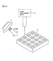
- a system 1 for inspecting a micro structure according to a first embodiment of the present invention is provided with a tester (inspection device) 5 and a substrate 10 where a number of chips TP of micro structure having microscopic moveable parts are formed.
- a three-axis acceleration sensor which has multiple axes is cited and described as an example of a micro structure that is to be tested.
- Tester 5 is provided with a speaker 2 for outputting sound wave which is compression wave, an input/output interface 15 for transferring input/output data between the outside and the inside of the tester, a control unit 20 for controlling the entirety of tester 5, probe needles 4 which are used to make contact with the test object, a speaker controlling unit 30 for controlling speaker 2 in response to an instruction from control unit 20, a microphone 3 for detecting sound from the outside, and a signal adjusting unit 35 for converting the sound wave that has been detected by microphone 3 into a voltage signal, and furthermore, for amplifying the voltage signal which is then outputted to control unit 20.
- the three-axis acceleration sensor of a micro structure which is the test object is described, before describing the inspection method according to the present embodiment.
- a number of pads PD are placed around the periphery of a chip TP that is formed on a substrate 10 as viewed from the top of a three-axis acceleration sensor device.
- metal wires for transmitting an electrical signal to a pad or for transmitting an electrical signal from a pad are provided.
- four proof masses AR that form a four-leafed clover shape are placed in the center portion.
- this three-axis acceleration sensor is of a piezoresistive element type, and a piezoresistive element which is a detection element is provided as resistance of diffused region.
- This piezoresistive element type acceleration sensor can be made using an inexpensive IC process, and the sensitivity is not lowered, even in the case where the resistor element that is a detection element is formed so as to be small, and therefore, this acceleration sensor is advantageous for miniaturization and reduction in cost.
- Proof masses AR at the center have structures that are supported by four beams BM in a concrete configuration.
- Beams BM are formed so as to be perpendicular to each other in the two axial directions X and Y, where four piezoresistive elements are provided for each axis.
- Four piezoresistive elements for detection in the direction of the Z axis are provided on the side of the piezoresistive elements for detection in the direction of the X axis.
- the form of the upper surface of proof masses AR is in four-leafed clover form, and proof masses AR are linked to beams BM in the center portion. It becomes possible to implement a highly sensitive acceleration sensor which is compact, even though the size of proof masses AR is increased and at the same time the length of the beams is increased, by adopting this four-leafed clover type structure.
- the sensing mechanism of the three-axis acceleration sensor of this piezoresistive element type provides a mechanism where beams BM are deformed when the proof masses receive acceleration (force of inertia) and the acceleration is detected due to a change in the resistance values of the piezoresistive elements which have been formed on the surface of the beams.
- this output of the sensor is set to be taken out in the configuration as the output of the below described Wheatstone's bridge, where three axes arc independently associated.
- a piezoresistive element has property where the resistance value thereof changes due to a warp that has been caused (piezoresistive element effect), in a manner where the resistance value increases in the case of a warp caused by stretching and the resistance value decreases in the case of a warp caused by compression.
- piezoresistive elements for detection in the direction of the X axis Rx1 to Rx4 piezoresistive elements for detection in the direction of the Y axis Ry1 to Ry4
- piezoresistive elements for detection in the direction of the Z axis Rz1 to Rz4 are shown as examples.
- Fig. 5A is a circuit configuration diagram of a Wheatstone's bridge along the X (Y) axis.
- the output voltages of the X axis and the Y axis are assumed to be Vxout and Vyout, respectively.
- Fig. 5B is a circuit configuration diagram of a Wheatstone's bridge along the Z axis.
- the output voltage of the Z axis is assumed to be Vzout.
- the resistance values of the four piezoresistive elements along each axis change due to a warp that has been caused, and on the basis of this change, the circuit that is formed as a Wheatstone's bridge by each piezoresistive element along, for example, the X axis and the Y axis, detects the acceleration component along each axis of the output as an independent, separate output voltage.
- the above-described metal wires and the like, as shown in Fig. 2 are linked so that a circuit as described above is formed, and an output voltage for each axis is detected from a predetermined pad in the configuration.
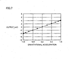
- this three-axis acceleration sensor can detect the DC component of acceleration, and therefore, it is possible to use this three-axis acceleration sensor as an inclination angle sensor for detecting acceleration in the gravity, that is, as an angular rate sensor.
- a sensor is rotated around the X, Y and Z axes so that the respective bridge outputs of the X, Y and Z axes are respectively measured by a digital voltage meter.
- a low voltage power supply of +5 V is utilized as the power supply for the sensor.
- values from which the offsets of the respective axial outputs have been arithmetically decreased are plotted as the respective measurement points shown in Figs. 6A to 6C.
- the input/output relationship shown in Fig. 7 is gained by calculating the gravity acceleration components which respectively relate to the X, Y and Z axes form the cosines of the inclination angles of Figs. 6A to 6C so as to find the relationship between the gravity acceleration (input) and the output of the sensor, and by evaluating the linearity of this input/output, That is, the relationship between the acceleration and the output voltage is approximately linear.
- the three-axis acceleration sensor('s proof mass AR) When the three-axis acceleration sensor('s proof mass AR) is vibrated for example along the Z axis and the three-axis acceleration sensor rotates around the X or Y axis (or other than the Z axis), Coriolis force acts on proof mass AR. As Coriolis force's direction and magnitude can be detected, the three-axis acceleration sensor can be used as an angular rate sensor.
- a method employing a three-axis acceleration sensor to measure angular speed is more specifically described for example by Nobumitsu Taniguchi, et al. "Micromachined 5-axis Motion Sensor with Electrostatic Drive and Capacitive Detection", Technical Digest of the 18th Sensor Symposium, 2001, pp. 377-380.
- the frequency properties of the outputs of sensors along the X, Y and Z axes, respectively, are indicated as flat frequency properties up to the vicinity of 200 Hz along all of the three axes, in an example where there are resonations at 602 Hz along the X axis, at 600 Hz along the Y axis and at 883 Hz along the Z axis.
- a method for inspecting a micro structure provides a system for outputting sound wave which is compression wave to a three-axis acceleration sensor that is a micro structure, and thereby, detecting the movement of the moveable part of the micro structure on the basis of these sound wave, so as to evaluate the property thereof.
- Fig. 9 first, inspection (testing) of a micro structure is started (step S0).
- probe needles 4 are made to make contact with pads PD of chip to be tested TP (step S1).
- probe needles 4 are made to make contact with predetermined pads PD in order to detect the output voltage of the Wheatstone's bridge circuit described in Fig. 5.
- Fig. 1 shows a configuration where a pair of probe needles 4 is used, it is possible to provide a configuration where a number of pairs of probe needles are used.
- Employing a plurality of pairs of probe needles allows detecting, in parallel, signals output from a plurality of outputs of a single chip TP and/or a plurality of chips TPs.
- test sound wave that is outputted from speaker 2 are set (step S2a). Specifically speaking, control unit 20 receives an input of input data from the outside via input/output interface 15. Then, control unit 20 controls speaker controlling unit 30 and instructs speaker controlling unit 30 so that test sound wave having a desired frequency and a desired sound pressure are outputted from speaker 2 on the basis of the input data. Next, test sound wave is outputted from speaker 2 to chip to be tested TP (step S2b).
- microphone 3 is used to detect test sound wave which is supplied to chip to be tested TP from speaker 2 (step S3).
- the test sound wave that has been detected by microphone 3 are converted to a voltage signal which is then amplified in signal adjusting unit 35, and the resulting signal is outputted to control unit 20.
- control unit 20 analyzes and determines the voltage signal that is inputted from signal adjusting unit 35, and determines whether or not desired test sound wave has reached the control unit (step S4).
- control unit 20 determines desired test sound wave in step S4
- the procedure goes to the next step S5, where the property value of the chip to be tested is measured.
- the property value is measured in measurement part 25 on the basis of an electrical signal that is transmitted via probe needles 4 (step S5).
- the moveable part of a micro structure of the chip to be tested moves due to the arrival of test sound wave which is compression wave outputted form speaker 2, that is, air vibrations.
- a change in the resistance value of the three-axis acceleration sensor which is the micro structure that changes on the basis of this movement is measured on the basis of the output voltage that is supplied via probe needles 4.
- control unit 20 instructs speaker controlling unit 30 to correct the test sound wave.
- Speaker controlling unit 30 microscopically adjusts the frequency and/or the sound pressure so as to gain desired test sound wave in response to the instruction from control unit 20, and thus, controls the system so that the desired test sound wave is outputted from speaker 2.
- a system where test sound wave is detected and corrected to desired test sound wave is described in the present embodiment, it is possible to provide a configuration where a part for correcting test sound wave and a system for correcting test sound wave are not particularly provided in the cases desired test sound wave-reaches the micro structure of the chip to be tested in advance.
- processing up to steps S2a to S4 is implemented in advance before the start of testing, and a corrected control value for outputting desired test sound wave is stored in speaker controlling unit 30. Then, at the time of testing of the actual micro structure, speaker controlling unit 30 controls the input to speaker 2 with this recorded control value, and thereby, it becomes possible to omit the above-described processing in steps S3 and S4 at the time of testing.
- control unit 20 determines whether or not the measured property value, that is, measured data, is in an allowable range (step S6). In the case where it is determined to be in the allowable range in step S6, it is passed (step S7), and the outputting and storing of data are implemented (step S8). Then, the procedure goes to step S9.
- a desired output voltage is gained in response to the sound pressure of test sound wave which is outputted from speaker 2, or more concretely, whether or not the resistance value of the three-axis acceleration sensor changes in linear form in response to a change in the sound pressure of the test sound wave which is outputted from speaker, that is, whether or not the linear relationship described in Fig. 7 is gained, and thereby, whether or not the chip has appropriate property, can be determined.
- data is stored in a storage unit, such as a memory, not shown, that is provided inside tester 5 on the basis of an instruction from control unit 20.
- step S10 the inspection (testing) of a micro structure is completed.
- step S9 the procedure returns to the initial step S1, and the above-described inspection is again implemented.
- control unit 20 determines that the measured property value, that is, the measured data, is not in the allowable range in step S6, it is failed (step S 11) and re-inspection is carried out (step S12).
- a chip that is determined to be outside of the allowable range can be removed through re-inspection.
- chips that are determined to be outside of the allowable range can be divided into a number of groups. That is, it is considered that many chips exist which are chips that cannot pass strict test conditions but do not cause any problems even if they are shipped after modification and correction. Accordingly, it is possible to select chips by grouping the chips through re-inspection and the like, and to ship some of the chips on the basis of the selection result.
- a configuration is described as an example where a change in the resistance value of a piezoresistive element that is provided in a three-axis acceleration sensor is detected and determined by means of an output voltage in response to the movement of the three-axis acceleration sensor, it is also possible to provide a configuration where a change in the impedance value, such as that of a capacitor element or a reactance element, without being particularly limited to a resistor element, or a change in the voltage, the current, the frequency, the phase difference, the delay time and the position on the basis of a change in the impedance value is detected and determined.
- Fig. 10 shows the output voltage that is outputted from a three-axis acceleration sensor in the case where test sound wave of 1 Pa (Pascal) is supplied as sound pressure, and the frequency thereof is changed.
- the vertical axis indicates the output voltage (mV) of the three-axis acceleration sensor, and the horizontal axis indicates the frequency (Hz) of the test sound wave.
- Fig. 10 shows two regions A and B. Specifically speaking, Fig. 10 shows resonant frequency region A, and non resonant frequency region B.
- the frequency where the output voltage is the maximum corresponds to the resonant frequency.
- the frequency that corresponds to this output is approximately 600 Hz. That is, it almost coincides with the frequency property of the three-axis acceleration sensor along the X axis.
- the resonant frequency from the property of the output voltage that are gained when, for example, the frequency of test sound wave is changed while making the sound pressure constant, and it becomes possible to determine whether or not this specified resonant frequency is a desired resonant frequency after the comparison between this specified frequency and the desired resonant frequency.
- the X axis is illustrated in the present embodiment, it is possible to gain the frequency properties along the X axis and the Z axis in the same manner, and therefore, the properties of the acceleration sensor along the three respective axes can be evaluated simultaneously.
- test sound wave using, for example, the frequency region of region B, that is, the non resonant frequency region, so as to perform detection and inspection of the sensitivity and the offset of a three-axis acceleration sensor from the output result.
- test sound wave spreads uniformly, and therefore, it is also possible to perform the same inspection on a number of chips in parallel.
- it is relatively easy to control the frequency and sound pressure of test sound wave and therefore, the configuration of the unit can be made to be simple and easy, in comparison with the configuration of the unit for controlling the amount of flow of air.
- the property of a micro structure can be inspected with high precision from the movement of the moveable part of the micro structure in the configuration of an inspection method and an inspection device according to the first embodiment, which is a simple system for controlling sound wave which is compression wave.
- a driver unit that reads the program that has been stored in a recording medium is provided in tester 5, and control unit 20 receives the program via the driver unit and stores the program in a memory within control unit 20, and thereby, it is possible to carry out the above-described inspection method.
- this program it is possible for this program to be downloaded from a server so that control unit 20 can carry out the above-described inspection method.
- the inspection system described in Japanese Laid-Open Patent Publication No. 05-034371 has a configuration where the property of an acceleration sensor device having one axis are inspected by blowing air against the device, and the properties of a multi-axial acceleration sensor cannot be inspected without changing the direction (angle) from which air is blown against the device.
- inspection system I 1 according to the modification of the first embodiment of the present invention is different from that of the first embodiment in the point where tester 5 is replaced with tester 6.
- Tester 6 is different from tester 5 in the point where microphone 3 and signal adjusting unit 35 are not present in tester 6.
- the other parts are the same, and the descriptions thereof are not repeated.
- step S0 inspection (testing) of a micro structure is started as described above (step S0), and probe needles 4 are made to make contact with pads PD of chip to be tested TP (step S1).
- step S2a test sound wave which is to be outputted from speaker 2 are set (step S2a), and then, test sound wave is outputted from speaker 2 to chip to be tested TP (step S2b).
- the property value of the chip to be tested is measured. Specifically speaking, the property value is measured by measurement part 25 on the basis of an electrical signal that is transmitted via prove needles 4, as described above (step S20).
- control unit 20 determines whether or not the property value that has been measured by measurement part 25, that is, measured data, coincides with a desired property value, that is, measured data (step S21).
- control unit 20 instructs speaker controlling unit 30 to correct test sound wave so that a desired property value is gained through chip to be tested TP as a result of measurement by measurement part 25.
- speaker controlling unit 30 microscopically adjusts the frequency and/or sound pressure of the test sound wave so that a desired property value can be gained, and thus, controls the system so that test sound wave is outputted from speaker 2 and a desired property is gained.
- control unit 20 acquires data on the sound pressure, frequency, voltage and the like of the test sound wave for gaining a desired property value when control unit 20 instructs speaker controlling unit 30 to output such test sound wave from speaker 2.
- control unit 20 determines whether or not the acquired data is in an allowable range (step S6).
- step S6 in the case where it is determined that the data is in the allowable range, it is passed (step S7), while in the case where it is determined that the data is not in the allowable range, it is failed (step S11).
- step S6 in the case where it is determined that the data is in the allowable range, it is passed (step S7), while in the case where it is determined that the data is not in the allowable range, it is failed (step S11).
- a method for inspecting a micro structure according to the modification of the first embodiment of the present invention is a method for determining whether or not a chip to be tested has passed or failed, by comparing the level of the sound pressure or the like of predetermined test sound wave that has been set in advance and outputted from speaker 2 so that a predetermined property value detected from a passed chip, that is, a good product, can be gained, with the level of the sound pressure or the like of test sound wave that has been outputted so that this predetermined property value can be gained through the chip to be tested.
- tester 6 where microphone 3 and signal adjusting part 35 described in the first embodiment are not provided, can evaluate the property of a chip to be tested, and the cost of the tester can further be reduced by decreasing the number of parts.
- an inspection system 1# according to the second embodiment of the present invention is different from inspection system 1 in the point where tester 5 has been replaced with tester 5#.
- Other parts are the same as in inspection system 1 that is described in Fig. 1, and therefore, the detailed descriptions thereof are not repeated.
- Tester 5# according to the second embodiment of the present invention is different from tester 5 in the point where tester 5# further includes a noise removal controlling unit 40, a speaker 2# and a microphone 3#. Other parts are the same, and the detailed descriptions thereof are not repeated.
- the method for inspecting a micro structure according to the second embodiment is different from the inspection method that is described in Fig. 9 in the point where steps S13 to S 16 have further been added between steps S1 and S2a.
- noise sound wave is detected using microphone 3# (step S13).
- microphone 3# detects noise sound wave that emanates from noise source NS and outputs the result thereof to noise removal controlling unit 40.
- noise removal controlling unit 40 instructs speaker 2# to set anti-noise sound wave for canceling the noise sound wave that emanates from noise source NS (step S 14), and to output the anti noise sound wave to chip to be tested TP from the speaker (step S 15).
- anti-noise sound wave having the same frequency and the same sound pressure as those of noise sound wave and in phases opposite to the phases of the noise sound wave are outputted. As a result of this, as shown in Fig.
- control unit 20 determines whether or not noise sound wave has been removed on the basis of the output result from signal adjusting unit 35 via microphone 3 (step S16). In the case where it is determined that the noise sound wave have been removed, the procedure goes to the above-described next step S2a, and the following processes are the same as those described in Fig. 9, and the detailed descriptions thereof are not repeated.
- control unit 20 instructs noise removal controlling unit 40 to allow speaker controlling unit 30 to correct anti noise sound wave.
- noise removal controlling unit 40 microscopically adjusts the frequency and/or sound pressure and/or phases of the anti noise sound wave so that they become desired anti noise sound wave, and controls the system so that anti noise sound wave is outputted from speaker 2#.
- noise can be removed or cancelled as a pre-process, before the output of test sound wave, and thus, inspection with high precision can be performed under conditions where there is no noise at the time of testing.
- the present example it is also possible for the present example to have a configuration where a corrector and system are not specifically provided in advance in the case where desired test sound wave reaches the micro structure of a chip to be tested.
- processes up to steps S2a to S4 are carried out in advance before the start of testing, and a corrected control value for outputting desired test sound wave is stored in speaker controlling unit 30.
- speaker controlling unit 30 controls an input to speaker 2 with this recorded control value at the time of actual testing of a micro structure, and thereby, it is possible to omit the above-described processes in steps S3 and S4 at the time of testing.
- an inspection system 1#a according to a first modification of the second embodiment of the present invention is different from inspection system 1# that is described in Fig. 13 in the point where tester 5# has been replaced with a tester 5#a.
- tester 5#a is different from tester 5# in the point where speaker 2# does not exist, and noise removal controlling unit 40 has been replaced with a noise removal controlling unit 40# and a speaker controlling unit 30#.
- Other parts are the same as in the inspection systems that arc described in Figs. 1 and 13, and therefore, the detailed descriptions thereof are not repeated.
- Noise removal controlling unit 40# of tester 5#a instructs speaker controlling unit 30# to output the above-described anti-noise sound wave for removing noise sound wave that has been detected by microphone 3# from speaker 2.
- speaker controlling unit 30# instructs the system to output anti noise sound wave together with test sound wave from speaker 2.
- Anti noise sound wave and test sound wave are generated using speaker 2 as in the configuration according to the first modification of the second embodiment of the present invention, and thereby, the number of parts can further be reduced, so as to reduce cost.
- speaker controlling unit 30 outputs test sound wave which is sine wave having a single frequency from a speaker
- the present invention is not limited to this, but rather, it is possible to synthesize sine wave signal having a number of different frequencies using, for example, an adder, not shown, and output the resulting signal from a speaker.
- responses to a number of frequencies can be detected at one time, and therefore, inspection of frequency response property as described in Fig. 10 can be efficiently and effectively performed.
- a frequency band to be inspected is divided into a high band and a low band and signals of single sine waves selected from the high and low bands, respectively, are composited together and thus output from the speaker and a signal responding thereto is divided by a band filter, responses to two frequencies can simultaneously be detected.
- test sound wave that is outputted from a speaker are not limited to a sine wave signal or a synthesized signal of sine wave signal, but rather, test sound wave having an arbitrary waveform, such as white noise, may be outputted using a function generator (generator of an arbitrary waveform), not shown.
- a micro structure exhibits a response that is dominated by the resonance of the moveable part, because white noise, for example, includes approximately the same amount of components of all frequencies, and the resonant frequency and vibration property of the micro structure can be easily inspected by detecting such a response.
- Fig. 32 is a graph representing a result of detecting responses of the three axes simultaneously as a white noise of a frequency range is output as a test sound wave.
- the test sound wave by the white noise is output and the three axes' output signals for a measurement time are each subjected to Fourier transform and plotted versus frequency.
- Fig. 32 shows a first measurement result.
- peaks representing resonant frequencies for the x, y and z axes respectively.
- resonant frequencies around 1220-1240 Hz are indicated
- a resonant frequency around 1980 Hz is indicated.
- the input is a pseudo white noise, however resonant frequency and average output level can be evaluated.
- a result of subjecting the test sound wave for the measurement time to Fourier transform is preferably used to normalize a frequency component of an output signal for each frequency. Furthermore such measurement may be done more than once and an average for each frequency may be provided. Furthermore If a moving average is provided for each appropriate frequency section and plotted in a graph, such crests and troughs as seen in Fig. 32 can be leveled to help to visually apprehend the property.
- the present method is different from the inspection method that is described in Fig. 14 in the point where steps S13 to S 16 are replaced with steps S30 to S33.
- step S1 noise sound wave is detected using the property value of a chip to be tested that is to be detected via probe needles (step S30).
- the probe needles are made to make contact with pads of the chip to be tested, and thereby, the moveable part is moved by noise sound wave or vibrations which are emitted from noise sound source NS, so that a predetermined property value is detected from the chip to be tested via the probe needles.
- Measurement part 25 outputs this result to control unit 20.
- Control unit 20 instructs noise removal controlling unit 40 to remove noise on the basis of the predetermined property value that has been measured by measurement part 25,
- noise removal controlling unit 40 sets anti-noise sound wave for canceling noise sound wave that is emitted from noise source NS in the speaker (step S31), and instructs chip to be tested TP to output anti-noise sound wave from the speaker (step S32).
- anti-noise sound wave which has the same frequency and the same sound pressure as the noise sound wave and which is in phases opposite to those of the noise sound wave is outputted.
- anti-noise sound wave "fantinoise” which is in phases exactly opposite to those of noise sound wave “fnoise” which is emitted from, for example, noise source NS, as shown in Fig. 16, are outputted from speaker 2#, and thereby, are synthesized, and noise sound wave “fnoise” is cancelled so as to be almost non-existent when the synthesized sound wave reaches chip TP of the micro structure.
- control unit 20 determines whether or not the noise sound wave has been removed (step S33). Specifically speaking, it is determined whether or not a predetermined property value from the chip to be tested that is detected by measurement part 25 via the probe needles has become 0, that is, whether or not a predetermined property value has not been detected.
- step S2a In the case where a predetermined property value has not been detected by measurement part 25 via the probe needles, that is, it is determined that noise sound wave has been removed, the procedure goes to the above-described next step S2a, and the following process is the same as that described in Fig. 9, and the detailed descriptions thereof are not repeated. Alternatively, it is also possible for the procedure to go to step S2a, where the following testing process is carried out in accordance with a system as described in Fig. 12.
- step S33 the procedure returns to step S31 again, in the case where it is determined in step S33 that the noise sound wave has not been removed, That is, anti-noise sound wave is reset.
- control unit 20 instructs noise removal controlling unit 40 to allow speaker controlling unit 30 to correct the anti-noise sound wave.
- noise removal controlling unit 40 microscopically adjusts the frequency and/or sound pressure and/or phases so that desired anti-noise sound wave can be gained, that is, a predetermined property value that is measured by measurement part 25 via the probe needles becomes 0 and controls the system so that the anti-noise sound wave is outputted from the speaker.
- noise can be removed, that is, canceled, as a pre-process before outputting test sound wave, and inspection with high precision can be performed in the state where there is no noise at the time of testing.
- microphone 3# can be eliminated from the above-described testers 5# and 5#a, that is, the number of parts can be reduced, and the cost of the testers can be reduced.
- the inspection method according to the second modification of the second embodiment of the present invention is a method for testing by outputting test sound wave after the property value of the chip to be tested that is detected via probe needles has been adjusted to 0 as a pre-process before outputting the test sound wave. That is, the present inspection method is a method for testing in the state where the effects of noise have been completely removed on the basis of the actual measurement result, and therefore, inspection with high precision can be performed in comparison with the methods which are described in the second embodiment and the first modification.
- a three-axis acceleration sensor is described as an example of a micro structure, there are various types of MEMS technologies, as described above, and the micro structure that is the object of the present technology is not limited to a multi-axial acceleration sensor.
- the present technology can be utilized for performance inspection of the operation property and mechanical property of an actuator and a microscopic mechanical part, as illustrated in the below.
- Fig. 18A is a diagram for illustrating a case where a switch is stationary.
- an MEMS switch (hereinafter simply referred to as switch) is formed of a substrate 50, a cantilever 51, a control electrode 52, a cantilever joining part 53 and a joining electrode 54. In the state where no control signal is inputted, the switch does not operate.
- Fig. 18B is a diagram for illustrating a case where the switch operates.
- cantilever 51 is attracted to the control electrode 52 side.
- cantilever joining part 53 makes contact with joining electrode 54.
- the switch becomes of the ON state.
- a control signal in pulse form is supplied to control electrode 52, for example, cantilever joining part 53 moves upward and downward, repeating the joined state/non-joined state to joining electrode 54.
- This switch is microscopic, and is utilized as a switch for changing the frequency at high speed.
- Fig. 19A is a diagram for illustrating signal wires and electrodes.
- a signal wire 72 into which a signal is inputted and a signal wire 73 from which a signal is outputted are shown.
- a trench is provided between the signal wires in the vicinity of the center portion, where an electrically insulated state is shown.
- electrodes 70 and 71 are provided on the two sides of the signal wires in the configuration.
- Fig. 19B is a diagram for illustrating a case where the membrane structure is used as a switch.
- a membrane is placed above signal wires 72 and 73, Thin film beams form flexible springs. These support membrane 74.
- a driving voltage is applied to electrodes 70 and 71, and thereby, membrane 74 warps and is pulled down by electrostatic attraction, in a manner where the membrane makes contact with the signal wires which are provided beneath the membrane, As a result of this, the trench between the signal wires is filled in, providing the conductive state (ON). That is, the state where signal wires 72 and 73 are conductive is gained, so that an inputted signal is outputted. Meanwhile, in the case where the membrane and the signal wires do not make contact with each other, the state of non-conductivity (OFF) is gained.
- this membrane structure is not limited to a switch, but may also be a sensor part, such as a temperature sensor.
- the present technology makes it possible to perform performance inspection on a variety of mechanical parts, such as electron/ion transmitting thin films, using the property of a thin film or the illumination window of an electron beam illuminator, without moving the thin film portion, which is a moveable part of the membrane structure, at the time of utilization of the product.
- a membrane structure is used for the illumination window of an electron beam illuminator.
- electron beam EB is emitted into the air from a vacuum tube 81 through an illumination window 80, and an enlarged cross section of a portion of illumination window 80 shows that a membrane structure is adopted in the thin film.
- Fig. 20 illustrates only one membrane structure where the membrane is formed of a single material, in some cases, the membrane may be formed of a number of materials so as to have a multi-layered film structure, or may be formed as an illumination window where a number of membrane structures are arranged in array form. In accordance with the technology of the present invention, it is possible to inspect the existence of damage or a crack in the film, or the film quality, even in a mechanical part that has a moveable part, as described above.
- Fig. 21A is a diagram for illustrating a case where an inkjet printer head is stationary.
- the inkjet printer head is formed of a nozzle 60, a piezoelectric actuator 61, a cover member 62, a support member 64 for supporting piezoelectric actuator 61, a control electrode 63a, a control electrode 63b that is joined to piezoelectric actuator 61, a substrate 65 and a switch 66.
- switch 66 is turned off, the inkjet printer head does not operate.
- an ink is filled in between cover member 62 and piezoelectric actuator 61.
- Fig. 21B is a diagram for illustrating a case where the inkjet printer head operates.
- Fig. 21C is a diagram for illustrating a case where the switch is turned off after Fig. 21B.
- piezoelectric actuator 61 that has been warped returns to its original state. At this time, a force of repulsion is gained, and thereby, the ink that fills the inside is jetted out from nozzle 60.
- This inkjet printer head operates as described above, and thereby, can be utilized as a microscopic and high-speed printer head.
- piezoelectric actuator 61 deforms and electrostatic capacitance between control electrodes 63a and 63b varies. By detecting this variation the printer head can be inspected.
- Fig. 33A is a plan view of a pressure sensor and Fig. 33B is a cross section taken along a line A-A of Fig. 33A.
- a silicon substrate Si has a center provided with a diaphragm D substantially in a square and small in thickness.
- Diaphragm D has four sides having intermediate points with piezoelectric resistances R1, R2, R3, R4, respectively.
- a stress is caused in piezoelectric resistances R1-R4.
- the stress varies piezoelectric resistances R1-R4 in electrical resistance, and by detecting the variation the difference between pressures exerted to the opposite sides of diaphragm D can be measured.
- the present method also allows the pressure sensor's operation to be confirmed such that the pressure sensor is formed on a substrate (for example a wafer). Exerting pressure to confirm operation entails causing a difference in pressure at opposite surfaces of a wafer, and it is difficult to perform inspection with the pressure sensor formed on the wafer.
- the acceleration sensor (or angular rate sensor) MEMS switch, membrane structure, inkjet printer head, pressure sensor and other similar movable part different in property are combined together to form a micro structure, e.g., if the acceleration sensor and the pressure sensor are combined together to form a single micro structure, such plurality of movable parts properties can simultaneously be inspected.
- a substrate is often provided thereon with a plurality of micro structure, and the present method allows a plurality of micro structure on a substrate to be inspected simultaneously. Simultaneously inspecting a plurality of movable parts or those different in property or a plurality of micro structure allows an MEMS production process to be performed in a reduced period of time. Furthermore a substrate with a micro structure thereon can be inspected, and if a defective product is found it can be excluded from a subsequent packaging process and/or the like.
- the systems as shown in the first and second embodiments are described as systems for inspecting the property of a micro structure by detecting an electrical signal that is outputted from the micro structure primarily by making probe needles make contact with pads of a chip having the micro structure.
- a system is specifically described where it is possible to inspect the property of a micro structure without directly using an electrical signal that is outputted from the micro structure. Specifically speaking, the system is described using the illumination window of an electron beam illuminator having a membrane structure.
- measurement part 25# in accordance with the third embodiment of the present invention includes a measurement unit 46 and a measurement jig 45.
- measurement unit 46 and measurement jig 45 are electrically coupled to each other via a terminal TP.
- Measurement unit 46 detects an electrostatic capacitance between an electrode ED and the object of measurement at the time of testing.
- Measurement jig 45 includes a number of pads PD# which are provided in the periphery of the outer region, and a number of electrodes ED which are provided in the inner region thereof
- one electrode ED is provided so as to correspond to one pad PD# from among the number of pads PD#, and these are electrically coupled to each other.
- Fig. 22 shows a case where one pad PD# and terminal TP are electrically coupled to each other as an example.
- the illumination window 80 of an electron beam illuminator having a membrane structure that is a micro structure is mounted on this measurement jig 45 as an example.
- a tester of the third embodiment has a configuration where probe needles 4 have been removed and measurement part 25 which is the tester described in Fig. 1 is replaced with measurement part 25#, and other parts, such as the control unit and the speaker, have the same configuration, and therefore, the detailed descriptions thereof are not repeated.
- measurement jig 45 and illumination window 80 of the electron beam illuminator that has been mounted on measurement jig 45 are described in detail.
- electrode ED is provided on the surface of measurement jig 45. Also, spacers 47 are provided so as to secure a predetermined space L between electrode ED and illumination window 80. In addition, electrode ED and external pad PD# are electrically coupled to each other, as described above.
- testing Inspection (testing) of a micro structure is started as described above (step S0). At this time, illumination window 80 of the electron beam illuminator having the micro structure that is the object of inspection is mounted on measurement jig 45. Next, test sound wave which is outputted from speaker 2 are set (step S2a), and then, test sound wave is outputted to illumination window 80 from speaker 2 (step S2b).
- the property value of the inspection chip is measured.
- the electrostatic capacitance value that changes on the basis of the displacement of the moveable part that moves due to compression wave that is outputted from speaker 2 is measured by measurement unit 46 of measurement part 25# (step S5a).
- control unit 20 determines whether or not the property value that has been measured by measurement part 25#, that is, the measured data, has a desired property value, that is, is in an allowable range (step S6).
- the method for inspecting a micro structure according to the third embodiment of the present invention is not a method for inspecting the property of a micro structure on the basis of an electrical signal or the like that is directly gained from the micro structure due to the movement of the moveable part as described in Fig. 9, but rather, a method for inspecting property of the micro structure on the basis of a property value that is indirectly measured from the movement of the micro structure.
- measurement jig 45 and illumination window 80 of the electron beam illuminator that is mounted on measurement jig 45 are described in detail.
- illumination window 80 having the membrane structure that is shown in Fig. 25 is different from illumination window 80 shown in Fig. 23 in the point where illumination window 80 having the membrane structure that is shown in Fig. 23 is placed so as to face downward, while illumination window 80 having the membrane structure that is shown in fig 25 is placed so as to face upward.
- a spacer 48 and a sub electrode EDa are provided on top of electrode ED, and electrode ED and sub electrode EDa are electrically coupled to each other through a contact hole that goes through spacer 48.
- the distance between the electrode, that is, sub electrode EDa, and the membrane structure is set at L.
- the three-axis acceleration sensors of the above-described micro structure can also be inspected in accordance with the same system.
- the resonant frequency at the time when probe needles are made to make contact with pads of a three-axis acceleration sensor is described.
- the greater the needle pressure of the probe needles which are made to make contact with pads is, the lower the resonant frequency tends to become. Accordingly, inspection can be easily performed without using probe needles and without changing the predetermined resonant frequency, by detecting and inspecting the electrostatic capacitance value that changes on the basis of the displacement of the moveable part that moves due to compression wave which is outputted from the above-described speaker.
- a chip TP of a three-axis acceleration sensor is mounted on a measurement part 25#a.
- Measurement part 25#a includes capacitance detection circuits CS 1 and CS2, electrode EDb and measurement unit 46#.
- the tester of the present example has a configuration where probe needles 4 are removed and measurement part 25 of the tester that is described in fig 1 is replaced with measurement part 25#a in the same manner as described above, while other parts, such as the control unit and the speaker, have the same configuration, and therefore, the detailed descriptions thereof are not repeated.
- Two electrodes EDb are provided beneath proof masses AR having a three-axis acceleration sensor, and are electrically coupled to capacitance detection circuits CS1 and CS2, respectively.
- capacitance detection circuits CS 1 and CS2 are connected to measurement unit 46# so as to output the detected capacitance value.
- Measurement unit 46# measures the changing electrostatic capacitance value.
- Fig. 27B is a circuit configuration diagram for illustrating capacitance detection in measurement part 25#a.
- the initial values of electrostatic capacitances Cd 1 and Cd2 between proof mass AR and electrode EDb are respectively detected by capacitance detection circuits CS2 and CS2. Then, the detection result are outputted to measurement unit 46#.
- proof mass AR which is the moveable part, displaces due to compression wave from speaker 2.
- Fig. 29A shows a case where electrodes EDb are provided so as to correspond to proof masses AR, respectively, as described above, but it is also possible to perform inspection in accordance with the same system as that described above, by providing one electrode ED# corresponding to proof masses AR, as shown in Fig. 29B.
- Fig. 29C it is also possible to perform inspection by providing electrodes ED#a, which are larger than the bottom areas of proof masses AR, in the present example, where the detection areas are greater than electrodes EDb that are shown in Fig. 29A.
- the system shown in Fig. 24 of the present specification is the same system as that in the case where step S 1 that is described in Fig. 9 is removed from the first embodiment. That is, this is a system for evaluating property of a micro structure depending on whether or not desired property data has been detected in accordance with test sound wave which is supplied from speaker 2. In the same manner, it is also possible to evaluate the property in accordance with a system which is described in Fig. 12 of the modification of the first embodiment, Fig. 14 or Fig. 17 of the second embodiment or its modification, from which step S 1 is removed.
- test sound wave for gaining desired property data so as to evaluate the property of a micro structure depending on whether or not data such as the sound pressure of the gained test sound wave is within an allowable range, or by outputting anti-noise sound wave even in the case where noise sound wave or the like is generated.
- a tester by eliminating probe needles 4 in Figs. 1, 11, 13 and 16, as described above, and by changing measurement part 25 to the above-described measurement part 25# or 25#a.
- sound wave which is compression wave so as to evaluate the property of the moveable part of a micro structure from the movement thereof with the naked eye.
- sound wave which is compression wave to a micro structure and to detect displacement in the movement of the moveable part of the micro structure using a so-called laser displacement meter, a displacement sensor or a proximity sensor so as to evaluate the property of the micro structure, by determining whether or not the detected amount of displacement is a desired amount of displacement by means of a determinator or the like.
- property of illumination window 80 of an electron beam illuminator can be tested on the basis of whether or not a desired displacement has been detected.
- the third embodiment also allows a plurality of movable parts or those different in property or a plurality of micro structure to be simultaneously inspected. Furthermore, a test sound wave in the form of white noise or that of a prescribed frequency range can be applied to a micro structure to eliminate the necessity of scanning the test sound wave's frequency in inspecting the micro structure's property.
Landscapes
- Physics & Mathematics (AREA)
- General Physics & Mathematics (AREA)
- Engineering & Computer Science (AREA)
- Biochemistry (AREA)
- Pathology (AREA)
- Immunology (AREA)
- General Health & Medical Sciences (AREA)
- Health & Medical Sciences (AREA)
- Life Sciences & Earth Sciences (AREA)
- Chemical & Material Sciences (AREA)
- Analytical Chemistry (AREA)
- Remote Sensing (AREA)
- Radar, Positioning & Navigation (AREA)
- Signal Processing (AREA)
- Acoustics & Sound (AREA)
- Manufacturing & Machinery (AREA)
- Mathematical Physics (AREA)
- Spectroscopy & Molecular Physics (AREA)
- Microelectronics & Electronic Packaging (AREA)
- Measurement Of Mechanical Vibrations Or Ultrasonic Waves (AREA)
- Micromachines (AREA)
- Investigating Or Analyzing Materials By The Use Of Ultrasonic Waves (AREA)
- Pressure Sensors (AREA)
Applications Claiming Priority (6)
| Application Number | Priority Date | Filing Date | Title |
|---|---|---|---|
| JP2004174423 | 2004-06-11 | ||
| JP2004174423 | 2004-06-11 | ||
| JP2005064876 | 2005-03-09 | ||
| JP2005064876 | 2005-03-09 | ||
| JP2005160701 | 2005-05-31 | ||
| JP2005160701A JP4387987B2 (ja) | 2004-06-11 | 2005-05-31 | 微小構造体の検査装置、微小構造体の検査方法および微小構造体の検査プログラム |
Publications (2)
| Publication Number | Publication Date |
|---|---|
| EP1605258A2 true EP1605258A2 (fr) | 2005-12-14 |
| EP1605258A3 EP1605258A3 (fr) | 2007-05-30 |
Family
ID=35005669
Family Applications (1)
| Application Number | Title | Priority Date | Filing Date |
|---|---|---|---|
| EP20050012547 Withdrawn EP1605258A3 (fr) | 2004-06-11 | 2005-06-10 | Dispositif et procédé pour inspection sonique de microstructures |
Country Status (6)
| Country | Link |
|---|---|
| US (1) | US7383732B2 (fr) |
| EP (1) | EP1605258A3 (fr) |
| JP (1) | JP4387987B2 (fr) |
| KR (1) | KR20060046415A (fr) |
| SG (1) | SG118367A1 (fr) |
| TW (1) | TW200609508A (fr) |
Cited By (2)
| Publication number | Priority date | Publication date | Assignee | Title |
|---|---|---|---|---|
| EP3147258A1 (fr) * | 2015-09-22 | 2017-03-29 | AT & S Austria Technologie & Systemtechnik Aktiengesellschaft | Panneau de connexion pour composants électroniques |
| CN111198282A (zh) * | 2018-11-16 | 2020-05-26 | 西门子工业软件公司 | 用于校准扬声器的集成体积加速度传感器的方法和系统 |
Families Citing this family (15)
| Publication number | Priority date | Publication date | Assignee | Title |
|---|---|---|---|---|
| US7814777B2 (en) * | 2005-01-03 | 2010-10-19 | Koninklijke Philips Electronics N.V. | Background acoustic signal suppression in photoacoustic detector |
| WO2006093232A1 (fr) * | 2005-03-03 | 2006-09-08 | Tokyo Electron Limited | Dispositif, procede et programme d'inspection de micro-structure |
| JP4573794B2 (ja) * | 2005-03-31 | 2010-11-04 | 東京エレクトロン株式会社 | プローブカードおよび微小構造体の検査装置 |
| JP2007040896A (ja) * | 2005-08-04 | 2007-02-15 | Tokyo Electron Ltd | 微小構造体の検査装置、検査方法および検査プログラム |
| EP2135068A4 (fr) * | 2007-03-10 | 2013-05-15 | Ruv Systems B V | Procédé et appareil pour le contrôle de qualité en ligne de tranches |
| US9933394B2 (en) | 2007-03-10 | 2018-04-03 | Sergei Ostapenko | Method and apparatus for detecting cracks and delamination in composite materials |
| WO2009069670A1 (fr) * | 2007-11-26 | 2009-06-04 | Tokyo Electron Limited | Dispositif d'inspection de microstructure et procédé d'inspection de microstructure |
| JP5470724B2 (ja) * | 2008-03-13 | 2014-04-16 | トヨタ自動車株式会社 | 振動試験装置 |
| US8368289B2 (en) * | 2008-04-10 | 2013-02-05 | SpectraQuest, Inc. | Nondestructive testing apparatus and method |
| US8076921B1 (en) * | 2008-09-18 | 2011-12-13 | The United States Of America As Represented By The Secretary Of The Navy | Self-regulating power supply for micro electronic mechanical systems thermal actuators |
| JP5676315B2 (ja) * | 2011-03-07 | 2015-02-25 | 大阪瓦斯株式会社 | 流体識別装置及び流体識別方法 |
| JP5929138B2 (ja) * | 2011-12-06 | 2016-06-01 | セイコーエプソン株式会社 | 圧電モーターおよびロボット |
| JP5996343B2 (ja) * | 2012-09-14 | 2016-09-21 | 東芝メディカルシステムズ株式会社 | 超音波診断装置 |
| EP2747075A3 (fr) * | 2012-12-21 | 2016-06-22 | Intermec IP Corp. | Reduction active de bruit en boucle fermée, tel que pour imprimante thermique |
| CN113055889B (zh) * | 2021-02-01 | 2022-06-14 | 浙江大学 | 一种基于惯性测量单元共振特征的手机牧场检测与标定方法 |
Citations (2)
| Publication number | Priority date | Publication date | Assignee | Title |
|---|---|---|---|---|
| JPH06313785A (ja) * | 1993-04-28 | 1994-11-08 | Hioki Ee Corp | 振動による実装部品の半田付け不良検出方法並びに加振装置及び加振、測定プローブユニット |
| FR2847384A1 (fr) * | 2002-11-01 | 2004-05-21 | Suss Microtec Test Sys Gmbh | Procede et dispositif pour tester des substrats sensibles aux mouvements |
Family Cites Families (20)
| Publication number | Priority date | Publication date | Assignee | Title |
|---|---|---|---|---|
| DE3706765C3 (de) * | 1987-03-03 | 1995-11-09 | Telefunken Microelectron | Aufprallsensor für ein Fahrzeug, mit einer Prüfschaltung |
| JPS63241459A (ja) | 1987-03-30 | 1988-10-06 | Fujitsu General Ltd | 半田付不良検査方法 |
| DE3736294A1 (de) | 1987-10-27 | 1989-05-11 | Messerschmitt Boelkow Blohm | Einrichtung zur funktionskontrolle von beschleunigungssensoren |
| US4816125A (en) | 1987-11-25 | 1989-03-28 | The Regents Of The University Of California | IC processed piezoelectric microphone |
| JPH0267956A (ja) | 1988-09-02 | 1990-03-07 | Oki Electric Ind Co Ltd | 電子部品のリード・オープン不良検出装置 |
| FR2666887A1 (fr) * | 1990-09-17 | 1992-03-20 | Asulab Sa | Capteur de mesure d'une grandeur physique. |
| US5481184A (en) * | 1991-12-31 | 1996-01-02 | Sarcos Group | Movement actuator/sensor systems |
| US6295870B1 (en) * | 1991-02-08 | 2001-10-02 | Alliedsignal Inc. | Triaxial angular rate and acceleration sensor |
| JPH0534371A (ja) | 1991-07-31 | 1993-02-09 | Tokai Rika Co Ltd | 半導体加速度センサの感度測定装置 |
| JPH05203485A (ja) | 1992-01-28 | 1993-08-10 | Koichi Nakano | 共振周波数自動検出方法及びその装置 |
| JPH09196682A (ja) * | 1996-01-19 | 1997-07-31 | Matsushita Electric Ind Co Ltd | 角速度センサと加速度センサ |
| JPH112643A (ja) | 1997-06-12 | 1999-01-06 | Denso Corp | 加速度センサの周波数特性検査装置 |
| US6507187B1 (en) * | 1999-08-24 | 2003-01-14 | The United States Of America As Represented By The Administrator Of The National Aeronautics And Space Administration | Ultra-sensitive magnetoresistive displacement sensing device |
| JP3440037B2 (ja) | 1999-09-16 | 2003-08-25 | 三洋電機株式会社 | 半導体装置、半導体エレクトレットコンデンサマイクロホンおよび半導体エレクトレットコンデンサマイクロホンの製造方法。 |
| JP3902134B2 (ja) * | 2001-01-22 | 2007-04-04 | エランテック デバイシーズ コーポレイション | 応力センサ |
| US6595058B2 (en) * | 2001-06-19 | 2003-07-22 | Computed Ultrasound Global Inc. | Method and apparatus for determining dynamic response of microstructure by using pulsed broad bandwidth ultrasonic transducer as BAW hammer |
| WO2003096444A2 (fr) * | 2002-05-13 | 2003-11-20 | University Of Florida | Reseau et systeme mems resonants comprenant un processeur d'energie pouvant etre modifie de façon dynamique |
| US6836336B2 (en) * | 2002-10-08 | 2004-12-28 | Bechtel Bwxt Idaho, Llc | Inspection system calibration methods |
| US7463364B2 (en) * | 2003-07-31 | 2008-12-09 | Ler Technologies, Inc. | Electro-optic sensor |
| JP4573794B2 (ja) * | 2005-03-31 | 2010-11-04 | 東京エレクトロン株式会社 | プローブカードおよび微小構造体の検査装置 |
-
2005
- 2005-05-31 JP JP2005160701A patent/JP4387987B2/ja not_active Expired - Fee Related
- 2005-06-08 TW TW094118936A patent/TW200609508A/zh not_active IP Right Cessation
- 2005-06-10 KR KR20050049878A patent/KR20060046415A/ko active IP Right Grant
- 2005-06-10 US US11/149,176 patent/US7383732B2/en not_active Expired - Fee Related
- 2005-06-10 SG SG200503730A patent/SG118367A1/en unknown
- 2005-06-10 EP EP20050012547 patent/EP1605258A3/fr not_active Withdrawn
Patent Citations (2)
| Publication number | Priority date | Publication date | Assignee | Title |
|---|---|---|---|---|
| JPH06313785A (ja) * | 1993-04-28 | 1994-11-08 | Hioki Ee Corp | 振動による実装部品の半田付け不良検出方法並びに加振装置及び加振、測定プローブユニット |
| FR2847384A1 (fr) * | 2002-11-01 | 2004-05-21 | Suss Microtec Test Sys Gmbh | Procede et dispositif pour tester des substrats sensibles aux mouvements |
Cited By (3)
| Publication number | Priority date | Publication date | Assignee | Title |
|---|---|---|---|---|
| EP3147258A1 (fr) * | 2015-09-22 | 2017-03-29 | AT & S Austria Technologie & Systemtechnik Aktiengesellschaft | Panneau de connexion pour composants électroniques |
| WO2017050696A1 (fr) | 2015-09-22 | 2017-03-30 | At&S Austria Technologie & Systemtechnik Aktiengesellschaft | Panneau de connexion pour composants électroniques |
| CN111198282A (zh) * | 2018-11-16 | 2020-05-26 | 西门子工业软件公司 | 用于校准扬声器的集成体积加速度传感器的方法和系统 |
Also Published As
| Publication number | Publication date |
|---|---|
| TWI370899B (fr) | 2012-08-21 |
| JP4387987B2 (ja) | 2009-12-24 |
| EP1605258A3 (fr) | 2007-05-30 |
| US20050279170A1 (en) | 2005-12-22 |
| TW200609508A (en) | 2006-03-16 |
| US7383732B2 (en) | 2008-06-10 |
| JP2006313137A (ja) | 2006-11-16 |
| KR20060046415A (ko) | 2006-05-17 |
| SG118367A1 (en) | 2006-01-27 |
Similar Documents
| Publication | Publication Date | Title |
|---|---|---|
| US7383732B2 (en) | Device for inspecting micro structure, method for inspecting micro structure and program for inspecting micro structure | |
| TWI289204B (en) | Minute structure inspection device, minute structure inspection method, and minute structure inspection program | |
| JP4573794B2 (ja) | プローブカードおよび微小構造体の検査装置 | |
| KR101011491B1 (ko) | 미소 구조체의 검사 장치, 미소 구조체의 검사 방법 및 기판 유지 장치 | |
| US20090128171A1 (en) | Microstructure Probe Card, and Microstructure Inspecting Device, Method, and Computer Program | |
| US20080302185A1 (en) | Microstructure Inspecting Apparatus and Microstructure Inspecting Method | |
| US20090039908A1 (en) | Microstructure inspecting apparatus and microstructure inspecting method | |
| TWI300844B (fr) | ||
| US20080223136A1 (en) | Minute structure inspection device, inspection method, and inspection program | |
| JP4856426B2 (ja) | 微小構造体の検査装置、及び微小構造体の検査方法 | |
| JP4822846B2 (ja) | 微小構造体の検査装置、微小構造体の検査方法および微小構造体の検査プログラム | |
| JP2006284553A (ja) | 微小構造体の検査装置、微小構造体の検査方法および微小構造体の検査プログラム | |
| US20100225342A1 (en) | Probe card and microstructure inspecting apparatus | |
| WO2010121846A1 (fr) | Système et procédé d'inspection pour tester des structures microfabriquées |
Legal Events
| Date | Code | Title | Description |
|---|---|---|---|
| PUAI | Public reference made under article 153(3) epc to a published international application that has entered the european phase |
Free format text: ORIGINAL CODE: 0009012 |
|
| AK | Designated contracting states |
Kind code of ref document: A2 Designated state(s): AT BE BG CH CY CZ DE DK EE ES FI FR GB GR HU IE IS IT LI LT LU MC NL PL PT RO SE SI SK TR |
|
| AX | Request for extension of the european patent |
Extension state: AL BA HR LV MK YU |
|
| RIN1 | Information on inventor provided before grant (corrected) |
Inventor name: YAKABE, MASAMIC/O TOKYO ELECTRON AT LTD. Inventor name: IKEUCHI, NAOKIC/O TOKYO ELECTRON AT LTD. Inventor name: MATUSMOTO, TOSHIYUKIC/O TOKYO ELECTRON AT LTD. Inventor name: OKUMURA, KATSUYAC/O OCTEC INC. |
|
| RIN1 | Information on inventor provided before grant (corrected) |
Inventor name: YAKABE, MASAMI Inventor name: IKEUCHI, NAOKI Inventor name: MATUSMOTO, TOSHIYUKI Inventor name: OKUMURA, KATSUYAC/O OCTEC INC. |
|
| PUAL | Search report despatched |
Free format text: ORIGINAL CODE: 0009013 |
|
| AK | Designated contracting states |
Kind code of ref document: A3 Designated state(s): AT BE BG CH CY CZ DE DK EE ES FI FR GB GR HU IE IS IT LI LT LU MC NL PL PT RO SE SI SK TR |
|
| AX | Request for extension of the european patent |
Extension state: AL BA HR LV MK YU |
|
| 17P | Request for examination filed |
Effective date: 20070611 |
|
| 17Q | First examination report despatched |
Effective date: 20070816 |
|
| AKX | Designation fees paid |
Designated state(s): AT BE BG CH CY CZ DE DK EE ES FI FR GB GR HU IE IS IT LI LT LU MC NL PL PT RO SE SI SK TR |
|
| STAA | Information on the status of an ep patent application or granted ep patent |
Free format text: STATUS: THE APPLICATION IS DEEMED TO BE WITHDRAWN |
|
| 18D | Application deemed to be withdrawn |
Effective date: 20100605 |