EP1605238A1 - Elektronischer Heizkostenverteiler - Google Patents
Elektronischer Heizkostenverteiler Download PDFInfo
- Publication number
- EP1605238A1 EP1605238A1 EP05009634A EP05009634A EP1605238A1 EP 1605238 A1 EP1605238 A1 EP 1605238A1 EP 05009634 A EP05009634 A EP 05009634A EP 05009634 A EP05009634 A EP 05009634A EP 1605238 A1 EP1605238 A1 EP 1605238A1
- Authority
- EP
- European Patent Office
- Prior art keywords
- temperature sensor
- circuit board
- heat cost
- cost allocator
- room air
- Prior art date
- Legal status (The legal status is an assumption and is not a legal conclusion. Google has not performed a legal analysis and makes no representation as to the accuracy of the status listed.)
- Granted
Links
- 238000010438 heat treatment Methods 0.000 claims abstract description 3
- 239000004020 conductor Substances 0.000 claims description 15
- 229920002379 silicone rubber Polymers 0.000 claims description 2
- 239000004945 silicone rubber Substances 0.000 claims description 2
- 238000011156 evaluation Methods 0.000 description 6
- 238000000034 method Methods 0.000 description 6
- 238000004519 manufacturing process Methods 0.000 description 5
- 230000000694 effects Effects 0.000 description 3
- 238000005259 measurement Methods 0.000 description 3
- 125000006850 spacer group Chemical group 0.000 description 3
- 238000005452 bending Methods 0.000 description 2
- 230000008878 coupling Effects 0.000 description 2
- 238000010168 coupling process Methods 0.000 description 2
- 238000005859 coupling reaction Methods 0.000 description 2
- 239000004033 plastic Substances 0.000 description 2
- 230000005855 radiation Effects 0.000 description 2
- 229910000679 solder Inorganic materials 0.000 description 2
- OPFJDXRVMFKJJO-ZHHKINOHSA-N N-{[3-(2-benzamido-4-methyl-1,3-thiazol-5-yl)-pyrazol-5-yl]carbonyl}-G-dR-G-dD-dD-dD-NH2 Chemical compound S1C(C=2NN=C(C=2)C(=O)NCC(=O)N[C@H](CCCN=C(N)N)C(=O)NCC(=O)N[C@H](CC(O)=O)C(=O)N[C@H](CC(O)=O)C(=O)N[C@H](CC(O)=O)C(N)=O)=C(C)N=C1NC(=O)C1=CC=CC=C1 OPFJDXRVMFKJJO-ZHHKINOHSA-N 0.000 description 1
- 239000004793 Polystyrene Substances 0.000 description 1
- 239000000853 adhesive Substances 0.000 description 1
- 230000001070 adhesive effect Effects 0.000 description 1
- 230000009286 beneficial effect Effects 0.000 description 1
- 230000005540 biological transmission Effects 0.000 description 1
- 229940126086 compound 21 Drugs 0.000 description 1
- 230000000994 depressogenic effect Effects 0.000 description 1
- 230000008020 evaporation Effects 0.000 description 1
- 238000001704 evaporation Methods 0.000 description 1
- 239000004973 liquid crystal related substance Substances 0.000 description 1
- 229920002223 polystyrene Polymers 0.000 description 1
- 238000003825 pressing Methods 0.000 description 1
- 230000001681 protective effect Effects 0.000 description 1
- 238000005476 soldering Methods 0.000 description 1
Images



Classifications
-
- H—ELECTRICITY
- H05—ELECTRIC TECHNIQUES NOT OTHERWISE PROVIDED FOR
- H05K—PRINTED CIRCUITS; CASINGS OR CONSTRUCTIONAL DETAILS OF ELECTRIC APPARATUS; MANUFACTURE OF ASSEMBLAGES OF ELECTRICAL COMPONENTS
- H05K1/00—Printed circuits
- H05K1/02—Details
- H05K1/0201—Thermal arrangements, e.g. for cooling, heating or preventing overheating
-
- G—PHYSICS
- G01—MEASURING; TESTING
- G01K—MEASURING TEMPERATURE; MEASURING QUANTITY OF HEAT; THERMALLY-SENSITIVE ELEMENTS NOT OTHERWISE PROVIDED FOR
- G01K17/00—Measuring quantity of heat
- G01K17/06—Measuring quantity of heat conveyed by flowing media, e.g. in heating systems e.g. the quantity of heat in a transporting medium, delivered to or consumed in an expenditure device
-
- G—PHYSICS
- G01—MEASURING; TESTING
- G01K—MEASURING TEMPERATURE; MEASURING QUANTITY OF HEAT; THERMALLY-SENSITIVE ELEMENTS NOT OTHERWISE PROVIDED FOR
- G01K17/00—Measuring quantity of heat
- G01K17/06—Measuring quantity of heat conveyed by flowing media, e.g. in heating systems e.g. the quantity of heat in a transporting medium, delivered to or consumed in an expenditure device
- G01K17/08—Measuring quantity of heat conveyed by flowing media, e.g. in heating systems e.g. the quantity of heat in a transporting medium, delivered to or consumed in an expenditure device based upon measurement of temperature difference or of a temperature
-
- H—ELECTRICITY
- H05—ELECTRIC TECHNIQUES NOT OTHERWISE PROVIDED FOR
- H05K—PRINTED CIRCUITS; CASINGS OR CONSTRUCTIONAL DETAILS OF ELECTRIC APPARATUS; MANUFACTURE OF ASSEMBLAGES OF ELECTRICAL COMPONENTS
- H05K1/00—Printed circuits
- H05K1/02—Details
- H05K1/0201—Thermal arrangements, e.g. for cooling, heating or preventing overheating
- H05K1/0203—Cooling of mounted components
- H05K1/0204—Cooling of mounted components using means for thermal conduction connection in the thickness direction of the substrate
- H05K1/0206—Cooling of mounted components using means for thermal conduction connection in the thickness direction of the substrate by printed thermal vias
-
- H—ELECTRICITY
- H05—ELECTRIC TECHNIQUES NOT OTHERWISE PROVIDED FOR
- H05K—PRINTED CIRCUITS; CASINGS OR CONSTRUCTIONAL DETAILS OF ELECTRIC APPARATUS; MANUFACTURE OF ASSEMBLAGES OF ELECTRICAL COMPONENTS
- H05K1/00—Printed circuits
- H05K1/18—Printed circuits structurally associated with non-printed electric components
-
- H—ELECTRICITY
- H05—ELECTRIC TECHNIQUES NOT OTHERWISE PROVIDED FOR
- H05K—PRINTED CIRCUITS; CASINGS OR CONSTRUCTIONAL DETAILS OF ELECTRIC APPARATUS; MANUFACTURE OF ASSEMBLAGES OF ELECTRICAL COMPONENTS
- H05K2201/00—Indexing scheme relating to printed circuits covered by H05K1/00
- H05K2201/01—Dielectrics
- H05K2201/0104—Properties and characteristics in general
- H05K2201/0133—Elastomeric or compliant polymer
-
- H—ELECTRICITY
- H05—ELECTRIC TECHNIQUES NOT OTHERWISE PROVIDED FOR
- H05K—PRINTED CIRCUITS; CASINGS OR CONSTRUCTIONAL DETAILS OF ELECTRIC APPARATUS; MANUFACTURE OF ASSEMBLAGES OF ELECTRICAL COMPONENTS
- H05K2201/00—Indexing scheme relating to printed circuits covered by H05K1/00
- H05K2201/06—Thermal details
- H05K2201/062—Means for thermal insulation, e.g. for protection of parts
-
- H—ELECTRICITY
- H05—ELECTRIC TECHNIQUES NOT OTHERWISE PROVIDED FOR
- H05K—PRINTED CIRCUITS; CASINGS OR CONSTRUCTIONAL DETAILS OF ELECTRIC APPARATUS; MANUFACTURE OF ASSEMBLAGES OF ELECTRICAL COMPONENTS
- H05K2201/00—Indexing scheme relating to printed circuits covered by H05K1/00
- H05K2201/09—Shape and layout
- H05K2201/09009—Substrate related
- H05K2201/09063—Holes or slots in insulating substrate not used for electrical connections
-
- H—ELECTRICITY
- H05—ELECTRIC TECHNIQUES NOT OTHERWISE PROVIDED FOR
- H05K—PRINTED CIRCUITS; CASINGS OR CONSTRUCTIONAL DETAILS OF ELECTRIC APPARATUS; MANUFACTURE OF ASSEMBLAGES OF ELECTRICAL COMPONENTS
- H05K2201/00—Indexing scheme relating to printed circuits covered by H05K1/00
- H05K2201/09—Shape and layout
- H05K2201/09209—Shape and layout details of conductors
- H05K2201/09218—Conductive traces
- H05K2201/09263—Meander
-
- H—ELECTRICITY
- H05—ELECTRIC TECHNIQUES NOT OTHERWISE PROVIDED FOR
- H05K—PRINTED CIRCUITS; CASINGS OR CONSTRUCTIONAL DETAILS OF ELECTRIC APPARATUS; MANUFACTURE OF ASSEMBLAGES OF ELECTRICAL COMPONENTS
- H05K2201/00—Indexing scheme relating to printed circuits covered by H05K1/00
- H05K2201/09—Shape and layout
- H05K2201/09209—Shape and layout details of conductors
- H05K2201/09654—Shape and layout details of conductors covering at least two types of conductors provided for in H05K2201/09218 - H05K2201/095
- H05K2201/09781—Dummy conductors, i.e. not used for normal transport of current; Dummy electrodes of components
-
- H—ELECTRICITY
- H05—ELECTRIC TECHNIQUES NOT OTHERWISE PROVIDED FOR
- H05K—PRINTED CIRCUITS; CASINGS OR CONSTRUCTIONAL DETAILS OF ELECTRIC APPARATUS; MANUFACTURE OF ASSEMBLAGES OF ELECTRICAL COMPONENTS
- H05K2201/00—Indexing scheme relating to printed circuits covered by H05K1/00
- H05K2201/10—Details of components or other objects attached to or integrated in a printed circuit board
- H05K2201/10007—Types of components
- H05K2201/10151—Sensor
Definitions
- the invention relates to an electronic heat cost allocator with one in one Housing arranged printed circuit board according to the preamble of the claim 1.
- a radiator serving electronic heat cost allocators are in contrast to a Evaporation heat cost allocator usually used two temperature sensors.
- a sensor is used to determine the surface temperature of a Radiator and the other sensor to determine the room temperature.
- the heat cost allocator has as part of the housing usually a made of a thermally conductive material back part, which on Radiator directly attached and thermally conductive with a radiator surface connected is.
- a back part On the back part is a e.g. made of plastic housing front part put on, in conjunction with the back part a closed Housing of the electronic heat cost allocator represents.
- a printed circuit board Inside the case a printed circuit board is arranged, which in addition to other components or components the temperature sensors for measuring the radiator temperature on the one hand and the room air temperature on the other.
- the temperature sensor is mechanically stressed and on the other hand loses the spring pushing the circuit board against the back part, in the course the time at spring force, so that the thermally conductive contact between the Temperature sensor and the back part is not granted permanently.
- the back part of the known electrical heat cost allocator from a thermally conductive material detects the pressed to the back part Temperature sensor not only the temperature in the immediate area of the Temperature sensor, but also the thermally conductive back surrounding Temperature.
- the pressed to the front of the housing captures Room air temperature sensor due to the low thermal conductivity of the usual made of a plastic front part only the temperature in the immediate vicinity of the room air temperature sensor.
- the invention is based on the object, an electronic heat cost allocator specify with the avoiding the disadvantages mentioned a reliable Measurement of both radiator and room air temperature without mechanical Load of the temperature sensors is enabled. Also for a fast and efficient manufacturing process on the one hand and to reduce the Size of the area of the circuit board used for the heat cost allocator on the other SMD components (automatic components) and others Automatenbe Georgiabare components can be used automatically placed on the circuit board, fixed and with running on the circuit board traces can be electrically connected.
- At least one of the two temperature sensors is a thermally conductive and elastically deformable element assigned. With this is the corresponding one Temperature sensor thermally conductively connected via an electrically conductive element.
- This electrically conductive element can by a on the circuit board running conductor, through a via from one side of the circuit board to the other side of the circuit board or through a combination of be formed both.
- the electronic heat cost allocator has a arranged in a housing Printed circuit board with a first plate side (component side) and a second Plate side up. On the first plate side, preferably both the radiator temperature sensor as well as a room temperature sensor and a first the radiator temperature sensor associated thermally conductive and elastic deformable element arranged. The radiator temperature sensor and the Room air temperature sensor are at opposite ends of the plate of the first Plate side provided.
- a second thermally conductive and elastically deformable Element is in a preferred embodiment of the invention on a housing inside arranged and with the room air temperature sensor via one of the first on the second side plate leading, electrically and / or thermally conductive connection connected thermally conductive.
- the circuit board of the heat cost allocator according to the invention has a component side on, which faces the radiator side. Consequently, also the On the PCB arranged radiator temperature sensor and on the circuit board arranged room air temperature sensor facing the radiator side.
- To measure a room air side and a radiator side temperature is It's beneficial, not just the temperature in the immediate vicinity of each To detect temperature sensor, but the respective Temparatursensor to assign a thermally conductive body of greater extent, as a result thermally conductive connection with the temperature sensor which thermally conductive Body surrounding temperature is reliably detected.
- the radiator temperature sensor is therefore a (first) thermally conductive and elastically deformable Assigned element such that this one hand, the radiator temperature sensor and on the other hand, a radiator side housing inner wall of the housing of Heat cost allocator contacted to determine the radiator surface temperature.
- the circuit board is advantageously only one side with automatzusbeschbaren Provided components. As a result, a machine loading process only needs one be performed once, so that in a row by a second Automatenbe conductedungsrea problems are reliably avoided.
- the room air temperature sensor on (second) associated with thermally conductive and elastically deformable element.
- the second element is on the radiator side facing away from the inside of the housing arranged and contacted both the inside of the housing and the inside of the housing facing second side of the plate.
- the room air temperature sensor thermally over one from the first to the second plate side and / or electrically conductive connection with the second, thermally conductive and connected elastically deformable element.
- the thermal or electrically conductive Connection is preferably carried out as a via, which the Room air temperature sensor and the second element via a on the second side of the plate running, large-scale track contacted.
- the circuit board in the housing in the housing longitudinal direction arranged obliquely.
- This arrangement is for the opposite PCB ends provided temperature sensors to the effect advantageous that the radiator temperature sensor as close to a radiator side housing inside is arranged.
- the room air temperature sensor is also as close to a room air side housing inside arranged.
- Another advantage for the arrangement of both temperature sensors opposite plate ends of the circuit board is the thermal decoupling the temperature sensors.
- the temperature sensors are over As long as possible conductor tracks electrically conductive with a likewise on the circuit board arranged evaluation unit connected. These tracks are on the circuit board preferably running meandering running.
- the circuit board has at least one Interruption in the form of preferably a through opening of the one Plate side of the PCB on the opposite side of the plate to the thermal Decoupling of the temperature sensors.
- the circuit board provided with a plurality of through holes, which are rectangular, circular or square. Multiple through holes can in the vicinity of the temperature sensors at the opposite ends of the plate be provided the circuit board.
- the room air temperature sensor particularly reliable thermally against the radiator to isolate and acting on the room air temperature sensor heat radiation to keep the radiator as low as possible, is the thermally insulating Element compared to the dimensions of the room air temperature sensor over a large area is executed.
- the first and the second plate side can be reversed, so that the first The side facing away from the radiator side and facing the room air side is.
- the thermally conductive one associated with the heating temperature sensor is then and elastically deformable element via a via of the component side to the mounting side opposite plate side the circuit board thermally conductively connected to the radiator temperature sensor.
- the electronic heat cost allocator 1 comprises a housing 2 with a hood-like, housing-side housing front side 3a and one of these radiator side occlusive back 3b.
- the electronic Heat cost allocator 1 a circuit board or board 4 arranged thereon Components and / or components in the form of electronic components for determining an amount of heat emitted by a radiator.
- this data further comprises an LC display 9 (liquid crystal display), an infrared interface 8 and a radio-frequency antenna 13.
- the LCD display 9 can the data determined by the heat cost allocator 1 are read directly.
- the data determined by the heat cost allocator 1 over the infrared interface 8 are also read out electrically on site.
- the infrared interface 8 also serves for the wireless control of the heat cost allocator 1, for example, for the configuration or programming of the electronic Heat cost allocator 1.
- the radio frequency antenna arranged on the inside of the housing 13 is for centralized data transmission and control of one or more provided electronic heat cost allocator 1 in a building.
- the electronic heat cost allocator 1 comprises two temperature sensors, namely a radiator temperature sensor 6 and a room air temperature sensor 5. Both temperature sensors 5, 6 are on the same side 17 of the plate Printed circuit board 4 is arranged.
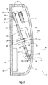
- Fig. 2 shows schematically the arrangement of the temperature sensors 5, 6 on the circuit board 4.
- the circuit board 4 is inclined arranged in the longitudinal direction of the housing 2, so that the radiator temperature sensor 6 in the immediate vicinity of the radiator side 3b and the back Room air temperature sensor 5 facing away in the immediate vicinity of the back 3b Housing inside of the housing 2 is located.
- the machine assembly takes place the circuit board 4 with automatic components or components only on a single plate side 17 of the circuit board 4. This the production position of the circuit board 4 can be significantly accelerated.
- FIGS. 4a and 4b The plate sides 17 and 18 of the circuit board 4 with the plate side 17 as Component side.
- an evaluation unit 24 and others unspecified automatic components or components.
- the plate side 18 is provided with non-automatenbe Anlagenbaren devices or Components provided after the automatic loading process on the Printed circuit board 4 are processed.
- non-automatable components or components count on the one hand on the component side 17 opposite plate side 18 of the circuit board 4 arranged and over a spacer 12 fixed battery 7 to power the electronic Heat cost allocator 1 and on the other hand, the infrared interface 8, the High-frequency antenna 13 and the LC display 9.
- the on the plate side 18 of the Printed circuit board 4 arranged battery 7 is thermally via a spacer 12 isolated from the temperature sensors 5, 6.
- electronic heat cost allocator 1 is the component side 17 with both the indoor 5 as also facing the radiator temperature sensor 6 of the back 3b.
- a radiator surface temperature of a radiator is the radiator temperature sensor 6 thermally conductive with a radiator surface of not shown radiator via the directly attached to the radiator surface Rear 3b connected.
- a thermally conductive and elastically deformable member 11 is pressed on the back side 3b and connected to the back 3b thermally conductive.
- the thermally conductive and elastically deformable element 11 is manufactured as an automatable component and also arranged on the plate side 17 of the circuit board 4.
- the housing front side 3a with the circuit board 4 located there on the in Radiator attached back 3b mounted so adjusts the thermally conductive and elastically deformable element 11 to the shape and orientation of the back 3b elastically deforming.
- the thermally conductive and elastic deformable element 11 is a pressing of the radiator temperature sensor 6 to the back 3b superfluous, because the radiator temperature sensor 6 is with the thermally conductive and elastically deformable element 11 via at least a conductor 22 thermally conductively connected.
- radiator temperature sensor 6 and the thermally conductive and elastically deformable element 11 To optimize the thermal Coupling between the radiator temperature sensor 6 and the thermally conductive and elastically deformable element 11 are the radiator temperature sensor 6 and the thermally conductive and elastically deformable element 14 immediately arranged side by side on the circuit board 4 and over the comparatively short conductor 22 thermally connected. Furthermore, the association office between the conductive line 22 and the thermal coupling element 11 executed over a large area.
- the room air temperature sensor 5 For improved measurement of a room air temperature is the room air temperature sensor 5 in contrast to the radiator temperature sensor 6, located in the immediate Near the rear 3b is located, at the greatest possible distance from the radiator facing back 3b arranged in the housing 2.
- the temperature sensors 5, 6 supporting circuit board 4 with a printed circuit board end 20 in the immediate Near the back of 3b and with the other PCB end 19 in the immediate Near a rear side 3b remote from the inside of the housing housing 2 is arranged.
- the circuit board 4 is inclined in the housing longitudinal direction arranged.
- the electronic heat cost allocator includes 1 on the one hand, a thermally conductive connection 21 from the plate side 17 to the Plate side 17 opposite and the back 3b facing away from the plate side 18 of the circuit board 4 and on the other hand, a thermally conductive element, the between the plate side 18 and the rear side 3b facing away from the inside of the housing is arranged.
- the room air temperature sensor 5 is connected to the thermally conductive Element 10 via the from the plate side 17 to the plate side 18 reaching conductive Connection 21 thermally coupled.
- This is the thermally conductive compound 21 executed as a via or as a wire, for example.
- the thermally conductive element 10 is also formed elastically deformable and Accordingly, when inserting the circuit board 4 in the front side 3 a of the Housing 2 to the shape and orientation of the circuit board 4 elastically deforming at.
- the thermally conductive and elastically deformable element 10 is - as well as the thermally conductive and elastically deformable element 11 - for example of silicone rubber. Via the thermally conductive connection 21 between the room air temperature sensor 5 and the thermally conductive and elastically deformable element 10, the room air temperature sensor 5 detects not only the temperature in its immediate environment, but also the temperature in the immediate Surrounding the thermally conductive and elastically deformable element 10, which in Compared to the room air temperature sensor 5 a body with much larger Represents dimensions.
- the arrangement of the temperature sensors 5, 6 at the opposite ends of the plate 19 and 20 of the circuit board 4 is also to the effect of advantage that the two temperature sensors 5 and 6 thermally by their spatial distance are decoupled from each other. Furthermore, the printed circuit board 4 at least an interruption 23, the thermal decoupling of both temperature sensors further improved.
- the interruption represents a in the circuit board. 4 existing passage opening 23 is for thermal decoupling of both Temperature sensors 5, 6, the circuit board 4 preferably has a plurality of through holes 23 on. These are located in the immediate vicinity of the radiator temperature sensor 6 and the room air temperature sensor 5 and surround the respective Temperature sensor 5 or 6 at least partially.
- the electronic heat cost allocator 1 for the thermal decoupling of the room air temperature sensor. 5 and the thermally conductive back 3b at least one thermally insulating Element 14, which between the back 3b and the room air temperature sensor 5 is arranged.
- the thermally insulating element 14 represents, for example a prepared from polystyrene insulating part. Preferably, that is Insulating part 14 in comparison to the room air temperature sensor 5 over a large area form, so that not only the room air temperature sensor 5, but also in its immediate vicinity on the circuit board 4 extending traces against direct heat radiation and convection of the heated by the radiator Air is shielded.
- the electronic heat cost allocator 1 comprises a device for detecting mechanical manipulation of the electronic heat cost allocator 1.
- the device comprises a facing away from the back 3 Front inside 2 of the housing arranged spring element 16, an electric conductive contact disk 15, two arranged on the circuit board electrically conductive, but from each other electrically isolated contact surfaces 26, which as comparatively formed over a large area conductor tracks, and an on the plate side 18 of the printed circuit board 4 arranged, the contact disk 15 carrying, rectangular and flexurally elastic element 25.
- the flexurally elastic Element 25 is attached to a longitudinal end 27 on the printed circuit board 4. At the end 27 opposite the longitudinal end 28 of the flexurally elastic Elements 25, the contact disc 15 is attached.
- the contact disk 15 is arranged such that these on the circuit board 4 arranged contact surfaces 26 with depressed flexurally elastic element 25 closes shortly.
- the electrically connected to the contact surfaces 26 Evaluation unit 24 registers a voltage applied to the contact surfaces 26 Short circuit or idle and thus closing or interrupting the contact between the contact disc 15 and the two contact surfaces 26th by removing the printed circuit board 4 from the front side 3a of the housing 2 or by inserting the circuit board 4 in the front side 2 of the housing.
- the mechanical manipulation of the electrical heat cost allocator 1 is so electrically detected by closing or opening a contact. Not just the Disassembly of the circuit board 4 from the front side 3a of the housing 2, but also opening the housing 2 of the electronic heat cost allocator 1 by Removal of the circuit board 4 supporting front side 3a of the directly on To detect radiator attached back 3b, has the flexurally elastic element 25 to a lever arm 29, which upon closing of the housing 2 by putting on of the front part 3a on the back side 3b is pressed against this.
- the rear side 3b presses the flexurally elastic element 25 via the lever arm 29 away from the circuit board 4. This will make the contact between the two contact surfaces 26 and the contact disc 5 interrupted.
- the evaluation unit 24 of the electronic heat cost allocator 1 detects on the one hand the removal of the circuit board 4 supporting housing front side 3a of the Back 3b, by the contact between the two contact surfaces 26 closed becomes. On the other hand, the disassembly of the circuit board 4 from the front 3a of the housing 2 detected by the contact between the two contact surfaces 26 is opened.
- the electronic heat cost allocator 1 is the requirements of a mass product fair, because they are produced efficiently and inexpensively can. Furthermore, the electronic heat cost allocator 1 is a durable and high quality product, especially for the function of an electronic Heat cost allocator 1 important electronic components mechanical not be charged.
Landscapes
- Engineering & Computer Science (AREA)
- Chemical & Material Sciences (AREA)
- Combustion & Propulsion (AREA)
- Physics & Mathematics (AREA)
- General Physics & Mathematics (AREA)
- Microelectronics & Electronic Packaging (AREA)
- Cooling Or The Like Of Electrical Apparatus (AREA)
- Fire-Detection Mechanisms (AREA)
- Investigating Or Analyzing Materials Using Thermal Means (AREA)
- Combinations Of Printed Boards (AREA)
- Central Heating Systems (AREA)
Abstract
Description
- Fig. 1
- in perspektivischer Darstellung einen elektronischen Heizkostenverteilers mit teilweise geschnittenem Gehäuse,
- Fig. 2
- den elektronischen Heizkostenverteiler nach Fig. 1 in einem Längsschnitt entlang der Linie II-II in Fig. 3,
- Fig. 3
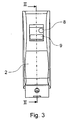
- eine Draufsicht auf die von einer Heizkörperseite abgewandte Gehäuseaußenseite eines elektronischen Heizkostenverteilers,
- Fig. 4a
- in Draufsicht eine erste Plattenseite einer im Gehäuse des Heizkostenverteilers angeordneten Leiterplatte, und
- Fig. 4b
- in Draufsicht die zweite Plattenseite der.Leiterplatte.
- 1
- Elektronischer Heizkostenverteiler
- 2
- Gehäuse
- 3a
- Gehäusevorderseite
- 3b
- Rückseite
- 3c
- Gehäuseinnenseite
- 4
- Leiterplatte
- 5
- Raumlufttemperatursensor
- 6
- Heizkörpertemperatursensor
- 7
- Batterie
- 8
- Infrarotschnittstelle
- 9
- LC-Display
- 10,11
- wärmeleitfähiges und elastisch verformbares Element
- 12
- Abstandhalter
- 13
- HF-Antenne
- 14
- Dämmstoffteil, thermisch isolierendes Element
- 15
- Kontaktscheibe
- 16
- Federelement
- 17,18
- Plattenseite der Leiterplatte 4
- 19,20
- Leiterplattenende
- 21
- Durchkontaktierung, thermisch leitende Verbindung
- 22
- Leiterbahn
- 23
- Unterbrechung, Durchgangsöffnung
- 24
- Auswerteeinheit
- 25
- Biege elastisches Element
- 26
- Kontaktfläche
- 27,28
- längsseitiges Ende eines biege elastischen Elements
- 29
- Hebelarm
- 30
- Heizkörper
- 31
- Gehäuseteil für ein Display
- 32
- Elektrisch leitende Verbindung
- 33
- Schutzkappe für eine Infrarotschnittstelle
- 34
- Öffnung in einer Leiterplatte
Claims (11)
- Elektronischer Heizkostenverteiler (1) mit einer in einem Gehäuse (2) angeordneten Leiterplatte (4), auf der an gegenüberliegenden Leiterplattenenden (19, 20) ein Raumlufttemperatursensor (5) und ein Heizkörpertemperatursensor (6) vorgesehen sind,
dadurch gekennzeichnet, dass zumindest einem der beiden Temperatursensoren (5,6) ein wärmeleitfähiges und elastisch verformbares Element (10,11) zugeordnet ist, mit dem der Temperatursensor (5,6) über ein elektrisch leitfähiges Element thermisch leitend verbunden ist. - Elektronischer Heizkostenverteiler nach Anspruch 1, bei den das elektrisch leitfähige Element durch eine auf der Leiterplatte (4) verlaufende Leiterbahn (22), eine Durchkontaktierung (21) von einer (17) zu anderen Seite (18) der Leiterplatte oder eine Kombination aus beiden gebildet ist.
- Elektronischer Heizkostenverteiler nach Anspruch 1 oder 2, bei dem die Temperatursensoren (5,6) auf der Bestückungsseite (17) der Leiterplatte (4) angeordnet sind und dem Heizkörpertemperatursensor (6) ein erstes, auf der Bestückungsseite (17) angeordnetes, wärmeleitfähiges und elastisch verformbares Element (11) zugeordnet ist, und dem Raumlufttemperatursensor (5) ein zweites an einer Gehäuseinnenseite (3c) angeordnetes, wärmeleitfähiges und elastisch verformbares Element (10) zugeordnet ist, das mit dem Raumlufttemperatursensor (5) über die Durchkontaktierung (21) von der Bestückungsseite (17) zur dieser gegenüberliegenden Plattenseite (18) der Leiterplatte (4) gekoppelt ist.
- Elektronischer Heizkostenverteiler (1) nach einem der Ansprüche 1 bis 3, bei dem lediglich eine Plattenseite (17) der Leiterplatte (4) mit automatenbestückbaren Komponenten versehen ist.
- Elektronischer Heizkostenverteiler (1) nach einem der Ansprüche 1 bis 4, bei dem die Leiterplatte (4) im Gehäuse (2) in Gehäuselängsrichtung schräg verlaufend angeordnet ist.
- Elektronischer Heizkostenverteiler (1) nach einem der Ansprüche 1 bis 5, bei dem das erste und/oder das zweite wärmeleitfähige, elastisch verformbare Element (10 bzw. 11) als Silikongummi ausgebildet ist.
- Elektronischer Heizkostenverteiler (1) nach Anspruch 2, bei dem die Leiterbahn (22) an einer Verbundstelle zu dem ersten wärmeleitfähigen und elastisch verformbaren Element (11) großflächig ausgeführt ist.
- Elektronischer Heizkostenverteiler (1) nach Anspruch 2 oder 7, bei dem die Leiterbahn (22) zur thermischen Entkopplung des Heizungstemperatursensors (6) und des Raumlufttemperatursensors (5) zumindest teilweise mäanderförrnig verlaufend ausgeführt ist.
- Elektronischer Heizkostenverteiler (1) nach einem der Ansprüche 1 bis 9, bei dem die Leiterplatte (4) wenigstens eine Unterbrechung (23) zur thermischen Entkopplung des Heizkörpertemperatursensors (6) und des Raumlufttemperatursensors (5) aufweist.
- Elektronischer Heizkostenverteiler (1) nach einem der Ansprüche 1 bis 9, bei dem zwischen dem Raumlufttemperatursensor (5) und einer das Gehäuse (2) heizkörperseitig verschließenden Gehäuserückseite (3b) ein thermisch isolierendes Element (14) angeordnet ist.
- Elektronischer Heizkostenverteiler (1) nach Anspruch 10, bei dem das thermisch isolierende Element (14) im Vergleich zu den Ausmaßen des Raumlufttemperatursensors (5) großflächig ausgeführt ist.
Applications Claiming Priority (2)
| Application Number | Priority Date | Filing Date | Title |
|---|---|---|---|
| DE102004023989A DE102004023989C5 (de) | 2004-05-14 | 2004-05-14 | Elektronischer Heizkostenverteiler |
| DE102004023989 | 2004-05-14 |
Publications (2)
| Publication Number | Publication Date |
|---|---|
| EP1605238A1 true EP1605238A1 (de) | 2005-12-14 |
| EP1605238B1 EP1605238B1 (de) | 2012-01-04 |
Family
ID=35033298
Family Applications (1)
| Application Number | Title | Priority Date | Filing Date |
|---|---|---|---|
| EP05009634A Expired - Lifetime EP1605238B1 (de) | 2004-05-14 | 2005-05-03 | Elektronischer Heizkostenverteiler |
Country Status (6)
| Country | Link |
|---|---|
| EP (1) | EP1605238B1 (de) |
| CN (1) | CN100465597C (de) |
| AT (1) | ATE540298T1 (de) |
| DE (1) | DE102004023989C5 (de) |
| DK (1) | DK1605238T3 (de) |
| ES (1) | ES2380366T3 (de) |
Cited By (6)
| Publication number | Priority date | Publication date | Assignee | Title |
|---|---|---|---|---|
| EP1925924A1 (de) * | 2006-11-21 | 2008-05-28 | Siemens Building Technologies electronic GmbH | Low-cost-Heizkostenverteiler |
| EP2230500A1 (de) * | 2009-03-16 | 2010-09-22 | Bfw Werner Voelk Gmbh | Heizkostenverteiler mit Infrarot-Temperatursensor |
| FR2943416A1 (fr) * | 2009-03-23 | 2010-09-24 | Ijinus | Capteur de temperature |
| EP2511616A1 (de) * | 2011-04-14 | 2012-10-17 | Itron France | Heizkostenverteiler |
| US20200249186A1 (en) * | 2017-10-23 | 2020-08-06 | Sensirion Ag | Sensor module, in particular for measuring the ambient temperature, the relative humidity and a gas concentration in the environment of the sensor module |
| US12457680B2 (en) | 2023-03-13 | 2025-10-28 | Microsoft Technology Licensing, Llc | Circuit board cooling configurations |
Families Citing this family (9)
| Publication number | Priority date | Publication date | Assignee | Title |
|---|---|---|---|---|
| DE102009005490B3 (de) * | 2009-01-21 | 2010-07-08 | Qundis Gmbh | Elektronischer Heizkostenverteiler |
| DE102009048940B3 (de) | 2009-10-10 | 2010-10-14 | Qundis Gmbh | Heizkostenverteiler |
| DE102012014568A1 (de) | 2012-07-23 | 2014-01-23 | Metrona Wärmemesser Union Gmbh | Elektronischer Heizkostenverteiler mit Raumtemperatursensor |
| DE102015001585B4 (de) | 2015-02-11 | 2017-09-28 | Kundo Xt Gmbh | Heizkostenverteiler und Heizkostenerfassungseinrichtung |
| EP3660475B1 (de) * | 2018-11-28 | 2022-08-10 | General Electric Company | Systeme und verfahren zur thermischen überwachung |
| DE102019106096C5 (de) | 2019-03-11 | 2023-03-09 | Qundis Gmbh | Verfahren zum Betrieb eines elektronischen Heizkostenverteilers |
| DE102019205953A1 (de) * | 2019-04-25 | 2020-10-29 | Robert Bosch Gmbh | Temperaturmessvorrichtung für einen elektrischen Energiespeicher |
| CN110398295A (zh) * | 2019-07-05 | 2019-11-01 | 宁波均胜新能源汽车技术有限公司 | 具有温度检测装置的连接组件 |
| RU198666U1 (ru) * | 2020-04-25 | 2020-07-21 | Общество с ограниченной ответственностью "Данфосс" | Беспроводной счётчик-распределитель тепла |
Citations (3)
| Publication number | Priority date | Publication date | Assignee | Title |
|---|---|---|---|---|
| DE29515173U1 (de) * | 1995-09-22 | 1995-11-30 | Raab Karcher Energieservice GmbH, 48147 Münster | Elektronischer Heizkostenverteiler |
| DE10146207C1 (de) * | 2001-09-19 | 2003-02-20 | Kundo Systemtechnik Gmbh | Vorrichtung zum Messen der abgegebenen Wärmemenge eines Heizkörpers |
| DE20319708U1 (de) * | 2003-12-19 | 2004-03-04 | Kundo Systemtechnik Gmbh | Vorrichtung zum Messen der abgegebenen Wärmemenge eines Heizkörpers |
Family Cites Families (2)
| Publication number | Priority date | Publication date | Assignee | Title |
|---|---|---|---|---|
| DE4031161A1 (de) * | 1990-10-03 | 1992-04-09 | Karl Stegmeier | Befestigungsvorrichtung fuer einen heizkostenverteiler |
| DE19938812A1 (de) * | 1999-08-19 | 2001-02-22 | Diehl Stiftung & Co | Elektronischer Heizkostenverteiler |
-
2004
- 2004-05-14 DE DE102004023989A patent/DE102004023989C5/de not_active Expired - Fee Related
-
2005
- 2005-04-21 CN CNB2005100656863A patent/CN100465597C/zh not_active Expired - Fee Related
- 2005-05-03 AT AT05009634T patent/ATE540298T1/de active
- 2005-05-03 DK DK05009634.6T patent/DK1605238T3/da active
- 2005-05-03 EP EP05009634A patent/EP1605238B1/de not_active Expired - Lifetime
- 2005-05-03 ES ES05009634T patent/ES2380366T3/es not_active Expired - Lifetime
Patent Citations (3)
| Publication number | Priority date | Publication date | Assignee | Title |
|---|---|---|---|---|
| DE29515173U1 (de) * | 1995-09-22 | 1995-11-30 | Raab Karcher Energieservice GmbH, 48147 Münster | Elektronischer Heizkostenverteiler |
| DE10146207C1 (de) * | 2001-09-19 | 2003-02-20 | Kundo Systemtechnik Gmbh | Vorrichtung zum Messen der abgegebenen Wärmemenge eines Heizkörpers |
| DE20319708U1 (de) * | 2003-12-19 | 2004-03-04 | Kundo Systemtechnik Gmbh | Vorrichtung zum Messen der abgegebenen Wärmemenge eines Heizkörpers |
Cited By (6)
| Publication number | Priority date | Publication date | Assignee | Title |
|---|---|---|---|---|
| EP1925924A1 (de) * | 2006-11-21 | 2008-05-28 | Siemens Building Technologies electronic GmbH | Low-cost-Heizkostenverteiler |
| EP2230500A1 (de) * | 2009-03-16 | 2010-09-22 | Bfw Werner Voelk Gmbh | Heizkostenverteiler mit Infrarot-Temperatursensor |
| FR2943416A1 (fr) * | 2009-03-23 | 2010-09-24 | Ijinus | Capteur de temperature |
| EP2511616A1 (de) * | 2011-04-14 | 2012-10-17 | Itron France | Heizkostenverteiler |
| US20200249186A1 (en) * | 2017-10-23 | 2020-08-06 | Sensirion Ag | Sensor module, in particular for measuring the ambient temperature, the relative humidity and a gas concentration in the environment of the sensor module |
| US12457680B2 (en) | 2023-03-13 | 2025-10-28 | Microsoft Technology Licensing, Llc | Circuit board cooling configurations |
Also Published As
| Publication number | Publication date |
|---|---|
| DE102004023989C5 (de) | 2012-03-08 |
| CN1696625A (zh) | 2005-11-16 |
| ATE540298T1 (de) | 2012-01-15 |
| DE102004023989B3 (de) | 2006-02-02 |
| DK1605238T3 (da) | 2012-04-23 |
| CN100465597C (zh) | 2009-03-04 |
| EP1605238B1 (de) | 2012-01-04 |
| ES2380366T3 (es) | 2012-05-11 |
Similar Documents
| Publication | Publication Date | Title |
|---|---|---|
| EP1605238B1 (de) | Elektronischer Heizkostenverteiler | |
| DE102010003967B3 (de) | Heizkostenverteiler | |
| EP3014218B1 (de) | Verfahren zum betreiben einer sensoranordnung | |
| EP1152639B1 (de) | Elektrische Heizeinheit, insbesondere für flüssige Medien | |
| DE102012013347B4 (de) | Elektronische Leiterplatine und Verfahren zum Installieren eines Sensors an einem Heizblock für einen Durchlauferhitzer | |
| DE3716240A1 (de) | Pruefadapter, insbesondere fuer eine integrierte schaltung | |
| EP1457365A2 (de) | Vorrichtung zur Erfassung der Temperatur im Innenraum eines Fahrzeuges | |
| DE102018122940B4 (de) | Sensoranordnung zur Messung der Temperatur einer Scheibe | |
| EP1915599B1 (de) | Sensoranordnung zur temperaturmessung | |
| DE19938812A1 (de) | Elektronischer Heizkostenverteiler | |
| EP2309238B1 (de) | Heizkostenverteiler | |
| DE202011004344U1 (de) | Vorrichtung zum Erfassen der Wärmeabgabe eines Heizkörpers | |
| DE2352073A1 (de) | Temperaturmess- oder -schalteinrichtung | |
| DE102004023990B3 (de) | Elektronischer Heizkostenverteiler | |
| DE102015001585B4 (de) | Heizkostenverteiler und Heizkostenerfassungseinrichtung | |
| EP1925924B1 (de) | Low-cost-Heizkostenverteiler | |
| DE202004007802U1 (de) | Elektronischer Heizkostenverteiler | |
| EP0619620A2 (de) | Verbrauchsverteiler, insbesondere Heizkosten- oder Warmwasserkostenverteiler | |
| DE102004004022B4 (de) | Kochfeld | |
| EP1683665A1 (de) | Sensoranordnung | |
| EP1568978B1 (de) | Temperatursensor | |
| EP1772707B1 (de) | Messvorrichtung | |
| DE9405793U1 (de) | Verbrauchsverteiler, insbesondere Heizkosten- oder Warmwasserkostenverteiler | |
| DE19820704A1 (de) | Elektrische Einrichtung, insbesondere eine Abstandsregeleinrichtung für ein Kraftfahrzeug | |
| EP0696727B1 (de) | Temperaturfühler mit einem Kapillarrohrsystem |
Legal Events
| Date | Code | Title | Description |
|---|---|---|---|
| PUAI | Public reference made under article 153(3) epc to a published international application that has entered the european phase |
Free format text: ORIGINAL CODE: 0009012 |
|
| AK | Designated contracting states |
Kind code of ref document: A1 Designated state(s): AT BE BG CH CY CZ DE DK EE ES FI FR GB GR HU IE IS IT LI LT LU MC NL PL PT RO SE SI SK TR |
|
| AX | Request for extension of the european patent |
Extension state: AL BA HR LV MK YU |
|
| RAP1 | Party data changed (applicant data changed or rights of an application transferred) |
Owner name: HYDROMETER ELECTRONIC GMBH |
|
| 17P | Request for examination filed |
Effective date: 20060411 |
|
| AKX | Designation fees paid |
Designated state(s): AT BE BG CH CY CZ DE DK EE ES FI FR GB GR HU IE IS IT LI LT LU MC NL PL PT RO SE SI SK TR |
|
| 17Q | First examination report despatched |
Effective date: 20110408 |
|
| GRAP | Despatch of communication of intention to grant a patent |
Free format text: ORIGINAL CODE: EPIDOSNIGR1 |
|
| GRAS | Grant fee paid |
Free format text: ORIGINAL CODE: EPIDOSNIGR3 |
|
| GRAA | (expected) grant |
Free format text: ORIGINAL CODE: 0009210 |
|
| AK | Designated contracting states |
Kind code of ref document: B1 Designated state(s): AT BE BG CH CY CZ DE DK EE ES FI FR GB GR HU IE IS IT LI LT LU MC NL PL PT RO SE SI SK TR |
|
| REG | Reference to a national code |
Ref country code: GB Ref legal event code: FG4D Free format text: NOT ENGLISH |
|
| REG | Reference to a national code |
Ref country code: CH Ref legal event code: EP |
|
| REG | Reference to a national code |
Ref country code: AT Ref legal event code: REF Ref document number: 540298 Country of ref document: AT Kind code of ref document: T Effective date: 20120115 |
|
| REG | Reference to a national code |
Ref country code: IE Ref legal event code: FG4D |
|
| REG | Reference to a national code |
Ref country code: DE Ref legal event code: R096 Ref document number: 502005012283 Country of ref document: DE Effective date: 20120308 |
|
| REG | Reference to a national code |
Ref country code: NL Ref legal event code: T3 |
|
| REG | Reference to a national code |
Ref country code: DK Ref legal event code: T3 |
|
| REG | Reference to a national code |
Ref country code: ES Ref legal event code: FG2A Ref document number: 2380366 Country of ref document: ES Kind code of ref document: T3 Effective date: 20120511 |
|
| PG25 | Lapsed in a contracting state [announced via postgrant information from national office to epo] |
Ref country code: SI Free format text: LAPSE BECAUSE OF FAILURE TO SUBMIT A TRANSLATION OF THE DESCRIPTION OR TO PAY THE FEE WITHIN THE PRESCRIBED TIME-LIMIT Effective date: 20120104 |
|
| LTIE | Lt: invalidation of european patent or patent extension |
Effective date: 20120104 |
|
| PG25 | Lapsed in a contracting state [announced via postgrant information from national office to epo] |
Ref country code: LT Free format text: LAPSE BECAUSE OF FAILURE TO SUBMIT A TRANSLATION OF THE DESCRIPTION OR TO PAY THE FEE WITHIN THE PRESCRIBED TIME-LIMIT Effective date: 20120104 Ref country code: BG Free format text: LAPSE BECAUSE OF FAILURE TO SUBMIT A TRANSLATION OF THE DESCRIPTION OR TO PAY THE FEE WITHIN THE PRESCRIBED TIME-LIMIT Effective date: 20120404 Ref country code: IS Free format text: LAPSE BECAUSE OF FAILURE TO SUBMIT A TRANSLATION OF THE DESCRIPTION OR TO PAY THE FEE WITHIN THE PRESCRIBED TIME-LIMIT Effective date: 20120504 |
|
| REG | Reference to a national code |
Ref country code: IE Ref legal event code: FD4D |
|
| PG25 | Lapsed in a contracting state [announced via postgrant information from national office to epo] |
Ref country code: PT Free format text: LAPSE BECAUSE OF FAILURE TO SUBMIT A TRANSLATION OF THE DESCRIPTION OR TO PAY THE FEE WITHIN THE PRESCRIBED TIME-LIMIT Effective date: 20120504 Ref country code: PL Free format text: LAPSE BECAUSE OF FAILURE TO SUBMIT A TRANSLATION OF THE DESCRIPTION OR TO PAY THE FEE WITHIN THE PRESCRIBED TIME-LIMIT Effective date: 20120104 Ref country code: GR Free format text: LAPSE BECAUSE OF FAILURE TO SUBMIT A TRANSLATION OF THE DESCRIPTION OR TO PAY THE FEE WITHIN THE PRESCRIBED TIME-LIMIT Effective date: 20120405 Ref country code: FI Free format text: LAPSE BECAUSE OF FAILURE TO SUBMIT A TRANSLATION OF THE DESCRIPTION OR TO PAY THE FEE WITHIN THE PRESCRIBED TIME-LIMIT Effective date: 20120104 |
|
| PG25 | Lapsed in a contracting state [announced via postgrant information from national office to epo] |
Ref country code: CY Free format text: LAPSE BECAUSE OF FAILURE TO SUBMIT A TRANSLATION OF THE DESCRIPTION OR TO PAY THE FEE WITHIN THE PRESCRIBED TIME-LIMIT Effective date: 20120104 |
|
| PLBI | Opposition filed |
Free format text: ORIGINAL CODE: 0009260 |
|
| PG25 | Lapsed in a contracting state [announced via postgrant information from national office to epo] |
Ref country code: SE Free format text: LAPSE BECAUSE OF FAILURE TO SUBMIT A TRANSLATION OF THE DESCRIPTION OR TO PAY THE FEE WITHIN THE PRESCRIBED TIME-LIMIT Effective date: 20120104 Ref country code: CZ Free format text: LAPSE BECAUSE OF FAILURE TO SUBMIT A TRANSLATION OF THE DESCRIPTION OR TO PAY THE FEE WITHIN THE PRESCRIBED TIME-LIMIT Effective date: 20120104 Ref country code: IE Free format text: LAPSE BECAUSE OF FAILURE TO SUBMIT A TRANSLATION OF THE DESCRIPTION OR TO PAY THE FEE WITHIN THE PRESCRIBED TIME-LIMIT Effective date: 20120104 Ref country code: EE Free format text: LAPSE BECAUSE OF FAILURE TO SUBMIT A TRANSLATION OF THE DESCRIPTION OR TO PAY THE FEE WITHIN THE PRESCRIBED TIME-LIMIT Effective date: 20120104 Ref country code: RO Free format text: LAPSE BECAUSE OF FAILURE TO SUBMIT A TRANSLATION OF THE DESCRIPTION OR TO PAY THE FEE WITHIN THE PRESCRIBED TIME-LIMIT Effective date: 20120104 |
|
| PLAX | Notice of opposition and request to file observation + time limit sent |
Free format text: ORIGINAL CODE: EPIDOSNOBS2 |
|
| 26 | Opposition filed |
Opponent name: ISTA INTERNATIONAL GMBH Effective date: 20121004 |
|
| BERE | Be: lapsed |
Owner name: HYDROMETER ELECTRONIC G.M.B.H. Effective date: 20120531 |
|
| PG25 | Lapsed in a contracting state [announced via postgrant information from national office to epo] |
Ref country code: IT Free format text: LAPSE BECAUSE OF FAILURE TO SUBMIT A TRANSLATION OF THE DESCRIPTION OR TO PAY THE FEE WITHIN THE PRESCRIBED TIME-LIMIT Effective date: 20120104 Ref country code: SK Free format text: LAPSE BECAUSE OF FAILURE TO SUBMIT A TRANSLATION OF THE DESCRIPTION OR TO PAY THE FEE WITHIN THE PRESCRIBED TIME-LIMIT Effective date: 20120104 |
|
| PG25 | Lapsed in a contracting state [announced via postgrant information from national office to epo] |
Ref country code: MC Free format text: LAPSE BECAUSE OF NON-PAYMENT OF DUE FEES Effective date: 20120531 |
|
| REG | Reference to a national code |
Ref country code: DE Ref legal event code: R026 Ref document number: 502005012283 Country of ref document: DE Effective date: 20121004 |
|
| PLBB | Reply of patent proprietor to notice(s) of opposition received |
Free format text: ORIGINAL CODE: EPIDOSNOBS3 |
|
| GBPC | Gb: european patent ceased through non-payment of renewal fee |
Effective date: 20120503 |
|
| PG25 | Lapsed in a contracting state [announced via postgrant information from national office to epo] |
Ref country code: BE Free format text: LAPSE BECAUSE OF NON-PAYMENT OF DUE FEES Effective date: 20120531 |
|
| PG25 | Lapsed in a contracting state [announced via postgrant information from national office to epo] |
Ref country code: GB Free format text: LAPSE BECAUSE OF NON-PAYMENT OF DUE FEES Effective date: 20120503 |
|
| REG | Reference to a national code |
Ref country code: DE Ref legal event code: R100 Ref document number: 502005012283 Country of ref document: DE |
|
| PLCK | Communication despatched that opposition was rejected |
Free format text: ORIGINAL CODE: EPIDOSNREJ1 |
|
| REG | Reference to a national code |
Ref country code: DE Ref legal event code: R081 Ref document number: 502005012283 Country of ref document: DE Owner name: DIEHL METERING SYSTEMS GMBH, DE Free format text: FORMER OWNER: HYDROMETER ELECTRONIC GMBH, 90451 NUERNBERG, DE Effective date: 20140409 Ref country code: DE Ref legal event code: R081 Ref document number: 502005012283 Country of ref document: DE Owner name: DIEHL METERING SYSTEMS GMBH, DE Free format text: FORMER OWNER: DIEHL AKO STIFTUNG & CO. KG, 88239 WANGEN, DE Effective date: 20120119 |
|
| PG25 | Lapsed in a contracting state [announced via postgrant information from national office to epo] |
Ref country code: LU Free format text: LAPSE BECAUSE OF NON-PAYMENT OF DUE FEES Effective date: 20120503 |
|
| RAP2 | Party data changed (patent owner data changed or rights of a patent transferred) |
Owner name: DIEHL METERING SYSTEMS GMBH |
|
| PLBN | Opposition rejected |
Free format text: ORIGINAL CODE: 0009273 |
|
| STAA | Information on the status of an ep patent application or granted ep patent |
Free format text: STATUS: OPPOSITION REJECTED |
|
| PG25 | Lapsed in a contracting state [announced via postgrant information from national office to epo] |
Ref country code: HU Free format text: LAPSE BECAUSE OF FAILURE TO SUBMIT A TRANSLATION OF THE DESCRIPTION OR TO PAY THE FEE WITHIN THE PRESCRIBED TIME-LIMIT Effective date: 20050503 |
|
| 27O | Opposition rejected |
Effective date: 20140217 |
|
| REG | Reference to a national code |
Ref country code: DE Ref legal event code: R100 Ref document number: 502005012283 Country of ref document: DE Effective date: 20140217 |
|
| REG | Reference to a national code |
Ref country code: CH Ref legal event code: PFA Owner name: DIEHL METERING SYSTEMS GMBH, DE Free format text: FORMER OWNER: HYDROMETER ELECTRONIC GMBH, DE |
|
| REG | Reference to a national code |
Ref country code: AT Ref legal event code: HC Ref document number: 540298 Country of ref document: AT Kind code of ref document: T Owner name: DIEHL METERING SYSTEMS GMBH, DE Effective date: 20160218 |
|
| REG | Reference to a national code |
Ref country code: NL Ref legal event code: HC Owner name: DIEHL METERING SYSTEMS GMBH; DE Free format text: DETAILS ASSIGNMENT: VERANDERING VAN EIGENAAR(S), VERANDERING VAN NAAM VAN DE EIGENAAR(S); FORMER OWNER NAME: HYDROMETER ELECTRONIC GMBH Effective date: 20160108 |
|
| REG | Reference to a national code |
Ref country code: FR Ref legal event code: PLFP Year of fee payment: 12 |
|
| PGFP | Annual fee paid to national office [announced via postgrant information from national office to epo] |
Ref country code: NL Payment date: 20160519 Year of fee payment: 12 |
|
| REG | Reference to a national code |
Ref country code: FR Ref legal event code: PLFP Year of fee payment: 13 |
|
| PGFP | Annual fee paid to national office [announced via postgrant information from national office to epo] |
Ref country code: FR Payment date: 20170523 Year of fee payment: 13 Ref country code: CH Payment date: 20170519 Year of fee payment: 13 Ref country code: DK Payment date: 20170519 Year of fee payment: 13 |
|
| PGFP | Annual fee paid to national office [announced via postgrant information from national office to epo] |
Ref country code: AT Payment date: 20170522 Year of fee payment: 13 Ref country code: ES Payment date: 20170628 Year of fee payment: 13 |
|
| PGFP | Annual fee paid to national office [announced via postgrant information from national office to epo] |
Ref country code: TR Payment date: 20170426 Year of fee payment: 13 |
|
| REG | Reference to a national code |
Ref country code: NL Ref legal event code: MM Effective date: 20170601 |
|
| PG25 | Lapsed in a contracting state [announced via postgrant information from national office to epo] |
Ref country code: NL Free format text: LAPSE BECAUSE OF NON-PAYMENT OF DUE FEES Effective date: 20170601 |
|
| REG | Reference to a national code |
Ref country code: CH Ref legal event code: PL |
|
| REG | Reference to a national code |
Ref country code: DK Ref legal event code: EBP Effective date: 20180531 |
|
| REG | Reference to a national code |
Ref country code: AT Ref legal event code: MM01 Ref document number: 540298 Country of ref document: AT Kind code of ref document: T Effective date: 20180503 |
|
| PG25 | Lapsed in a contracting state [announced via postgrant information from national office to epo] |
Ref country code: AT Free format text: LAPSE BECAUSE OF NON-PAYMENT OF DUE FEES Effective date: 20180503 |
|
| PG25 | Lapsed in a contracting state [announced via postgrant information from national office to epo] |
Ref country code: LI Free format text: LAPSE BECAUSE OF NON-PAYMENT OF DUE FEES Effective date: 20180531 Ref country code: CH Free format text: LAPSE BECAUSE OF NON-PAYMENT OF DUE FEES Effective date: 20180531 |
|
| PG25 | Lapsed in a contracting state [announced via postgrant information from national office to epo] |
Ref country code: FR Free format text: LAPSE BECAUSE OF NON-PAYMENT OF DUE FEES Effective date: 20180531 |
|
| PG25 | Lapsed in a contracting state [announced via postgrant information from national office to epo] |
Ref country code: DK Free format text: LAPSE BECAUSE OF NON-PAYMENT OF DUE FEES Effective date: 20180531 |
|
| REG | Reference to a national code |
Ref country code: ES Ref legal event code: FD2A Effective date: 20190913 |
|
| PG25 | Lapsed in a contracting state [announced via postgrant information from national office to epo] |
Ref country code: ES Free format text: LAPSE BECAUSE OF NON-PAYMENT OF DUE FEES Effective date: 20180504 |
|
| PGFP | Annual fee paid to national office [announced via postgrant information from national office to epo] |
Ref country code: DE Payment date: 20200715 Year of fee payment: 16 |
|
| REG | Reference to a national code |
Ref country code: DE Ref legal event code: R119 Ref document number: 502005012283 Country of ref document: DE |
|
| PG25 | Lapsed in a contracting state [announced via postgrant information from national office to epo] |
Ref country code: DE Free format text: LAPSE BECAUSE OF NON-PAYMENT OF DUE FEES Effective date: 20211201 |
|
| PG25 | Lapsed in a contracting state [announced via postgrant information from national office to epo] |
Ref country code: TR Free format text: LAPSE BECAUSE OF NON-PAYMENT OF DUE FEES Effective date: 20180503 |