EP1605228A2 - Stage apparatus and vision measuring apparatus - Google Patents
Stage apparatus and vision measuring apparatus Download PDFInfo
- Publication number
- EP1605228A2 EP1605228A2 EP05012573A EP05012573A EP1605228A2 EP 1605228 A2 EP1605228 A2 EP 1605228A2 EP 05012573 A EP05012573 A EP 05012573A EP 05012573 A EP05012573 A EP 05012573A EP 1605228 A2 EP1605228 A2 EP 1605228A2
- Authority
- EP
- European Patent Office
- Prior art keywords
- stage
- plane
- light emitter
- workpiece
- light transmittance
- Prior art date
- Legal status (The legal status is an assumption and is not a legal conclusion. Google has not performed a legal analysis and makes no representation as to the accuracy of the status listed.)
- Granted
Links
Images




Classifications
-
- G—PHYSICS
- G01—MEASURING; TESTING
- G01B—MEASURING LENGTH, THICKNESS OR SIMILAR LINEAR DIMENSIONS; MEASURING ANGLES; MEASURING AREAS; MEASURING IRREGULARITIES OF SURFACES OR CONTOURS
- G01B11/00—Measuring arrangements characterised by the use of optical techniques
- G01B11/24—Measuring arrangements characterised by the use of optical techniques for measuring contours or curvatures
- G01B11/2433—Measuring arrangements characterised by the use of optical techniques for measuring contours or curvatures for measuring outlines by shadow casting
-
- G—PHYSICS
- G01—MEASURING; TESTING
- G01B—MEASURING LENGTH, THICKNESS OR SIMILAR LINEAR DIMENSIONS; MEASURING ANGLES; MEASURING AREAS; MEASURING IRREGULARITIES OF SURFACES OR CONTOURS
- G01B11/00—Measuring arrangements characterised by the use of optical techniques
- G01B11/002—Measuring arrangements characterised by the use of optical techniques for measuring two or more coordinates
Definitions
- the present invention relates to a stage apparatus and a vision measuring apparatus, in particular to a stage apparatus and the like used, for example, for a vision measuring apparatus, which measures contour, dimensions etc. of an object to be measured based on image data obtained by imaging the object, and illuminates the object with contour illumination.
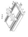
- Such a vision measuring apparatus includes, for example, as shown in Fig. 8, a stage glass 210 as a stage for setting an object W to be measured thereon, an imaging device 514 for imaging the object W, an illuminator 700 that performs contour illumination against the object W through the stage glass 210, a movement mechanism 600 for moving the imaging device 514 and the illuminator 700 in accordance with the portion to be measured of the object W and an analyzing unit (not shown) for analyzing and processing images taken by the imaging device 514.
- the stage glass 210 has a stage surface 211 on which an object W to be measured is set, and the stage surface 211 is formed into a flat plane free from unevenness, waviness or the like.
- a movement mechanism 600 is equipped with a Y-movement mechanism 610 that moves the imaging device 514 and the illuminator 700 along the Y-direction, which is one of the parallel direction to the stage surface 211 of the stage glass 210, and an X-movement mechanism 620 that moves the imaging device 514 and the illuminator 700 along the X-direction, which is parallel to the stage surface 211 and perpendicular to the Y-direction.
- the Y-movement mechanism 610 is equipped with Y-axis guides 611, 611, which are disposed parallel to each other within a flat plane parallel to the stage surface 211 interposing the stage glass 210, and Y-sliders 612, 612 arranged in slidable manner on each of the Y-axis guides 611, 611.
- the X-movement mechanism 620 is equipped with a first X-axis guide 621 of which both legs are fixedly attached to the Y-sliders 612, 612, and are disposed parallel to the stage glass 210 facing the stage surface 211 side of the stage glass 210, a second X-axis guide 622 of which both legs are fixedly attached to the Y-sliders 612, 612 and are disposed parallel to the stage glass 210 facing at the opposite side of the stage surface 211 of the stage glass 210, a first X-slider 623 mounted in slidable manner on the first X-axis guide 621 and a second X-slider 624 mounted in slidable manner on the second X-axis guide 622.
- the imaging device 514 is attached to the first X-slider 623, and the illuminator 700 is attached to the second X-slider 624.
- a display-panel for example, is set on the stage surface 211 of the stage glass 210 as an object W to be measured.
- the imaging device 514 and the illuminator 700 are moved by the Y-movement mechanism 610 and the X-movement mechanism 620 in accordance with the portion to be measured.
- images of the object W are taken by the imaging device 514.
- an analyzing unit (not shown) analyzes the images based on the image data, and the contour and dimensions of the object W are measured.
- a display panel as an object W has 2500 mm ⁇ 2500 mm in size.
- the size of the stage glass 210 for setting such a large object W also has to be made larger.
- stage glass 210 is simply made larger, flexure is generated due to its own weight. For example, in a glass of 25 mm in thickness and 2500 mm x 2500 mm in size, the flexure due to its own weight reaches to an extent of 0.8 mm to 1.8 mm.
- the stage glass 210 deflects as described above, the object W also deflects; thus, there resides such a problem that the measurement is hardly carried out precisely.
- the jacks block movement of the illuminator 700 bringing about areas out of reach and thus areas with no illumination are generated.
- An object of the present invention is to provide a stage apparatus and a vision measuring apparatus, which is capable of maintaining the flatness of a stage surface as well as permitting upsizing.
- a stage apparatus includes: a light transmittance plate having on an upper surface side a stage surface of a substantially flat plane on which a predetermined workpiece is set; a plane light emitter having a flat plane provided to substantially all over a lower surface of the light transmittance plate to illuminate the workpiece with contour illumination through the light transmittance plate; and a flatness adjuster that supports a lower face side of the plane light emitter at a plurality of points and adjusts the flatness of the stage surface by adjusting the height at a plurality of supporting points.
- the flatness adjuster adjusts the flatness of the stage surface. Accordingly, the stage surface is always maintained to be flat. For example, when images of a workpiece set on the stage surface are taken and measured, the measurement accuracy is improved.
- the contour illumination can be performed in substantially all over the light transmittance plate without moving the illuminator. Accordingly, by eliminating the movement mechanism, cost for components and assembly process can be reduced.
- the movement mechanism for moving the illuminator is eliminated. Accordingly, the flatness adjuster for adjusting the flatness of the light transmittance plate from the lower face side of the light transmittance plate can be installed. Thus, even when the light transmittance plate is upsized, the flatness of the light transmittance plate can be maintained by adjusting the flatness thereof using the flatness adjuster.
- the contour illumination can be performed on substantially all over the light transmittance plate while maintaining the flatness of a large sized light transmittance plate having as large as 2500 mm in length for one side. Accordingly, the present invention is extremely suitable for illuminating a large sized display panel or the like with the contour illumination.
- the light transmittance plate does not have to maintain the flatness of the stage surface with the rigidity of its own. Accordingly, the rigidity of the light transmittance plate may be lower, and the thickness of the light transmittance plate may be thinner. As a result, material cost can be reduced.
- the light transmittance plate is formed of, for example, an inorganic glass.
- the light transmittance plate may be formed of, for example, an organic glass consisting of a light transmissive resin (for example, acrylic resin).
- the flatness adjuster may be a plurality of supporters disposed at a plurality of predetermined positions on a lower face side of the plane light emitter and having supports capable of moving in a vertical direction.
- the flatness of the stage surface can be adjusted to have an even height.
- the flatness adjuster may includes: a plurality of height detectors that detect the height at a plurality of predetermined points on the lower face side of the plane light emitter; and a controller that controls the height at the plurality of predetermined points supporting the lower face side of the plane light emitter based on a detection result by the height detectors.
- the height at the plurality of predetermined points can be controlled to be an even height by the controller.
- the flatness of the stage surface is always maintained automatically.
- a stage apparatus includes: a light transmittance plate having on an upper surface a stage surface of a substantially flat plane on which a predetermined workpiece is set; a plane light emitter having a flat plane provided to substantially all over a lower surface of the light transmittance plate to illuminate the workpiece with contour illumination through the light transmittance plate; and a base plate having a predetermined rigidity provided on an opposite side to the light transmittance plate interposing the plane light emitter.
- the base plate gives the rigidity thereof to the light transmittance plate, and the flatness of the stage surface is maintained.
- the rigidity given to the light transmittance plate by the base plate can provide an equivalent effect of processing a rigid material surface, and accordingly the stage surface can be processed to a flat plane with a high precision.
- the plane light emitter may be divided into a plurality of parts and light emission is controlled at each of the parts independently.
- the power consumption can be reduced.
- the power consumption is largely reduced.
- the plane light emitter is, for example, an EL or the like, to obtain the same luminance, the smaller is the light emitting area the lower is the voltage required.
- the power consumption can be considerably reduced.
- the heat from the plane light emitter can be reduced.
- the heat from the plane light emitter can be reduced.
- the stage apparatus is employed, for example, in a measuring instrument, the measurement accuracy can be improved.
- the stage apparatus may further include a light reflection plate provided on an opposite side to the light transmittance plate interposing the plane light emitter.
- the light reflection plate reflects also the light, which is emitted toward the opposite side to the light transmittance plate; and thus, the entire light emitted from the plane light emitter can be oriented toward the light transmittance plate. Therefore, the luminance of the contour illumination is increased. Accordingly, for example, minute contour of the workpiece set on the light transmittance plate can be detected clearly.
- the stage apparatus not only may preferably includes a light reflection plate provided on an opposite side to the light transmittance plate interposing the plane light emitter, in the stage apparatus, but also the plane light emitter may preferably be divided into a plurality of parts and light emission is controlled at each of the parts independently.
- a vision measuring apparatus includes: a stage apparatus; an imaging device for imaging a workpiece set on the stage surface of the stage apparatus; a movement mechanism for moving the workpiece and the imaging device in three-dimensional directions; and an analyzing unit that analyzes the contour or dimensions of the workpiece based on image data taken by the imaging device.
- the analyzing unit analyzes the contour and dimensions of the workpiece based on the image data taken by the imaging device.
- the vision measuring apparatus of the present invention is suitable for vision measuring of a large workpiece such as a large size display panel. Further, the stage surface is maintained to be a flat plane with high precision. Owing to this, in addition to the fact that the measurement accuracy is improved, since the imaging device, for example, requires only one time focus adjustment, the measuring efficiency is enhanced.
- Fig. 1 is a sectional view of a stage apparatus; and Fig. 2 is a perspective view of the stage apparatus.
- the stage apparatus 100 includes a stage section 200 on which a predetermined workpiece W is set up and which illuminates the workpiece W from the lower face side thereof, and a supporting section (flatness adjuster) 300 that supports the stage section 200 and adjusts flatness of the stage section 200.
- the stage section 200 includes a stage glass (light transmittance plate) 210 having a stage surface 211 on the upper surface thereof, the stage surface 211 being processed into a flat plane, a plane light emitter 220, which is bonded to substantially all over the stage glass 210 at the lower surface of the stage glass 210, and a light reflection plate 230 bonded to the lower surface of the plane light emitter 220.
- a stage glass light transmittance plate
- the stage glass 210 is a plate glass having a relatively large area of, for example, 2500 mm x 2500 mm.
- the thickness is not required to be so large. For example, a thickness of approximately 10 mm to 25 mm will fit the purpose.
- the plane light emitter 220 is formed of a light emitting material having a flat plane, which emits the light when a predetermined voltage is applied.
- a predetermined voltage for example, an organic or inorganic EL (electroluminescence) may be employed.
- the voltage is applied to the plane light emitter 220 from a predetermined drive circuit (not shown), which controls the light emitting of the plane light emitter 220.
- the light reflection plate 230 is a thin plate for reflecting the light; thereby the light emitted from the plane light emitter 220 is reflected toward the stage glass 210.
- the supporting section 300 includes a plurality of jacks (supporters) 310 evenly disposed under the lower surface of the light reflection plate 230.
- the jacks 310 are disposed at the four corners and at the center of the stage section 200.
- Each of the jacks 310 includes a rod (support) 311 that is brought into contact with the lower surface of the light reflection plate 230 and supports the stage section 200, and a cylindrical holder 312 that holds the rod 311 movably in the vertical direction.
- the stage apparatus 100 is installed on a predetermined fixed surface 900.
- the flatness of the stage surface 211 is checked.
- the flatness of the stage surface 211 is out of allowable range because of a fact that, for example, the central area is hollow due to a deflection of the stage glass 210
- the flatness of the stage glass 210 is adjusted by moving rods 311 of the jacks 310 in the vertical direction.
- the workpiece W is set on the stage surface 211 and the plane light emitter 220 is energized to emit the light. Then, the workpiece W is illuminated with the contour illumination through the stage glass 210.
- Fig. 5 shows a configuration of a vision measuring system 500 as a vision measuring apparatus.
- the vision measuring system 500 includes a vision measuring machine 510, a control unit 520, an input unit 530 and an output unit 540.
- the vision measuring machine 510 includes a console table 511, which serves as a base, a stage section 512 disposed on the console table 511 on which a workpiece W is set, an imaging device 514 for imaging the workpiece W and a movement mechanism 515 that moves the imaging device 514 and the workpiece W in the three-dimensional directions.
- the stage section 512 includes a base 513 having a receiving space opened upwardly and a stage apparatus 100 provided in the receiving space on the base 513.
- stage apparatus 100 one of the stage apparatus, which has been described so far in the first, second and third embodiments, may be utilized.
- a CCD camera may be employed.
- the movement mechanism 515 includes beam supporters 516 and 516, which are provided vertically on the both side edges of the base 513 so as to be movable forward and backward, an X-beam 517 supported by the upper ends of the beam supporters 516 and 516, and a Z-slider 518 disposed in the X-beam 517 so as to be slidable thereon.
- the imaging device 514 Being pendent vertically from the Z-slider 518, the imaging device 514 is attached to the front end of the Z-slider 518.
- the configuration to provide the beam supporters 516 and 516 to be movable along the sides of the base 513 (in the Y-direction) the following configuration is given as an example. That is, as shown in Fig. 6 showing internal structure, the beam supporters 516 are supported by guide rails 519A on the both sides of the console table 511, and engaged with lead screws 519B to move the beam supporters 516. Note that such a configuration may be employed that the beam supporters 516 and 516 are fixed to the base 513, and the stage apparatus 100 slides to move within the receiving space (in the Y-direction).
- the control unit 520 includes a motion controller 521 that controls the movement of the movement mechanism 515 and a host computer 522 that analyzes the contour and dimensions of the workpiece W based on the image data taken by the imaging device 514.
- the motion controller 521 may be adapted to control the jacks (310, 410) of the stage apparatus 100 to adjust the flatness of the stage surface 211, or to control the voltage to be applied to the plane light emitter 220 to control the light emission of the plane light emitter 220.
- a keyboard or the like is given as an example; and as the output unit, a monitor, a printer or the like is given as an example.
- a workpiece W is set on the stage surface 211 of the stage apparatus 100. Owing to the flatness adjuster (supporting section), the flatness of the stage surface 211 is adjusted to be a flat plane free from unevenness or waviness.
- contour illumination is performed from the lower surface of the workpiece W by light emission of the plane light emitter 220 through the stage glass 210.
- the movement mechanism 515 is driven and the imaging device 514 is moved in accordance with the area to be measured in the workpiece W. And then, the imaging device 514 takes images of the workpiece W.
- the analyzing unit (not shown) of the host computer 522 analyzes the image data, and the contour and dimensions of the workpiece W are output through the output unit 540.
- the modification 1 configured as described above, in addition to the effects of the embodiments described so far, the following effect can be obtained.
- the light transmittance plate may be formed from an organic glass.
- the stage glass, the plane light emitter and the light reflection plate may be divided into a plurality of parts of tile shapes, and the control of the light emission by the plane light emitter and the control of the height adjustment by the jacks are carried out for each part independently.
- the plane light emitter is divided into a plurality of parts as shown in Fig. 7, it is preferred to provide a light reflection plate at the opposite side to the stage glass interposing the plane light emitter in order to prevent dark area generated in the joint area between the parts.
- the stage apparatus is incorporated with the vision measuring apparatus. It is needless to say that, in addition to the above, the stage apparatus may be incorporated with, for example, an optical measuring instrument such as a microscope or the like.
Landscapes
- Physics & Mathematics (AREA)
- General Physics & Mathematics (AREA)
- Length Measuring Devices By Optical Means (AREA)
- Length Measuring Devices With Unspecified Measuring Means (AREA)
- Electroluminescent Light Sources (AREA)
Abstract
Description
(5) Since it is possible to form a
Claims (7)
- A stage apparatus (100), comprising:a light transmittance plate (210) having on an upper surface side a stage surface (211) of a substantially flat plane on which a predetermined workpiece (W) is set;a plane light emitter (220) having a flat plane provided to substantially all over a lower surface of the light transmittance plate (210) to illuminate the workpiece (W) with contour illumination through the light transmittance plate (210); anda flatness adjuster (300) that supports a lower face side of the plane light emitter (220) at a plurality of points and adjusts the flatness of the stage surface (211) by adjusting the height at a plurality of supporting points.
- The stage apparatus (100) according to claim 1, wherein the flatness adjuster (300) is a plurality of supporters (310) disposed at a plurality of predetermined positions on a lower face side of the plane light emitter (220) and having supports (311) capable of moving in a vertical direction.
- The stage apparatus (100) according to claim 1 or claim 2,
the flatness adjuster (300) including:a plurality of height detectors (420) that detect the height at a plurality of predetermined points on the lower face side of the plane light emitter (220); anda controller (430) that controls the height at the plurality of predetermined points supporting the lower face side of the plane light emitter (220) based on a detection result by the height detectors (420). - A stage apparatus (100), comprising:a light transmittance plate (210) having on an upper surface a stage surface (211) of a substantially flat plane on which a predetermined workpiece (W) is set;a plane light emitter (220) having a flat plane provided to substantially all over a lower surface of the light transmittance plate (210) to illuminate the workpiece (W) with contour illumination through the light transmittance plate (210); anda base plate (240) having a predetermined rigidity provided on an opposite side to the light transmittance plate (210) interposing the plane light emitter (220).
- The stage apparatus (100) according to any of claim 1 to claim 4, wherein the plane light emitter (220) is divided into a plurality of parts and light emission is controlled at each of the parts independently.
- The stage apparatus (100) according to any of claim 1 to claim 5, further comprising a light reflection plate (230) provided on an opposite side to the light transmittance plate (210) interposing the plane light emitter (220).
- A vision measuring apparatus (500), comprising:the stage apparatus (100) according to any of claim 1 to claim 6;an imaging device (514) for imaging a workpiece (W) set on the stage surface (211) of the stage apparatus (100);a movement mechanism (515) for moving the workpiece (W) and the imaging device (514) in three-dimensional directions; andan analyzing unit that analyzes the contour or dimensions of the workpiece (W) based on image data taken by the imaging device (514).
Applications Claiming Priority (2)
| Application Number | Priority Date | Filing Date | Title |
|---|---|---|---|
| JP2004174353A JP4469659B2 (en) | 2004-06-11 | 2004-06-11 | Mounting table device, image measuring device |
| JP2004174353 | 2004-06-11 |
Publications (3)
| Publication Number | Publication Date |
|---|---|
| EP1605228A2 true EP1605228A2 (en) | 2005-12-14 |
| EP1605228A3 EP1605228A3 (en) | 2006-01-25 |
| EP1605228B1 EP1605228B1 (en) | 2007-08-15 |
Family
ID=34937379
Family Applications (1)
| Application Number | Title | Priority Date | Filing Date |
|---|---|---|---|
| EP05012573A Ceased EP1605228B1 (en) | 2004-06-11 | 2005-06-10 | Stage apparatus and vision measuring apparatus |
Country Status (5)
| Country | Link |
|---|---|
| US (2) | US7430050B2 (en) |
| EP (1) | EP1605228B1 (en) |
| JP (1) | JP4469659B2 (en) |
| CN (1) | CN100520375C (en) |
| DE (1) | DE602005001977T2 (en) |
Cited By (2)
| Publication number | Priority date | Publication date | Assignee | Title |
|---|---|---|---|---|
| WO2014122438A1 (en) * | 2013-02-05 | 2014-08-14 | Renishaw Plc | A method and apparatus for use in machine vision |
| CN121252649A (en) * | 2025-11-10 | 2026-01-02 | 浙江匠选科技有限公司 | Large-field flash tester |
Families Citing this family (19)
| Publication number | Priority date | Publication date | Assignee | Title |
|---|---|---|---|---|
| JP2008082705A (en) * | 2006-09-25 | 2008-04-10 | Olympus Corp | Transmission illumination stage and substrate inspection device |
| JP4953213B2 (en) * | 2008-08-26 | 2012-06-13 | 株式会社日本マイクロニクス | Table height adjustment mechanism and height adjustment table using the same |
| JP5349122B2 (en) * | 2009-04-14 | 2013-11-20 | 株式会社ミツトヨ | Synchronous moving device and image measuring device |
| CN102338629A (en) * | 2010-07-27 | 2012-02-01 | 新杰科技股份有限公司 | Continuous Measurement Method of Plate Thickness |
| US9080865B2 (en) * | 2012-12-27 | 2015-07-14 | Shenzhen China Star Optoelectronics Technology Co., Ltd | Orthogonality compensation method for length measurement device and length measurement device using same |
| CN103063383B (en) * | 2013-01-10 | 2017-07-11 | 芜湖东旭光电科技有限公司 | A kind of deflection measuring apparatus of flat display substrate glass |
| CN104677322B (en) * | 2013-11-30 | 2017-07-21 | 富泰华工业(深圳)有限公司 | Detection means |
| US10529260B2 (en) * | 2015-12-29 | 2020-01-07 | Christie Digital Systems Usa, Inc. | System for mounting a plurality of display units |
| CN108106996B (en) * | 2017-12-25 | 2024-05-28 | 通彩智能科技集团有限公司 | A glass detection and holding platform |
| JP7343314B2 (en) * | 2018-07-12 | 2023-09-12 | 住友化学株式会社 | Stage, physical property measuring device and measuring method |
| CN109443235A (en) * | 2018-11-02 | 2019-03-08 | 滁州市云米工业设计有限公司 | A kind of industrial design product collecting device for outline |
| JP7153231B2 (en) * | 2018-12-21 | 2022-10-14 | 日本電気硝子株式会社 | Glass plate deflection measuring device and glass plate manufacturing method |
| WO2020154385A1 (en) | 2019-01-24 | 2020-07-30 | Steelcase Inc. | Display support system and method for the use thereof |
| CN111769028B (en) * | 2020-06-24 | 2023-03-21 | 上海理工大学 | Glass negative flatness correction device and method |
| CN115918281A (en) | 2020-07-23 | 2023-04-04 | 斯蒂尔凯斯有限公司 | Monitor Mount System and How to Use It |
| CN112305745B (en) * | 2020-11-10 | 2023-05-26 | 华中科技大学鄂州工业技术研究院 | High-temperature confocal microscope |
| CN113935937B (en) * | 2021-11-02 | 2025-11-18 | 百度在线网络技术(北京)有限公司 | Image processing methods, apparatuses, electronic devices, media and systems |
| CN114234807B (en) * | 2021-12-17 | 2024-04-26 | 南京苏胜天信息科技有限公司 | Object multi-dimensional size detection device based on machine vision |
| CN116901271A (en) * | 2023-07-31 | 2023-10-20 | 西安奕斯伟材料科技股份有限公司 | Support device, cutting device and support method for crystal bar |
Family Cites Families (11)
| Publication number | Priority date | Publication date | Assignee | Title |
|---|---|---|---|---|
| US4654762A (en) * | 1985-04-01 | 1987-03-31 | Wizer Equipment, Inc. | Light table |
| GB8800570D0 (en) | 1988-01-12 | 1988-02-10 | Leicester Polytechnic | Measuring method |
| JP3278551B2 (en) | 1995-07-20 | 2002-04-30 | 株式会社ソキア | Glass measuring table |
| JPH09178911A (en) * | 1995-12-26 | 1997-07-11 | Bridgestone Corp | Light diffusing sheet |
| DE19805040A1 (en) * | 1998-02-09 | 1999-08-12 | Wegu Messtechnik | Optical co-ordinate measuring machine using light transmission |
| JP4192316B2 (en) | 1998-11-13 | 2008-12-10 | 株式会社ニコン | Stage |
| DE19902401C2 (en) | 1999-01-22 | 2001-02-01 | Wohlenberg Schneidesysteme Gmb | Method and device for determining the geometry of sheet-like material or stacks thereof |
| JP4150474B2 (en) | 1999-07-28 | 2008-09-17 | 株式会社ミツトヨ | Method and apparatus for correcting table deflection of image measuring machine |
| JP2002207004A (en) | 2001-01-09 | 2002-07-26 | Mitsutoyo Corp | Image measuring instrument |
| US6999212B2 (en) * | 2001-07-10 | 2006-02-14 | Che-Kuei Mai | Back-light module for image scanning device and method for calibrating illumination with the back-light module |
| US20030053045A1 (en) * | 2001-09-20 | 2003-03-20 | Doering John W. | System for inspecting a flat sheet workpiece |
-
2004
- 2004-06-11 JP JP2004174353A patent/JP4469659B2/en not_active Expired - Fee Related
-
2005
- 2005-06-08 US US11/147,385 patent/US7430050B2/en active Active
- 2005-06-10 DE DE602005001977T patent/DE602005001977T2/en not_active Expired - Lifetime
- 2005-06-10 EP EP05012573A patent/EP1605228B1/en not_active Ceased
- 2005-06-13 CN CNB2005100766717A patent/CN100520375C/en not_active Expired - Fee Related
-
2008
- 2008-08-21 US US12/230,012 patent/US20090002723A1/en not_active Abandoned
Cited By (3)
| Publication number | Priority date | Publication date | Assignee | Title |
|---|---|---|---|---|
| WO2014122438A1 (en) * | 2013-02-05 | 2014-08-14 | Renishaw Plc | A method and apparatus for use in machine vision |
| US10775159B2 (en) | 2013-02-05 | 2020-09-15 | Renishaw Plc | Method and apparatus for illumination and inspection of an object in a machine vision apparatus |
| CN121252649A (en) * | 2025-11-10 | 2026-01-02 | 浙江匠选科技有限公司 | Large-field flash tester |
Also Published As
| Publication number | Publication date |
|---|---|
| DE602005001977T2 (en) | 2008-04-30 |
| DE602005001977D1 (en) | 2007-09-27 |
| US20050275803A1 (en) | 2005-12-15 |
| US7430050B2 (en) | 2008-09-30 |
| EP1605228A3 (en) | 2006-01-25 |
| JP4469659B2 (en) | 2010-05-26 |
| JP2005351810A (en) | 2005-12-22 |
| US20090002723A1 (en) | 2009-01-01 |
| EP1605228B1 (en) | 2007-08-15 |
| CN100520375C (en) | 2009-07-29 |
| CN1707248A (en) | 2005-12-14 |
Similar Documents
| Publication | Publication Date | Title |
|---|---|---|
| US20090002723A1 (en) | Stage apparatus and vision measuring apparatus | |
| JP5863547B2 (en) | Printed circuit board inspection equipment | |
| TW528881B (en) | Position measuring apparatus | |
| US8139229B2 (en) | Calibrating jig, profile measuring device, and method of offset calculation | |
| CN101308099A (en) | Optical inspection device | |
| JP2023090913A (en) | Side inspection equipment for semiconductor devices | |
| CN211669102U (en) | Substrate inspection device | |
| CN101101452A (en) | Exposure device | |
| US6958769B2 (en) | High resolution sheet metal scanner with independent tracking light source | |
| JP2006200917A (en) | Coordinates detecting device and test object inspecting device | |
| WO2022083084A1 (en) | Universal flash measurement instrument | |
| JP2007078635A (en) | Calibration jig and image measuring machine offset calculation method | |
| CN100535590C (en) | Basal lamina determination device | |
| CN210165929U (en) | Measuring machine | |
| CN210533669U (en) | A lens MTF detection tool | |
| JPH0712512A (en) | Two-dimensional coordinate measuring machine | |
| JP2006266748A (en) | Image measurement device | |
| JPWO2003002934A1 (en) | Coordinate detection device | |
| JP2007033202A (en) | Visual inspection apparatus and visual inspection method | |
| JP4431479B2 (en) | 2D coordinate measuring machine | |
| JP2007107884A (en) | Substrate inspection apparatus and substrate inspection method | |
| KR102003468B1 (en) | Apparatus for Maintaining Gap of Substrate | |
| KR20160125884A (en) | Measuring apparatus | |
| CN223581744U (en) | Detection device based on machine vision | |
| CN223581743U (en) | Silk screen printing net plate detection device |
Legal Events
| Date | Code | Title | Description |
|---|---|---|---|
| PUAI | Public reference made under article 153(3) epc to a published international application that has entered the european phase |
Free format text: ORIGINAL CODE: 0009012 |
|
| PUAL | Search report despatched |
Free format text: ORIGINAL CODE: 0009013 |
|
| AK | Designated contracting states |
Kind code of ref document: A2 Designated state(s): AT BE BG CH CY CZ DE DK EE ES FI FR GB GR HU IE IS IT LI LT LU MC NL PL PT RO SE SI SK TR |
|
| AX | Request for extension of the european patent |
Extension state: AL BA HR LV MK YU |
|
| AK | Designated contracting states |
Kind code of ref document: A3 Designated state(s): AT BE BG CH CY CZ DE DK EE ES FI FR GB GR HU IE IS IT LI LT LU MC NL PL PT RO SE SI SK TR |
|
| AX | Request for extension of the european patent |
Extension state: AL BA HR LV MK YU |
|
| 17P | Request for examination filed |
Effective date: 20060711 |
|
| AKX | Designation fees paid |
Designated state(s): DE FR GB |
|
| 17Q | First examination report despatched |
Effective date: 20060914 |
|
| GRAP | Despatch of communication of intention to grant a patent |
Free format text: ORIGINAL CODE: EPIDOSNIGR1 |
|
| GRAS | Grant fee paid |
Free format text: ORIGINAL CODE: EPIDOSNIGR3 |
|
| GRAA | (expected) grant |
Free format text: ORIGINAL CODE: 0009210 |
|
| AK | Designated contracting states |
Kind code of ref document: B1 Designated state(s): DE FR GB |
|
| REG | Reference to a national code |
Ref country code: GB Ref legal event code: FG4D |
|
| REF | Corresponds to: |
Ref document number: 602005001977 Country of ref document: DE Date of ref document: 20070927 Kind code of ref document: P |
|
| ET | Fr: translation filed | ||
| PLBE | No opposition filed within time limit |
Free format text: ORIGINAL CODE: 0009261 |
|
| STAA | Information on the status of an ep patent application or granted ep patent |
Free format text: STATUS: NO OPPOSITION FILED WITHIN TIME LIMIT |
|
| 26N | No opposition filed |
Effective date: 20080516 |
|
| REG | Reference to a national code |
Ref country code: FR Ref legal event code: PLFP Year of fee payment: 12 |
|
| REG | Reference to a national code |
Ref country code: FR Ref legal event code: PLFP Year of fee payment: 13 |
|
| REG | Reference to a national code |
Ref country code: FR Ref legal event code: PLFP Year of fee payment: 14 |
|
| PGFP | Annual fee paid to national office [announced via postgrant information from national office to epo] |
Ref country code: FR Payment date: 20200619 Year of fee payment: 16 Ref country code: DE Payment date: 20200618 Year of fee payment: 16 |
|
| PGFP | Annual fee paid to national office [announced via postgrant information from national office to epo] |
Ref country code: GB Payment date: 20200625 Year of fee payment: 16 |
|
| REG | Reference to a national code |
Ref country code: DE Ref legal event code: R119 Ref document number: 602005001977 Country of ref document: DE |
|
| GBPC | Gb: european patent ceased through non-payment of renewal fee |
Effective date: 20210610 |
|
| PG25 | Lapsed in a contracting state [announced via postgrant information from national office to epo] |
Ref country code: GB Free format text: LAPSE BECAUSE OF NON-PAYMENT OF DUE FEES Effective date: 20210610 Ref country code: DE Free format text: LAPSE BECAUSE OF NON-PAYMENT OF DUE FEES Effective date: 20220101 |
|
| PG25 | Lapsed in a contracting state [announced via postgrant information from national office to epo] |
Ref country code: FR Free format text: LAPSE BECAUSE OF NON-PAYMENT OF DUE FEES Effective date: 20210630 |