EP1604936A1 - Aufzugsanlage mit Ausgleichsmittelführung - Google Patents
Aufzugsanlage mit Ausgleichsmittelführung Download PDFInfo
- Publication number
- EP1604936A1 EP1604936A1 EP05101804A EP05101804A EP1604936A1 EP 1604936 A1 EP1604936 A1 EP 1604936A1 EP 05101804 A EP05101804 A EP 05101804A EP 05101804 A EP05101804 A EP 05101804A EP 1604936 A1 EP1604936 A1 EP 1604936A1
- Authority
- EP
- European Patent Office
- Prior art keywords
- compensating means
- brush
- brushes
- installation according
- elevator
- Prior art date
- Legal status (The legal status is an assumption and is not a legal conclusion. Google has not performed a legal analysis and makes no representation as to the accuracy of the status listed.)
- Withdrawn
Links
- 238000009434 installation Methods 0.000 claims abstract description 19
- 238000005192 partition Methods 0.000 claims description 20
- 239000000463 material Substances 0.000 claims description 3
- 239000004952 Polyamide Substances 0.000 claims description 2
- 239000004743 Polypropylene Substances 0.000 claims description 2
- 229920002647 polyamide Polymers 0.000 claims description 2
- -1 polypropylene Polymers 0.000 claims description 2
- 229920001155 polypropylene Polymers 0.000 claims description 2
- 239000000725 suspension Substances 0.000 abstract 1
- 239000003795 chemical substances by application Substances 0.000 description 6
- 238000011161 development Methods 0.000 description 4
- 230000018109 developmental process Effects 0.000 description 4
- 230000001419 dependent effect Effects 0.000 description 3
- 230000001447 compensatory effect Effects 0.000 description 2
- 238000013016 damping Methods 0.000 description 2
- 239000004033 plastic Substances 0.000 description 2
- 229920003023 plastic Polymers 0.000 description 2
- ZOXJGFHDIHLPTG-UHFFFAOYSA-N Boron Chemical compound [B] ZOXJGFHDIHLPTG-UHFFFAOYSA-N 0.000 description 1
- 229910052796 boron Inorganic materials 0.000 description 1
- 238000012423 maintenance Methods 0.000 description 1
- 230000010355 oscillation Effects 0.000 description 1
Images

Classifications
-
- B—PERFORMING OPERATIONS; TRANSPORTING
- B66—HOISTING; LIFTING; HAULING
- B66B—ELEVATORS; ESCALATORS OR MOVING WALKWAYS
- B66B7/00—Other common features of elevators
- B66B7/06—Arrangements of ropes or cables
- B66B7/068—Cable weight compensating devices
Definitions
- the subject of the invention is an elevator installation with compensating means guidance, as defined in the claims.
- Comppensating means means a rope, ribbon or chain, to understand flexible means, each at one of its suspended from both ends of the elevator car or on the counterweight is and forms a hanging compensator clew. Purpose of the compensating means is that of the cabin position dependent effect of the weight of the support and drive means (Carrying ropes, carrying strap) on the at the traction sheave to compensate for required driving force.
- An equalizer guide as disclosed in US 6,488,125, has certain disadvantages. It requires a relatively large installation space, which is not available in certain elevator concepts. In the case of metallic contact between compensating means and guide rollers noise is generated. The rigidly mounted rollers can not dampen vibrations occurring in the compensating means.
- the present invention is based on the object, a Device of the type described above to provide, does not have the disadvantages mentioned, in particular Requires less installation space, less noise and less noise Vibration of the compensating effectively attenuates.
- the invention is therefore based on the idea of one in one Elevator shaft at the elevator cabin and counterweight hanging Compensate with the help of brushes.
- a brush is an object that somehow formed body - the brush body - includes, in which Bristles, d. H. slim rods with a small cross-section, are fixed individually or in tufts.
- elevator shaft is essentially that of the cabin and to understand the counterweight as a travel area claimed space whereby shaft walls do not necessarily have to be present.
- the Equalizer guide equipped with more than one brush.
- the hanging compensating means at several Bodies and / or be guided in different directions.
- the compensating means guide a number of brushes which are arranged so that they are in Range of deflection of the compensating means the deflections the compensating means transverse to the deflection direction and / or in Direction of the deflection of the compensating means and / or in Limit vertical direction.
- a brush holder in that in the shaft space, usually in the area the lower end of the shaft or at the bottom of a Shaft pit, a brush holder is permanently installed.
- This Brush holder for example, in the form of a profile frame or a panel frame, and so on designed that the brushes in a suitable position and attach to it.
- the brushes as Rod brushes - also known as strip brushes - trained.
- the bristles are preferably on the narrow Side of an elongated, prismatic brush body with in Substantially flat-rectangular cross section used.
- the brushes designed as a so-called round brush.
- bristles are in the radial direction in a cylindrical Brush body used.
- a round brush is suitable especially as a guide of the compensator in a concave Zone of his diversion.
- the round brush can only be part of it a complete cylinder, for example in the form of a half-cylinder.
- the Austiciansmittel a round brush included, the rotatable -
- the rotatable - For example, in combination with bearings - in Brush holder is held.
- Such is particularly suitable to avoid grinding noise in places where relative high executives are required.
- the brush body serve or help, the brush body in the Area of an edge of a plate-shaped part of the brush holder to fix.
- additional aids such as screws, Braces, Briden, cable ties, etc. used.
- the brush bodies of the brushes are such connected to the brush holder, that the brushes in Direction of their bristles, d. H. towards the compensatory agent or away from it, let move.
- screw connections are suitable in combination with slots in the brush body or connections with spring clips.
- brushes are used whose bristles are made of plastics, preferably of polyamide or polypropylene.
- natural bristles may also be used, for example horsehair bristles or pig bristles.
- the bristle material, the bristle diameter and the bristle length, wear resistance, noise development and damping properties of the compensating agent guide can be optimized. Damping property is the suitability of the brush to prevent or mitigate oscillations of the compensating means within as well as outside the guiding area.
- a particularly expedient embodiment of the invention is that the brush holder by a plate or sheet-like partition is formed in the bottom Shaft area occupied by the counterweight space from separates remaining shaft space.
- a partition is in Elevator standards required to prevent an im lowest shaft area (in the pit) present Maintenance person injured by the downhill counterweight can be.
- a compensating means that, as described above, between elevator car and counterweight in the form of a compensator loop is suspended and in the lowest shaft area a diversion has, this deflection is located in the region of the partition.
- the compensating means must therefore pass through an opening in be passed through the partition.
- the partition wall in the region of said opening used as a brush holder for brushes, which the compensating agent in the area of its diversion.
- Fig. 1 and 2 each show an inventive elevator system. Shown are in each case an elevator car 1 and a counterweight 2, which are installed in an elevator shaft 3, The elevator car 1 and the counterweight 2 hang on one Supporting means 4 and are about this by a drive unit 5 with a traction sheave 6 vertically along from - here not shown - guide rails moved. Between the Elevator car 1 and the counterweight 2 each depends Compensation 7 in the form of a loop, which with each one of its ends on the elevator car 1 or on the counterweight 2 is attached.
- Figs. 1 and 2 are two variants of a compensating means guide 8.1, 8.2 to recognize. These each have one Number of brushes 12.1, 12.2, which the compensating means 7 in the region of its deflection 7.1 transverse to the deflection, in Direction of the deflection, as well as lead in vertical direction, d. h., The possible deflection of the compensating means 7 off limit its intended location.
- the recognizable in Fig. 1 compensating means 8.1 comprises guidance a fixed in the shaft or shaft bottom brush frame 9.1, which performs the function of a brush holder.
- the Compensation means 8.1 is enlarged as detail A in Fig. 3 shown and related below Fig. 3 described in more detail.
- the partition wall 9.2 has a passage opening 9.2.1 above the bottom of the elevator shaft.
- the partition wall 9.2, ie in particular its lying in the region of said passage opening 9.2.1 part is used in the illustrated in Fig. 2 variant of a compensating means guide 8.2 as a brush holder for the brushes 12.1, 12.2.
- the compensating means guide 8.2 is shown enlarged as detail B in FIG. 4 and described in more detail below in connection with FIG. 4.
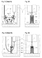
- FIG. 3 is the marked in Fig. 1 with A drawing detail shown enlarged to the details of the compensating means guide 8.1 to recognize, for example at the bottom of the shaft fixed brush frame 9.1 as Includes brush holder.
- FIG. 3A is a side view of FIG Fig. 3 shown compensating means guide.
- the compensatory agent 7, for example, as a wire rope, as open or in Plastic molded round link chain or as flat belt-like Tape with integrated high-density materials can be in the area of its diversion 7.1 between rod-shaped brushes 12.1, which on side parts 9.1.1, 9.1.2 of the brush frame 9.1 are attached and in Be referred to below as bar brushes 12.1.
- Bar brushes 12.1 provide with their against the compensating agent 7 directed bristles 13 for the guidance of the compensating means 7 transversely to the direction of deflection.
- the length of the Bar brushes 12.1 is designed so that changes the vertical position of the deflection 7.1 of the compensating means 7 are permissible in a measure dependent on the height of the lift.
- While 12.2 circular brushes are called, which extend from a side part 9.1.1 of the brush frame 9.1 to the opposite side part 9.1.2 and with their radially directed bristles 13 vertical deflections and possibly occurring vibrations of the compensating means 7 limit and damp.
- the round brushes may also be rotatable about their longitudinal axis and, for this purpose, may also be equipped with roller bearings.
- Non-rotating round brushes 12.2 need not be present as complete cylinders, ie they can also fulfill their function in a semi-cylindrical shape, as disclosed in FIG.
- Fig. 4 the marked in Fig. 2 with B drawing detail shown enlarged to the details of there shown variant of a compensating means guide 8.2 recognize allow.
- this compensating means guide 8.2 is the Brush holder by a plate or sheet-shaped partition 9.2 formed, which in the lowest shaft area of the Counterweight claimed shaft space of the by the Elevator car claimed shaft space separates.
- Fig. 4A is a side view of the compensating means guide shown in Fig. 4 looking towards the flat side of the mentioned Partition wall 9.2.
- This partition 9.2 is in its lower Area, d. H. in the area in which the diversion 7.1 of the elevator car and the counterweight 2 hanging Compensation 7 is located, with a passage opening 9.2.1 provided.
- the round brush 12.2 has the Task, the compensating means 7 to the said upper edge 14 of the passage opening 9.2.1 lead in the partition wall 9.2, at most occurring vibrations and jumps of the compensating means is reduced in the vertical direction and be steamed.
- the round brush 12.2 could also be around her Longitudinal axis to be rotatably mounted on the partition wall 9.2.
- the brushes 12.1, 12.2 shown in FIGS. 3, 3A, 4 and 4A basically consist of at least one rod-shaped or round brush body and therein fixed bristles 13 different Length and thickness.
- the brushes are with theirs Brush bodies by means of screws, clamps, cable ties or Briden, etc. on the brush holder (brush frame 9.1, partition 9.2). You can help improve the connection between brush body and brush holder in their brush bodies Have slots that - as in the round brush in Fig. 4A - allow the brush body on a Insert the edge of the brush holder.
- the brush body can for example, with screws through long holes or be fixed by elastic brackets, causing the Move brushes towards or out of the compensation means 7 leave to optimal distances between brush and Adjust compensator 7 and compensate for brush wear to be able to.
Landscapes
- Lift-Guide Devices, And Elevator Ropes And Cables (AREA)
Abstract
Description
Sie beansprucht einen relativ grossen Einbauraum, der bei gewissen Aufzugskonzepten nicht zur Verfügung steht. Im Fall von metallischer Berührung zwischen Ausgleichsmittel und Führungsrollen entsteht Lärm. Die starr gelagerten Rollen können im Ausgleichsmittel auftretende Schwingungen nicht dämpfen.
Durch geeignete Wahl des Borstenmaterials, der Borstendurchmesser und der Borstenlänge lassen sich Verschleissbeständigkeit, Geräuschentwicklung und Dämpfungseigenschaften der Ausgleichsmittelführung optimieren. Unter Dämpfungseigenschaft ist die Eignung der Bürste zu verstehen, Schwingungen des Ausgleichsmittels innerhalb aber auch ausserhalb des Führungsbereichs zu verhindern oder abzuschwächen.
- Fig. 1
- einen schematischen Querschnitt durch eine Aufzugsanlage mit einem Ausgleichsmittel und einer erfindungsgemässen Ausgleichsmittelführung mit Bürsten.
- Fig. 2
- einen schematischen Querschnitt durch eine Aufzugs anlage mit einem Ausgleichsmittel, einer im untersten Schachtbereich vorhandenen Trennwand zwischen Gegengewichtsraum und dem übrigen Schachtraum und einer in der Trennwand integrierten erfindungsgemässen Ausgleichsmittelführung mit Bürsten.
- Fig. 3
- einen vergrösserten Ausschnitt aus Fig. 1 mit Details der Ausgleichsmittelführung.
- Fig. 3A
- eine Seitenansicht der in Fig. 3 gezeigten Ausgleichsmittelführung.
- Fig. 4
- einen vergrösserten Ausschnitt aus Fig. 2 mit Details der in der Trennwand integrierten Ausgleichsmittelführung.
- Fig. 4A
- eine Seitenansicht der in Fig. 4 gezeigten Ausgleichsmittelführung mit Blickrichtung auf die flächige Seite der genannten Trennwand
Die Ausgleichsmittelführung 8.2 ist als Detail B in Fig. 4 vergrössert dargestellt und weiter unten im Zusammenhang mit Fig. 4 näher beschrieben.
Nicht rotierende Rundbürsten 12.2 müssen nicht als vollständige Zylinder vorhanden sein, d. h. sie können ihre Funktion auch halbzylinderförmig erfüllen, wie dies in Fig. 4 offenbart ist.
Claims (11)
- Aufzugsanlage, umfassenddadurch gekennzeichnet, dass die Ausgleichsmittelführung (8.1, 8.2) zum Führen des Ausgleichsmittels (7) mindestens eine Bürste (12.1, 12.2) aufweist.eine Aufzugskabine (1) und ein Gegengewicht (2),Tragmittel (4), die über mindestens eine im oberen Bereich der Aufzugsanlage angeordnete Scheibe laufen und die Aufzugskabine (1) wie auch das Gegengewicht (2) tragen,mindestens ein Ausgleichsmittel, das mit einem seiner beiden Enden an der Aufzugskabine (1) und mit dem anderen Ende am Gegengewicht (2) aufgehängt ist und eine hängende Schlaufe bildet,eine mindestens im Bereich einer Umlenkung (7.1) des Ausgleichsmittels (7) wirkende Ausgleichsmittelführung (8.1, 8.2),
- Aufzugsanlage nach Anspruch 1, dadurch gekennzeichnet, dass die Ausgleichsmittelführung (8.1, 8.2) mehrere Bürsten (12.1, 12.2) aufweist.
- Aufzugsanlage nach Anspruch 2, dadurch gekennzeichnet, dass die Bürsten (12.1, 12.2) so angeordnet sind, dass sie im Bereich der Umlenkung (7.1) des Ausgleichsmittels Auslenkungen des Ausgleichsmittels (7)begrenzen.quer zur Richtung der Umlenkung (7.1) des Ausgleichsmittels und/oderin Richtung der Umlenkung (7.1) des Ausgleichsmittels und/oderin Vertikalrichtung
- Aufzugsanlage nach Anspruch 3, dadurch gekennzeichnet, dass die Bürsten (12.1, 12.2) mit Borsten (13) versehen sind, deren Durchmesser von 0,15 mm bis 2 mm, und deren freie Länge von 5 mm bis 100 mm variiert.
- Aufzugsanlage nach Anspruch 4, dadurch gekennzeichnet, dass die Bürsten (12.1, 12.2) an einem im Schachtraum fix installierten Bürstenträger (9.1, 9.2) befestigt sind.
- Aufzugsanlage nach einem der Ansprüche 1 bis 5, dadurch gekennzeichnet, dass mindestens eine der Bürsten als Stabbürste (Streifenbürste) (12.1) ausgeführt ist.
- Aufzugsanlage nach einem der Ansprüche 1 bis 5, dadurch gekennzeichnet, dass mindestens eine der Bürsten als Rundbürste (12.2) oder als Teil einer Rundbürste ausgeführt ist.
- Aufzugsanlage nach einem der Ansprüche 1 bis 5, dadurch gekennzeichnet, dass mindestens eine der Bürsten als Rundbürste (12.2) ausgeführt und um ihre Längsachse drehbar angeordnet ist.
- Aufzugsanlage nach Anspruch 5, dadurch gekennzeichnet, dass eine Verbindung zwischen mindestens einem Bürstenkörper und dem Bürstenträger (9.1, 9.2) so ausgebildet ist, dass die Bürste (12.1, 12.2) in ihrer Distanz zum Ausgleichsmittel (7) verschiebbar ist.
- Aufzugsanlage nach Anspruch 4, dadurch gekennzeichnet, dass die Borsten (13) der Bürsten (12.1, 12.2) aus einem der folgenden Materialien bestehen:PolyamidPolypropylenPferdehaarSchweineborsten
- Aufzugsanlage nach Anspruch 5, dadurch gekennzeichnet, dass der Bürstenträger durch eine Trennwand (9.2) gebildet ist, die im untersten Schachtbereich den Bereich des vom Gegengewicht (2) beanspruchten Raums vom Rest des Schachtraums abtrennt.
Priority Applications (1)
| Application Number | Priority Date | Filing Date | Title |
|---|---|---|---|
| EP05101804A EP1604936A1 (de) | 2004-03-17 | 2005-03-09 | Aufzugsanlage mit Ausgleichsmittelführung |
Applications Claiming Priority (3)
| Application Number | Priority Date | Filing Date | Title |
|---|---|---|---|
| EP04006290 | 2004-03-17 | ||
| EP04006290 | 2004-03-17 | ||
| EP05101804A EP1604936A1 (de) | 2004-03-17 | 2005-03-09 | Aufzugsanlage mit Ausgleichsmittelführung |
Publications (1)
| Publication Number | Publication Date |
|---|---|
| EP1604936A1 true EP1604936A1 (de) | 2005-12-14 |
Family
ID=35311006
Family Applications (1)
| Application Number | Title | Priority Date | Filing Date |
|---|---|---|---|
| EP05101804A Withdrawn EP1604936A1 (de) | 2004-03-17 | 2005-03-09 | Aufzugsanlage mit Ausgleichsmittelführung |
Country Status (1)
| Country | Link |
|---|---|
| EP (1) | EP1604936A1 (de) |
Cited By (1)
| Publication number | Priority date | Publication date | Assignee | Title |
|---|---|---|---|---|
| CN106629320A (zh) * | 2015-10-30 | 2017-05-10 | 天津优安达电梯制造有限公司 | 一种电梯一体化补偿链导向滚轮 |
Citations (3)
| Publication number | Priority date | Publication date | Assignee | Title |
|---|---|---|---|---|
| JPH0761735A (ja) * | 1993-08-24 | 1995-03-07 | Hitachi Building Syst Eng & Service Co Ltd | エレベータのコンペンチェーン清掃方法 |
| US5784752A (en) * | 1996-06-18 | 1998-07-28 | Otis Elevator Company | Rope cleaning device |
| JP2003238050A (ja) * | 2002-02-08 | 2003-08-27 | Mitsubishi Electric Building Techno Service Co Ltd | エレベータロープのメンテナンス装置 |
-
2005
- 2005-03-09 EP EP05101804A patent/EP1604936A1/de not_active Withdrawn
Patent Citations (3)
| Publication number | Priority date | Publication date | Assignee | Title |
|---|---|---|---|---|
| JPH0761735A (ja) * | 1993-08-24 | 1995-03-07 | Hitachi Building Syst Eng & Service Co Ltd | エレベータのコンペンチェーン清掃方法 |
| US5784752A (en) * | 1996-06-18 | 1998-07-28 | Otis Elevator Company | Rope cleaning device |
| JP2003238050A (ja) * | 2002-02-08 | 2003-08-27 | Mitsubishi Electric Building Techno Service Co Ltd | エレベータロープのメンテナンス装置 |
Non-Patent Citations (2)
| Title |
|---|
| PATENT ABSTRACTS OF JAPAN vol. 1995, no. 06 31 July 1995 (1995-07-31) * |
| PATENT ABSTRACTS OF JAPAN vol. 2003, no. 12 5 December 2003 (2003-12-05) * |
Cited By (1)
| Publication number | Priority date | Publication date | Assignee | Title |
|---|---|---|---|---|
| CN106629320A (zh) * | 2015-10-30 | 2017-05-10 | 天津优安达电梯制造有限公司 | 一种电梯一体化补偿链导向滚轮 |
Similar Documents
| Publication | Publication Date | Title |
|---|---|---|
| DE2626177C2 (de) | Gerät zum Verlegen flexibler Elemente großer Länge | |
| EP2537791A1 (de) | Aufzug mit Ausgleichsmitteln | |
| EP1209055A1 (de) | Gegenrolleanordnung für zugseilförderanlagen | |
| EP3414192B1 (de) | Zuführvorrichtung | |
| DE2425216A1 (de) | Schallgedaempfter kettenspanner fuer die ausgleichskette eines aufzugs | |
| EP2714567B1 (de) | Antriebsrahmen in einer aufzugsanlage | |
| EP0516626A1 (de) | Rolleneinrichtung für schlauchgurtförderer und dergleichen. | |
| WO1984002324A1 (fr) | Convoyeuse | |
| EP0304543A1 (de) | Hängeförderer | |
| DE102012112329A1 (de) | Kettenzug mit verbessertem Ketteneinlauf | |
| DE102020109114B4 (de) | Energieführungskette für eine Schlitzwandfräse | |
| DE2438527A1 (de) | Lagerung fuer spinnturbinen einer offenend-spinnmaschine | |
| EP3393958B1 (de) | Aufzugsystem mit reservoir für traktionsmedium | |
| EP2097565B1 (de) | Ringbank mit schmiermittelzufuhr zu den spinnringen einer ringspinnmaschine | |
| DE10308492A1 (de) | Kabelstruktur | |
| DE102010023400A1 (de) | Seilführungsvorrichtung für eine Seilwinde | |
| EP1355748B1 (de) | Ziehmaschine | |
| DE102014101581A1 (de) | Aufzuganlage | |
| EP0537482B1 (de) | Tragrahmen für eine Umwälzeinrichtung | |
| DE29802014U1 (de) | Medizinisches Gerät mit einem C-Bogen | |
| DE3123147A1 (de) | Foerderanlage | |
| EP3925916B1 (de) | Aufzugstür mit einer türblattführung | |
| EP0337145A2 (de) | Vorrichtung zur hydrostatischen Abstützung von Walzen eines Walzwerkes | |
| EP2354073A1 (de) | Tragmittelbefestigungseinrichtung einer Aufzugsanlage | |
| DE828847C (de) | Schiebetuer fuer Fahrzeuge |
Legal Events
| Date | Code | Title | Description |
|---|---|---|---|
| PUAI | Public reference made under article 153(3) epc to a published international application that has entered the european phase |
Free format text: ORIGINAL CODE: 0009012 |
|
| AK | Designated contracting states |
Kind code of ref document: A1 Designated state(s): AT BE BG CH CY CZ DE DK EE ES FI FR GB GR HU IE IS IT LI LT LU MC NL PL PT RO SE SI SK TR |
|
| AX | Request for extension of the european patent |
Extension state: AL BA HR LV MK YU |
|
| 17P | Request for examination filed |
Effective date: 20060609 |
|
| AKX | Designation fees paid |
Designated state(s): AT BE BG CH CY CZ DE DK EE ES FI FR GB GR HU IE IS IT LI LT LU MC NL PL PT RO SE SI SK TR |
|
| REG | Reference to a national code |
Ref country code: HK Ref legal event code: DE Ref document number: 1086540 Country of ref document: HK |
|
| REG | Reference to a national code |
Ref country code: HK Ref legal event code: WD Ref document number: 1086540 Country of ref document: HK |
|
| STAA | Information on the status of an ep patent application or granted ep patent |
Free format text: STATUS: THE APPLICATION IS DEEMED TO BE WITHDRAWN |
|
| 18D | Application deemed to be withdrawn |
Effective date: 20151001 |