Technical Field
The present invention relates to printing apparatuses and
printing methods for printing onto a medium to be printed, such as
paper. The present invention also relates to storage media storing
a program for controlling such printing apparatuses and computer
systems.
The present application claims priority upon Japanese Patent
Application No. 2003-070657 filed on March 14, 2003, which is herein
incorporated by reference.
Background Art
Inkjet printers that perform printing by intermittently
ejecting ink are known as recording apparatuses for recording images
onto various types of media (media to be printed), including paper,
cloth, and film. In such inkjet printers, an operation in which a
medium is carried in the paper carrying direction (also referred to
as "sub-scanning direction") and an operation in which ink is ejected
from nozzles that are moved in the scanning direction (also referred
to as "movement direction" or "main-scanning direction") are repeated
alternately to form dots on the medium.
It is desirable for such inkjet printers to have a large number
of nozzles so that the recording speed is increased. However, simply
increasing the number of nozzles makes it difficult to produce a head.
Thus, it has been proposed that the number of nozzles is increased
using a configuration in which a plurality of nozzle groups are provided
in a head (for example, Japanese Laid-Open Patent Publication No.
H10-323978).
When a plurality of nozzle groups are provided in a head, it
is desirable that there is flexibility in the setting of the spacing
of the nozzle groups. Moreover, it is preferable that the same head
can be adopted for a plurality of recording modes.
Therefore, it is an object of the present invention to increase
design flexibility when a plurality of nozzle groups are provided in
a head.
Disclosure of Invention
The main aspect of the invention for achieving the foregoing
object is a recording apparatus for forming dots on a medium,
comprising: a head having a plurality of nozzle groups, each of the
nozzle groups having a plurality of nozzles that are arranged with
a predetermined nozzle pitch; wherein the recording apparatus forms
the dots on the medium by repeating alternately an ejection operation
in which a liquid is ejected from the nozzles and a carry operation
in which the medium is carried using a predetermined carry amount with
respect to the head; and wherein a distance between two nozzles that
eject the liquid adjacently and that belong to different ones of the
nozzle groups is equal to a sum of an integral multiple of the carry
amount and the predetermined nozzle pitch.
The present invention has other aspects. Other features of the
present invention will become clear through the accompanying drawings
and the description of the present specification.
Brief Description of the Drawings
Fig. 1 is an explanatory diagram of an overall configuration
of an inkjet printer.
Fig. 2 is a schematic diagram of a carriage area of the inkjet
printer.
Fig. 3 is an explanatory diagram of a carrying unit area of the
inkjet printer.
Fig. 4 is a perspective view of the carrying unit area of the
inkjet printer.
Fig. 5 is an explanatory diagram of a configuration of a linear
encoder.
Fig. 6A is a timing chart of waveforms of output signals when
a CR motor 42 is rotating forward, and Fig. 6B is a timing chart of
the waveforms of the output signals when the CR motor 42 is rotating
in reverse.
Fig. 7 is an explanatory diagram showing an arrangement of nozzle
groups.
Figs. 8A and 8B are explanatory diagrams of ordinary interlaced
printing.
Figs. 9A and 9B are explanatory diagrams of ordinary interlaced
printing.
Figs. 10A and 10B are explanatory diagrams of ordinary overlap
printing.
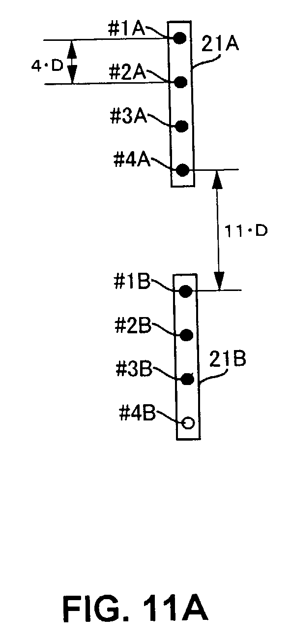
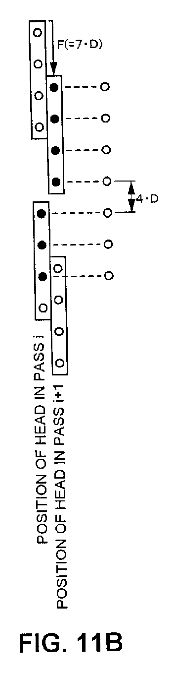
Fig. 11A is a diagram showing a configuration of a plurality
of nozzle groups, Fig. 11B is an explanatory diagram of a distance
between the nozzle groups, and Fig. 11C is an explanatory diagram of
printing using the plurality of nozzle groups.
Fig. 12A is a diagram showing a configuration of a plurality
of nozzle groups, Fig. 12B is an explanatory diagram of a distance
between the nozzle groups, and Fig. 12C is an explanatory diagram of
printing using the plurality of nozzle groups.
Fig. 13A is a diagram showing a configuration of a plurality
of nozzle groups, Fig. 13B is an explanatory diagram of a distance
between the nozzle groups, and Fig. 13C is an explanatory diagram of
printing using the plurality of nozzle groups.
Fig. 14A is a diagram showing a configuration of a plurality
of nozzle groups, Fig. 14B is an explanatory diagram of a distance
between the plurality of nozzle groups, and Fig. 14C is an explanatory
diagram of printing using the plurality of nozzle groups.
Fig. 15A is an explanatory diagram of a head used for two purposes,
Fig. 15B is an explanatory diagram of a distance between nozzles that
eject ink, and Fig. 15C is an explanatory diagram of printing when
the head is used for two purposes.
Fig. 16A is a diagram showing a configuration of a nozzle group
of a first example, and Fig. 16B is a diagram showing a configuration
of a head of the first example.
Fig. 17A is a diagram showing a configuration of a nozzle group
of a second example, and Fig. 17B is a diagram showing a configuration
of a head of the second example.
Fig. 18 is a diagram showing a configuration of a head of a third
example.
Fig. 19 is a diagram showing a configuration of a head of a fourth
example.
Fig. 20 is an explanatory diagram showing an external
configuration of a computer system.
Fig. 21 is a block diagram showing a configuration of the computer
system shown in Fig. 11.
Fig. 22 is an explanatory diagram showing a user interface.
Fig. 23 is an explanatory diagram of a format of print data.
<Regarding Reference Numerals>
10 paper carrying unit, 11A paper insert opening, 11B roll paper
insert opening, 13 paper supply roller, 14 platen, 15 paper feed motor
(PF motor), 16 paper feed motor driver (PF motor driver), 17A paper
feed roller, 17B paper discharge rollers, and 18A and 18B free rollers.
20 ink ejection unit, 21 head (21A to 21C, nozzle groups A to
C), and 22 head driver.
30 cleaning unit, 31 pump device, 32 pump motor, 33 pump motor
driver, and 35 capping device.
40 carriage unit, 41 carriage, 42 carriage motor (CR motor),
43 carriage motor driver (CR motor driver), 44 pulley, 45 timing belt,
and 46 guide rail.
50 measuring instrument group, 51 linear encoder, 511 linear
scale, 512 detection section, 52 rotary encoder, 53 paper detection
sensor, and 54 paper width sensor.
60 control unit, 61 CPU, 62 timer, 63 interface section, 64 ASIC,
65 memory, 66 DC controller, and 67 host computer.
Best Mode for Carrying Out the Invention
=== Overview of the Disclosure ===
At least the following matters will be made clear by the present
specification and the description of the accompanying drawings.
A recording apparatus for forming dots on a medium, comprises:
wherein the recording apparatus forms the dots on the medium
by repeating alternately an ejection operation in which a liquid is
ejected from the nozzles and a carry operation in which the medium
is carried using a predetermined carry amount with respect to the head;
and
wherein a distance between two nozzles that eject the liquid
adjacently and that belong to different ones of the nozzle groups is
equal to a sum of an integral multiple of the carry amount and the
predetermined nozzle pitch.
According to this recording apparatus, design flexibility can
be increased when a plurality of nozzle groups are provided in the
head.
In the recording apparatus, it is desirable that there is a nozzle
between the two nozzles that does not eject the liquid. According to
this recording apparatus, the distance between the two nozzles can
be set as appropriate without changing the configuration of the head.
In the recording apparatus, it is desirable that a nozzle at
one end of the plurality of nozzles that are arranged does not eject
the liquid. According to this recording apparatus, recording can be
performed such that the condition of the distance between the two
nozzles is satisfied without changing the configuration of the head.
Moreover, according to this recording apparatus, the number of nozzles
that eject the liquid is not limited to the number of nozzles contained
in the head. Therefore, the recording apparatus can be adopted even
for a recording mode in which the carry amount is set in accordance
with the number of nozzles that eject the liquid, without changing
the configuration of the head.
In the recording apparatus, it is desirable that the recording
apparatus is capable of performing recording using different recording
modes. This recording apparatus offers a high level of design
flexibility of the head, so that it is possible to use the same head
to perform recording using different recording modes. Moreover, it
is preferable that the nozzles that eject the liquid differ for
different ones of the recording modes. According to this recording
apparatus, the distance between the two nozzles can be set as
appropriate according to the recording mode. Moreover, it is
preferable that a spacing of the dots formed on the medium differs
for different ones of the recording modes. Since the carry amount
varies with the spacing of dots, the distance between the two nozzles
has to be matched with that carry amount. However, according to this
recording apparatus, the distance between the two nozzles can be set
as appropriate according to the carry amount, so that different dot
spacings can be formed using the same head. Furthermore, it is
preferable that a number of the nozzles that form a single raster line
differs for different ones of the recording modes. Since the carry
amount varies with the number of nozzles that form a single raster
line, the distance between the two nozzles has to be matched with that
carry amount. However, according to this recording apparatus, the
distance between the two nozzles can be set as appropriate according
to the carry amount, so that different dot spacings can be formed using
the same head. Furthermore, it is advantageous that the distance
between the two nozzles is equal to a sum of an even multiple of the
carry amount and the nozzle pitch. According to this recording
apparatus, it is possible to provide a head that can be used for a
plurality of print modes.
In the recording apparatus, it is desirable that the head
includes three or more of the nozzle groups; and a number of the nozzles
that eject the liquid is equal between at least two of the nozzle groups.
Moreover, it is preferable that the two nozzle groups are provided
adjacent to each other in a direction in which the medium is carried.
According to this recording apparatus, all of the distances between
the two nozzles can be set to be equal.
In the recording apparatus, it is desirable that when a spacing
of the dots formed on the medium is D, the nozzle pitch is k·D, a number
of the nozzles that are allowed to eject the liquid is N, and the carry
amount is F, then N and k are coprime, and F = N·D. According to this
recording apparatus, it is possible to perform interlaced printing
using the head provided with a plurality of nozzle groups.
In the recording apparatus, it is desirable that when a single
raster line is formed by M nozzles, and when a spacing of the dots
formed on the medium is D, the nozzle pitch is k·D, a number of the
nozzles that are allowed to eject the liquid is N, and the carry amount
is F, then N/M is an integer, N/M and k are coprime, and F = (N/M)·D.
According to this recording apparatus, it is possible to perform
overlap printing using the head provided with a plurality of nozzle
groups. Moreover, it is preferable that the distance between the two
nozzles is equal to a sum of an integral multiple of a value obtained
by multiplying the carry amount by M and the predetermined nozzle pitch.
According to this recording apparatus, it is possible to perform
recording using a mode other than overlap printing without changing
the configuration of the head.
A recording method using a head having a plurality of nozzle
groups, each of which has a plurality of nozzles that are arranged
with a predetermined nozzle pitch, is also possible. An ejection
operation in which a liquid is ejected from the nozzles and a carry
operation in which a medium is carried using a predetermined carry
amount with respect to the head are repeated alternately to form dots
on the medium, and the ejection operation is performed such that a
distance between two nozzles that eject the liquid adjacently and that
belong to different nozzle groups is equal to a sum of an integral
multiple of the carry amount and the predetermined nozzle pitch.
A storage medium for storing a program for controlling a
recording apparatus is also possible. The storage medium includes a
storage medium for storing the program, and the recording apparatus
includes a head having a plurality of nozzle groups, and each of the
nozzle groups has a plurality of nozzles that are arranged with a
predetermined nozzle pitch, and the program makes: (1) the recording
apparatus form dots on a medium by repeating alternately an ejection
operation in which a liquid is ejected from the nozzles and a carry
operation in which the medium is carried using a predetermined carry
amount with respect to the head; and (2) the recording apparatus perform
the ejection operation such that a distance between two nozzles that
eject the liquid adjacently and that belong to different nozzle groups
is equal to a sum of an integral multiple of the carry amount and the
predetermined nozzle pitch.
A computer system including a main computer unit and a recording
apparatus is also possible. The recording apparatus includes a head
having a plurality of nozzle groups, each nozzle group having a
plurality of nozzles that are arranged with a predetermined nozzle
pitch, and forms dots on a medium by repeating alternately an ejection
operation in which a liquid is ejected from the nozzles and a carry
operation in which the medium is carried using a predetermined carry
amount with respect to the head, and a distance between two nozzles
that eject the liquid adjacently and that belong to different nozzle
groups is equal to a sum of an integral multiple of the carry amount
and the predetermined nozzle pitch.
=== Overview of Printing Apparatus (Inkjet Printer) ===
<Regarding a Configuration of the Inkjet Printer>
An overview of an inkjet printer serving as an example of a
printing apparatus is described with reference to Figs. 1, 2, 3, and
4. Fig. 1 is an explanatory diagram of an overall configuration of
an inkjet printer of this embodiment. Fig. 2 is a schematic diagram
of a carriage area of the inkjet printer of this embodiment. Fig. 3
is an explanatory diagram of a carrying unit area of the inkjet printer
of this embodiment. Fig. 4 is a perspective view of the carrying unit
area of the inkjet printer of this embodiment.
The inkjet printer of this embodiment has a paper carrying unit
10, an ink ejection unit 20, a cleaning unit 30, a carriage unit 40,
a measuring instrument group 50, and a control unit 60.
The paper carrying unit 10 is for feeding paper, which is an
example of a medium to be printed, into a printable position and making
the paper move in a predetermined direction (the direction
perpendicular to the paper face in Fig. 1 (hereinafter, referred to
as the "paper carrying direction")) by a predetermined shift amount
during printing. In other words, the paper carrying unit 10 functions
as a carrying mechanism for carrying paper. The paper carrying unit
10 has a paper insert opening 11A and a roll paper insert opening 11B,
a paper supply motor (not shown), a paper supply roller 13, a platen
14, a paper feed motor (hereinafter, referred to as "PF motor") 15,
a paper feed motor driver (hereinafter, referred to as "PF motor
driver") 16, a paper feed roller 17A and paper discharge rollers 17B,
and free rollers 18A and free rollers 18B. However, the paper carrying
unit 10 does not necessarily have to include all of these components
in order to function as a carrying mechanism.
The paper insert opening 11A is where paper, which is a medium
to be printed, is inserted. The roll paper insert opening 11B is where
roll paper is inserted. The paper supply motor (not shown) is a motor
for carrying the paper that has been inserted into the paper insert
opening 11A into the printer, and is constituted by a pulse motor.
The paper supply roller 13 is a roller for automatically carrying the
paper that has been inserted into the paper insert opening 11 into
the printer, and is driven by the paper supply motor 12. The paper
supply roller 13 has a transverse cross-sectional shape that is
substantially the shape of the letter D. The peripheral length of a
circumference section of the paper supply roller 13 is set longer than
the carrying distance to the PF motor 15, so that using this
circumference section the medium to be printed can be carried up to
the PF motor 15. It should be noted that a plurality of media to be
printed are kept from being supplied at one time by the rotational
drive force of the paper supply roller 13 and the friction resistance
of separating pads (not shown). The sequence through which the medium
to be printed is carried is described in detail later.
The platen 14 supports the paper S during printing. The PF motor
15 is a motor for feeding paper, which is an example of a medium to
be printed, in the paper carrying direction, and is constituted by
a DC motor. The PF motor driver 16 is for driving the PF motor 15.
The paper feed roller 17A is a roller for feeding the paper S that
has been carried into the printer by the paper supply roller 13 to
a printable region, and is driven by the PF motor 15. The free rollers
18A are provided in a position that is in opposition to the paper feed
roller 17A, and push the paper S toward the paper feed roller 17A by
sandwiching the paper S between them and the paper feed roller 17A.
The paper discharge rollers 17B are rollers for discharging the
paper S for which printing has finished to outside the printer. The
paper discharge rollers 17B are driven by the PF motor 15 through a
gear that is not shown in the drawings. The free rollers 18B are
provided in a position that is in opposition to the paper discharge
rollers 17B, and push the paper S toward the paper discharge rollers
17B by sandwiching the paper S between them and the paper discharge
rollers 17B.
The ink ejection unit 20 is for ejecting ink onto paper, which
is an example of a medium to be printed. The ink ejection unit 20 has
a head 21 and a head driver 22. The head 21 has a plurality of nozzles
from which ink is ejected, and ejects ink intermittently from each
of the nozzles. The head driver 22 is for driving the head 21 so that
ink is ejected intermittently from the head.
The cleaning unit 30 is for preventing the nozzles of the head
21 from becoming clogged. The cleaning unit 30 has a pump device 31
and a capping device 35. The pump device is for extracting ink from
the nozzles in order to prevent the nozzles of the head 21 from becoming
clogged, and has a pump motor 32 and a pump motor driver 33. The pump
motor 32 sucks out ink from the nozzles of the head 21. The pump motor
driver 33 drives the pump motor 32. The capping device 35 is for sealing
the nozzles of the head 21 when printing is not being performed (during
standby) so that the nozzles of the head 21 are kept from becoming
clogged.
The carriage unit 40 is for making the head 21 scan and move
in a predetermined direction (the left to right direction of the paper
face in Fig. 1 (hereinafter, this is referred to as "scanning
direction")). The carriage unit 40 has a carriage 41, a carriage motor
(hereinafter, referred to as "CR motor") 42, a carriage motor driver
(hereinafter, referred to as "CR motor driver") 43, a pulley 44, a
timing belt 45, and a guide rail 46. The carriage 41 can be moved in
the scanning direction, and the head 21 is fastened to it (thus, the
nozzles of the head 21 intermittently eject ink as they are being moved
in the scanning direction). Moreover, the carriage 41 removably holds
an ink cartridge 48 that accommodates ink. The CR motor 42 is a motor
for moving the carriage in the scanning direction, and is constituted
by a DC motor. The CR motor driver 43 is for driving the CR motor 42.
The pulley 44 is attached to a rotation shaft of the CR motor 42. The
timing belt 45 is driven by the pulley 44. The guide rail 46 is for
guiding the carriage 41 in the scanning direction.
The measuring instrument group 50 includes a linear encoder 51,
a rotary encoder 52, a paper detection sensor 53, and a paper width
sensor 54. The linear encoder 51 is for detecting the position of the
carriage 41. The rotary encoder 52 is for detecting the amount of
rotation of the paper feed roller 17A. It should be noted that the
configuration, for example, of the encoders is discussed later. The
paper detection sensor 53 is for detecting the position of the front
end of the paper to be printed. The paper detection sensor 53 is
provided in a position where it can detect the position of the front
end of the paper as the paper is being carried toward the paper feed
roller 17A by the paper supply roller 13. It should be noted that the
paper detection sensor 53 is a mechanical sensor that detects the front
end of the paper through a mechanical mechanism. More specifically,
the paper detection sensor 53 has a lever that can be rotated in the
paper carrying direction, and this lever is disposed so that it
protrudes into the path along which the paper is carried. In this way,
the front end of the paper comes into contact with the lever and the
lever is rotated, and thus the paper detection sensor 53 detects the
position of the front end of the paper by detecting the movement of
the lever. The paper width sensor 54 is attached to the carriage 41.
The paper width sensor 54 is an optical sensor having a light emitting
section 541 and a light receiving section 543, and detects whether
the paper exists or not in the position of the paper width sensor 54
by detecting light that is reflected by the paper. The paper width
sensor 54 detects the position of the edge of the paper while being
moved by the carriage 41, so as to detect the width of the paper. The
paper width sensor 54 can detect the front end of the paper by the
position of the carriage 41. The paper width sensor 54 is an optical
sensor, and thus detects positions with higher precision than the paper
detection sensor 53.
The control unit 60 is for carrying out control of the printer.
The control unit 60 has a CPU 61, a timer 62, an interface section
63, an ASIC 64, a memory 65, and a DC controller 66. The CPU 61 is
for carrying out the overall control of the printer, and sends control
commands to the DC controller 66, the PF motor driver 16, the CR motor
driver 43, the pump motor driver 32, and the head driver 22. The timer
62 periodically generates interrupt signals with respect to the CPU
61. The interface section 63 exchanges data with a host computer 67
provided outside the printer. The ASIC 64 controls the printing
resolution and the drive waveforms of the head, for example, based
on printing information sent from the host computer 67 through the
interface section 63. The memory 65 is for reserving an area for
storing the programs for the ASIC 64 and the CPU 61 and a working area,
for example, and has a storage section such as a RAM or an EEPROM.
It should be noted that a program associated with printing operation
that is discussed later is stored in the memory 65. The DC controller
66 controls the PF motor driver 16 and the CR motor driver 43 based
on control commands sent from the CPU 61 and the output from the
measuring instrument group 50.
<Regarding the Configuration of the Encoders>
Fig. 5 is an explanatory diagram of the linear encoder 51.
The linear encoder 51 is for detecting the position of the
carriage 41, and has a linear scale 511 and a detection section 512.
The linear scale 511 has slits provided at a predetermined
spacing (for example, every 1/180 inches (1 inch = 2.54 cm)), and is
fastened to the main printer unit.
The detection section 512 is provided in opposition to the linear
scale 511, and is on the carriage 41 side. The detection section 512
has a light emitting diode 512A, a collimating lens 512B, and a
detection processing section 512C. The detection processing section
512C is provided with a plurality of (for example, four) photodiodes
512D, a signal processing circuit 512E, and two comparators 512Fa and
512Fb.
The light emitting diode 512A emits light when a voltage Vcc
is applied to it via resisters on both ends, and this light is incident
on the collimating lens. The collimating lens 512B turns the light
emitted from the light emitting diode 512A into parallel light, and
irradiates the linear scale 511 with the parallel light. The parallel
light that has passed through the slits provided in the linear scale
passes through stationary slits (not shown) and is incident on the
photodiodes 512D. The photodiodes 512D convert the incident light
into electrical signals. The electrical signals output from the
photodiodes are compared in the comparators 512Fa and 512Fb, and the
comparison results are output in the form of pulses. The pulse ENC-A
and the pulse ENC-B that are output from the comparators 512Fa and
512Fb are the output of the linear encoder 51.
Fig. 6A is a timing chart of waveforms of output signals when
the CR motor 42 is rotating forward. Fig. 6B is a timing chart of the
waveforms of the output signals when the CR motor 42 is rotating in
reverse.
As shown in Figs. 6A and 6B, the phases of the pulse ENC-A and
the pulse ENC-B are misaligned by 90 degrees both when the CR motor
42 is rotating forward and when it is rotating in reverse. When the
CR motor 42 is rotating forward, that is, when the carriage 41 is moving
in the main-scanning direction, the phase of the pulse ENC-A leads
the phase of the pulse ENC-B by 90 degrees, as shown in Fig. 6A. On
the other hand, when the CR motor 42 is rotating in reverse, the phase
of the pulse ENC-A is delayed by 90 degrees with respect to the phase
of the pulse ENC-B, as shown in Fig. 6B. A single period T of the pulses
is equal to the time during which the carriage 41 is moved by the spacing
of the slits of the linear scale 511 (for example, by 1/180 inches
(1 inch = 2.54 cm)).
The position of the carriage 41 is detected as follows. First,
the rising edge or the falling edge of either of the pulse ENC-A or
ENC-B is detected, and the number of detected edges is counted. The
position of the carriage 41 is calculated based on the counted number.
With respect to the count number, when the CR motor 42 is rotating
forward, a "+1" is added for each detected edge, and when the CR motor
42 is rotating in reverse, a "-1" is added for each detected edge.
Since the period of the pulses ENC is equivalent to the slit spacing
of the linear scale 511, when the counted number is multiplied by the
slit spacing, the amount that the carriage 41 has moved from when the
count number is "0" can be obtained. In other words, the resolution
of the linear encoder 51 in this case is the slit spacing of the linear
scale 511. It is also possible to detect the position of the carriage
41 using both of the pulse ENC-A and the pulse ENC-B. The periods of
the pulse ENC-A and the pulse ENC-B are equivalent to the slit spacing
of the linear scale 511, and the phases of the pulse ENC-A and the
pulse ENC-B are misaligned by 90 degrees, so that if the rising edges
and the falling edges of the pulses are detected and the number of
detected edges is counted, then a counted number "1" corresponds to
1/4 of the slit spacing of the linear scale 511. Therefore, if the
counted number is multiplied by 1/4 of the slit spacing, then the amount
that the carriage 41 has moved from when the count number was "0" can
be obtained. That is, the resolution of the linear encoder 51 in this
case is 1/4 of the slit spacing of the linear scale 511.
The velocity Vc of the carriage 41 is detected as follows. First,
the rising edges or the falling edges of either the pulse ENC-A or
ENC-B are detected. On the other hand, the time interval between edges
of the pulses is counted with a timer counter. The period T (T = T1,
T2, ...) is obtained from the counted value. Then, when the slit spacing
of the linear scale 511 is λ, the velocity of the carriage can be found
sequentially as λ/T. It is also possible to detect the velocity of
the carriage 41 using both of the pulse ENC-A and the pulse ENC-B.
By detecting the rising edges and the falling edges of the pulses,
the time interval between edges, which corresponds to 1/4 of the slit
spacing of the linear scale 511, is counted with the timer counter.
The period T (T = T1, T2, ...) is obtained from the counted value. Then,
when the slit spacing of the linear scale 511 is λ, the velocity Vc
of the carriage can be found sequentially as Vc = λ/(4T).
The rotary encoder 52 has substantially the same configuration
as the linear encoder 51, except that a rotation disk 521 that rotates
in accordance with rotation of the paper feed roller 17A is used in
place of the linear scale 511 that is provided on the main printer
unit side, and that a detection section 522 that is provided on the
main printer unit side is used in place of the detection section 512
that is provided on the carriage 41 (see Fig. 4).
It should be noted that the rotary encoder 52 directly detects
the rotation amount of the paper feed roller 17A, and does not detect
the carry amount of the paper. However, when the paper feed roller
17A is rotated to carry the paper, a carry error occurs due to slippage
between the paper feed roller 17A and the paper. Therefore, the rotary
encoder 52 cannot directly detect the carry error of the carry amount
of the paper. Accordingly, a table that expresses the relationship
between the rotation amount detected by the rotary encoder 52 and the
carry error is created and stored in the memory 65 of the control unit
60. Then, the table is referenced based on the results detected by
the rotary encoder, and the carry error is detected. This table is
not limited to expressing the relationship between the rotation amount
and the carry error, and also may be a table that expresses the
relationship between the number of times of carries, for example, and
the carry error. Moreover, because slippage varies depending on the
characteristics of the paper, it is also possible to create a plurality
of tables corresponding to the paper characteristics and to store these
tables in the memory 65.
<Regarding the Configuration of the Nozzles>
Fig. 7 is an explanatory diagram showing an arrangement of the
nozzles. A plurality of nozzle groups (nozzle group 21A and nozzle
group 21B) are provided on the lower surface of the head 21. Each nozzle
group includes a dark black ink nozzle row KD, a light black ink nozzle
row KL, a dark cyan ink nozzle row CD, a light cyan ink nozzle row
CL, a dark magenta ink nozzle row MD, a light magenta ink nozzle row
ML, and a yellow ink nozzle row YD. The nozzle rows are provided with
a plurality of (in this embodiment, n) nozzles from which ink for the
respective colors is ejected.
A plurality of nozzles of the nozzle groups are arranged at a
constant spacing (nozzle pitch: k·D) in the paper carrying direction.
Here, D is the minimum dot pitch in the paper carrying direction (that
is, the spacing at the highest resolution of the dots formed on the
paper S). Moreover, k is an integer of 1 or more.
The nozzles of the nozzle groups are assigned numbers that become
smaller toward the downstream side (#1 to #n). The paper width sensor
54 is provided slightly downstream of the nozzle #n that is on the
downstream side of the furthest downstream nozzle group in respect
to the paper carrying direction. Each nozzle is provided with a piezo
element (not shown) as a drive element for driving the nozzle and making
it eject ink droplets.
In this embodiment, the head 21 has a plurality of nozzle groups.
The arrangement of the plurality of nozzle groups is discussed in detail
later. However, in the description discussed later, the nozzle groups
are described having only a black ink nozzle row. This is for the sake
of simplifying the description by omitting the description of nozzle
rows for other colors because the manner in which dots are formed is
the same also in the cases of the nozzle rows for other colors. In
the diagram, the head 21 has two nozzle groups. However, it is
sufficient that the number of nozzle groups is more than one, and the
number is not limited to two.
During printing, the paper S is carried intermittently by the
paper carrying unit 10 using a predetermined carry amount, and between
these intermittent carries the carriage 41 is moved in the scanning
direction and ink droplets are ejected from the nozzles.
=== Examples for Reference ===
First, print modes in the case where a single nozzle group is
disposed along the carrying direction are described as examples for
reference.
<Regarding Interlaced Printing 1>
Figs. 8A and 8B are first explanatory diagrams of ordinary
interlaced printing. It should be noted that, for convenience sake,
the head (or the nozzle group) is illustrated as moving with respect
to the paper, but Figs. 8A and 8B diagrams show the relative positions
of the head and the paper, and in practice the paper is moved in the
carrying direction. Moreover, in Figs. 8A and 8B, a nozzle shown by
a solid circle is a nozzle that is allowed to eject ink, and a nozzle
shown by an open circle is a nozzle that is not allowed to eject ink.
Fig. 8A shows the positions of the head (or the nozzle group) and the
manner in which dots are formed in passes 1 to 4, and Fig. 8B shows
the positions of the head and the manner in which dots are formed in
passes 1 to 6.
Here, "interlaced mode" refers to a print mode in which k is
at least 2 and a raster line that is not recorded is sandwiched between
raster lines that are recorded in a single pass. Moreover, the "pass"
refers to a single scanning movement in which the nozzles are moved
and scan in the scanning direction. The "raster line" is a row of pixels
lined up in the scanning direction, and is also referred to as a "scan
line". Moreover, the "pixels" are square grids that are determined
in a virtual manner on the medium to be printed in order to define
the positions where ink droplets are made to land so as to record dots.
With interlaced printing, every time the paper is carried in
the carrying direction by a constant carry amount F, each nozzle records
a raster line immediately above the raster line that was recorded in
the previous pass. In order to perform recording while keeping the
carry amount constant in this manner, the number N (integer) of nozzles
that are allowed to eject ink and k are coprime, and the carry amount
F is set to N·D.
In Figs. 8A and 8B, the nozzle group has four nozzles arranged
in the carrying direction. However, since the nozzle pitch k of the
nozzle group is 4, not all the nozzles can be used so that the condition
for performing interlaced printing, that is, "N and k are coprime",
is satisfied. Therefore, three of the four nozzles are used to perform
interlaced printing. Moreover, since three nozzles are used, the
paper is carried using a carry amount of 3·D. As a result, for example,
dots are formed on the paper with a dot spacing of 720 dpi (= D) using
the nozzle group with a nozzle pitch of 180 dpi (4·D).
Figs. 8A and 8B show the manner in which continuous raster lines
are formed, with the first raster line being formed by the nozzle #1
in the pass 3, the second raster line being formed by the nozzle #2
in the pass 2, the third raster line being formed by the nozzle #3
in the pass 1, and the fourth raster line being formed by the nozzle
#1 in the pass 4. It should be noted that only the nozzle #3 ejects
ink in the pass 1 and only the nozzle #2 and the nozzle #3 eject ink
in the pass 2. The reason for this is that if ink is ejected from all
of the nozzles in the pass 1 and the pass 2, continuous raster lines
cannot be formed on the paper. In the pass 3 and thereafter, the three
nozzles (#1 to #3) eject ink and the paper is carried by a constant
carry amount F (= 3·D), and thus continuous raster lines are formed
with a dot spacing of D.
<Regarding Interlaced Printing 2>
Figs. 9A and 9B are second explanatory diagrams of ordinary
interlaced printing. As compared with the first explanatory diagrams
described above, the number of nozzles contained in the head (nozzle
group) is different. The nozzle pitch, for example, is the same as
in the case of the above-described explanatory diagrams, so that the
description thereof is omitted.
In Figs. 9A and 9B, the nozzle group has eight nozzles arranged
in the carrying direction. However, since the nozzle pitch k of the
nozzle group is 4, not all the nozzles can be used so that the condition
for performing interlaced printing, that is, "N and k are coprime",
is satisfied. Therefore, seven of the eight nozzles are used to perform
interlaced printing. Moreover, since seven nozzles are used, the
paper is carried using a carry amount of 7·D.
Figs. 9A and 9B show the manner in which continuous raster lines
are formed, with the first raster line being formed by the nozzle #2
in the pass 3, the second raster line being formed by the nozzle #4
in the pass 2, the third raster line being formed by the nozzle #6
in the pass 1, and the fourth raster line being formed by the nozzle
#1 in the pass 4. In the pass 3 and thereafter, the seven nozzles (#1
to #7) eject ink and the paper is carried using a constant carry amount
F (= 7·D), and thus continuous raster lines are formed with a dot spacing
of D.
As compared with the above-described interlaced printing, the
number of nozzles contained in the head (nozzle group) is increased.
Therefore, the number N of nozzles that are allowed to eject ink is
increased, so that the carry amount F during a single carry is increased,
and thus the printing speed is increased. In this manner, when
interlaced printing is performed, it is advantageous to increase the
number of nozzles that are allowed to eject ink because the printing
speed is increased.
<Regarding Overlap Printing>
Figs. 10A and 10B are explanatory diagrams of ordinary overlap
printing. In the above-described interlaced printing, a single raster
line is formed by a single nozzle. On the other hand, in overlap
printing, a single raster line is formed by two or more nozzles, for
example.
In overlap printing, every time the paper is carried in the
carrying direction by a constant carry amount F, each nozzle forms
dots intermittently every several dots. Then, another nozzle forms
dots in another pass so as to complement the intermittent dots that
have already been formed, and thus a single raster line is completed
by a plurality of nozzles. The overlap number M is defined as the number
of passes needed to complete a single raster line. In Figs. 10A and
10B, since each nozzle forms a dot intermittently every other dot,
a dot is formed every pass at the odd-numbered pixels or at the
even-numbered pixels. Since a single raster line is formed by two
nozzles, the overlap number M = 2. It should be noted that in the case
of the above-described interlaced printing, the overlap number M =
1.
In overlap printing, the conditions for performing recording
while keeping the carry amount constant are: (1) N/M is an integer;
(2) N/M and k are coprime; and (3) the carry amount F is set to (N/M)·D.
In Figs. 10A and 10B, the nozzle group has eight nozzles arranged
in the carrying direction. However, since the nozzle pitch k of the
nozzle group is 4, not all the nozzles can be used so that the condition
for performing overlap printing, that is, "N/M and k are coprime",
is satisfied. Therefore, six of the eight nozzles are used to perform
interlaced printing. Moreover, since six nozzles are used, the paper
is carried using a carry amount of 3·D. As a result, dots are formed
on the paper with a dot spacing of 720 dpi (= D) using the nozzle group
with a nozzle pitch of 180 dpi (4·D), for example. Furthermore, in
a single pass, each nozzle forms a dot intermittently every other dot
in the scanning direction. In the diagrams, raster lines for which
two dots are illustrated in the scanning direction have already been
completed. For example, in Fig. 10A, the first through the sixth raster
lines have already been completed. The raster lines for which one dot
is illustrated are raster lines in which a dot is formed intermittently
every other dot. For example, in the seventh and the tenth raster lines,
a dot is formed intermittently every other dot. It should be noted
that the seventh raster line, in which a dot is formed intermittently
every other dot, is completed when the nozzle #1 in the pass 9 forms
dots so as to complement the intermittent dots.
Figs. 10A and 10B show the manner in which continuous raster
lines are formed, with the first raster line being formed by the
nozzle
#4 in the
pass 3 and the
nozzle #1 in the
pass 7, the second raster
line being formed by the
nozzle #5 in the
pass 2 and the
nozzle #2
in the
pass 6, the third raster line being formed by the
nozzle #6
in the
pass 1 and the
nozzle #3 in the
pass 5, and the fourth raster
line being formed by the
nozzle #4 in the
pass 4 and the
nozzle #1
in the
pass 8. It should be noted that in the
passes 1 to 6, some of
the
nozzles #1 to #6 do not eject ink. The reason for this is that
if ink is ejected from all of the nozzles in the
passes 1 to 6, continuous
raster lines cannot be formed on the paper. In the
pass 7 and thereafter,
the six nozzles (#1 to #6) eject ink and the paper is carried using
a constant carry amount F (= 3·D), and thus continuous raster lines
are formed with a dot spacing of
D.
| | 1 | 2 | 3 | 4 | 5 | 6 | 7 | 8 |
| recorded pixels | odd | even | odd | even | even | odd | even | odd |
Table 1 is a table for describing the positions in the scanning
direction where dots are formed in each pass. In the table, "odd" means
that dots are formed at odd-numbered pixels of the pixels lined up
in the scanning direction (pixels in a raster line). Moreover, "even"
in the table means that dots are formed at even-numbered pixels of
the pixels lined up in the scanning direction. For example, in the
pass 3, the nozzles form dots at odd-numbered pixels. When a single
raster line is formed by M nozzles, k × M passes are required in order
to complete the raster lines corresponding to the amount of the nozzle
pitch. For example, in this embodiment, a single raster line is formed
by two nozzles, so that 8 (4 × 2) passes are required in order to complete
four raster lines. As can be seen from Table 1, in the four passes
during the first half, dots are formed in the order of odd-even-odd-even.
Consequently, when the four passes during the first half have finished,
dots are formed at even-numbered pixels in raster lines adjacent to
raster lines in which dots are formed at odd-numbered pixels. In the
four passes during the second half, dots are formed in the order of
even-odd-even-odd. In other words, in the four passes during the
second half, dots are formed in reverse order with respect to the four
passes during the first half. Consequently, dots are formed so as to
fill up gaps between the dots that have been formed in the passes during
the first half.
Also in overlap printing, when the number N of nozzles that are
allowed to eject ink is increased, the carry amount F during a single
carry is increased, and thus the printing speed is increased, as in
the above-described interlaced printing. Therefore, when overlap
printing is performed, it is advantageous to increase the number of
nozzles that are allowed to eject ink because the printing speed is
increased.
=== Printing Using a Plurality of Nozzle Groups (Simplified Models) ===
Next, printing using a plurality of nozzle groups of the present
embodiment is described. Various operations of the printer described
below are executed by the CPU 61 controlling the units based on a program
stored in the memory 65 within the printer. Moreover, this program
is constituted by codes for performing the various operations described
below. It should be noted that in the description below, the concepts
of the dot spacing (D), the nozzle pitch (k·D), the number (N) of nozzles
that are allowed to eject ink, the carry amount (F), and the overlap
number (M), for example, are the same as those in the above-described
examples for reference, so that the descriptions thereof are omitted.
<Interlaced Printing Using Two Nozzle Groups 1>
Fig. 11A is an explanatory diagram of a configuration of a
plurality of nozzle groups of this embodiment. Fig. 11B is an
explanatory diagram of the distance between the plurality of nozzle
groups of this embodiment. Fig. 11C is an explanatory diagram of
interlaced printing using the plurality of nozzle groups of this
embodiment.
A head in this embodiment is provided with two nozzle groups
(a first nozzle group 21A and a second nozzle group 21B). Each of the
first nozzle group 21A and the second nozzle group 21B has four nozzles.
The nozzle pitch in each nozzle group is 4·D (k = 4), as is the case
with the examples for reference described above.
The head of this embodiment is provided such that the distance
between the nozzle groups (more specifically, the distance between
the nozzle #4A of the first nozzle group 21A and the nozzle #1B of
the second nozzle group 21B) is 11·D. In other words, the head of this
embodiment is provided such that the distance between the nozzle groups
is equal to the sum of the carry amount (7·D) and the nozzle pitch
(4·D). Thus, dots that have been formed by the nozzles of the nozzle
group 21B in a given pass (pass i) and dots that have been formed by
the nozzles of the nozzle group 21A in the subsequent pass (pass i+1)
are formed continuously in the carrying direction with a spacing of
4·D.
That is, according to the head of this embodiment, by being
carried by a predetermined carry amount (7·D), the first nozzle group
21A in the pass i+1 and the second nozzle group 21B in the pass i function
in a pseudo manner as eight nozzles that are arranged with a nozzle
pitch of 4·D (see Fig. 11B).
In this embodiment, the two nozzle groups function in a pseudo
manner as eight nozzles that are arranged with a nozzle pitch 4·D,
so that when interlaced printing is performed, seven of the eight
nozzles are used (seven nozzles are allowed to eject ink), as described
in the examples for reference above. Furthermore, since seven nozzles
are used, the paper is carried using a carry amount of 7·D when
performing interlaced printing.
Fig. 11C shows the manner in which continuous raster lines are
formed, with the first raster line being formed by the nozzle #2A in
the pass 4, the second raster line being formed by the nozzle #4A in
the pass 3, the third raster line being formed by the nozzle #2B in
the pass 1, and the fourth raster line being formed by the nozzle #1
in the pass 5. It should be noted that in the passes 1 to 4, some nozzles
of the seven nozzles (nozzles #1A to #4A and nozzles #1B to #3B) that
are normally used do not eject ink. The reason for this is that if
ink is ejected from all of the nozzles in the passes 1 to 4, continuous
raster lines cannot be formed on the paper. In the pass 5 and thereafter,
the seven nozzles (nozzles #1A to #4A and nozzles #1B to #3B) eject
ink and the paper is carried using a constant carry amount F (= 7·D),
and thus continuous raster lines are formed with a dot spacing of D.
According to this embodiment, the number of nozzles that are
allowed to eject ink is increased relative to the interlaced printing
using four nozzles (example for reference), so that the printing speed
is advantageously increased.
Moreover, according to this embodiment, when compared to the
interlaced printing using one nozzle group having eight nozzles
(example for reference), it is possible to produce a head by separating
the nozzle group into two parts, so that design flexibility when
producing the head is improved. As a result, the head can be produced
inexpensively. In particular, the distance between the two nozzle
groups can be larger than the nozzle pitch (k·D), and thus design
flexibility when producing the head is improved.
<Interlaced Printing Using Two Nozzle Groups 2>
Fig. 12A is an explanatory diagram of a configuration of a
plurality of nozzle groups of this embodiment. Fig. 12B is an
explanatory diagram of the distance between the plurality of nozzle
groups of this embodiment. Fig. 12C is an explanatory diagram of
interlaced printing using the plurality of nozzle groups of this
embodiment. This embodiment as compared with the above-described
embodiment is different in the distance between the two nozzle groups.
Other aspects are substantially the same as in the above-described
embodiment, so that the description thereof is omitted.
A head of this embodiment is provided such that the distance
between the nozzle groups (more specifically, the distance between
the nozzle #4A of the first nozzle group 21A and the nozzle #1B of
the second nozzle group 21B) is 15·D. In other words, the head of this
embodiment is provided such that the distance between the nozzle groups
is equal to the sum of twice the carry amount (7·D) and the nozzle
pitch (4·D). Thus, dots that have been formed by the nozzles of the
nozzle group 21B in a given pass (pass i) and dots that have been formed
by the nozzles of the nozzle group 21A in the second next pass (pass
i+2) are formed continuously in the carrying direction with a spacing
of 4·D.
That is, according to the head of this embodiment, by being
carried by a predetermined carry amount (7·D × 2), the first nozzle
group 21A in the pass i+2 and the second nozzle group 21B in the pass
i function in a pseudo manner as eight nozzles that are arranged with
a nozzle pitch of 4·D (see Fig. 12B).
In this embodiment, the two nozzle groups function in a pseudo
manner as eight nozzles that are arranged with a nozzle pitch of 4·D,
so that when interlaced printing is performed, seven of the eight
nozzles are used (seven nozzles are allowed to eject ink), as described
in the examples for reference above. Furthermore, since seven nozzles
are used, the paper is carried using a carry amount of 7·D when
performing interlaced printing.
Fig. 12C shows the manner in which continuous raster lines are
formed, with the first raster line being formed by the nozzle #2A in
the pass 5, the second raster line being formed by the nozzle #4A in
the pass 4, the third raster line being formed by the nozzle #2B in
the pass 1, and the fourth raster line being formed by the nozzle #1
in the pass 6. It should be noted that in the passes 1 to 5, some nozzles
of the seven nozzles (nozzles #1A to #4A and nozzles #1B to #3B) that
are normally used do not eject ink. The reason for this is that if
ink is ejected from all of the nozzles in the passes 1 to 4, continuous
raster lines cannot be formed on the paper. In the pass 5 and thereafter,
the seven nozzles (nozzles #1A to #4A and nozzles #1B to #3B) eject
ink and the paper is carried using a constant carry amount F (= 7·D),
and thus continuous raster lines are formed with a dot spacing of D.
According to this embodiment, it is possible to achieve more
advantageous effects than in the examples for reference, as in the
case of the above-described embodiment.
As is apparent from both of this embodiment and the
above-described embodiment, the conditions for performing interlaced
printing satisfy the conditions of ordinary interlaced printing (see
examples for reference), and also include the condition that the
distance between the nozzle groups is (α × F) + (k·D) (α is an integer).
It should be noted that in the conditions for performing ordinary
interlaced printing, the nozzle pitch (k·D), the number (N) of nozzles
that are allowed to eject ink, and the carry amount (F) are closely
related to each other. In other words, the conditions for performing
ordinary interlaced printing are: (1) the number N (integer) of nozzles
that are allowed to eject ink and k are coprime; and (2) the carry
amount F is set to N·D.
<Interlaced Printing Using Three Nozzle Groups>
Fig. 13A is an explanatory diagram of a configuration of a
plurality of nozzle groups of this embodiment. Fig. 13B is an
explanatory diagram of the distance between heads of the plurality
of nozzle groups of this embodiment. Fig. 13C is an explanatory diagram
of interlaced printing using the plurality of nozzle groups of this
embodiment. This embodiment is different from the above-described
embodiments in the number of nozzle groups.
A head of this embodiment is provided with three nozzle groups
(a first nozzle group 21A, a second nozzle group 21B, and a third nozzle
group 21C). The nozzle groups each have four nozzles. The nozzle
pitch in the nozzle groups is 4·D (k = 4) as is the case with the examples
for reference discussed above.
The head of this embodiment is provided such that the distance
between the nozzle groups (more specifically, the distance between
the nozzle #4A of the first nozzle group 21A and the nozzle #1B of
the second nozzle group 21B, and the distance between the nozzle #4B
of the second nozzle group 21B and the nozzle #1C of the third nozzle
group 21C) is 11·D. In other words, the head of this embodiment is
provided such that the distance between the nozzle groups is equal
to the sum of the carry amount (11·D) and the nozzle pitch (4·D). Thus,
dots that have been formed by the nozzles of the nozzle group 21B in
a given pass (pass i) and dots that have been formed by the nozzles
of the nozzle group 21A in the subsequent pass (pass i+1) are formed
continuously in the carrying direction with a spacing of 4·D. Moreover,
thus, dots that have been formed by the nozzles of the nozzle group
21C in a given pass (pass i) and dots that have been formed by the
nozzles of the nozzle group 21B in the subsequent pass (pass i+1) are
formed continuously in the carrying direction with a spacing of 4·D.
That is, according to the head of this embodiment, by being
carried by a predetermined carry amount (11·D), the nozzle groups
function in a pseudo manner as twelve nozzles that are arranged with
a nozzle pitch of 4·D (see Fig. 12B).
In this embodiment, the three nozzle groups function in a pseudo
manner as twelve nozzles that are arranged with a nozzle pitch of 4·D,
so that when interlaced printing is performed, eleven of the twelve
nozzles are used (eleven nozzles are allowed to eject ink).
Furthermore, since eleven nozzles are used (N = 11), the paper is
carried using a carry amount of 11·D when performing interlaced
printing.
Fig. 13C shows the manner in which continuous raster lines are
formed, with the first raster line being formed by the nozzle #3A in
the pass 5, the second raster line being formed by the nozzle #2B in
the pass 3, the third raster line being formed by the nozzle #1C in
the pass 1, and the fourth raster line being formed by the nozzle #1A
in the pass 6. It should be noted that in the passes 1 to 5, some nozzles
of the eleven nozzles (nozzles #1A to #4A, nozzles #1B to #4B, and
nozzles #1C to #3C) that are normally used do not eject ink. The reason
for this is that if ink is ejected from all of the nozzles in the passes
1 to 5, continuous raster lines cannot be formed on the paper. In the
pass 5 and thereafter, the eleven nozzles (nozzles #1A to #4A, nozzles
#1B to #4B, and nozzles #1C to #3C) eject ink and the paper is carried
using a constant carry amount F (= 11·D), and thus continuous raster
lines are formed with a dot spacing of D.
According to this embodiment, it is possible to achieve more
advantageous effects than in the examples for reference, as is the
case in the above-described embodiments.
Moreover, according to this embodiment, the number of nozzle
groups is increased compared to the above-described embodiments, so
that the number of nozzles that are allowed to eject ink can be increased.
Therefore, this embodiment is advantageous because the number of
nozzles that are allowed to eject ink is increased and thus the printing
speed is increased.
It should be noted that according to this embodiment, the
distance between the nozzle groups was 11·D, but this is not a
limitation. Moreover, according to this embodiment, the distance
between the nozzle group 21A and the nozzle group 21B is equal to the
distance between the nozzle group 21B and the nozzle group 21C. However,
this is not a limitation. The point is that it is sufficient that each
distance between the nozzle groups satisfies (α × F) + (k·D) (α is
an integer).
According to this embodiment, the number of nozzles that are
allowed to eject ink of the first nozzle group 21A was equal to the
number of nozzles that are allowed to eject ink of the second nozzle
group 21B. In this manner, when interlaced printing is performed using
a head provided with three nozzle groups, it is desirable to set the
number of nozzles that are allowed to eject ink of two nozzle groups
to be equal to each other and to set the number of nozzles that are
allowed to eject ink of the other nozzle group such that the total
(N) of the number of nozzles that are allowed to eject ink satisfies
the conditions of interlaced printing.
<Overlap Printing Using Two Nozzle Groups>
Fig. 14A is an explanatory diagram of a configuration of a
plurality of nozzle groups of this embodiment. Fig. 14B is an
explanatory diagram of the distance between heads of the plurality
of nozzle groups of this embodiment. Fig. 11C is an explanatory diagram
of overlap printing using the plurality of nozzle groups of this
embodiment.
A head of this embodiment is provided with two nozzle groups
(a first nozzle group 21A and a second nozzle group 21B). Each of the
first nozzle group 21A and the second nozzle group 21B has four nozzles.
The nozzle pitch in each nozzle group is 4·D (k = 4), as is the case
with the examples for reference discussed above.
The head of this embodiment is provided such that the distance
between the nozzle groups (more specifically, the distance between
the nozzle #4A of the first nozzle group 21A and the nozzle #1B of
the second nozzle group 21B) is 7·D. In other words, the head of this
embodiment is provided such that the distance between the nozzle groups
is equal to the sum of the carry amount (3·D) and the nozzle pitch
(4·D). Thus, dots that have been formed by the nozzles of the nozzle
group 21B in a given pass (pass i) and dots that have been formed by
the nozzles of the nozzle group 21A in the subsequent pass (pass i+1)
are formed continuously in the carrying direction with a spacing of
4·D.
That is, according to the head of this embodiment, by being
carried by a predetermined carry amount (3·D), the first nozzle group
21A in the pass i+1 and the second nozzle group 21B in the pass i function
in a pseudo manner as eight nozzles that are arranged with a nozzle
pitch of 4·D (see Fig. 14B).
In this embodiment, the two nozzle groups function in a pseudo
manner as eight nozzles that are arranged with a nozzle pitch of 4·D,
so that when overlap printing is performed, six of the eight nozzles
are used (six nozzles are allowed to eject ink), as described in the
examples for reference above. Furthermore, since six nozzles are used
(N = 6), the paper is carried using a carry amount of 3·D (= (N/M)·D)
when performing overlap printing (provided M = 2).
Fig. 14C shows the manner in which continuous raster lines are
formed, with the first raster line being formed by the
nozzle #4A in
the
pass 4 and the
nozzle #1 in the
pass 8, the second raster line
being formed by the
nozzle #1B in the
pass 2 and the
nozzle #2A in
the
pass 7, the third raster line being formed by the
nozzle #2B in
the
pass 1 and the
nozzle #3A in the
pass 6, and the fourth raster
line being formed by the
nozzle #4A in the
pass 5 and the
nozzle #1A
in the
pass 9. It should be noted that in the
passes 1 to 7, some nozzles
of the six nozzles (
nozzles #1A to #4A and
nozzles #1B and #2B) that
are normally used do not eject ink. The reason for this is that if
ink is ejected from all of the nozzles in the
passes 1 to 7, continuous
raster lines cannot be formed on the paper. In the
pass 8 and thereafter,
the six nozzles (
nozzles #1A to #4A and
nozzles #1B and #2B) eject
ink and the paper is carried using a constant carry amount F (= 3·D),
and thus continuous raster lines are formed with a dot spacing of
D.
| | 1 | 2 | 3 | 4 | 5 | 6 | 7 | 8 |
| recorded pixels | nozzle group A | odd | odd | even | odd | even | even | odd | even |
| nozzle group B | odd | even | odd | even | even | odd | even | odd |
Table 2 is a table for describing the positions in the scanning
direction where dots are formed in each pass. Since the table is read
in the same manner as in the case of Table 2, the description thereof
is omitted. When a single raster line is formed by M nozzles, k × M
+ α passes are required in order to complete the raster lines
corresponding to the amount of the nozzle pitch. For example, in this
embodiment, a single raster line is formed by two nozzles, and α =
1, so that 9 (4 × 2 + 1) passes are required in order to complete four
raster lines. As can be seen from Table 2, the positions where dots
are formed in each pass of the second nozzle group are the same as
those in the case of Table 1. That is, the second nozzle group forms
dots in the order of odd-even-odd-even in four passes during the first
half, and forms dots in the order of even-odd-even-odd in four passes
during the second half. On the other hand, the order of the positions
where dots are formed in each pass of the first nozzle group is
misaligned by an amount corresponding to α passes with respect to the
order in the case of the second nozzle group. In this embodiment, since
α = 1, dots are formed in the order of odd-even-odd-even in the passes
2 to 5, and dots are formed in the order of even-odd-even-odd in the
passes 6 to 9 (pass 1). It should be noted that if α is a multiple
of k × M, then the positions where dots are formed of the first nozzle
group are the same with those of the second nozzle group, so that ink
can be ejected from the nozzles at the same timing between the nozzle
groups.
According to this embodiment, when compared to the overlap
printing using one nozzle group having eight nozzles (example for
reference), it is possible to produce a head by separating the nozzle
group into two parts, so that design flexibility when producing the
head is improved. As a result, the head can be produced inexpensively.
In particular, the distance between the two nozzle groups can be larger
than the nozzle pitch (k·D), and thus design flexibility when producing
the head is improved.
The conditions for performing overlap printing of this
embodiment satisfy the conditions of ordinary overlap printing (see
example for reference), and also include the condition that the
distance between the nozzle groups is (α × F) + (k·D) (α is an integer).
It should be noted that, in the conditions for performing ordinary
overlap printing, the nozzle pitch (k·D), the number (N) of nozzles
that are allowed to eject ink, and the carry amount (F) are closely
related to each other. That is, the conditions for performing ordinary
overlap printing are: (1) N/M is an integer; (2) N/M and k are coprime;
and (3) the carry amount F is set to (N/M)·D.
Moreover, according to this embodiment, overlap printing was
performed using two nozzle groups. However, this is not a limitation.
For example, overlap printing can be performed using three nozzle
groups or using more than three nozzle groups. Furthermore, when three
or more nozzle groups are used, the distances between the nozzle groups
do not have to be equal, and it is sufficient that each distance between
the nozzle groups satisfies (α × F) + (k·D) (α is an integer).
<Head Sharing >
According to the examples for reference (Figs. 9B and 10B)
discussed above, the same head could be used to perform both interlaced
printing and overlap printing. On the other hand, according to the
present embodiments described above, the distance between the nozzle
groups was defined by a predetermined condition, so that the head that
was used in the case of interlaced printing (for example, Fig. 11C)
was different from that in the case of overlap printing (for example,
Fig. 14C).
However, it is not practical to prepare different heads for
different print modes. Moreover, it is convenient for a user that
interlaced printing and overlap printing can be performed using the
same head.
Thus, in the following, a head that can be used in different
print modes is described.
Figs. 15A to 15C are explanatory diagrams of interlaced printing
using the head that was used in the embodiment of overlap printing
described above. When compared to the embodiment of Figs. 11A to 11C
described above, the distance between the nozzle groups is different,
and also the nozzles that are allowed to eject ink of the second nozzle
group 21B are different. For example, Fig. 15C for this embodiment
is different from Fig. 11C for the above-described embodiment in that
the third raster line is formed by the nozzle #3B in the pass 1 in
this embodiment.
The head of this embodiment is provided such that the distance
between the nozzle #4A of the first nozzle group 21A and the nozzle
#1B of the second nozzle group 21B is 7·D, as in the case of the head
that was used in the embodiment of overlap printing described above.
That is, in the head of this embodiment, the distance between the nozzle
#4A of the first nozzle group 21A and the nozzle #2B of the second
nozzle group 21B is 11·D. Therefore, in this embodiment, interlaced
printing is performed using the nozzle #1B of the second nozzle group
21B as the nozzle that is not allowed to eject ink and the nozzles
#1A to #4A of the first nozzle group 21A and the nozzles #2B to #4B
of the second nozzle group 21B as the nozzles that are allowed to eject
ink.
In this embodiment, the distance between two adjacent nozzles
that are allowed to eject ink and that belong to different nozzle groups
(the distance between the nozzle #4A of the first nozzle group 21A
and the nozzle #2B of the second nozzle group 21B) is equal to the
sum of the carry amount (7·D) and the nozzle pitch (4·D). Thus, dots
that have been formed by the nozzles of the nozzle group 21B in a given
pass (pass i) and dots that have been formed by the nozzles of the
nozzle group 21A in the subsequent pass (pass i+1) are formed
continuously in the carrying direction with a spacing of 4·D.
That is, according to the head of this embodiment, by being
carried by a predetermined carry amount (7·D), the nozzles (nozzles
#1A to #4A) that are allowed to eject ink of the first nozzle group
21A in the pass i+1 and the nozzles (nozzles #2B to #4B) that are allowed
to eject ink of the second nozzle group 21B in the pass i function
in a pseudo manner as eight nozzles that are arranged with a nozzle
pitch of 4·D (see Fig. 15B).
In this manner, according to interlaced printing of this
embodiment, interlaced printing can be performed using the head that
can be used for overlap printing described above. That is, interlaced
printing and overlap printing can be performed using the same head,
so that the user can select a plurality of print modes.
It should be noted that, according to this embodiment, the
distance between the two adjacent nozzles that are allowed to eject
ink and that belong to different nozzle groups (the nozzle #4A of the
first nozzle group 21A and the nozzle #2B of the second nozzle group
21B) is equal to the sum of the carry amount (7·D) and the nozzle pitch
(4·D) and is 11·D. However, this is not a limitation. The point is
that it is sufficient that the distance between two adjacent nozzles
that are allowed to eject ink and that belong to different nozzle groups
satisfies (α × F) + (k·D) (α is an integer).
Moreover, in interlaced printing of this embodiment, the nozzle
#1B, which belongs to the nozzle group 21B and is on the side close
to the nozzle group 21A, is used as the nozzle that is not allowed
to eject ink. That is, there is a nozzle that does not eject ink between
the two adjacent nozzles that are allowed to eject ink and that belong
to different nozzle groups. In such a manner, the distance between
the two nozzles that are allowed to eject ink can be adjusted in order
to adapt to two print modes using different carry amounts without
changing the configuration of the head.
Moreover, according to the head of this embodiment, two nozzle
groups were used to perform interlaced printing (and overlap printing).
However, this is not a limitation. For example, it is also possible
to use three nozzle groups. Furthermore, when three or more nozzle
groups are used, the distances between two adjacent nozzles that are
allowed to eject ink and that belong to different nozzle groups do
not have to be equal to each other, and it is sufficient that each
distance satisfies (α × F) + (k·D) (α is an integer).
It should be noted that when the head is used for a plurality
of print modes, it is desirable that, if a print mode in which the
overlap number is an even number, then α, which defines the distance
between the two nozzles (α × F) + (k·D), is an even number. In
particular, when the resolution in the plurality of print modes is
equal (when D in a plurality of print modes is the same), and when
the overlap number of the print modes is M1 and M2 and α in the print
modes is α1 and α2, it is preferable that M1:M2 = α1:α2. The reason
for this is that although the carry amount F in each of the print modes
varies depending on the overlap number, a head with such a distance
is easily used for a plurality of print modes.
=== Printing Using a Plurality of Nozzle Groups (Practical Examples) ===
The above-described embodiments are simplified models in which
a single nozzle group is provided with only four nozzles. However,
the number of nozzles of a nozzle group that is used for a device in
practice is much larger than that of the above-described models so
that the printing speed is increased. This is described below using
a configuration of a practical nozzle group. However, the nozzle group
of the simplified models described above and the practical nozzle group
described below are based on the same idea of the present invention.
It should be noted that various operations of the printer that
are described below are executed by the CPU 61 controlling the units
based on a program stored in the memory 65 within the printer. Moreover,
this program is constituted by codes for performing the various
operations described below.
<Practical Example 1>
Fig. 16A is an explanatory diagram of a configuration of a nozzle
group that is used for the first example. Fig. 16B is an explanatory
diagram of a configuration of a head that is used for the first example.
In this example, each nozzle group is provided with two nozzle
rows. Each nozzle row has 180 nozzles, and the nozzle pitch is 180
dpi. Moreover, the two nozzle rows are arranged along the carrying
direction such that they are misaligned by an amount of 180 dpi.
Therefore, the nozzles in each nozzle group are arranged in a staggered
manner. By arranging the nozzles in this manner, the nozzle groups
of this example are provided with 360 nozzles and have a nozzle pitch
that is substantially 360 dpi. Three nozzle groups are arranged in
the carrying direction such that the distance between the nozzles #1
of the nozzle groups is 5 inches.
With the above-described head of this example, it is possible
to perform "overlap printing at 720 dpi × 720 dpi" and "band printing
at 360 dpi × 360 dpi". "Band printing" refers to a print mode in which
the nozzle pitch is equal to the dot spacing D (k = 1) and continuous
raster lines are formed in a single pass.
When "overlap printing at 720 dpi × 720 dpi" is performed, 327
nozzles, the nozzles #7 to #333, of the 360 nozzles of each of the
nozzle group 21A and the nozzle group 21B serve as the nozzles that
are allowed to eject ink. Moreover, 328 nozzles, the nozzles #7 to
334, of the 360 nozzles of the nozzle group 21C serve as the nozzles
that are allowed to eject ink. Accordingly, a total of 982 nozzles
serve as the nozzles that are allowed to eject ink. Furthermore, the
distance between two adjacent nozzles that are allowed to eject ink
and that belong to different nozzle groups (the distance between the
nozzle #333 of the nozzle group 21A and the nozzle #7 of the nozzle
group 21B and the distance between the nozzle #333 of the nozzle group
21B and the nozzle #7 of the nozzle group 21C) is 2948·D (note that
D = 1/720 inches). It should be noted that since printing is performed
at 720 dpi, the nozzle pitch is 2·D (k = 2). Moreover, the overlap
number M = 2, the carry amount F = 491·D, and α = 6.
When "band printing at 360 dpi × 360 dpi" is performed, 274
nozzles, the nozzles #43 to #316, of the 360 nozzles of each of the
nozzle group 21A and the nozzle group 21B serve as the nozzles that
are allowed to eject ink. Moreover, 271 nozzles, the nozzles #43 to
313, of the 360 nozzles of the nozzle group 21C serve as the nozzles
that are allowed to eject ink. Accordingly, a total of 819 nozzles
serve as the nozzles that are allowed to eject ink. Furthermore, the
distance between two adjacent nozzles that are allowed to eject ink
and that belong to different nozzle groups (the distance between the
nozzle #316 of the nozzle group 21A and the nozzle #43 of the nozzle
group 21B and the distance between the nozzle #316 of the nozzle group
21B and the nozzle #43 of the nozzle group 21C) is 1639·D (note that
D = 1/360 inches). It should be noted that since printing is performed
at 360 dpi, the nozzle pitch is 1·D (k = 1). Moreover, the overlap
number M = 1, the carry amount F = 819·D, and α = 2.
Also in this example, the same effects as those in the
above-described embodiments can be achieved.
Moreover, according to this example, liquid is ejected from part
of a plurality of nozzles contained in each of the nozzle groups. Thus,
the number of nozzles that are allowed to eject ink can be set without
being limited to the number of nozzles provided in the head.
Moreover, according to this example, nozzles that are arranged
at the ends of the nozzle groups do not eject ink. Thus, the number
of nozzles that are allowed to eject ink can be set as appropriate
according to the print mode without changing the configuration of the
head.
Moreover, according to this example, there are nozzles that do
not eject ink between two adjacent nozzles that are allowed to eject
ink and that belong to different nozzle groups. Thus, by suitably
setting the nozzles that are not allowed to eject ink, the distance
between two adjacent nozzles that are allowed to eject ink and that
belong to different nozzle groups can be adjusted according to the
print mode without changing the configuration of the head.
Furthermore, according to this example, the nozzles that are
used for overlap printing are different from the nozzles that are used
for band printing. In this manner, in this example, the nozzles that
eject ink differ for different recording modes.
Furthermore, according to this example, the head is designed
such that α is an even number during overlap printing at a resolution
of 720 dpi. Thus, it is possible to perform printing at 360 dpi, which
is half of that resolution, using the same head. It should be noted
that when the dot spacing D (D = 1/720 inches for 720 dpi) is D1 and
D2 in the respective print modes and α is α1 and α2 in the respective
print modes, it is preferable that 1/D1:1/D2 = α1:α2. This is because
a head with such a distance is easily used for a plurality of modes.
When a head is used for print modes with different resolutions, it
is desirable that α is an even number because the resolution of one
mode is often an even multiple of the resolution of the other mode.
Furthermore, according to this example, there are three nozzle
groups. Further, the number of nozzles that are allowed to eject ink
of the nozzle group 21A and the number of nozzles that are allowed
to eject ink of the nozzle group 21B that is adjacent to the nozzle
group 21A are set so as to be equal to each other.
Furthermore, according to this example, the head is designed
such that α during overlap printing is an integral multiple of the
overlap number M. Thus, the same head can be used to perform a plurality
of print modes.
<Practical Example 2>
Fig. 17A is an explanatory diagram of a configuration of a nozzle
group that is used for the second example. Fig. 17B is an explanatory
diagram of a configuration of a head that is used for the second example.
In this example, each nozzle group is provided with two nozzle
rows. Each nozzle row has 180 nozzles, and the nozzle pitch is 180
dpi. Moreover, the two nozzle rows are arranged along the carrying
direction such that they are misaligned by 177/180 inches. Further,
three nozzles at an end of each of the nozzle rows are not used (thus,
only 174 nozzles of each of the nozzle rows are used). Therefore, the
nozzles within each of the nozzle groups have substantially 348 (174
× 2) nozzles with a nozzle pitch of 180 dpi. Three nozzle groups are
arranged in the carrying direction such that the distance between the
nozzles #1 of the nozzle groups is 7.28 inches.
With the above-described head of this example, it is possible
to perform "overlap printing at 720 dpi × 720 dpi" and "interlaced
printing at 360 dpi × 360 dpi" (however, this is interlaced printing
in which k = 2).
When "overlap printing at 720 dpi × 720 dpi" is performed, 328
nozzles, the nozzles #1 to #328, of the 348 nozzles of each of the
nozzle group 21A and the nozzle group 21B serve as the nozzles that
are allowed to eject ink. Moreover, 326 nozzles, the nozzles #1 to
326, of the 348 nozzles of the nozzle group 21C serve as the nozzles
that are allowed to eject ink. Accordingly, a total of 982 nozzles
serve as the nozzles that are allowed to eject ink. Furthermore, the
distance between two adjacent nozzles that are allowed to eject ink
and that belong to different nozzle groups (the distance between the
nozzle #328 of the nozzle group 21A and the nozzle #1 of the nozzle
group 21B and the distance between the nozzle #328 of the nozzle group
21B and the nozzle #1 of the nozzle group 21C) is 3932·D (note that
D = 1/720 inches). It should be noted that since printing is performed
at 720 dpi, the nozzle pitch is 4·D (k = 4). Moreover, the overlap
number M = 2, the carry amount F = 491·D, and α = 8.
When "interlaced printing at 360 dpi × 360 dpi" is performed,
327 nozzles, the nozzles #1 to #327, of the 348 nozzles of each of
the nozzle group 21A and the nozzle group 21B serve as the nozzles
that are allowed to eject ink. Moreover, 329 nozzles, the nozzles #1
to 329, of the 348 nozzles of the nozzle group 21C serve as the nozzles
that are allowed to eject ink. Accordingly, a total of 983 nozzles
serve as the nozzles that are allowed to eject ink. Furthermore, the
distance between two adjacent nozzles that are allowed to eject ink
and that belong to different nozzle groups (the distance between the
nozzle #327 of the nozzle group 21A and the nozzle #1 of the nozzle
group 21B and the distance between the nozzle #327 of the nozzle group
21B and the nozzle #1 of the nozzle group 21C) is 1968·D (note that
D = 1/360 inches). It should be noted that since printing is performed
at 360 dpi, the nozzle pitch is 2·D (k = 2). Moreover, the overlap
number M = 1, the carry amount F = 983·D, and α = 2.
Also in this example, the same effects as those in the embodiments
and example described above can be achieved.
<Practical Example 3>
Fig. 18 is an explanatory diagram of a configuration of a head
that is used for the third example. It should be noted that the
configuration of the nozzle group that is used for this example is
the same as the configuration of the nozzle group of Example 2 described
above (see Fig. 17A), so that the description thereof is omitted. This
example is different from Example 2 described above in the distance
between nozzle groups. Regarding the nozzle groups, three nozzle
groups are arranged in the carrying direction such that the distance
between the nozzles #1 of the nozzle groups is 6.275 inches.
With the above-described head of this example, it is possible
to perform "overlap printing at 720 dpi × 720 dpi" and "interlaced
printing at 360 dpi × 360 dpi" (however, this is interlaced printing
in which k = 2).
When "overlap printing at 720 dpi × 720 dpi" is performed, all
of the 348 nozzles of each of the nozzle groups serve as the nozzles
that are allowed to eject ink. Accordingly, a total of 1042 nozzles
serve as the nozzles that are allowed to eject ink. Furthermore, the
distance between two adjacent nozzles that are allowed to eject ink
and that belong to different nozzle groups (the distance between the
nozzle #348 of the nozzle group 21A and the nozzle #1 of the nozzle
group 21B and the distance between the nozzle #348 of the nozzle group
21B and the nozzle #1 of the nozzle group 21C) is 3130·D (note that
D = 1/720 inches). It should be noted that since printing is performed
at 720 dpi, the nozzle pitch is 4·D (k = 4). Moreover, the overlap
number M = 2, the carry amount F = 521·D, and α = 6.
When "interlaced printing at 360 dpi × 360 dpi" is performed,
207 nozzles, the nozzles #1 to #207, of the 348 nozzles of each of
the nozzle group 21A and the nozzle group 21B serve as the nozzles
that are allowed to eject ink. Moreover, 201 nozzles, the nozzles #1
to 201, of the 348 nozzles of the nozzle group 21C serve as the nozzles
that are allowed to eject ink. Accordingly, a total of 615 nozzles
serve as the nozzles that are allowed to eject ink. Furthermore, the
distance between two adjacent nozzles that are allowed to eject ink
and that belong to different nozzle groups (the distance between the
nozzle #207 of the nozzle group 21A and the nozzle #1 of the nozzle
group 21B and the distance between the nozzle #207 of the nozzle group
21B and the nozzle #1 of the nozzle group 21C) is 1847·D (note that
D = 1/360 inches). It should be noted that since printing is performed
at 360 dpi, the nozzle pitch is 2·D (k = 2). Moreover, the overlap
number M = 1, the carry amount F = 615·D, and α = 3.
Also in this example, the same effects as those in the embodiments
and examples described above can be achieved.
<Practical Example 4>
Fig. 19 is an explanatory diagram of a configuration of a head
that is used for the fourth example. It should be noted that the
configuration of the nozzle group that is used for this example is
the same as the configuration of the nozzle group of Example 2 described
above (see Fig. 17A), so that the description thereof is omitted. This
example is different from Example 2 described above in the number of
nozzle groups and the distance between the nozzle groups. Regarding
the nozzle groups, five nozzle groups are arranged in the carrying
direction such that the distance between the nozzles #1 of the nozzle
groups is 11.53 inches.
With the above-described head of this example, it is possible
to perform "overlap printing at 720 dpi × 720 dpi" and "interlaced
printing at 360 dpi × 360 dpi" (however, this is interlaced printing
in which k = 2).
When "overlap printing at 720 dpi × 720 dpi" is performed, 346
nozzles, the nozzles #1 to #346, of the 348 nozzles of each of the
nozzle groups serve as the nozzles that are allowed to eject ink.
Accordingly, a total of 1730 nozzles serve as the nozzles that are
allowed to eject ink. Furthermore, the distance between two adjacent
nozzles that are allowed to eject ink and that belong to different
nozzle groups (for example, the distance between the nozzle #346 of
the nozzle group 21A and the nozzle #1 of the nozzle group 21B) is
6924·D (note that D = 1/720 inches). It should be noted that since
printing is performed at 720 dpi, the nozzle pitch is 4·D (k = 4).
Moreover, the overlap number M = 2, the carry amount F = 865·D, and
α = 8.
When "interlaced printing at 360 dpi × 360 dpi" is performed,
347 nozzles, the nozzles #1 to #347, of the 348 nozzles of each of
the nozzle groups 21A to 21D serve as the nozzles that are allowed
to eject ink. Moreover, 341 nozzles, the nozzles #1 to 341, of the
348 nozzles of the nozzle group 21E serve as the nozzles that are allowed
to eject ink. Accordingly, a total of 1729 nozzles serve as the nozzles
that are allowed to eject ink. Furthermore, the distance between two
adjacent nozzles that are allowed to eject ink and that belong to
different nozzle groups (for example, the distance between the nozzle
#347 of the nozzle group 21A and the nozzle #1 of the nozzle group
21B) is 3460·D (note that D = 1/360 inches). It should be noted that
since printing is performed at 360 dpi, the nozzle pitch is 2·D (k
= 2). Moreover, the overlap number M = 1, the carry amount F = 1729·D,
and α = 3.
Also in this example, the same effects as those in the embodiments
and examples described above can be achieved.
=== Configuration of the Computer System etc. ===
Next, an embodiment of a computer system, a computer program,
and a storage medium storing the computer program is described with
reference to the drawings.
Fig. 20 is an explanatory diagram showing an external
configuration of a computer system. A computer system 1000 is provided
with a main computer unit 1102, a display device 1104, a printer 1106,
an input device 1108, and a reading device 1110. In this embodiment,
the main computer unit 1102 is accommodated within a mini-tower type
housing. However, this is not a limitation. Generally, a CRT (Cathode
Ray Tube), plasma display, or liquid crystal display device, for
example, is used as the display device 1104, but there is no limitation
to this. The printer 1106 is the printer described above. In this
embodiment, the input device 1108 is a keyboard 1108A and a mouse 1108B,
but there is no limitation thereto. In this embodiment, a flexible
disk drive device 1110A and a CD-ROM drive device 1110B are used as
the reading device 1110, but there is no limitation thereto, and the
reading device 1110 can also be an MO (Magneto Optical) disk drive
device or a DVD (Digital Versatile Disk), for example.
Fig. 21 is a block diagram showing a configuration of the computer
system shown in Fig. 20. An internal memory 1202, such as a RAM, is
provided in the housing accommodating the main computer unit 1102,
and also an external memory, such as a hard disk drive unit 1204, is
provided.
A computer program for controlling the operation of the
above-described printer can be downloaded onto the computer system
1000, for example, connected to the printer 1106 via a communication
line, such as the Internet, and it can also be stored on a
computer-readable storage medium and distributed, for example.
Various types of storage media can be used as this storage medium,
including flexible disks FDs, CD-ROMs, DVD-ROMs, magneto optical disks
MOs, hard disks, and memories. It should be noted that information
stored on such storage media can be read out by various types of reading
devices 1110.
Fig. 22 is an explanatory diagram showing a user interface of
a printer driver that is displayed on a screen of the display device
1104 connected to the computer system. A user can use the input device
1108 to make various settings of the printer driver.
The user can select the print mode from this screen. For example,
the user can select as the print mode, a quick print mode or a fine
print mode. From this screen, the user also can select the dot spacing
(resolution) when printing. For example, from this screen, the user
can select 720 dpi or 360 dpi as the print resolution.
Fig. 23 is an explanatory diagram of a format of print data
supplied from the main computer unit 1102 to the printer 1106. The
print data is created from image information based on the settings
of the printer driver. The print data has a print condition command
group and command groups for respective passes. The print condition
command group includes a command for indicating the print resolution
and a command for indicating the print direction
(unidirection/bidirection), for example. The print command groups
for respective pass include a target carry amount command CL and a
pixel data command CP. The pixel data command CP includes pixel data
PD indicating the recording status for each pixel of the dots recorded
in that pass. It should be noted that the various commands shown in
the diagram each have a header section and a data section; however,
they are shown simplified. Moreover, these command groups are
supplied intermittently to the printer side from the main computer
unit side for each command. However, the print data is not limited
to this format.
In the above description, an example was described in which the
computer system is constituted by connecting the printer 1106 to the
main computer unit 1102, the display device 1104, the input device
1108, and the reading device 1110. However, this is not a limitation.
For example, the computer system can be made of the main computer unit
1102 and the printer 1106, or the computer system does not have to
be provided with any one of the display device 1104, the input device
1108, and the reading device 1110. It is also possible for the printer
1106 to have some of the functions or mechanisms of the main computer
unit 1102, the display device 1104, the input device 1108, and the
reading device 1110. For example, the printer 1106 can be configured
so as to have an image processing section for carrying out image
processing, a display section for carrying out various types of
displays, and a recording media attachment/detachment section to and
from which recording media storing image data captured by a digital
camera or the like are inserted and taken out.
In the embodiment described above, it is also possible for the
computer program for controlling the printer to be incorporated in
the memory 65, which is a storage medium, of the control unit 60. Also,
the control unit 60 can execute the computer program stored in the
memory 65 so as to achieve the operations of the printer in the
embodiment described above.
As an overall system, the computer system that is thus achieved
is superior to conventional systems.
=== Other Embodiments ===
In the foregoing description, the printer was mainly discussed.
However, it goes without saying that the foregoing description also
includes the disclosure of printing apparatuses, printing methods,
programs, storage media, computer systems, display screens, screen
display methods, methods for manufacturing printed material,
recording apparatuses, and devices for ejecting liquids, for example.
Moreover, a printer, for example, serving as an example was
described. However, the foregoing embodiments are for the purpose of
elucidating the present invention and is not to be interpreted as
limiting the present invention. The present invention can of course
be altered and improved without departing from the gist thereof and
includes functional equivalents.
<Regarding the Head>
In the embodiments and examples described above, the number of
nozzles was specified. However, the number of nozzles contained in
a single nozzle group is not limited to this.
Also, in the embodiments and examples described above, the number
of nozzle groups provided in the head was specified. However, the
number of nozzle groups provided in the head is not limited to this.
Also, in the embodiments and examples described above, the
nozzles that are allowed to eject ink were specified. However, the
nozzles that are allowed to eject ink are not limited to this.
Also, in the embodiments and examples described above, the print
mode was specified. However, the print mode is not limited to this.
<Regarding the Recording Apparatus>
In the embodiments and examples described above, a printer was
described as an example of recording apparatus. However, this is not
a limitation. For example, technology like that of the present
embodiments can also be adopted for various types of recording
apparatuses that use inkjet technology, including color filter
manufacturing devices, dyeing devices, fine processing devices,
semiconductor manufacturing devices, surface processing devices,
three-dimensional shape forming devices, liquid vaporizing devices,
organic EL manufacturing devices (in particular, macromolecular EL
manufacturing devices), display manufacturing devices, film formation
devices, and DNA chip manufacturing devices. Moreover, methods and
manufacturing methods of these are also within the scope of application.
Even when the present technology is adopted in these fields, the fact
that liquid can be directly ejected (written) onto a target object
enables achievement of a reduction in material, process steps, and
costs compared to conventional cases.
<Regarding the Ink>
Since the embodiments and examples described above were
discussed using a printer, a dye ink or a pigment ink was ejected from
the nozzles. However, the liquid that is ejected from the nozzles is
not limited to such inks. For example, it is also possible to eject
from the nozzles a liquid (including water), such as metallic material,
organic material (in particular, macromolecular material), magnetic
material, conductive material, wiring material, film-formation
material, electronic ink, processed liquid, and genetic solutions.
If such liquids are directly ejected toward a target object, a reduction
in material, process steps, and costs can be achieved.
<Regarding the Nozzles>
In the embodiments and examples described above, ink was ejected
using piezoelectric elements. However, the method for ejecting liquid
is not limited to this. For example, other methods, such as a method
for generating bubbles in the nozzles by heat, can also be employed.
Industrial Applicability
According to the present invention, there is flexibility in
setting of the distance between the nozzle groups when a plurality
of nozzle groups are provided in the head. Moreover, the same head
can be adopted for a plurality of recording modes.