EP1604811A2 - Manufacturing method of tire reinforcing material and manufacturing method of pneumatic tire using the tire reinforcing material - Google Patents
Manufacturing method of tire reinforcing material and manufacturing method of pneumatic tire using the tire reinforcing material Download PDFInfo
- Publication number
- EP1604811A2 EP1604811A2 EP05004159A EP05004159A EP1604811A2 EP 1604811 A2 EP1604811 A2 EP 1604811A2 EP 05004159 A EP05004159 A EP 05004159A EP 05004159 A EP05004159 A EP 05004159A EP 1604811 A2 EP1604811 A2 EP 1604811A2
- Authority
- EP
- European Patent Office
- Prior art keywords
- ply
- tire
- joint
- cord fabric
- cords
- Prior art date
- Legal status (The legal status is an assumption and is not a legal conclusion. Google has not performed a legal analysis and makes no representation as to the accuracy of the status listed.)
- Granted
Links
Images


Classifications
-
- B—PERFORMING OPERATIONS; TRANSPORTING
- B29—WORKING OF PLASTICS; WORKING OF SUBSTANCES IN A PLASTIC STATE IN GENERAL
- B29D—PRODUCING PARTICULAR ARTICLES FROM PLASTICS OR FROM SUBSTANCES IN A PLASTIC STATE
- B29D30/00—Producing pneumatic or solid tyres or parts thereof
- B29D30/06—Pneumatic tyres or parts thereof (e.g. produced by casting, moulding, compression moulding, injection moulding, centrifugal casting)
- B29D30/38—Textile inserts, e.g. cord or canvas layers, for tyres; Treatment of inserts prior to building the tyre
-
- B—PERFORMING OPERATIONS; TRANSPORTING
- B29—WORKING OF PLASTICS; WORKING OF SUBSTANCES IN A PLASTIC STATE IN GENERAL
- B29D—PRODUCING PARTICULAR ARTICLES FROM PLASTICS OR FROM SUBSTANCES IN A PLASTIC STATE
- B29D30/00—Producing pneumatic or solid tyres or parts thereof
- B29D30/06—Pneumatic tyres or parts thereof (e.g. produced by casting, moulding, compression moulding, injection moulding, centrifugal casting)
- B29D30/38—Textile inserts, e.g. cord or canvas layers, for tyres; Treatment of inserts prior to building the tyre
- B29D30/42—Endless textile bands without bead-rings
-
- B—PERFORMING OPERATIONS; TRANSPORTING
- B29—WORKING OF PLASTICS; WORKING OF SUBSTANCES IN A PLASTIC STATE IN GENERAL
- B29D—PRODUCING PARTICULAR ARTICLES FROM PLASTICS OR FROM SUBSTANCES IN A PLASTIC STATE
- B29D30/00—Producing pneumatic or solid tyres or parts thereof
- B29D30/06—Pneumatic tyres or parts thereof (e.g. produced by casting, moulding, compression moulding, injection moulding, centrifugal casting)
- B29D30/38—Textile inserts, e.g. cord or canvas layers, for tyres; Treatment of inserts prior to building the tyre
- B29D30/42—Endless textile bands without bead-rings
- B29D2030/421—General aspects of the joining methods and devices for creating the bands
- B29D2030/423—Joining by overlapping
-
- Y—GENERAL TAGGING OF NEW TECHNOLOGICAL DEVELOPMENTS; GENERAL TAGGING OF CROSS-SECTIONAL TECHNOLOGIES SPANNING OVER SEVERAL SECTIONS OF THE IPC; TECHNICAL SUBJECTS COVERED BY FORMER USPC CROSS-REFERENCE ART COLLECTIONS [XRACs] AND DIGESTS
- Y10—TECHNICAL SUBJECTS COVERED BY FORMER USPC
- Y10S—TECHNICAL SUBJECTS COVERED BY FORMER USPC CROSS-REFERENCE ART COLLECTIONS [XRACs] AND DIGESTS
- Y10S156/00—Adhesive bonding and miscellaneous chemical manufacture
- Y10S156/906—Off-drum manufacture of tire fabric or ply
-
- Y—GENERAL TAGGING OF NEW TECHNOLOGICAL DEVELOPMENTS; GENERAL TAGGING OF CROSS-SECTIONAL TECHNOLOGIES SPANNING OVER SEVERAL SECTIONS OF THE IPC; TECHNICAL SUBJECTS COVERED BY FORMER USPC CROSS-REFERENCE ART COLLECTIONS [XRACs] AND DIGESTS
- Y10—TECHNICAL SUBJECTS COVERED BY FORMER USPC
- Y10T—TECHNICAL SUBJECTS COVERED BY FORMER US CLASSIFICATION
- Y10T156/00—Adhesive bonding and miscellaneous chemical manufacture
- Y10T156/10—Methods of surface bonding and/or assembly therefor
- Y10T156/1052—Methods of surface bonding and/or assembly therefor with cutting, punching, tearing or severing
- Y10T156/1062—Prior to assembly
- Y10T156/1066—Cutting to shape joining edge surfaces only
-
- Y—GENERAL TAGGING OF NEW TECHNOLOGICAL DEVELOPMENTS; GENERAL TAGGING OF CROSS-SECTIONAL TECHNOLOGIES SPANNING OVER SEVERAL SECTIONS OF THE IPC; TECHNICAL SUBJECTS COVERED BY FORMER USPC CROSS-REFERENCE ART COLLECTIONS [XRACs] AND DIGESTS
- Y10—TECHNICAL SUBJECTS COVERED BY FORMER USPC
- Y10T—TECHNICAL SUBJECTS COVERED BY FORMER US CLASSIFICATION
- Y10T156/00—Adhesive bonding and miscellaneous chemical manufacture
- Y10T156/10—Methods of surface bonding and/or assembly therefor
- Y10T156/1052—Methods of surface bonding and/or assembly therefor with cutting, punching, tearing or severing
- Y10T156/1062—Prior to assembly
- Y10T156/1075—Prior to assembly of plural laminae from single stock and assembling to each other or to additional lamina
- Y10T156/1079—Joining of cut laminae end-to-end
Definitions
- the present invention relates to a method of manufacturing a tire reinforcing material using a cord fabric as well as a method of manufacturing a pneumatic tire using the tire reinforcing material, particularly improving uniformity of joint regions at opposing ply ends of a reinforcing material used for such parts as tire carcass, chafer and bead reinforcing layer, and enhancing dynamic uniformity of the pneumatic tire in running.
- a cord fabric is generally used for a reinforcing material of a tire.
- a carcass ply of a radial tire has a cord fabric whose warp cords are arranged in the direction orthogonal to the circumference of the tire.
- a pneumatic tire of this radial construction is generally manufactured through the following processes.
- a rubber-coated ply is produced from the cord fabric constructed of a number of warp cords arranged in parallel with each other and wefts arranged for preventing the warp cords from separating.
- the ply is cut along the direction substantially orthogonal to the longitudinal direction of the warp cords into ply pieces each having a predetermined length.
- the ply pieces are joined together by laying each of the opposing ends along the longitudinal direction of the warp cords of a ply piece on one of the opposing ends of another ply piece so that a selvage including two to ten cords of one ply piece are joined onto a selvage including two to ten cords of another ply piece.
- the joining is repeated a plurality of times to form a cylindrical carcass ply.
- the carcass ply is thereafter combined with such reinforcing materials as bead cores and shaped into a toroid. Further, over the outer circumference of the toroidal carcass, a belt layer, a tread rubber and a sidewall rubber for example are applied and, through a subsequent vulcanization and shaping process, a pneumatic tire is produced.
- the ply pieces of the carcass ply are joined together for example as schematically shown in Fig. 4.
- respective opposing ends 41J, 42J of ply pieces 41, 42 are butt-joined to form a joint J.
- the warp cords at respective ends 41J, 42J of ply pieces 41, 42 have wavy outlines formed at respective folded-back portions 43 a of wefts 43. This is because the warp cords at the opposing ends of the cord fabric are restrained inwardly by the folded-back portions of the wefts. Therefore, at the joint of the ply pieces, the waviness of warp cords 40 still remains, deteriorating uniformity of the ply.
- ply pieces 51, 52 of a carcass ply may be joined together by laying opposing ends on each other to form a joint 5J.
- warp cords 51 a of ply piece 51 and warp cords 52a of ply piece 52 that are located at joint 5J overlap each other.
- joint 5J of the ply pieces contains a larger number of cords as compared with other portions of the ply, resulting in a smaller tension and a larger thermal shrinkage per cord as well as a larger stiffness of the joint.
- the joint expands less than other portions of the ply and consequently depressions of sidewalls are caused at the joint locations, resulting in a non-uniform shape of the sidewalls and considerable deterioration of uniformity in running.
- Japanese Utility Model Publication No. 4-14462 proposes to reduce the stiffness at the joint by using a special extension cord as a warp cord at a selvage (end) of a cord fabric.
- Japanese Patent Laying-Open No. 58-101805 discloses that low-shrinkage polyester cords are used at a selvage of a cord fabric.
- Japanese Patent Publication No. 61-43457 discloses a cord fabric having its selvage where high extension warp cords and normal warp cords are alternately arranged.
- the aforementioned inventions or the like each make improvements in the warp of the cord fabric.
- the weft of the cord fabric may be improved by providing the weft extending to be turned at the endmost warp cord at a selvage of the cord fabric and ending at the other selvage of the cord fabric, and the weft is V-shaped for stabilizing the movement of the warp.
- the present invention is a method of manufacturing a tire reinforcing material formed of a cord fabric constructed of warp cords arranged in parallel with each other and wefts arranged substantially orthogonally to the warp cords.
- the method includes: a topping step for coating with rubber the cord fabric having the wefts folded back at respective warp cords at opposing ends of the cord fabric to produce a ply; a cutting step for cutting the ply into ply pieces each having a predetermined length; a joint forming step for removing one to five cords at each of opposing ends of the ply to form a joint; and a joining step for joining together the joint of one of the ply pieces and the joint of another ply piece.
- the joint forming step In the joint forming step, one to five warp cords at each of the opposing ends of the ply is/are removed and a folded-back portion of the wefts at each of the opposing ends of the ply is cut. Thus, tension concentration in this region is avoided and the waviness at the joint is reduced.
- the joint is 0.5 to 2 mm in width.
- the tire reinforcing material is suitably used for a carcass ply. Further, the present invention is a method of manufacturing a pneumatic tire including the method of manufacturing the carcass ply.
- the warp cords located at the folded-back portions of the wefts of the cord fabric are restrained inwardly of the fabric, one to five of the warp cords is/are removed from the ply to form joints and the joints are laid on each other for joining together ply pieces, so that the ply of uniform property as that of portions of the ply except for the joints can be produced. Accordingly, when the tire having been shaped and vulcanized is filled with air to an appropriate internal pressure, reduction in occurrence of depressions of the sidewalls and improvements in uniformity can be achieved.
- the present invention is a method of manufacturing a tire reinforcing material formed of a cord fabric constructed of warp cords arranged in parallel with each other and wefts arranged substantially orthogonally to the warp cords.
- the method includes: a topping step for coating with rubber the cord fabric having the wefts folded back at respective warp cords at opposing ends of the cord fabric to produce a ply; a cutting step for cutting the ply into ply pieces each having a predetermined length; a joint forming step for removing one to five cords at each of opposing ends of the ply to form a joint; and a joining step for joining together the joint of one of the ply pieces and the joint of another ply piece.
- a cord fabric 3 is constructed of warp cords for reinforcing a tire that are interlaced with wefts, as described above.
- warp cords generally employed tire cords for example are used.
- the warp cords are not melted by heat during a vulcanizing and shaping process nor heat during a heating process for the purpose of adhesive application for example, and the warp cords are aligned in a vulcanized pneumatic tire to reinforce the pneumatic tire.
- warp cords 4 are arranged more densely than wefts 5. The density may arbitrarily be set depending on a tire to be used.
- warp cords 4 tire cords of polyethylene terephtalate, nylon, rayon, vinylon (particularly high-strength vinylon) or aramid may preferably be employed.
- the warp cords having a fineness in the range from 1260 denier to 6000 denier are preferably used and the wefts having a fineness of 180 denier to 270 denier may preferably be used.
- Wefts 5 extend substantially orthogonally to the longitudinal direction of warp cords 4, and wefts 5 as shown in Fig. 1A are interlaced with warp cords 4 so that the wefts alternately pass over and under every adjacent warp cords. Wefts 5 thus serve to keep the constant pitch of many warp cords 4 arranged on a plane. Wefts 5 may be interlaced as shown in Fig. 1A with opposing ends discontinued. Alternatively, wefts 5 may be interlaced to continuously extend and turn at right and left selvages. One of various interweaving methods may thus be employed.
- any yam of a material that has substantially no melting point and thus is resistant to heat like cotton and flat rayon, may be used.
- a low-melting-point material having a melting point of 110 to 150°C may also be used.
- wefts 5 are melted by the actions of heat and tension in a tire vulcanization process, and so-called straw-matting phenomenon, namely a phenomenon of making warp cords 4 wavy, can be prevented.
- the restraining force exerted on the warp cords by the wefts having a melting point in the range of 110 to 150°C can be weakened in the vulcanization process.
- any of high-density polyethylene, copolymer of vinyl chloride and vinyl acetate, copolymer of ethylene and vinyl acetate, polyamide terpolymer, polyamide quaterpolymer, and polyamide multipolymer, for example, may be used.
- Wefts 5 are interlaced for keeping constant intervals between the warp cords and preventing the warp cords from separating from each other. Wefts 5 are folded back at warp cords 4a at respective ends of cord fabric 3. Thus, warp cords 4a at folded-back portions 5a of the wefts are restrained inwardly of the cord fabric and accordingly likely to have a wavy shape.
- a ply refers to a cord fabric undergoing an adhesive application process and embedded in a rubber compound.
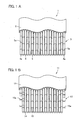
- Fig. 1A schematically shows a ply used for the present invention.
- a ply 1 has a rubber compound 2 in which a cord fabric 3 is embedded.
- the cord fabric has warp cords 4 arranged in parallel with the longitudinal direction and wefts 5 spaced at constant intervals in the longitudinal direction and arranged substantially orthogonally to the warp cords.
- the density of the warp cords in the ply is set to the range from 30 cords/5 cm to 50 cords/5 cm.
- the density of the wefts in the ply is set to the range from 2 wefts/5 cm to 6 wefts/5 cm.
- the cord fabric is subjected to the adhesive application process before embedded in the rubber compound.
- the adhesive application process includes an immersion process for immersing the cord fabric in an adhesive solution and a subsequent heating process for heating (baking) the cord fabric in the state in which a certain tension is exerted on the warp cords. Adhesiveness of the cord fabric for tire reinforcement to rubber is thus increased. After the adhesive application process, an unvulcanized rubber is applied over the top and bottom of the cord fabric. The so-called ply is thus prepared for use as a tire reinforcing material.
- the adhesive application process includes the immersion process in which the cord fabric for tire reinforcement is immersed in an adhesive solution containing for example a mixture of a primary condensation product of resorcin and formalin and vinylpyridine latex or a mixture of vinylpyridine latex and SBR latex to which various chemicals are added, and the subsequent heating process in which the cord fabric is heated in the state in which a certain tension is exerted on the warp cords.
- ply 1 is schematically shown having cord fabric 3 topped with unvulcanized rubber compound 2.
- Ply 1 is cut into ply pieces at constant intervals in the direction substantially orthogonal to the longitudinal direction of warp cords 4, namely cut in the direction that is substantially the same as that in which wefts 5 are arranged.
- the width of the cut side of the resultant ply piece corresponds to the arc length in the toroidal cross section of the carcass extending between beads and thus warp cords 4 are arranged at a right angle (in the radial direction) to the circumferential direction of the tire.
- FIG. 2A an end 21J of a ply piece 21 is laid on an end 22J of a ply piece 22.
- Fig. 2B Before the ply pieces are joined together, one to five warp cord/cords at each of ends 21J located at opposing ends of ply piece 21 and ends 22J located at opposing ends of ply piece 22 is/are removed.
- the traces of the removed warp cords at the ends of the ply pieces are indicated by 21 a, 22a.
- warp cords 4a at respective ends of the cord fabric are restrained inwardly of the cord fabric at the position of folded back portions 5a of wefts 5. Consequently, as shown in Fig. 4, warp cords 40 at the ends of the ply extend wavily in the longitudinal direction.
- the waviness at the joint of the ply pieces is eliminated by removing one to five warp cords at each end of the ply pieces.
- the number of the warp cords removed from the ply piece is one to three. When the number of removed warp cords is more than five, useless material cost is necessary for removing the cords while the waviness elimination effect is achieved.
- the width of the joint between ply pieces is preferably set to 0.5 to 2 mm
- a ply piece are joined by laying ends on each other so that the warp cords at the ends do not overlap and accordingly a single layer in which the warp cords are arranged at constant intervals in cross section is formed as shown in Fig. 2B.
- FIG. 3 shows a cross section of the right half of a pneumatic tire T, having, as a carcass ply 31, one ply extending from a tread 32 through a sidewall 33 to be turned and secured around a bead core 35 of a bead 34.
- a belt layer 36 of two plies is provided at an angle of 5° to 45° to the circumferential direction of the tire.
- the tire shown in Fig. 3 is a pneumatic tire of radial construction and the warp cords of the carcass ply are arranged to extend in the radial direction (orthogonal to the circumferential direction of the tire) in the tire.
- Pneumatic tire T is manufactured using this carcass ply through a usual shaping method. Specifically, the carcass ply, bead cores, the belt layer, and a tread rubber for example are assembled into a green tire cover that is vulcanized in a vulcanizing mold to produce the pneumatic tire.
- the cord fabric underwent an adhesive application process for improving adhesiveness to rubber.
- the cord fabric was immersed in an adhesive solution containing for example a mixture of a primary condensation product of resorcin and formalin, vinylpyridine latex and SBR latex to which various chemicals are added, and the cord fabric was heated in the state in which a certain tension was exerted on the warp cords.
- the top and bottom of the cord fabric were thereafter topped with an unvulcanized rubber and thus prepared as a ply to manufacture a tire reinforcing material.
- the ply was cut at constant intervals in the longitudinal direction. Since the ply was used as a carcass ply of a radial tire, the width of the cut side was made equal to the arc length in a cross section of a toroidal carcass extending between beads.
- Example 1 ply pieces into which the ply was cut were joined in the following way.
- the ply of the cord fabric shown in Fig. 1B was used.
- end 21J of ply piece 21 and end 22J of ply piece 22 were arranged to overlap each other.
- one warp cord at each of ends 21J located at opposing ends of ply piece 21 and ends 22J located at opposing ends of ply piece 22 was removed and wefts at folded-back portions 15a were cut.
- Comparative Example 1 a conventional ply from which no warp cord was removed was used. Table 1 shows specifications of the examples together with results of evaluation thereof.
- ply pieces are joined by laying ends on each other so that the warp cords at the ends do not overlap and accordingly a single layer in which the warp cords are arranged at constant intervals in cross section is formed as shown in Fig. 2B.
- a plurality of above-described ply pieces were joined into a cylindrical ply and this ply was applied to a carcass ply of a pneumatic radial tire with the size 195/65R15.
- the radial tire was manufactured as the pneumatic tire shown in Fig. 3.
- the specifications of the pneumatic radial tire are as follows.
- Belt layer two belt layers
- Steel cord 1 ⁇ 4 ⁇ 0.25
- Angle 22° ⁇ 22° (with respect to the tire circumferential direction)
- Tire vulcanizing conditions 165°C ⁇ 20 minutes
- RFV refers to vibrations in the up-and-down direction appearing on the axis of the tire when the tire is being rotated while a load is exerted thereon and the axis is kept at a certain level, the vibrations being a source of vibrations when a vehicle is actually running.
- the measurements were taken with a tire running machine under the conditions of a running speed of 60 rpm, a load of 4000 N and a rim width of 15 ⁇ 6 inches.
- the unit of the measurements is N.
- RV 1H represents the value of the primary component obtained by analyzing the measurement of RFV (OA) into components of order.
- RV 2H represents the value of the secondary component obtained by analyzing the measurement of RFV (OA) into components of order.
- a bulge/dent evaluation was made by visual inspection of unevenness of the outer surface of sidewalls of a tire. The result of the evaluation is indicated by score 1 to 5. A higher score represents a smaller degree of unevenness of the outer surface of the sidewalls. From Table 1, it is seen that the uniformity (RFV) as well as bulge/dent property of Example 1 are improved.
- Example 1 Comparative Example 1 cord fabric warp material polyester polyester denier 1500 1500 weft material cotton and polyester cotton and polyester denier 225 225 ply density of warp cords (number of cords/5 cm) 50 50 joint width (mm) 1.5 1.5 number of removed warp cords one at each end - tire tire properties uniformity (1) RFV ⁇ OA (N) 48.5 68.1 (2) RFV ⁇ 1H (N) 41.3 56.8 (3) RFV ⁇ 2H (N) 10.2 21.8 bulge/dent 3.8 3.2
- a pneumatic tire using a carcass ply manufactured by the method of manufacturing a tire reinforcing material of the present invention has no waviness nor overlap at the joint of the ply.
- the tire thus has uniformity as a whole.
- the tire is aesthetically pleasant and thus has a higher commercial value.
- the tire is also improved in uniformity (radial force variation) in running.
Landscapes
- Engineering & Computer Science (AREA)
- Textile Engineering (AREA)
- Mechanical Engineering (AREA)
- Tires In General (AREA)
- Tyre Moulding (AREA)
Abstract
Description
Belt layer: two belt layers
Steel cord: 1 × 4 × 0.25
Angle: 22° × 22° (with respect to the tire circumferential direction)
Tire vulcanizing conditions: 165°C × 20 minutes
| Example 1 | Comparative Example 1 | |||
| cord fabric | warp | material | polyester | polyester |
| denier | 1500 | 1500 | ||
| weft | material | cotton and polyester | cotton and polyester | |
| denier | 225 | 225 | ||
| ply | density of warp cords (number of cords/5 cm) | 50 | 50 | |
| joint width (mm) | 1.5 | 1.5 | ||
| number of removed warp cords | one at each end | - | ||
| tire tire properties | uniformity | |||
| (1) | RFV · OA (N) | 48.5 | 68.1 | |
| (2) | RFV · 1H (N) | 41.3 | 56.8 | |
| (3) | RFV · 2H (N) | 10.2 | 21.8 | |
| bulge/dent | 3.8 | 3.2 |
Claims (5)
- A method of manufacturing a tire reinforcing material formed of a cord fabric (3) constructed of warp cords (4) arranged in parallel with each other and wefts (5) arranged substantially orthogonally to said warp cords (4), comprising:a topping step for coating with rubber said cord fabric (3) having said wefts (5) folded back at respective warp cords (4a) at opposing ends of said cord fabric (3) to produce a ply (1);a cutting step for cutting said ply (1) into ply pieces each having a predetermined length;a joint forming step for removing one to five cords at each of opposing ends of said ply (1) to form a joint; anda joining step for joining together the joint of one of said ply pieces and the joint of another ply piece.
- The method of manufacturing a tire reinforcing material according to claim 1, wherein
in said joint forming step, one to five warp cords at each of the opposing ends of said ply (1) is/are removed and a folded-back portion of said wefts at each of the opposing ends of said ply (1) is cut. - The method of manufacturing a tire reinforcing material according to claim 1, wherein
said joint is 0.5 to 2 mm in width. - The method of manufacturing a tire reinforcing material according to claim 1, wherein
said tire reinforcing material is a carcass ply. - A method of manufacturing a pneumatic tire including the method of manufacturing the carcass ply as recited in claim 4.
Applications Claiming Priority (4)
| Application Number | Priority Date | Filing Date | Title |
|---|---|---|---|
| JP2004168749 | 2004-06-07 | ||
| JP2004168749 | 2004-06-07 | ||
| JP2004271426A JP3967348B2 (en) | 2004-06-07 | 2004-09-17 | Manufacturing method of tire reinforcing material and manufacturing method of pneumatic tire using the same |
| JP2004271426 | 2004-09-17 |
Publications (3)
| Publication Number | Publication Date |
|---|---|
| EP1604811A2 true EP1604811A2 (en) | 2005-12-14 |
| EP1604811A3 EP1604811A3 (en) | 2006-06-07 |
| EP1604811B1 EP1604811B1 (en) | 2007-11-14 |
Family
ID=34933941
Family Applications (1)
| Application Number | Title | Priority Date | Filing Date |
|---|---|---|---|
| EP05004159A Expired - Lifetime EP1604811B1 (en) | 2004-06-07 | 2005-02-25 | Manufacturing method of tire reinforcing material and manufacturing method of pneumatic tire using the tire reinforcing material |
Country Status (4)
| Country | Link |
|---|---|
| US (1) | US7314533B2 (en) |
| EP (1) | EP1604811B1 (en) |
| JP (1) | JP3967348B2 (en) |
| DE (1) | DE602005003262T2 (en) |
Families Citing this family (12)
| Publication number | Priority date | Publication date | Assignee | Title |
|---|---|---|---|---|
| CA2517822C (en) * | 2004-09-06 | 2009-10-27 | Honda Motor Co., Ltd. | Seat mount structure for saddle ride vehicle |
| US7669625B2 (en) | 2006-11-22 | 2010-03-02 | The Goodyear Tire & Rubber Company | Asymmetrical pneumatic tire |
| KR100888136B1 (en) | 2007-09-21 | 2009-03-13 | 금호타이어 주식회사 | Pneumatic Tire Manufacturing Method |
| US8776851B2 (en) | 2008-08-29 | 2014-07-15 | The Goodyear Tire & Rubber Company | Film to keep tire surface clean and simultaneously prime for better adhesion of balance pad |
| JP2010150368A (en) * | 2008-12-25 | 2010-07-08 | Toray Ind Inc | Fiber-reinforced plastic |
| JP5801779B2 (en) * | 2012-09-18 | 2015-10-28 | 住友ゴム工業株式会社 | Tire cord ply joining apparatus and joining method |
| JP6596819B2 (en) * | 2014-12-11 | 2019-10-30 | 住友ゴム工業株式会社 | Tire fabric for tire reinforcement and pneumatic tire using the same |
| BR102016017671A2 (en) * | 2015-08-31 | 2017-03-07 | Goodyear Tire & Rubber | tire canvas joint configuration |
| JP6723513B2 (en) * | 2016-03-18 | 2020-07-15 | 住友ゴム工業株式会社 | Corded rubber material manufacturing apparatus, corded rubber material manufacturing method, corded rubber material and pneumatic tire manufacturing method |
| US11084328B2 (en) * | 2018-11-29 | 2021-08-10 | The Goodyear Tire & Rubber Company | Tire reinforcement |
| CN111746015A (en) * | 2020-06-11 | 2020-10-09 | 江阴市澳星电气有限公司 | Production method of high-quality cord fabric |
| CN118650889B (en) * | 2024-08-20 | 2024-12-13 | 杭州数通超声光电有限公司 | Ultrasonic rapid welding process for butt-jointing after cutting tire fiber cord fabric |
Family Cites Families (10)
| Publication number | Priority date | Publication date | Assignee | Title |
|---|---|---|---|---|
| US1467289A (en) * | 1920-07-17 | 1923-09-04 | George M Eames | Method of fabricating tire fabrics |
| US2754887A (en) * | 1953-12-24 | 1956-07-17 | Firestone Tire & Rubber Co | Method of making a tubeless tire |
| US3237673A (en) * | 1961-06-05 | 1966-03-01 | Goodyear Tire & Rubber | Tubeless tire and method of splicing the inside plies of same |
| JPS56154532A (en) | 1980-04-24 | 1981-11-30 | Sumitomo Rubber Ind | Rubber reinforcing tire fabric |
| JPS58101805A (en) | 1981-12-09 | 1983-06-17 | Toyo Tire & Rubber Co Ltd | Radial structure type pneumatic tire |
| DE3312785C2 (en) * | 1983-04-09 | 1987-04-30 | Continental Gummi-Werke Ag, 3000 Hannover | Pneumatic vehicle tires with reinforcement inserts made of cord fabric |
| JPH0414462Y2 (en) | 1986-04-11 | 1992-03-31 | ||
| JPH05154938A (en) * | 1991-12-03 | 1993-06-22 | Yokohama Rubber Co Ltd:The | Manufacture of pneumatic radial tire |
| JP2000006262A (en) * | 1998-06-19 | 2000-01-11 | Bridgestone Corp | Rubber-coated thread ply jointed body and manufacture thereof |
| TW539629B (en) * | 2001-07-31 | 2003-07-01 | Sumitomo Rubber Ind | Tire-use rubber-covered fabric, its production method, the production method for pneumatic tire using rubber-covered fabric, and pneumatic tire |
-
2004
- 2004-09-17 JP JP2004271426A patent/JP3967348B2/en not_active Expired - Fee Related
-
2005
- 2005-02-25 DE DE602005003262T patent/DE602005003262T2/en not_active Expired - Lifetime
- 2005-02-25 EP EP05004159A patent/EP1604811B1/en not_active Expired - Lifetime
- 2005-03-01 US US11/067,740 patent/US7314533B2/en not_active Expired - Fee Related
Also Published As
| Publication number | Publication date |
|---|---|
| DE602005003262D1 (en) | 2007-12-27 |
| US7314533B2 (en) | 2008-01-01 |
| JP2006021514A (en) | 2006-01-26 |
| JP3967348B2 (en) | 2007-08-29 |
| EP1604811A3 (en) | 2006-06-07 |
| EP1604811B1 (en) | 2007-11-14 |
| US20050269015A1 (en) | 2005-12-08 |
| DE602005003262T2 (en) | 2008-09-11 |
Similar Documents
| Publication | Publication Date | Title |
|---|---|---|
| US7314533B2 (en) | Manufacturing method of tire reinforcing material and manufacturing method of pneumatic tire using the tire reinforcing material | |
| JPH03130135A (en) | Manufacture of radial tire and radial tire | |
| CN101031440B (en) | Pneumatic tire and its manufacturing method | |
| JP2004009666A (en) | Pneumatic radial tire for aircraft and its manufacturing method | |
| JP2002337509A (en) | Pneumatic radial tire | |
| US10981417B2 (en) | Pneumatic tire with carcass ply comprising plurality of partly overlapping strip-shaped ply pieces | |
| JPH1142909A (en) | Pneumatic radial tire and its manufacture | |
| EP3090885B1 (en) | Pneumatic tire | |
| EP2326491B1 (en) | Process for building a green tyre for vehicle wheels and tyre built by said process | |
| JP2019116236A (en) | Pneumatic tire | |
| JP2011179136A (en) | Composite material, method for producing composite material, bead core and tire using the composite material, and method for producing the tire | |
| US20160288573A1 (en) | Continuous crown reinforcement for a pneumatic tire | |
| JPH0137284B2 (en) | ||
| CN100562425C (en) | The manufacture method of tire reinforcing material and use the method for manufacturing air tire of this tire reinforcing material | |
| JP2005297871A (en) | Pneumatic radial tire | |
| JP2001187510A (en) | Rubberized fabric for carcass ply and pneumatic tire using the same | |
| JP2004351993A (en) | Pneumatic radial tire | |
| JP2005219550A (en) | Pneumatic radial tire | |
| JP2024089176A (en) | Motorcycle tires | |
| JP5084255B2 (en) | Manufacturing method of pneumatic radial tire | |
| JP3910835B2 (en) | Manufacturing method of ply material for tire and pneumatic tire using the ply material | |
| JP2024089175A (en) | Motorcycle tires | |
| JP3342759B2 (en) | Method for manufacturing rubber-reinforced blind fabric, tire reinforcing ply, and rubber-reinforced blind fabric | |
| JP2008087587A (en) | Pneumatic radial tire | |
| JPH10193473A (en) | Production of radial tyres and radial tyres |
Legal Events
| Date | Code | Title | Description |
|---|---|---|---|
| PUAI | Public reference made under article 153(3) epc to a published international application that has entered the european phase |
Free format text: ORIGINAL CODE: 0009012 |
|
| AK | Designated contracting states |
Kind code of ref document: A2 Designated state(s): AT BE BG CH CY CZ DE DK EE ES FI FR GB GR HU IE IS IT LI LT LU MC NL PL PT RO SE SI SK TR |
|
| AX | Request for extension of the european patent |
Extension state: AL BA HR LV MK YU |
|
| PUAL | Search report despatched |
Free format text: ORIGINAL CODE: 0009013 |
|
| AK | Designated contracting states |
Kind code of ref document: A3 Designated state(s): AT BE BG CH CY CZ DE DK EE ES FI FR GB GR HU IE IS IT LI LT LU MC NL PL PT RO SE SI SK TR |
|
| AX | Request for extension of the european patent |
Extension state: AL BA HR LV MK YU |
|
| 17P | Request for examination filed |
Effective date: 20060601 |
|
| 17Q | First examination report despatched |
Effective date: 20060913 |
|
| AKX | Designation fees paid |
Designated state(s): DE FR GB |
|
| GRAP | Despatch of communication of intention to grant a patent |
Free format text: ORIGINAL CODE: EPIDOSNIGR1 |
|
| GRAS | Grant fee paid |
Free format text: ORIGINAL CODE: EPIDOSNIGR3 |
|
| GRAA | (expected) grant |
Free format text: ORIGINAL CODE: 0009210 |
|
| RIN1 | Information on inventor provided before grant (corrected) |
Inventor name: TANAKA, GAKU |
|
| RAP1 | Party data changed (applicant data changed or rights of an application transferred) |
Owner name: SUMITOMO RUBBER INDUSTRIES, LTD. |
|
| AK | Designated contracting states |
Kind code of ref document: B1 Designated state(s): DE FR GB |
|
| REG | Reference to a national code |
Ref country code: GB Ref legal event code: FG4D |
|
| REF | Corresponds to: |
Ref document number: 602005003262 Country of ref document: DE Date of ref document: 20071227 Kind code of ref document: P |
|
| ET | Fr: translation filed | ||
| PLBE | No opposition filed within time limit |
Free format text: ORIGINAL CODE: 0009261 |
|
| STAA | Information on the status of an ep patent application or granted ep patent |
Free format text: STATUS: NO OPPOSITION FILED WITHIN TIME LIMIT |
|
| 26N | No opposition filed |
Effective date: 20080815 |
|
| PGFP | Annual fee paid to national office [announced via postgrant information from national office to epo] |
Ref country code: GB Payment date: 20150225 Year of fee payment: 11 |
|
| REG | Reference to a national code |
Ref country code: FR Ref legal event code: PLFP Year of fee payment: 12 |
|
| GBPC | Gb: european patent ceased through non-payment of renewal fee |
Effective date: 20160225 |
|
| REG | Reference to a national code |
Ref country code: FR Ref legal event code: PLFP Year of fee payment: 13 |
|
| PG25 | Lapsed in a contracting state [announced via postgrant information from national office to epo] |
Ref country code: GB Free format text: LAPSE BECAUSE OF NON-PAYMENT OF DUE FEES Effective date: 20160225 |
|
| REG | Reference to a national code |
Ref country code: FR Ref legal event code: PLFP Year of fee payment: 14 |
|
| PGFP | Annual fee paid to national office [announced via postgrant information from national office to epo] |
Ref country code: DE Payment date: 20220105 Year of fee payment: 18 |
|
| PGFP | Annual fee paid to national office [announced via postgrant information from national office to epo] |
Ref country code: FR Payment date: 20220118 Year of fee payment: 18 |
|
| REG | Reference to a national code |
Ref country code: DE Ref legal event code: R119 Ref document number: 602005003262 Country of ref document: DE |
|
| PG25 | Lapsed in a contracting state [announced via postgrant information from national office to epo] |
Ref country code: FR Free format text: LAPSE BECAUSE OF NON-PAYMENT OF DUE FEES Effective date: 20230228 Ref country code: DE Free format text: LAPSE BECAUSE OF NON-PAYMENT OF DUE FEES Effective date: 20230901 |