JP2005297871A - Pneumatic radial tire - Google Patents
Pneumatic radial tire Download PDFInfo
- Publication number
- JP2005297871A JP2005297871A JP2004119570A JP2004119570A JP2005297871A JP 2005297871 A JP2005297871 A JP 2005297871A JP 2004119570 A JP2004119570 A JP 2004119570A JP 2004119570 A JP2004119570 A JP 2004119570A JP 2005297871 A JP2005297871 A JP 2005297871A
- Authority
- JP
- Japan
- Prior art keywords
- carcass
- tire
- reinforcing layer
- tread
- pneumatic radial
- Prior art date
- Legal status (The legal status is an assumption and is not a legal conclusion. Google has not performed a legal analysis and makes no representation as to the accuracy of the status listed.)
- Pending
Links
- 230000003014 reinforcing effect Effects 0.000 claims abstract description 79
- 238000000465 moulding Methods 0.000 claims abstract description 27
- 239000002759 woven fabric Substances 0.000 claims abstract description 25
- 239000010410 layer Substances 0.000 claims description 90
- 239000011324 bead Substances 0.000 claims description 18
- 239000000835 fiber Substances 0.000 claims description 18
- 239000004744 fabric Substances 0.000 claims description 17
- 238000010073 coating (rubber) Methods 0.000 claims description 3
- 239000011247 coating layer Substances 0.000 claims description 3
- 230000007547 defect Effects 0.000 abstract description 7
- 238000009826 distribution Methods 0.000 description 15
- 230000000052 comparative effect Effects 0.000 description 12
- 230000002787 reinforcement Effects 0.000 description 10
- 230000000694 effects Effects 0.000 description 9
- 229920001778 nylon Polymers 0.000 description 7
- 229920000728 polyester Polymers 0.000 description 7
- 239000004677 Nylon Substances 0.000 description 6
- 229910000831 Steel Inorganic materials 0.000 description 5
- 210000001503 joint Anatomy 0.000 description 5
- 239000000463 material Substances 0.000 description 5
- 239000010959 steel Substances 0.000 description 5
- 230000005856 abnormality Effects 0.000 description 4
- 238000012360 testing method Methods 0.000 description 4
- 229920002978 Vinylon Polymers 0.000 description 3
- 239000000853 adhesive Substances 0.000 description 3
- 230000001070 adhesive effect Effects 0.000 description 3
- 239000000945 filler Substances 0.000 description 3
- 230000020169 heat generation Effects 0.000 description 3
- 238000000034 method Methods 0.000 description 3
- 238000010998 test method Methods 0.000 description 3
- 229920002302 Nylon 6,6 Polymers 0.000 description 2
- 238000013461 design Methods 0.000 description 2
- 239000004753 textile Substances 0.000 description 2
- 229920000742 Cotton Polymers 0.000 description 1
- 229920000297 Rayon Polymers 0.000 description 1
- 239000004760 aramid Substances 0.000 description 1
- 229920003235 aromatic polyamide Polymers 0.000 description 1
- 239000010426 asphalt Substances 0.000 description 1
- 238000005452 bending Methods 0.000 description 1
- 230000015572 biosynthetic process Effects 0.000 description 1
- 239000012141 concentrate Substances 0.000 description 1
- 238000010276 construction Methods 0.000 description 1
- 238000007796 conventional method Methods 0.000 description 1
- 238000006073 displacement reaction Methods 0.000 description 1
- 238000011156 evaluation Methods 0.000 description 1
- 230000001771 impaired effect Effects 0.000 description 1
- 230000001788 irregular Effects 0.000 description 1
- 238000005304 joining Methods 0.000 description 1
- 238000004519 manufacturing process Methods 0.000 description 1
- 238000005259 measurement Methods 0.000 description 1
- 239000000203 mixture Substances 0.000 description 1
- 238000012986 modification Methods 0.000 description 1
- 230000004048 modification Effects 0.000 description 1
- 230000002093 peripheral effect Effects 0.000 description 1
- -1 polyethylene terephthalate Polymers 0.000 description 1
- 239000005020 polyethylene terephthalate Substances 0.000 description 1
- 229920000139 polyethylene terephthalate Polymers 0.000 description 1
- 238000012545 processing Methods 0.000 description 1
- 239000002964 rayon Substances 0.000 description 1
- 238000011084 recovery Methods 0.000 description 1
- 238000005096 rolling process Methods 0.000 description 1
- 230000001953 sensory effect Effects 0.000 description 1
- 229920002994 synthetic fiber Polymers 0.000 description 1
- 239000012209 synthetic fiber Substances 0.000 description 1
- 238000004073 vulcanization Methods 0.000 description 1
- 238000009941 weaving Methods 0.000 description 1
- 239000013585 weight reducing agent Substances 0.000 description 1
Images
Classifications
-
- B—PERFORMING OPERATIONS; TRANSPORTING
- B60—VEHICLES IN GENERAL
- B60C—VEHICLE TYRES; TYRE INFLATION; TYRE CHANGING; CONNECTING VALVES TO INFLATABLE ELASTIC BODIES IN GENERAL; DEVICES OR ARRANGEMENTS RELATED TO TYRES
- B60C9/00—Reinforcements or ply arrangement of pneumatic tyres
- B60C9/02—Carcasses
- B60C9/04—Carcasses the reinforcing cords of each carcass ply arranged in a substantially parallel relationship
- B60C9/08—Carcasses the reinforcing cords of each carcass ply arranged in a substantially parallel relationship the cords extend transversely from bead to bead, i.e. radial ply
- B60C9/09—Carcasses the reinforcing cords of each carcass ply arranged in a substantially parallel relationship the cords extend transversely from bead to bead, i.e. radial ply combined with other carcass plies having cords extending diagonally from bead to bead, i.e. combined radial ply and bias angle ply
Landscapes
- Engineering & Computer Science (AREA)
- Mechanical Engineering (AREA)
- Tires In General (AREA)
Abstract
【課題】 グリーンタイヤ成形時のカーカスプライのエンド数乱れを低減し、ユニフォミティーを向上すると共にサイドウォール部の外観不良を改善するとともに、操縦安定性を向上する空気入りラジアルタイヤの提供。
【解決手段】 タイヤ赤道Cを中心にしてトレッド部5幅方向で分割されたカーカス補強層4をカーカス1とベルト3との間に有する空気入りラジアルタイヤにおいて、前記カーカス補強層4はトレッド部5の両側部域からショルダー部8に延びてタイヤ周方向の全周にわたり配設され、前記カーカス補強層4が、経糸及び緯糸をタイヤ径方向に対してほぼ等しい角度で配列させたゴム被覆平織物10からなり、グリーンタイヤの1次成形においてカーカスプライ2の円筒状成形体9のトレッド部外周に貼り付けられた後、2次成形において前記カーカスプライ2と共に所定の外径に拡張される。
【選択図】 図1
PROBLEM TO BE SOLVED: To provide a pneumatic radial tire that reduces the disorder of the number of ends of a carcass ply at the time of forming a green tire, improves uniformity, improves the appearance defect of a sidewall portion, and improves steering stability.
SOLUTION: In a pneumatic radial tire having a carcass reinforcing layer 4 between a carcass 1 and a belt 3 divided in the width direction of the tread portion 5 around the tire equator C, the carcass reinforcing layer 4 includes the tread portion 5. A rubber-covered plain woven fabric that extends from both side regions of the tire to the shoulder portion 8 and is disposed over the entire circumference in the tire circumferential direction, and in which the carcass reinforcing layer 4 has warps and wefts arranged at substantially equal angles with respect to the tire radial direction. 10 is attached to the outer periphery of the tread portion of the cylindrical molded body 9 of the carcass ply 2 in the primary molding of the green tire, and then expanded to a predetermined outer diameter together with the carcass ply 2 in the secondary molding.
[Selection] Figure 1
Description
本発明は、空気入りラジアルタイヤに関し、特にタイヤ成形時におけるカーカスコードのエンド数乱れを抑制してユニフォミティーを向上すると共にサイドウォール部の外観不良の低減を図り、かつ操縦安定性を改善した空気入りラジアルタイヤに関する。 The present invention relates to a pneumatic radial tire, and in particular, an air that suppresses disturbance of the number of ends of a carcass cord at the time of tire molding, improves uniformity, reduces appearance defects of a sidewall portion, and improves steering stability. Related to radial tires.
空気入りラジアルタイヤのカーカスは、多数の平行に配列されたカーカスコードがトッピングゴムで被覆されたトッピング反をコード方向に対してほぼ90°の角度で裁断し、この側縁端部を順次ジョイントしたカーカス材が用いられている。グリーンタイヤの1次成形においてこのカーカス材の両端部をさらにジョイントしたカーカスプライの円筒状成形体を形成し、2次成形でこの円筒状成形体を所定の外径を有するタイヤとなるように拡張された後、トレッド部にベルト層やトレッドゴムを積層しグリーンタイヤが成形される。 The carcass of a pneumatic radial tire was cut at an angle of approximately 90 ° with respect to the cord direction, and the side edges of the carcass cords arranged in parallel with a topping rubber were sequentially jointed. Carcass material is used. In the primary molding of the green tire, a carcass ply cylindrical molded body is formed by further joining both ends of the carcass material, and the cylindrical molded body is expanded to a tire having a predetermined outer diameter by secondary molding. After that, a belt layer and a tread rubber are laminated on the tread portion to form a green tire.
この2次成形における円筒状成形体の拡張時に、成形体周方向の特定部分に拡張応力が集中し周方向の伸びを大きくし、タイヤ周方向でのエンド数分布に乱れを生じてユニフォミティーを低下させるとともに、製品タイヤのサイドウォール部にコード間隔の乱れに起因する凹凸部を発生し製品タイヤの外観不良を招くという問題がある。 During expansion of the cylindrical molded body in this secondary molding, the expansion stress concentrates on a specific part in the circumferential direction of the molded body, increasing the circumferential elongation, and the end number distribution in the tire circumferential direction is disturbed, resulting in uniformity. In addition to the reduction, there is a problem that irregularities due to the irregularity of the cord interval are generated in the sidewall portion of the product tire, resulting in poor appearance of the product tire.
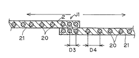
特に、上記問題はカーカスプライのジョイント部において発生しやすく、テキスタイルコードの場合、図9に示すようにトッピング反21の側端部を互いに重ね合わせて圧着し2〜5本のコード20が重なり合った、所謂オーバーラップジョイントJ1が行われ、ジョイント以外の部分に比べてジョイント部J1の周方向張力に対する剛性が大きくなるため、2次成形でのカーカスプライ2の拡張時に、図10に示すようにジョイント部J1は他の部分に比べて伸びにくくジョイント部J1でのコード20,20の間隔D3の変化が小さく、逆にジョイント隣接部に拡張応力が集中して伸びやすくなりコード間隔D4が大きくなり周方向でのエンド数分布の乱れを生じやすくしている。
In particular, the above problem is likely to occur at the joint portion of the carcass ply. In the case of a textile cord, as shown in FIG. 9, the side ends of the
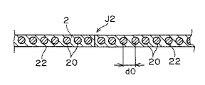
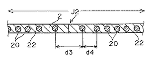
また、図11,12に示すように、トッピング反22の側端部同士を突き合わせてジョイントした、所謂バットジョイントJ2の場合も、拡張によりジョイント部にエンド数乱れd3,d4を生じる問題がある。
Also, as shown in FIGS. 11 and 12, the so-called butt joint J2 in which the side ends of the
このようなジョイント部でのエンド数分布乱れの問題を解決するものとして、カーカス材のジョイント部を予めカーカスコードと直交する方向に伸張処理すると共に、弾性回復後に互いにジョイントすることで、ジョイント部の引張り剛性を低下させた状態にして拡張しグリーンタイヤを形成する技術が開示されている(特許文献1)。 In order to solve such a problem of end number distribution disorder in the joint portion, the joint portion of the carcass material is previously stretched in a direction orthogonal to the carcass cord, and jointed together after the elastic recovery, the joint portion A technique for expanding and forming a green tire in a state where the tensile rigidity is lowered is disclosed (Patent Document 1).
また、カーカスコードからなる縦糸と有機繊維の横糸からなる簾織り物で、横糸の切断伸度を30%以下かつ破断強度を3〜7Nとし、横糸はカーカス層の形成工程前に切断され、3本以上のコードが上下に重ならずにジョイントされることが開示されている(特許文献2)。 The warp weave is composed of warp yarn made of carcass cord and weft yarn made of organic fiber. The weft yarn has an elongation at break of 30% or less and a breaking strength of 3 to 7 N. The weft yarn is cut before the formation of the carcass layer. It is disclosed that the above cords are jointed without overlapping vertically (Patent Document 2).
また、上記2次成形でのカーカスプライの拡張に伴い、タイヤ周方向のカーカスコードの実エンド数が減少し、カーカス剛性が低下することになる。トレッド部はスチールコードなどのベルト層を備えることでトレッド剛性が確保され、またサイドウォール部は拡張にようエンド数の減少が少なく、かつ硬質のビードフィラーゴムやビードフィラーに沿って外側に折り返したカーカスプライにより、或いはサイド補強層を設けることでサイド部剛性を確保することができるが、トレッド部に次いでエンド数減少の大きいショルダー部ではカーカス剛性が低下し操縦安定性が劣る原因になっている。
しかしながら、特許文献1のように、カーカス材のジョイント部のみをジョイント部の幅方向に均一に伸張処理することは難しく、特にタイヤ成形ドラム上における成形ジョイントではこのような伸張処理を行うことは困難である。
However, as in
また、特許文献2の技術では、特定の強伸度を有する横糸を簾織り物中で均一かつ細かく切断し、さらにジョイント部の重なりを2本以下に制限したものであってジョイント部の剛性差をある程度低減することはできるが、ジョイント隣接部でのコード間隔の乱れを解消するに到っていないのが実状である。
Further, in the technique of
特に、カーカスが1プライ構成のタイヤでは、上記ジョイント部での伸びの不均一性が顕著に現れやすく潜在的な解決課題であり、かつタイヤ軽量化に伴うトッピングゴムの薄肉化はこの伸びの不均一性を助長させるものとなり、また、サイドウォール部のゴム厚の薄肉化はジョイント部でのサイド部凹凸をタイヤ表面に表れやすくしている。 In particular, in a tire having a one-ply structure of carcass, the unevenness of elongation at the joint portion is likely to appear remarkably, and this is a potential problem to be solved. Uniformity is promoted, and the rubber thickness of the sidewall portion is reduced, so that the unevenness of the side portion at the joint portion easily appears on the tire surface.
また、ショルダーの剛性低下に対して、ショルダー部に新たに補強層を配設し剛性を向上することができるが、部材点数の増加やタイヤ成形工数増を伴ってタイヤのコストアップにつながり好ましくない。また、ベルトエッジ補強層をショルダー部に延長することが考えられるが、ベルトエッジ補強層は2次成形でタイヤに貼り付けることから、ベルトエッジからショルダー部の曲面上にかけて補強層を形成することは非常に困難なものとなり、成形機の改造や特殊な部材を必要としやはりコストアップを伴うものとなる。 In addition, it is possible to improve the rigidity by newly providing a reinforcing layer on the shoulder portion against the decrease in the rigidity of the shoulder, but this is not preferable because it leads to an increase in the cost of the tire with an increase in the number of members and the number of tire forming steps. . In addition, it is conceivable to extend the belt edge reinforcing layer to the shoulder portion, but since the belt edge reinforcing layer is affixed to the tire by secondary molding, it is not possible to form a reinforcing layer from the belt edge to the curved surface of the shoulder portion. It becomes very difficult and requires modification of the molding machine and special parts, which also increases costs.
本発明の目的は、上記問題に鑑みてなされたものであり、グリーンタイヤ成形時におけるカーカスプライ拡張に伴うカーカスコードのエンド数乱れを抑制するものであり、2次成形でのカーカスプライ拡張時の特定部分、特にジョイント部への拡張応力の集中を分散させてカーカスコードの乱れを低減しタイヤ全周でのエンド数分布の均一化を図ることで、ユニフォミティーを向上すると共にサイドウォール部の外観不良の低減を図る、と同時にタイヤ拡張に伴うエンド数減少によるショルダー部の剛性低下を補い操縦安定性の向上を図ることが1つの部材で実施することのできる空気入りラジアルタイヤを提供するものである。 The object of the present invention has been made in view of the above problems, and is intended to suppress the end number disturbance of the carcass cord accompanying the expansion of the carcass ply during green tire molding. Dispersing the concentration of expansion stress on specific parts, especially joints, reducing the disturbance of the carcass cord and making the end number distribution uniform throughout the entire tire, improving uniformity and the appearance of the sidewalls Provided is a pneumatic radial tire that can be implemented with a single member to reduce defects and simultaneously improve steering stability by compensating for a decrease in rigidity of the shoulder due to a decrease in the number of ends due to tire expansion. is there.
本発明の空気入りラジアルタイヤは、タイヤ赤道に対してほぼ直角にコード配列されたカーカスプライを左右一対のビード部のビードコアの周りで内側から外側に折り返し係止したカーカスと、前記カーカスの径方向外側のトレッド部に配設したベルトと、前記ビード部とトレッド部の間に一対のサイドウォール部とその上方にショルダー部を備え、タイヤ赤道を中心にしてトレッド部幅方向で分割されたカーカス補強層を前記カーカスとベルトとの間に有する空気入りラジアルタイヤにおいて、前記カーカス補強層は、前記トレッド部の両側部域からショルダー部に延びてタイヤ周方向の全周にわたり配設され、前記カーカス補強層が、有機繊維をタイヤ径方向に対して傾斜し配列させたゴム被覆層からなり、グリーンタイヤの1次成形において前記カーカスプライの円筒状成形体のトレッド部外周に貼り付けられた後、2次成形において前記カーカスプライと共に所定の外径に拡張されてなることを特徴とする。 A pneumatic radial tire according to the present invention includes a carcass in which a carcass ply arranged in a cord substantially at right angles to the tire equator is folded back from the inside to the outside around a bead core of a pair of left and right bead portions, and the radial direction of the carcass Carcass reinforcement with a belt arranged on the outer tread part, a pair of sidewall parts between the bead part and the tread part and a shoulder part above the bead part and divided in the tread part width direction around the tire equator In the pneumatic radial tire having a layer between the carcass and the belt, the carcass reinforcing layer extends from both side regions of the tread portion to a shoulder portion and is disposed over the entire circumference in the tire circumferential direction. The layer consists of a rubber coating layer in which organic fibers are inclined and arranged with respect to the tire radial direction. After adhered to the tread portion the outer periphery of the cylindrical molded body of the carcass ply have, and characterized by being extended to a predetermined outer diameter with said carcass ply in the secondary molding.
本発明の空気入りラジアルタイヤは、前記カーカス補強層が、平織物からなり、該平織物の経糸と緯糸とをタイヤ径方向に対してほぼ等しい角度で配設することができる。 In the pneumatic radial tire of the present invention, the carcass reinforcing layer is made of a plain woven fabric, and warps and wefts of the plain woven fabric can be disposed at substantially equal angles with respect to the tire radial direction.
また、本発明の空気入りラジアルタイヤにおいては、前記カーカス補強層が、有機繊維コードを平行に引き揃えて配列した簾織物からなるものでもよい。 In the pneumatic radial tire of the present invention, the carcass reinforcing layer may be made of a knit fabric in which organic fiber cords are arranged in parallel.
本発明の空気入りラジアルタイヤによれば、1次成形においてカーカスプライの円筒状成形体のトレッド両側部域からショルダー部にかけて周方向外周に貼り付けられたカーカス補強層が、2次成形での拡張時にカーカス補強層に含まれる有機繊維からなる平織物の経糸及び緯糸、或いは簾織物の有機繊維コードがその配列角度を変化させながら成形体周上で周方向に均等に滑るように伸張しながら拡張されるようになり、その拡張動作が内側のカーカスプライに作用しカーカスプライの拡張を周上で均等なものとしてカーカスコードのエンド数乱れを防ぐものとなる。 According to the pneumatic radial tire of the present invention, in the primary molding, the carcass reinforcing layer attached to the outer periphery in the circumferential direction from the tread both side regions to the shoulder portion of the cylindrical molded body of the carcass ply is expanded in the secondary molding. Sometimes the warp and weft of plain woven fabric made of organic fibers contained in the carcass reinforcing layer, or the organic fiber cord of cocoon woven fabric stretches to stretch evenly on the circumference of the molded product while changing its arrangement angle Thus, the expansion operation acts on the inner carcass ply, and the expansion of the carcass ply is made uniform on the circumference, thereby preventing the end number of the carcass cord from being disturbed.
すなわち、被覆ゴムによりカーカスプライと粘着状態にあるカーカス補強層側に拡張応力がかかることで、カーカスプライのジョイント部の剛性差に勝る拡張応力でカーカス補強層が拡張され、トレッド両側部域からショルダー部にかけて設けた補強層がトレッド部中央域からサイドウォール部に影響し、補強層の伸張動作に追従しカーカスプライが拡張されるようになる。その結果、ジョイント隣接部或いはタイヤ周上の特定箇所への部分的な応力集中を抑制し、カーカスコードを成形体周上で均等な間隔に拡張しエンド数分布の乱れを抑えるものとなり、トレッド部からサイドウォール部までのカーカスプライのエンド数分布を均等に保つようになる。 That is, by applying an expansion stress to the carcass ply layer side that is in an adhesive state with the carcass ply by the covering rubber, the carcass reinforcement layer is expanded with an expansion stress that exceeds the rigidity difference of the joint portion of the carcass ply, and the shoulder from both sides of the tread The reinforcing layer provided over the portion affects the sidewall portion from the central region of the tread portion, and the carcass ply is expanded following the extension operation of the reinforcing layer. As a result, partial stress concentration at the joint adjacent part or at a specific location on the tire circumference is suppressed, and the carcass cord is expanded to a uniform interval on the circumference of the molded body, thereby suppressing the disturbance of the end number distribution. The end number distribution of the carcass ply from the wall portion to the sidewall portion is kept uniform.
さらに、カーカス補強層がショルダー部を被って配されるので、拡張に伴うショルダー部のエンド数減少によるショルダー部の剛性低下を補強し、ショルダー部の剛性を高めて操縦安定性を向上させることができる。 In addition, since the carcass reinforcement layer is placed over the shoulder, it is possible to reinforce the reduction in the rigidity of the shoulder due to the decrease in the number of ends of the shoulder due to expansion, and to improve the steering stability by increasing the rigidity of the shoulder. it can.
このカーカス補強層としては、トレッド両側部域からショルダー部にかける拡張率の変化に追従しショルダー部の曲面を形成しやすい点で平織物が好適であり、経糸と緯糸とが交差角度を変化させながら伸張されるのでタイヤ周方向の拡張をより均一なものとし、さらにタイヤ径方向に対して45°のバイアスに配することで、略扇形状にタイヤ径方向に左右対称に変形し、トレッド部からサイドウォール部に至るジョイント部分での応力集中を効果的に抑えることができる。 As the carcass reinforcing layer, a plain woven fabric is suitable in that it easily follows the change in the expansion rate from the tread side areas to the shoulder part and easily forms a curved surface of the shoulder part. The warp and weft yarns change the crossing angle. Since the tire is stretched while being expanded, the tire circumferential direction is made more uniform, and further, by arranging it at a bias of 45 ° with respect to the tire radial direction, it is deformed symmetrically in the tire radial direction into a substantially fan shape, and the tread portion It is possible to effectively suppress the stress concentration at the joint part extending from the side wall part to the side wall part.
カーカス補強層に簾織物を用いると、補強層の伸張性や補強性の設計が容易となり、小型から大型までの各サイズタイヤのエンド数乱れに対応することができる。また補強層の厚みを薄肉に保ち軽量化を維持して走行中の発熱を抑え耐久性を維持するものとなる。この簾織物はタイヤ周方向の伸張性をタイヤ赤道の左右で均等に確保することから、経糸のみからなる簾織物或いは緯糸に高伸度糸を用いた簾織物であることが好ましい。 When a knit fabric is used for the carcass reinforcing layer, it is easy to design the reinforcing layer in terms of stretchability and reinforcing properties, and it is possible to cope with the irregular number of ends of each size tire from small to large. In addition, the thickness of the reinforcing layer is kept thin, the weight is kept low, heat generation during running is suppressed, and durability is maintained. In order to ensure uniform stretchability in the tire circumferential direction on the left and right sides of the tire equator, the kite fabric is preferably a kite fabric consisting of warp yarns or a kite fabric using high elongation yarns as weft yarns.
本発明の空気入りラジアルタイヤは、前記カーカス補強層が、トレッド両端部からトレッド総幅の10%〜30%幅でそれぞれトレッド部内方に入る位置を起点としてショルダー部に延びて配設される。 In the pneumatic radial tire of the present invention, the carcass reinforcing layer is disposed extending from the both ends of the tread to the shoulder portion starting from a position where the carcass reinforcing layer enters the tread portion inward at a width of 10% to 30% of the total tread width.
これによりカーカス補強層の拡張動作がトレッド部中央域まで作用し、トレッド部中央域にカーカス補強層が存在せずともエンド数分布の乱れをタイヤ径方向全体に抑制することができる。トレッド総幅の10%未満の位置からではトレッド中央域のエンド数乱れ防止の効果が十分でなく、30%を越えてトレッド部中央域近傍から幅広のカーカス補強層を設けてもエンド数乱れ防止の効果は向上せず、タイヤ重量の増加や部材の取り扱い性を低下させ、また、トレッド部の厚みが増して軽量化に反し、走行時発熱を大きくし耐久性低下の原因となる。 As a result, the expansion operation of the carcass reinforcing layer acts up to the central region of the tread portion, and even if the carcass reinforcing layer does not exist in the central region of the tread portion, disturbance of the end number distribution can be suppressed in the entire tire radial direction. From the position of less than 10% of the total width of the tread, the effect of preventing the disturbance of the number of ends in the center area of the tread is not sufficient, and even if a wide carcass reinforcing layer is provided from the vicinity of the center area of the tread exceeding 30% This does not improve the effect of the tire, reduces the weight of the tire and reduces the handleability of the member, and increases the thickness of the tread portion against the weight reduction.
特に、本発明は前記カーカスが1プライで構成される空気入りラジアルタイヤにおいて、拡張時にカーカスプライのコード間隔の乱れを抑える効果が大きく発揮され、タイヤユニフォミティーを改善し、サイドウォール部の凹凸の外観不良を低減するとともに操縦安定性を向上するものとなる。 Particularly, in the pneumatic radial tire in which the carcass is composed of one ply according to the present invention, the effect of suppressing the disturbance of the cord spacing of the carcass ply during expansion is greatly exerted, the tire uniformity is improved, and the unevenness of the sidewall portion is improved. The appearance defect is reduced and the steering stability is improved.
本発明の空気入りラジアルタイヤでは、2次成形での拡張時のカーカスプライへの部分的な応力集中を抑制し、カーカスコードを均等な間隔に拡張しエンド数乱れの発生を抑えユニフォミティーやサイドウォール部の凹凸発生を改善し、さらに操縦安定性を向上するものとなり、特に1プライ構成のラジアルタイヤのユニフォミティー不良や外観不良による製品不良を大幅に低減する効果が得られる。 In the pneumatic radial tire of the present invention, partial stress concentration on the carcass ply at the time of expansion in secondary molding is suppressed, and the carcass cords are expanded at equal intervals to suppress the occurrence of end number disturbances and uniformity and side As a result, the unevenness of the wall portion is improved, and the steering stability is further improved. In particular, the effect of greatly reducing product defects due to uniformity and appearance defects of a radial tire having a one-ply configuration can be obtained.
以下に、本発明の実施の形態を説明する。 Hereinafter, embodiments of the present invention will be described.
[第1の実施形態]
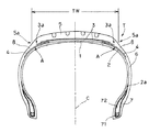
図1は本発明の第1の実施形態に係る乗用車用の空気入りラジアルタイヤ(以下、ラジアルタイヤという)Tを示すタイヤ断面図、図2はグリーンタイヤ9の拡張工程におけるカーカス補強層4を示すもので、(a)は拡張前のトレッド部展開平面図、(b)は拡張後のグリーンタイヤ9’の斜視図である。
[First Embodiment]
FIG. 1 is a tire cross-sectional view showing a pneumatic radial tire for passenger cars (hereinafter referred to as a radial tire) T according to a first embodiment of the present invention, and FIG. 2 shows a
本発明のラジアルタイヤTは、トレッド部5、サイドウォール部6とビード部7とから構成され、タイヤ赤道Cに対してほぼ90°の角度でコード配列されたカーカスプライ2を左右一対のビード部7のビードコア71の周りで内側から外側に折り返し係止したカーカス1と、カーカス1の径方向外側のトレッド部5に配設したベルト3と、ビード部7とトレッド部5の間に一対のサイドウォール部6とその上方にショルダー部8を備えている。
A radial tire T according to the present invention includes a
本発明のラジアルタイヤTにおいては、トレッド赤道Cを中心にしてトレッド部5の幅方向で左右に2分割されたカーカス補強層4,4が、カーカス1のタイヤ径方向の外側でベルト3との間に配され、前記カーカス補強層4はトレッド部5の両側部域からショルダー部8に延びてタイヤ周方向の全周にわたり連続してバンド状に配設されている。
In the radial tire T of the present invention, the
カーカス1は、1層のカーカスプライ2がタイヤ内側に配設され、ビードコア71の外周に配置されたビードフィラー72を包み込むようにタイヤ径方向外側に折り返し係止部2aを形成し固定されている。カーカスプライ2は、ポリエステル、ナイロン、レーヨン、アラミドなどの有機繊維コード、或いはスチールコードから構成され、有機繊維コードの場合は2プライ以上のプライ構成によるタイヤにも適用される。
The
ベルト層3は、タイヤ赤道Cに対して小角度(例えば、15〜35°)で交差するように積層した2枚のスチールコードなど剛直コードでなるベルトプライからなり、前記カーカス1を締め付けトレッド部5の剛性を高め、操縦安定性や低転がり抵抗性を確保している。
The
上記カーカス補強層4は、有機繊維がタイヤ径方向に対して傾斜し配列された伸張可能なゴム被覆層からなるシートにより構成され、2次成形における拡張時にカーカスプライ2の円筒状成形体の周方向に均一に伸張し、かつカーカスプライ2と共に拡張するものである。
The
上記カーカス補強層4,4は、図2(a)に示すように、グリーンタイヤの1次成形において形成されたカーカスプライ2の円筒状成形体9上に所定角度、所定幅で裁断されたカーカス補強層部材4,4が供給され、成形体9のトレッド部5の両側部域のトレッド赤道C側の内側に入ったベルト3下に当たる位置を起点にして左右対称にショルダー部8,8に延在し、円筒状成形体9の周方向全周にわたり連続してバンド状に貼り付けられる。
As shown in FIG. 2A, the
カーカス補強層4は、図2(b)に示すように、2次成形においてカーカスプライ2と共に所定の外径、例えば120〜180%伸張されながら拡張されタイヤ状の成形体9’に形成される。その後、トレッド部5及びショルダー部8のカーカス補強層4の外周部にベルト層3とトレッドゴムやサイドウォールゴムが積層されてグリーンタイヤが成形され、これを加硫成形してラジアルタイヤTが得られる。
As shown in FIG. 2 (b), the
カーカス補強層4としては、ナイロン、ポリエステルなどの有機繊維からなるマルチフィラメント糸又はモノフィラメント糸を経糸と緯糸として所定の密度で製織された平織物をゴム被覆し、例えば45°の所定角度、所定幅で裁断したゴム被覆平織物10が使用される。
As the
ゴム被覆平織物10は、2次成形におけるカーカスプライ2の円筒状成形体9の拡張時に、図に示すように、平織物10が拡張による変形応力を経緯糸が均等に受け、トレッド部5においてはその経糸及び緯糸の交差角度θをθ’に変化させながら周方向に均一に伸張しカーカスプライ2と共に拡張される。
As shown in the figure, the rubber-coated
このようにベルト部3からショルダー部8にかけて配されたカーカス補強層4では、拡張の際にベルト端部3aからショルダー部8にかけて拡張率が大きく変化する変曲部Aを有するため、この変曲部Aを越えるショルダー部8側では角度変化θ″が小さくなり、平織物10の経糸及び緯糸はベルト部端部3aからショルダー部8にかけて略扇形状の変形を示しながら周方向に均一に伸張しカーカスプライ2と共に拡張される。
Since the
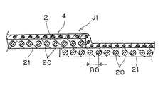
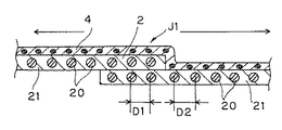
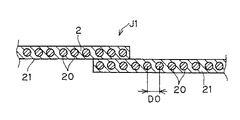
この拡張の際に、カーカスプライ2のジョイントがトッピング反21端部のオーバーラップジョイントJ1の場合は、図3,4に示すように、カーカス補強層4側の拡張動作が主導的なものとなることで、カーカスプライ2の拡張動作がカーカス補強層4の伸張動作に追従し拡張されるものとなり、ジョイント部J1での剛性差を解消してジョイント隣接部への部分的な応力集中を抑制する。
In this expansion, when the joint of the
これにより、コード20,20の間隔D0がジョイント部J1とその隣接部で伸張長さに大きな差を生じることなく拡張されるようになり、ジョイント部J1でのコード間隔D1とその隣接部でのコード間隔D2とがほぼ同一になるように拡張されエンド数乱れの発生を抑えるようになる。
As a result, the distance D0 between the
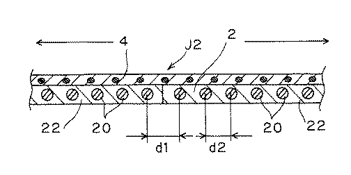
また、カーカスプライ2のジョイントがトッピング反22同士のバットジョイントJ2の場合は、図5,6に示すように、ジョイント部分J2でのジョイントによるゴム粘着力と隣接正常部でのトッピングゴムによる粘着力の差を打ち消し、ジョイント部J2への拡張応力の集中を抑制することができる。
Further, when the joint of the
これにより、ジョイント部J2両隣のコード20,20間の目開きを防ぐようになり、拡張前のコード間隔d0が、ジョイント部d1とその隣接部でのコード間隔d2で伸張長さに差を生じることなく拡張されるようになり、全周でほぼ均等なエンド数分布が得られる。
As a result, the opening between the
さらに、カーカス補強層4は、トレッド部5の両側部域からショルダー部8に延在し、ショルダー部8を被って配設されるので、拡張に伴うエンド数減少によるショルダー部8の剛性低下を補強し、ショルダー部8の剛性を高めて操縦安定性を向上させるものとなる。
Further, since the
従って、カーカス補強層4は、カーカスプライ2の拡張時にカーカスプライ2の拡張動作を抑えてカーカスプライ2の拡張動作に勝る補強効果とショルダー部8の補強効果を満たすものが必要となり、このためには、平織物10の経緯糸構成や打ち込み密度、配列角度等を調整することで得られる。
Therefore, the
また、カーカス補強層4は、カーカスプライ2の拡張時に成形体9の周方向に伸張されることで、成形体9幅方向には収縮されるようになるので、この点も考慮しカーカス補強層4の構成を設計する必要がある。
Further, since the
また、カーカス補強層4は、トレッド端部5aからトレッド総幅の10%〜30%の幅でトレッド部5の中央域に向かう内方に入る側部域にある位置を起点としてショルダー部8に延在し配されるのが好ましい。
Further, the
これによりカーカス補強層4の拡張動作が、トレッド部5中央域まで作用し、中央域のカーカスコードの動作に追従しサイドウォール部6に至るまでのエンド数分布の乱れを抑制することができる。カーカス補強層4がトレッド総幅の10%未満の位置を起点にする場合はトレッド中央域のエンド数乱れ防止の効果が十分でなくタイヤ径方向全体の乱れを生じるおそれがあり、30%を越えてトレッド部中央域近傍から幅広のカーカス補強層を設けてもエンド数乱れ防止の効果は向上せず、タイヤ重量の増加や部材の取り扱い性を低下させ、また、トレッド部の厚みが増して軽量化に反し、走行時発熱を大きくし耐久性低下の原因となる。
Thereby, the expansion operation of the
また、カーカス補強層4は、ショルダー部8を越えてサイドウォール部6に至るまで設けてサイド部剛性を向上することもできるが、タイヤ重量増や成形工数増、コスト等の上昇を伴うこともあり、本発明の目的を達成する範囲ではショルダー部8で終端すれば十分である。また、ビード部7までカーカス補強層4を延長するとサイド剛性が高くなすぎ屈曲耐久性や乗り心地を損ない好ましくない。
Further, the
本実施形態のように、前記カーカス補強層4が平織物10からなる場合は、その経糸と緯糸とがタイヤ径方向に対してほぼ45°の角度で用いられることが好ましく、これにより2次成形における拡張時に拡張応力を経緯糸が均等に受けてタイヤ周方向での伸張を均一にし、パンタグラフ変形によりカーカスプライのジョイント部J1,J2での剛性差の解消を効果的なものとすることができる。但し、平織物10の経緯糸が異なる構成や密度でなる場合はこの限りではない。
When the
上記経糸及び緯糸を構成する有機繊維としては、ナイロン6,66等のナイロン繊維、ポリエチレンテレフタレート等のポリエステル繊維、ビニロンなどの合成繊維が挙げられるが、中でもナイロン6、66が強度が高く、ゴムとの接着性に優れ、かつ低荷重域の伸びが比較的大きいことから、拡張時の伸張性に有利に働きカーカス補強層4のパンタグラフ変形を得やすくなることから好ましい。
Examples of the organic fibers constituting the warp and the weft include nylon fibers such as
前記平織物を構成する経糸と緯糸は、繊度200〜1100デシテックス(dtex)のマルチフィラメントからなることが好ましく、太さが1100dtexを越えると平織物10が厚くなりカーカス補強層4の厚みが増してゴムの使用量が増加しタイヤの軽量化や発熱により耐久性を低下させ、逆に細すぎると平織物10の伸張変形がカーカスプライの拡張動作に引きずられてしまいカーカスコードの乱れを抑えられなくなり、200dtex未満の細いコードを高密度で製織したものは上記パンタグラフ変形が制限され経緯糸の角度変化がスムーズでなくなり、さらに平織物を挟むゴムのブリッジが不足し接着性の低下を招くことにもなる。
The warp and weft constituting the plain woven fabric are preferably made of multifilaments having a fineness of 200 to 1100 dtex (dtex). When the thickness exceeds 1100 dtex, the plain woven
ここで、平織物10の経緯糸の打ち込み密度は、拡張時に交差角度をスムーズに変化させ、かつカーカスプライ2とベルト層3との接着性を良好に維持する観点から30〜50本/50mm程度、より好ましくは35〜50本/50mm程度が望ましい範囲であり、コードの太さとの関係を考慮し設計する必要がある。なお、経緯糸の太さ、打ち込み密度は、拡張時のパンタグラフ変形をスムーズにするため、同じ太さ、密度とすることが好ましい。
Here, the weft density of the warp yarn of the plain woven
[第2の実施形態]
第2の実施形態では、カーカス補強層4として、ナイロン、ポリエステル、ビニロンなどの有機繊維からなるマルチフィラメントコード又はモノフィラメントコードを所定密度で平行に引き揃えたコード配列体、すなわち緯糸無しの簾織物11にゴム被覆したものを所定の角度(30〜60°程度)、所定幅で裁断したものが用いられる。
[Second Embodiment]
In the second embodiment, the
図7に示すように、ゴム被覆簾織物11では、2次成形におけるカーカスプライ2の円筒状成形体9の拡張時に、簾織物11が拡張による変形応力を受けコードの配列角度θ1(タイヤ径方向との角度)をトレッド部5ではθ1’に、変曲部Aを越えるショルダー部8側では角度変化θ″を小さく変化させながら周方向に均一に伸張しカーカスプライ2と共に拡張されようになり、周方向でのエンド数の乱れを防ぐことができる。
As shown in FIG. 7, in the rubber-coated woven
また、この簾織物11では補強層コード太さや打ち込み密度の選択が比較的容易であるので、カーカス補強層4の補強効果を調整することも容易に可能となる。
In addition, since the selection of the reinforcing layer cord thickness and the driving density is relatively easy in the woven
上記簾織物11をカーカス補強層4として用いる場合は、補強層内の配列コードを経糸として緯糸により簾織物に製織したものが簾織物の製造上容易であるが、伸びの小さい綿糸等を緯糸に用いると拡張時に補強コードと緯糸とにかかる応力が不均等になって簾織物11の周方向への伸張変形が不均一となり逆にジョイント部以外においてもカーカスコードの乱れを生じやすくする。
In the case of using the cocoon woven
従って、緯糸を用いる場合は、切断伸びが50%以上、好ましくは100%以上の高伸度糸を用いることで、拡張時に補強コードにのみ応力がかかるようになり、タイヤ周上でより均等な伸張変形が得られるようになる。さらには、緯糸無しの簾織物を用いることが最も好ましい形態である。 Therefore, when wefts are used, by using high elongation yarns having a cut elongation of 50% or more, preferably 100% or more, stress is applied only to the reinforcing cords during expansion, and the tire circumference is more even on the tire circumference. An extensional deformation can be obtained. Furthermore, it is the most preferable form to use a woven fabric without weft.
補強コードのタイヤ径方向に対する配列角度θ1は、30〜60°程度、好ましくは40〜50°であり、θ1が小さすぎると補強層が伸張しやすくなりカーカスプライのエンド数分布の乱れを防ぐことができず、カーカスコードとの交差角度が小さくなりショルダーぶの補強効果が低下する。θ1が大きすぎると十分な伸張変形が得られず、逆にエンド数乱れを生じやすくする。 The arrangement angle θ1 of the reinforcing cord with respect to the tire radial direction is about 30 to 60 °, preferably 40 to 50 °. If θ1 is too small, the reinforcing layer is easily stretched to prevent the end number distribution of the carcass ply from being disturbed. The crossing angle with the carcass cord becomes small and the effect of reinforcing the shoulder strap is reduced. If θ1 is too large, sufficient extensional deformation cannot be obtained, and conversely, end number disturbance is likely to occur.
また、カーカス補強層4としては、上記平織物や簾織物の他に、ナイロン、ポリエステル、ビニロンなどの有機繊維からなる短繊維を配合したゴム組成物からなる短繊維入りゴムシートを所定の角度、所定幅で裁断したものも使用することができる。
Further, as the
以下、実施例に基づいて本発明をさらに詳しく説明する。 Hereinafter, the present invention will be described in more detail based on examples.
表1に示す仕様に従い、ナイロン66(Ny66)のフィラメント数14本、470dtexのマルチフィラメント糸(比較例4はフィラメント数28本、940dtexを使用)を経糸及び緯糸として製織した平織物、およびナイロン66(Ny66)、940dtex/2のコードを簾織に製織したものをカーカス補強層に適用し(実施例3は切断伸びが100%のポリエステル高伸度糸、比較例5は切断伸びが10%の綿糸を緯糸に使用)、図1に示すタイヤ構造を有する各実施例、比較例の空気入りラジアルタイヤを試作し、エンド数分布、ユニフォミティー、サイド部凹凸発生、操縦安定性(乗り心地を含む)、耐久性について下記の試験方法に従い評価を行い、その結果を表1に示す。 In accordance with the specifications shown in Table 1, nylon 66 (Ny66) 14 filaments, 470 dtex multifilament yarn (Comparative Example 4 uses 28 filaments, 940 dtex is used), a plain fabric woven as warp and weft, and nylon 66 (Ny66), a 940 dtex / 2 cord woven into a knot weave was applied to the carcass reinforcing layer (Example 3 is a polyester high elongation yarn having a cut elongation of 100%, Comparative Example 5 has a cut elongation of 10%. 1), tires shown in FIG. 1 having the tire structure shown in FIG. 1, and comparative examples of pneumatic radial tires were manufactured as prototypes. End number distribution, uniformity, side unevenness, steering stability (including ride comfort) ), Durability was evaluated according to the following test method, and the results are shown in Table 1.
試作タイヤは、サイズ175/70R13 82S、カーカスプライはポリエステル1670dtex/2(エンド数23本/25mm)の1プライ、ベルト層はスチールコード2+2×0.25(エンド数19本/25mm)の交差角度23度の2層構造として各タイヤに共通である。
The prototype tire is size 175 / 70R13 82S, the carcass ply is 1 ply polyester 1670 dtex / 2 (23 ends / 25 mm), and the belt layer is
各カーカス補強層は、ゴム被覆後の平織物及び簾織物の経糸に対して45度(60度)の角度で所定幅に裁断したカーカス補強層を、1次成形で形成された円筒状成形体のトレッド両側部のトレッド総幅の20%幅でそれぞれトレッド部の内方に入る位置を起点(各実施例、比較例に共通)としてショルダー部にわたりカーカス周上に貼り付け、2次成形でカーカスプライと共に所定外径に(135%)拡張した後、ベルト層及びトレッドゴムを積層しグリーンタイヤを成形し、常法による加硫工程を経てタイヤを製造した(図8のタイヤ断面図参照)。
Each carcass reinforcing layer is a cylindrical molded body formed by primary molding of a carcass reinforcing layer cut to a predetermined width at an angle of 45 degrees (60 degrees) with respect to warp yarns of a plain woven fabric and a warp woven fabric coated with rubber. Affixed on the circumference of the carcass over the shoulder as a starting point (common to each example and comparative example) at a
[試験方法]
エンド数分布:タイヤバットレス部の周方向でエンド数分布の最も乱れの大きい部分120cmを測定試料とし、これをさらに6等分して各部分の最大コード間隔と最小コード間隔を測定し、測定数12の標準偏差を求め、比較例1を100とする指数で示した。数値が小さいほど良い。
[Test method]
End number distribution: The portion with the largest disturbance of the end number distribution 120cm in the circumferential direction of the tire buttress part is used as a measurement sample, and this is further divided into six parts to measure the maximum cord interval and the minimum cord interval of each part. The standard deviation of 12 was calculated | required and it showed by the index | exponent which makes the comparative example 1 100. Smaller numbers are better.
ユニフォミティー:JASO C607の自動車用タイヤのユニフォミティー試験方法に準拠してラジアルフォースバリエーション(RFV)を測定し、比較例1を100とする指数で示した。数値が小さいほど良い。 Uniformity: Radial force variation (RFV) was measured according to JASO C607 automotive tire uniformity test method, and Comparative Example 1 was shown as an index of 100. Smaller numbers are better.
サイド部凹凸:JATMAに規定の標準リムに空気圧300kPaでリム組みし、サイドウォール部における凹凸発生度合を目視によって観察し評価した。 Side unevenness: A rim was assembled on a standard rim prescribed by JATMA at an air pressure of 300 kPa, and the degree of unevenness in the side wall was visually observed and evaluated.
操縦安定性:排気量1600CCの前輪駆動式乗用車に同種のタイヤ4本を装着し、アスファルト舗装の周回路テストコースを3名のテストドライバーによって実車走行を行い、ハンドル応答性、剛性感、グリップ感、及び乗り心地を官能評価により実施した。比較例1をコントロールとして、優れるものを「○」、同等のものを「△」、劣るものを「×」と評価し示した。 Steering stability: A front-wheel-drive passenger car with a displacement of 1600 CC is fitted with four tires of the same type, and the asphalt pavement circuit test course is run by three test drivers. , And riding comfort were performed by sensory evaluation. Using Comparative Example 1 as a control, an excellent one was evaluated as “◯”, an equivalent one as “Δ”, and an inferior one as “X”.
耐久性:FMVSS109(米国自動車安全基準)に準拠し耐久試験を行い、規定合格時間走行しタイヤ外観に異常が認められたものを「×」とし、異常がなかったものはさらに最大荷重の120%を負荷して合計の走行距離が8,000Kmまで走行試験を実施した後、タイヤ外観に異常発生が認められなかったものを「○」、タイヤ外観に亀裂等の異常の発生が認められたものを「△」と評価した。 Durability: An endurance test was conducted in accordance with FMVSS109 (American Automobile Safety Standards), and the tires that passed the specified passing time and had an abnormality in the appearance of the tire were marked “x”, and those without an abnormality were 120% of the maximum load. After carrying out a running test up to a total mileage of 8,000km with a load applied, “○” indicates that no abnormality was observed on the tire appearance, and abnormality such as cracks was observed on the tire appearance. Was evaluated as “Δ”.
表1に示す結果から明らかなように、Ny66のマルチフィラメント糸を経緯糸とする平織物をカーカス補強層に用いた実施例1,2、高伸度糸を緯糸に用いたNy66コードの簾織物を用いた実施例3は、従来のカーカス補強層の無い比較例1に比べグリーンタイヤの2次成形でのカーカスプライの拡張が全周で均一なものとなりエンド数分布の乱れが小さく、ユニフォミティーが良好で、サイド部凹凸発生がなく外観不良を低減するものとなり、かつ操縦安定性を向上して、耐久性にも優れている。 As is apparent from the results shown in Table 1, Examples 1 and 2 using a plain weave made of Ny66 multifilament yarn as a warp weft for the carcass reinforcing layer, Ny66 cord raft using a high elongation yarn as the weft In Example 3, which uses, the expansion of the carcass ply in the secondary molding of the green tire is uniform over the entire circumference compared to Comparative Example 1 without the conventional carcass reinforcing layer, and the disturbance in the end number distribution is small. Is good, and there is no unevenness on the side part, and the appearance defect is reduced, and the steering stability is improved and the durability is excellent.
これに対して、カーカス補強層の幅が狭い比較例2ではカーカス補強層によるカーカスプライの抑制効果が小さく若干のエンド数乱れを生じ、補強層のショルダー部に占める割合が小さいためショルダー部の補強効果に乏しく操縦安定性が改善されない。また、カーカス補強層の幅が広い比較例3ではエンド数乱れを防止することはできるが、カーカス補強層がビード部まで被うため、操縦安定性は良好であるがゴツゴツ感が大で乗り心地が悪化する。平織物の経緯糸に太い糸を用いた比較例4では、トレッド部の厚み、重量が増加し発熱による接着破壊から亀裂が発生した。また、緯糸に伸びの小さい綿糸を用いた比較例5は、補強層の伸張が均一にならずエンド数分布が悪化し、ユニフォミティー、サイド外観が悪化し、ハンドルのふらつきによる操縦安定性の低下、エンド数乱れによるカーカスコードの部分的な偏りよる耐久性の低下を招く結果となった。 On the other hand, in Comparative Example 2 in which the width of the carcass reinforcing layer is narrow, the effect of suppressing the carcass ply by the carcass reinforcing layer is small, causing a slight end number disorder, and the proportion of the reinforcing layer in the shoulder portion is small. It is not effective and steering stability is not improved. Further, in Comparative Example 3 in which the width of the carcass reinforcing layer is wide, it is possible to prevent the end number from being disturbed, but since the carcass reinforcing layer covers the bead portion, the driving stability is good, but the rugged feeling is great and the ride comfort Gets worse. In Comparative Example 4 in which a thick yarn was used for the warp and weft of the plain woven fabric, the thickness and weight of the tread portion increased, and cracks occurred due to adhesion failure due to heat generation. Further, in Comparative Example 5 using cotton yarn having a small elongation for the weft, the extension of the reinforcing layer is not uniform, the end number distribution is deteriorated, the uniformity and the side appearance are deteriorated, and the steering stability is lowered due to the wobbling of the steering wheel. As a result, the durability was lowered due to the partial deviation of the carcass cord due to the disturbance of the number of ends.
以上説明したように、本発明の空気入りラジアルタイヤは、乗用車用からトラック・バス用などの各種サイズのテキスタイルカーカスおよびスチールカーカスを備える空気入りラジアルタイヤに適用することができ、特にカーカスが1プライ構成の乗用車用ラジアルタイヤのユニフォミティーと操縦安定性の向上に有用である。 As described above, the pneumatic radial tire of the present invention can be applied to pneumatic radial tires including textile carcasses of various sizes for passenger cars, trucks and buses, and steel carcass. This is useful for improving the uniformity and handling stability of the radial tires for passenger cars with the construction.
1……カーカス
2……カーカスプライ
3……ベルト
4……カーカス補強層
5……トレッド部
6……サイドウォール部
7……ビード部
8……ショルダー部
9……カーカスプライの円筒状成形体
10……ゴム被覆平織物
11……ゴム被覆簾織物
20……カーカスコード
21,22……トッピング反
C……タイヤ赤道
D、d……コード間隔
J……ジョイント
T……空気入りラジアルタイヤ
θ……有機繊維の交差角度、又はタイヤ径方向に対する傾斜角度
DESCRIPTION OF
Claims (4)
前記カーカス補強層は、前記トレッド部の両側部域からショルダー部に延びてタイヤ周方向の全周にわたり配設され、
前記カーカス補強層が、有機繊維をタイヤ径方向に対して傾斜し配列させたゴム被覆層からなり、グリーンタイヤの1次成形において前記カーカスプライの円筒状成形体のトレッド部外周に貼り付けられた後、2次成形において前記カーカスプライと共に所定の外径に拡張されてなる
ことを特徴とする空気入りラジアルタイヤ。 A carcass in which a carcass ply that is arranged in a cord substantially at right angles to the tire equator is folded back from the inside to the outside around a bead core of a pair of left and right bead portions, and a belt disposed on a tread portion on the radially outer side of the carcass A carcass reinforcing layer provided between the bead portion and the tread portion and having a pair of sidewall portions and a shoulder portion above the sidewall portion and divided in the tread width direction about the tire equator. In the pneumatic radial tire that has
The carcass reinforcing layer extends from both side regions of the tread portion to a shoulder portion and is disposed over the entire circumference in the tire circumferential direction.
The carcass reinforcing layer is composed of a rubber coating layer in which organic fibers are inclined and arranged with respect to the tire radial direction, and is attached to the outer periphery of the tread portion of the cylindrical molded body of the carcass ply in the primary molding of the green tire. Thereafter, a pneumatic radial tire characterized by being expanded to a predetermined outer diameter together with the carcass ply in secondary molding.
ことを特徴とする請求項1〜3のいずれかに記載の空気入りラジアルタイヤ。
The carcass reinforcing layer is disposed to extend from the both ends of the tread to the shoulder portion starting from a position where the width of the tread portion is inwardly 10% to 30% of the total width of the tread. The pneumatic radial tire according to any one of the above.
Priority Applications (1)
| Application Number | Priority Date | Filing Date | Title |
|---|---|---|---|
| JP2004119570A JP2005297871A (en) | 2004-04-14 | 2004-04-14 | Pneumatic radial tire |
Applications Claiming Priority (1)
| Application Number | Priority Date | Filing Date | Title |
|---|---|---|---|
| JP2004119570A JP2005297871A (en) | 2004-04-14 | 2004-04-14 | Pneumatic radial tire |
Publications (1)
| Publication Number | Publication Date |
|---|---|
| JP2005297871A true JP2005297871A (en) | 2005-10-27 |
Family
ID=35329928
Family Applications (1)
| Application Number | Title | Priority Date | Filing Date |
|---|---|---|---|
| JP2004119570A Pending JP2005297871A (en) | 2004-04-14 | 2004-04-14 | Pneumatic radial tire |
Country Status (1)
| Country | Link |
|---|---|
| JP (1) | JP2005297871A (en) |
Cited By (5)
| Publication number | Priority date | Publication date | Assignee | Title |
|---|---|---|---|---|
| JP2012111266A (en) * | 2010-11-19 | 2012-06-14 | Yokohama Rubber Co Ltd:The | Pneumatic tire for racing cart |
| CN112976942A (en) * | 2019-12-13 | 2021-06-18 | 通伊欧轮胎株式会社 | Pneumatic tire and method for manufacturing same |
| EP3922485A1 (en) * | 2020-06-12 | 2021-12-15 | Sumitomo Rubber Industries, Ltd. | Tire for kart |
| CN114555347A (en) * | 2019-10-16 | 2022-05-27 | 米其林集团总公司 | Tire having improved uniformity and method of making same |
| US12350982B2 (en) | 2019-10-16 | 2025-07-08 | Compagnie Generale Des Etablissements Michelin | Low-noise tire and method for manufacturing same |
Citations (1)
| Publication number | Priority date | Publication date | Assignee | Title |
|---|---|---|---|---|
| JP2003191720A (en) * | 2001-12-27 | 2003-07-09 | Sumitomo Rubber Ind Ltd | Pneumatic radial tire |
-
2004
- 2004-04-14 JP JP2004119570A patent/JP2005297871A/en active Pending
Patent Citations (1)
| Publication number | Priority date | Publication date | Assignee | Title |
|---|---|---|---|---|
| JP2003191720A (en) * | 2001-12-27 | 2003-07-09 | Sumitomo Rubber Ind Ltd | Pneumatic radial tire |
Cited By (5)
| Publication number | Priority date | Publication date | Assignee | Title |
|---|---|---|---|---|
| JP2012111266A (en) * | 2010-11-19 | 2012-06-14 | Yokohama Rubber Co Ltd:The | Pneumatic tire for racing cart |
| CN114555347A (en) * | 2019-10-16 | 2022-05-27 | 米其林集团总公司 | Tire having improved uniformity and method of making same |
| US12350982B2 (en) | 2019-10-16 | 2025-07-08 | Compagnie Generale Des Etablissements Michelin | Low-noise tire and method for manufacturing same |
| CN112976942A (en) * | 2019-12-13 | 2021-06-18 | 通伊欧轮胎株式会社 | Pneumatic tire and method for manufacturing same |
| EP3922485A1 (en) * | 2020-06-12 | 2021-12-15 | Sumitomo Rubber Industries, Ltd. | Tire for kart |
Similar Documents
| Publication | Publication Date | Title |
|---|---|---|
| US2895525A (en) | Pneumatic tire | |
| US20130284337A1 (en) | Accordion spiral overlay for a pneumatic tire | |
| EP3296126B1 (en) | Pneumatic tire | |
| CN101031440B (en) | Pneumatic tire and its manufacturing method | |
| EP2463124A2 (en) | Pneumatic tire | |
| JP4547379B2 (en) | Pneumatic tire | |
| JP4034140B2 (en) | Radial tire | |
| JP2009001108A (en) | Pneumatic radial tire | |
| JP2005297871A (en) | Pneumatic radial tire | |
| JP2000071714A (en) | Pneumatic radial tire for motor vehicle | |
| JP3641203B2 (en) | Pneumatic tire and manufacturing method thereof | |
| US20160288574A1 (en) | Crown reinforcement for a pneumatic tire | |
| US20160288572A1 (en) | Bidirectional monobelt construction for a pneumatic tire | |
| US20160288573A1 (en) | Continuous crown reinforcement for a pneumatic tire | |
| JP2005219550A (en) | Pneumatic radial tire | |
| EP3795381B1 (en) | Pneumatic tyre | |
| JP3061353B2 (en) | Pneumatic tire | |
| JPH0137284B2 (en) | ||
| JP3559399B2 (en) | Radial tire | |
| JP2004136839A (en) | Pneumatic tire | |
| JP2001001724A (en) | Pneumatic radial tire | |
| JP2004351993A (en) | Pneumatic radial tire | |
| JPH09193610A (en) | Pneumatic radial tire | |
| JP2001171311A (en) | Pneumatic radial tire for passenger car | |
| US20170144485A1 (en) | Bidirectional monobelt construction for a pneumatic tire |
Legal Events
| Date | Code | Title | Description |
|---|---|---|---|
| A621 | Written request for application examination |
Free format text: JAPANESE INTERMEDIATE CODE: A621 Effective date: 20070131 |
|
| A977 | Report on retrieval |
Free format text: JAPANESE INTERMEDIATE CODE: A971007 Effective date: 20091224 |
|
| A131 | Notification of reasons for refusal |
Free format text: JAPANESE INTERMEDIATE CODE: A131 Effective date: 20100112 |
|
| A02 | Decision of refusal |
Free format text: JAPANESE INTERMEDIATE CODE: A02 Effective date: 20100713 |
