EP1604606A1 - Capsule type endoscope - Google Patents
Capsule type endoscope Download PDFInfo
- Publication number
- EP1604606A1 EP1604606A1 EP04721303A EP04721303A EP1604606A1 EP 1604606 A1 EP1604606 A1 EP 1604606A1 EP 04721303 A EP04721303 A EP 04721303A EP 04721303 A EP04721303 A EP 04721303A EP 1604606 A1 EP1604606 A1 EP 1604606A1
- Authority
- EP
- European Patent Office
- Prior art keywords
- capsule endoscope
- surface emission
- light source
- endoscope according
- emission light
- Prior art date
- Legal status (The legal status is an assumption and is not a legal conclusion. Google has not performed a legal analysis and makes no representation as to the accuracy of the status listed.)
- Withdrawn
Links
Images



Classifications
-
- A—HUMAN NECESSITIES
- A61—MEDICAL OR VETERINARY SCIENCE; HYGIENE
- A61B—DIAGNOSIS; SURGERY; IDENTIFICATION
- A61B1/00—Instruments for performing medical examinations of the interior of cavities or tubes of the body by visual or photographical inspection, e.g. endoscopes; Illuminating arrangements therefor
- A61B1/04—Instruments for performing medical examinations of the interior of cavities or tubes of the body by visual or photographical inspection, e.g. endoscopes; Illuminating arrangements therefor combined with photographic or television appliances
- A61B1/041—Capsule endoscopes for imaging
-
- A—HUMAN NECESSITIES
- A61—MEDICAL OR VETERINARY SCIENCE; HYGIENE
- A61B—DIAGNOSIS; SURGERY; IDENTIFICATION
- A61B1/00—Instruments for performing medical examinations of the interior of cavities or tubes of the body by visual or photographical inspection, e.g. endoscopes; Illuminating arrangements therefor
- A61B1/00064—Constructional details of the endoscope body
- A61B1/00071—Insertion part of the endoscope body
- A61B1/0008—Insertion part of the endoscope body characterised by distal tip features
- A61B1/00096—Optical elements
-
- A—HUMAN NECESSITIES
- A61—MEDICAL OR VETERINARY SCIENCE; HYGIENE
- A61B—DIAGNOSIS; SURGERY; IDENTIFICATION
- A61B1/00—Instruments for performing medical examinations of the interior of cavities or tubes of the body by visual or photographical inspection, e.g. endoscopes; Illuminating arrangements therefor
- A61B1/04—Instruments for performing medical examinations of the interior of cavities or tubes of the body by visual or photographical inspection, e.g. endoscopes; Illuminating arrangements therefor combined with photographic or television appliances
- A61B1/05—Instruments for performing medical examinations of the interior of cavities or tubes of the body by visual or photographical inspection, e.g. endoscopes; Illuminating arrangements therefor combined with photographic or television appliances characterised by the image sensor, e.g. camera, being in the distal end portion
- A61B1/051—Details of CCD assembly
-
- A—HUMAN NECESSITIES
- A61—MEDICAL OR VETERINARY SCIENCE; HYGIENE
- A61B—DIAGNOSIS; SURGERY; IDENTIFICATION
- A61B1/00—Instruments for performing medical examinations of the interior of cavities or tubes of the body by visual or photographical inspection, e.g. endoscopes; Illuminating arrangements therefor
- A61B1/06—Instruments for performing medical examinations of the interior of cavities or tubes of the body by visual or photographical inspection, e.g. endoscopes; Illuminating arrangements therefor with illuminating arrangements
- A61B1/0607—Instruments for performing medical examinations of the interior of cavities or tubes of the body by visual or photographical inspection, e.g. endoscopes; Illuminating arrangements therefor with illuminating arrangements for annular illumination
-
- A—HUMAN NECESSITIES
- A61—MEDICAL OR VETERINARY SCIENCE; HYGIENE
- A61B—DIAGNOSIS; SURGERY; IDENTIFICATION
- A61B1/00—Instruments for performing medical examinations of the interior of cavities or tubes of the body by visual or photographical inspection, e.g. endoscopes; Illuminating arrangements therefor
- A61B1/06—Instruments for performing medical examinations of the interior of cavities or tubes of the body by visual or photographical inspection, e.g. endoscopes; Illuminating arrangements therefor with illuminating arrangements
- A61B1/0661—Endoscope light sources
- A61B1/0684—Endoscope light sources using light emitting diodes [LED]
Definitions
- the present invention relates to a capsule endoscope which picks up an image of the body cavity by introducing, in the living body, a capsule portion incorporating an observation optical unit and an illumination unit.
- an endoscope apparatus has widely been used.
- an observation unit arranged to an edge portion of an elongated insertion portion of an endoscope is inserted to an observing region in the body cavity as a target.
- the observation unit faces the observing region as the target and thus an observed image of the observing region as the target is displayed on a screen of an observation device.
- the present invention is to provide a capsule endoscope reduced in size and highly functional, which is superior in luminance and in light distribution and may prevent any thermal load from being applied to an image pick-up element.
- a capsule endoscope includes a capsule portion.
- the capsule portion includes at least an observation optical unit having an optical lens and an image pick-up element that form an objective optical system, an illumination unit having an illumination substrate, a surface emission light source and a light-emitting control circuit, peripheral-circuit parts which form various circuits such as a signal processing circuit, a receiving/transmitting circuit and a control circuit, and a power source unit which supplies power to the observation optical unit, the illumination unit and the peripheral-circuit parts. Therefore, the luminance blur and the light-distribution blur of the illumination unit are solved. Further, the space of the capsule portion for providing the illumination unit in the longitudinal direction can be reduced. Thus, the capsule portion is reduced in size, and the space in the capsule portion can be effectively used.
- the surface emission light source in the capsule endoscope according to the present invention is an electroluminescence device. By this, consumption of power at the illumination unit is largely reduced.
- a capsule endoscope 1 comprises in a capsule portion 2: an observation optical unit; an illumination unit; peripheral-circuit parts; and a power source unit according to the first embodiment, which will be described later.
- the entire surface of the illumination substrate 21 may be divided into a plurality of surfaces with a predetermined area to form the EL device 22 and the desired surface of the EL device 22 may properly emit light.
- the brightness of illumination light can properly be changed in accordance with the observing position in the body cavity through which the capsule endoscope passes.
- the EL device 22a having the R, G, B matrixes is formed on the entire surface of the illumination substrate 21.
- a red EL device 22r, a green EL device 22g, and a blue EL device 22b are formed as three divided portions on the surface of the illumination substrate 21 and are colored to white by complementary colors. Then, white light-emission is efficiently possible. Thus, a preferable observed image is obtained.
- the signal processing circuit performs processing for converting an optical image formed on the image pick-up surface of the image pick-up element 13 into an image signal and generates a driving signal for driving the image pick-up element 13.
- the receiving and transmitting circuit performs predetermined processing of the image signal generated by the signal processing circuit, transmits the image signal to the observation device as the external device (not shown), and receives the control signal transmitted from the observation device.
- the control circuit controls portions based on various control signals received by the receiving and transmitting circuit.
- the power source unit 9 is, for example, a battery.
- the power source unit 9 and the illumination unit 7 are electrically connected by a flexible substrate 42. Further, the power source unit 9 and the peripheral-circuit parts 8a to 8c are electrically connected by the flexible substrate 42.
- the capsule endoscope 1 is introduced in the body cavity via the mouth cavity.
- the illumination light without luminance blur obtained by surface emission light by the EL device 22 uniformly illuminates the subject.
- the image pick-up element 13 When the image pick-up element 13 is in the image pick-up state, the optical image of the subject illuminated by the EL device 22 is formed on the image pick-up surface of the image pick-up element 13 via the observation side cover 4 and the optical lenses 11 and 12.
- the optical image formed on the image pick-up surface is converted into an electric signal by the image pick-up element 13.
- the converted electric signal is converted into an image signal by the signal processing circuit.
- the converted image signal is transmitted to the observation device via the receiving and transmitting circuit.
- the image signal transmitted to the observation device is outputted to a display device (not shown) in the observation device. Consequently, an endoscope image captured by the capsule endoscope 1 is displayed on a screen of the display device.
- the illumination unit in the capsule endoscope is the surface emission light source comprising the EL device containing a film on the surface of the substrate. Therefore, the thickness dimension of the capsule portion in the optical unit can considerably be thinner in the longitudinal axis direction.
- the uniform illumination light can be obtained with excellent light-distribution and without luminance blur.
- the EL device forming the illumination unit in the capsule endoscope has the property that no heat is generated.
- the heat generated by the illumination unit is transmitted to the image pick-up element, the temperature of the image pick-up element increases, and noises generate. Further, the power consumption of the illumination unit is considerably reduced.
- a preferable endoscope image is obtained by the capsule endoscope. Moreover, it is possible to effectively use the space in the capsule portion forming the capsule endoscope, to reduce the size of the capsule portion, and to effectively use power.
- the surface emission light source comprises the EL device containing the film.
- the surface emission light source may comprise a surface emission laser.
- the surface emission laser in this case can be thinner. Furthermore, since the contact area to a holding member is large, the surface emission laser has the property that a cooling effect is high and a stable output is obtained.
- a plurality of surface emission lasers 25 which emits white light at a predetermined position on the illumination substrate 21 are arranged at predetermined positions.
- a surface emission red laser 25r, a surface emission blue laser 25b, and a surface emission green laser 25g are arranged at predetermined positions on the illumination substrate 21.
- the white light may be combined.
- a condenser lens or a diffusion lens may be arranged onto the upper surface of the surface emission laser.
- the surface emission laser has preferable light directivity and therefore the illumination light is irradiated to a target position with stable brightness.
- the illumination substrate 21 is arranged at the position approximately orthogonal to the capsule portion 2 in the longitudinal direction according to the first embodiment.
- the surface emission light source forming the illumination unit 7 arranged to the capsule endoscope 1 may be arranged with the following structure.
- the illumination substrate forming the illumination unit in the capsule endoscope is arranged with the inclination of the predetermined angle ⁇ with respect to the longitudinal axis of the capsule portion. Consequently the irradiation direction of the illumination light is properly set matching the observing target, the illumination efficiency is improved, and the brightness of the observing region is set.
- a flexible substrate 50 having the flexibility is used in place of the illumination substrate 21 having the EL device 22 and the electronic parts 23 and 24 and the substrates 31 to 33 having the various electronic parts 34 to 40.
- Wiring patterns are formed on both the front and back surfaces of the flexible substrate 50 with predetermined shape.
- the EL device 22 is directly formed at the predetermined position of the flexible substrate 50.
- the electronic parts 23 and 24, the image pick-up element 13, and the electronic parts 34 to 40 are mounted on predetermined positions by a flip chip, wire bonding or the like in consideration that they are bent and arranged in the main body 3.
- an electronic part 35 Prior to the electronic part 34, an electronic part 35 is electrically and mechanically connected to the flexible substrate 50 via the projecting electrode 41 by using the ultrasonic waves, thermal press, soldering or the like. While the electronic part 34 is arranged on the electronic part 35, the electronic part 34 is electronically and mechanically connected to the flexible substrate 50 by using the ultrasonic waves, thermal press, soldering, ACP, NCP or the like. After connection, the connected peripheral portion is fixed by a fixing agent of an epoxy system, a phenol system, a silicon system, an acrylic system or the like.
- the EL device is formed on the flexible substrate and the electronic parts are mounted on the flexible substrate.
- the number of assembling processes and the number of parts are reduced.
- the irradiation direction emitted from the EL device is set to the desired direction.
- the EL device 22 is formed on a variable focusing member 60 as irradiation direction changing means.
- a variable focusing member 60 is arranged on an illumination substrate 21a.
- the variable focusing member 60 mainly comprises a bottom electrode 61, a top electrode 62, and a spacer member 63.
- the bottom electrode 61 is arranged onto the illumination substrate 21a.
- the top electrode 62 faces the bottom electrode 61 and is arranged thereto via the spacer member 63.
- the spacer member 63 has a predetermined electrostatic gap between the bottom electrode 61 and the top electrode 63.
- the top electrode 62 comprises: a first insulating resin film 62a and a second insulating resin film 62b which are made of a polyimide resin member or the like; and an electrode 62c made of an aluminum sandwiched by the first and second insulating resin films 62a and 62b.
- the EL device 22 is formed on the second insulating resin film 62b.
- Reference numeral 26 denotes an electronic part forming a focusing position control circuit which controls the focusing position of the variable focusing member 60.
- An observation instructing signal is transmitted to the capsule endoscope 1C, and a receiving and transmitting circuit in the capsule endoscope 1C receives the observation instructing signal.
- the EL device 22 of the illumination unit 7 emits light and the image pick-up element 13 of the observation optical unit 6 enters the image pick-up state. Then, the EL device 22 outputs the illumination light substantially in parallel with an optical axis 6a of the observation optical unit 6.
- an observation device (not shown) transmits a focusing change instructing signal to the capsule endoscope 1C. Then, the focusing position control circuit applies a predetermined voltage to the bottom electrode 61 and the top electrode 62. Then, an electric field is generated between the electrodes, and the top electrode 62 is concave-bent. This change inclines the illumination light outputted from the EL device 22 to the optical axis 6a of the observation optical unit 6. That is, the top electrode 62 is modified in a predetermined state, thereby changing the output direction of the illumination light outputted from the EL device 22.
- the surface emission light source is formed at the predetermined position of the variable focusing member.
- the focusing instructing signal is outputted during the observation, the shape of the variable focusing member is modified, and the output direction of the illumination light outputted from the surface emission light source can be changed to the desired direction.
- the optimum illumination light irradiates the observing region and the preferable endoscope image is obtained.
- the EL device 22 is formed like a band or partly at a predetermined position out of the observing field-of-view range shown by a broken line of the observation optical unit 6 on the inner peripheral surface of the observation side cover 4, instead of forming the EL device 22 on the illumination substrate 21.
- the electronic parts 23 and 24 forming the control circuit which controls the light emitting state of the EL device 22 are arranged on the edge surface side of the illumination substrate 21.
- the surface emission light source formed by the film is formed at the predetermined position on the inner surface of the observation side cover, and the light-emitting control circuit parts are arranged on the illumination substrate on the inner-surface side of the observation cover.
- the space in the capsule portion forming the capsule endoscope is effectively used or the capsule portion is reduced in size.
- the capsule endoscope having the illumination unit formed of the surface emission light source according to the present invention is superior in luminance and in light-distribution, surely prevents the thermal load from being applied to the image pick-up element and is suitable to display an excellent endoscope image on a display device.
Landscapes
- Health & Medical Sciences (AREA)
- Life Sciences & Earth Sciences (AREA)
- Surgery (AREA)
- Physics & Mathematics (AREA)
- Engineering & Computer Science (AREA)
- Optics & Photonics (AREA)
- Biomedical Technology (AREA)
- Molecular Biology (AREA)
- Pathology (AREA)
- Nuclear Medicine, Radiotherapy & Molecular Imaging (AREA)
- Biophysics (AREA)
- Heart & Thoracic Surgery (AREA)
- Medical Informatics (AREA)
- Radiology & Medical Imaging (AREA)
- Animal Behavior & Ethology (AREA)
- General Health & Medical Sciences (AREA)
- Public Health (AREA)
- Veterinary Medicine (AREA)
- Microelectronics & Electronic Packaging (AREA)
- Endoscopes (AREA)
- Electroluminescent Light Sources (AREA)
- Instruments For Viewing The Inside Of Hollow Bodies (AREA)
Abstract
A capsule portion 2 of a capsule endoscope 1 comprises
a main body 3 and an observation side cover 4. Within the
capsule portion 2 are arranged an observation optical unit 6,
an illumination unit 7, a plurality of peripheral-circuit
parts 8a, 8b and 8c and a power source unit 9 for supplying
power. The illumination unit 7 comprises an illumination
substrate 21 arranged to the outer-periphery side of a lens
frame 14, an EL device 22 which is made of a film such as a
thin film or a thick film, and various electronic parts 23
and 24 forming a light-emitting control circuit. The EL
device 22 is formed or arranged on the entire surface of the
illumination substrate 21. By surface emission of the EL
device 22, a subject is uniformly illuminated by
illumination light with no luminance blur. Thus, an optical
image of the subject formed on an image pick-up element 13
is displayed on the screen of a display device as an
excellent endoscope image.
Description
The present invention relates to a capsule endoscope
which picks up an image of the body cavity by introducing,
in the living body, a capsule portion incorporating an
observation optical unit and an illumination unit.
Recently, an endoscope apparatus has widely been used.
In the endoscope apparatus, an observation unit arranged to
an edge portion of an elongated insertion portion of an
endoscope is inserted to an observing region in the body
cavity as a target. The observation unit faces the
observing region as the target and thus an observed image of
the observing region as the target is displayed on a screen
of an observation device.
The endoscope in the endoscope apparatus comprises an
observation unit which captures an image of a subject in the
body cavity and an observation device which displays an
observed image, which are connected by an elongated
insertion portion. Therefore, the insertion portion needs
to be inserted near the observing region as the target so
that the observation unit faces the observing region as the
target and the observed image is obtained. However, the
insertion portion must be smoothly introduced near the
observing region as the target with skilled art.
In recent years, a capsule endoscope apparatus
integrally having a capsule endoscope and an observation
device has been proposed. The capsule endoscope integrally
includes an observation optical unit, an illumination unit,
and a receiving and transmitting device in a capsule portion.
Therefore, the capsule portion is swallowed like a
tablet and then the observed image of the subject captured
by the observation unit is transmitted to the observation
device as an external device via the receiving and
transmitting device. Thus, the observed image of the
subject captured by the observation unit in the capsule
portion is displayed on a screen of the observation device.
For example, Japanese Unexamined Patent Application
Publication No. 2001-91860 discloses a capsule endoscope.
The capsule endoscope includes an objective lens in an inner
space formed by approximately semi-spherical transparent
cover and a light emitting diode arranged to sandwich the
objective lens. In the capsule endoscope, a subject is
illuminated by the light emitting diode, an image of the
subject is formed on an image sensor by an objective optical
system, and the observed image is obtained.
In the capsule endoscope disclosed by the Japanese
Unexamined Patent Application Publication No. 2001-91860,
however, a light emitting diode is used as illumination
means. Due to this, any inconvenience such as luminance
blur or light-distribution blur is liable to occur. It has
been known to be difficult to obtain an excellent observed
image due to the occurrence of such luminance blur or light-distribution
blur and the like.
Meanwhile, the light emitting diode generates heat. If
such heat is transmitted to an image sensor, noise is liable
to be caused in endoscope image.
Furthermore, it is needed to secure a predetermined
space in the longitudinal direction of a capsule portion in
order to mount the light emitting diode.
Thus, the present invention is to provide a capsule
endoscope reduced in size and highly functional, which is
superior in luminance and in light distribution and may
prevent any thermal load from being applied to an image
pick-up element.
According to the present invention, a capsule endoscope
includes a capsule portion. The capsule portion includes at
least an observation optical unit having an optical lens and
an image pick-up element that form an objective optical
system, an illumination unit having an illumination
substrate, a surface emission light source and a light-emitting
control circuit, peripheral-circuit parts which
form various circuits such as a signal processing circuit, a
receiving/transmitting circuit and a control circuit, and a
power source unit which supplies power to the observation
optical unit, the illumination unit and the peripheral-circuit
parts. Therefore, the luminance blur and the light-distribution
blur of the illumination unit are solved.
Further, the space of the capsule portion for providing the
illumination unit in the longitudinal direction can be
reduced. Thus, the capsule portion is reduced in size, and
the space in the capsule portion can be effectively used.
The surface emission light source in the capsule
endoscope according to the present invention is an
electroluminescence device. By this, consumption of power
at the illumination unit is largely reduced.
Further, the surface emission light source in the
capsule endoscope according to the present invention is
located external to the field of view of the observation
optical unit in the capsule portion. By this, the space in
the capsule portion can be further effectively used, and the
capsule portion is reduced in size.
Hereinbelow, a description is given with reference to
the drawings.
Referring to Figs. 1 to 3B, a first embodiment of the
present invention is described.
Referring to Fig. 1, a capsule endoscope 1 comprises in
a capsule portion 2: an observation optical unit; an
illumination unit; peripheral-circuit parts; and a power
source unit according to the first embodiment, which will be
described later.
The capsule portion 2 comprises: a capsule main body
(hereinafter, simply abbreviated to a main body) 3; and an
observation side cover 4. The main body 3 is cylindrical by
cylindrically shaping an end portion. The main body 3 is a
hard resin member with the compatibility with the living
body containing, for example, polysulfone.
The observation side cover 4 is semi-spherical. The
observation side cover 4 is fixed and arranged in a
watertight state on the edge side of the main body 3. The
observation side cover 4 is made of a transparent resin
member. The resin member has predetermined optical
transparency and compatibility with the living body.
The main body 3 comprises an observation optical unit 6,
an illumination unit 7, a plurality of peripheral- circuit
parts 8a, 8b, and 8c and a power source unit 9 for supplying
power. Further, the main body 3 includes a treatment tool
and a tank for accumulating a drug solution (not shown).
The observation optical unit 6 mainly comprises: two
optical lenses 11 and 12; an image pick-up element 13; a
lens frame 14; and an image pick-up element frame 15. The
optical lenses 11 and 12 have a circular cross-section and
form an objective optical system. An optical image passes
through the optical lenses 11 and 12 and is formed on an
image pick-up surface of the image pick-up element 13. The
lens frame 14 is a tube member with predetermined shape.
The optical lenses 11 and 12 are fixed at predetermined
positions of the lens frame 14. The image pick-up element
frame 15 and the lens frame 14 are integrally fixed. The
image pick-up element frame 15 is arranged to one-surface
side of the image pick-up element 13. The first peripheral-circuit
part 8a is fixed at a predetermined position on the
other side of the image pick-up element 13.
The
The illumination unit 7 comprises: an illumination
substrate 21; an electroluminescence device (hereinafter,
referred to as an EL device) 22; and various electronic
parts 23 and 24 forming a light-emitting control circuit.
The illumination substrate 21 is shaped like an
extended play record. Therefore, the lens frame 14 is
arranged to the inner-periphery side of the illumination
substrate 21. The illumination substrate 21 is made of an
organic member or inorganic member. The EL device 22 is a
surface emission light source which is made of a thin film
or a thick film. This film is made of a low-molecular-weight
organic light-emitting material or a high-molecular-weight
organic light-emitting material, or inorganic light-emitting
material, and is formed on one-surface side of the
illumination substrate 21. The electronic parts 23 and 24
are mounted on the other-surface side of the illumination
substrate 21. The electronic parts 23 and 24 form the
light-emitting control circuit which controls a light
emitting state of the EL device 22.
The EL device 22 has the property that no heat is
generated. In addition, as compared with a light-emitting
diode used as a conventional illumination unit, the EL
device 22 has the property that the consumption current is
considerably reduced.
The EL device 22 is formed on a transparent substrate
20 made of glass or polyethylene teleftarate (PET) by
printing, evaporation, sputtering, plating or the like.
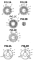
Specifically, referring to Fig. 2A, the EL device 22 which
emits white light is formed on the entire surface of the
transparent substrate 20 and is mounted on the illumination
substrate 21.
Referring to Fig. 2B, the EL device 22 is divided and
formed on the surface of the transparent substrate 20 with a
predetermined area, and is mounted on the illumination
substrate 21. The area of the EL element 22 is properly set
and, thus, the brightness is adjusted and the subject can be
illuminated with desired brightness.
The entire surface of the illumination substrate 21 may
be divided into a plurality of surfaces with a predetermined
area to form the EL device 22 and the desired surface of the
EL device 22 may properly emit light. Thus, the brightness
of illumination light can properly be changed in accordance
with the observing position in the body cavity through which
the capsule endoscope passes.
Further, the EL device 22 may directly be formed on the
illumination substrate 21. Alternatively, a condenser lens
or diffusion lens may be arranged on the EL device 22.
Referring to Figs. 2C and 2D, the EL device 22a having
the R, G, B matrixes is formed on the entire surface of the
illumination substrate 21. Or, referring to Fig. 2E, a red
EL device 22r, a green EL device 22g, and a blue EL device
22b are formed as three divided portions on the surface of
the illumination substrate 21 and are colored to white by
complementary colors. Then, white light-emission is
efficiently possible. Thus, a preferable observed image is
obtained.
The peripheral- circuit parts 8a, 8b, and 8c comprise
substrates 31, 32, and 33, and various electronic parts 34,
..., 40. The substrates 31 to 33 have wirings with
predetermined conductive patterns. The electronic parts 34
to 40 are mounted on the substrates 31 to 33. The
peripheral-circuit parts 8a to 8c are electrically and
mechanically connected by projecting electrodes 41. Thus,
various circuits such as a signal processing circuit, a
receiving and transmitting circuit, and a control circuit
are arranged in the capsule portion 2.
The signal processing circuit performs processing for
converting an optical image formed on the image pick-up
surface of the image pick-up element 13 into an image signal
and generates a driving signal for driving the image pick-up
element 13. The receiving and transmitting circuit performs
predetermined processing of the image signal generated by
the signal processing circuit, transmits the image signal to
the observation device as the external device (not shown),
and receives the control signal transmitted from the
observation device. The control circuit controls portions
based on various control signals received by the receiving
and transmitting circuit.
The power source unit 9 is, for example, a battery.
The power source unit 9 and the illumination unit 7 are
electrically connected by a flexible substrate 42. Further,
the power source unit 9 and the peripheral-circuit parts 8a
to 8c are electrically connected by the flexible substrate
42.
The power source unit 9 is not limited to the battery
and may be a power source unit or the like comprising a
power-receiving magnetic coil for receiving magnetic force
outputted from the external device (not shown) and a charge
capacitor.
A description is given of the operation of the capsule
endoscope 1 with the above-mentioned structure.
First, an examinee swallows the capsule endoscope 1.
Thus, the capsule endoscope 1 is introduced in the body
cavity via the mouth cavity.
Next, an operator operates the observation device and
transmits an observation instructing signal for endoscope
observation and the like to the capsule endoscope 1. Then,
the receiving and transmitting circuit in the capsule
endoscope 1 receives the observation instructing signal and
thus the EL device 22 in the illumination unit 7 enters the
light emitting state and the image pick-up element 13 in the
observation optical unit 6 enters the image pick-up state.
The illumination light without luminance blur obtained
by surface emission light by the EL device 22 uniformly
illuminates the subject. When the image pick-up element 13
is in the image pick-up state, the optical image of the
subject illuminated by the EL device 22 is formed on the
image pick-up surface of the image pick-up element 13 via
the observation side cover 4 and the optical lenses 11 and
12. The optical image formed on the image pick-up surface
is converted into an electric signal by the image pick-up
element 13. The converted electric signal is converted into
an image signal by the signal processing circuit. Then, the
converted image signal is transmitted to the observation
device via the receiving and transmitting circuit. The
image signal transmitted to the observation device is
outputted to a display device (not shown) in the observation
device. Consequently, an endoscope image captured by the
capsule endoscope 1 is displayed on a screen of the display
device.
As described above, the illumination unit in the
capsule endoscope is the surface emission light source
comprising the EL device containing a film on the surface of
the substrate. Therefore, the thickness dimension of the
capsule portion in the optical unit can considerably be
thinner in the longitudinal axis direction.
The EL device formed as the surface on the substrate as
the illumination unit in the capsule endoscope surface-emits
light. Thus, the uniform illumination light can be obtained
with excellent light-distribution and without luminance blur.
Further, the EL device forming the illumination unit in
the capsule endoscope has the property that no heat is
generated. Thus, it is possible to accurately prevent the
inconvenience that the heat generated by the illumination
unit is transmitted to the image pick-up element, the
temperature of the image pick-up element increases, and
noises generate. Further, the power consumption of the
illumination unit is considerably reduced.
With the above structure and operations, a preferable
endoscope image is obtained by the capsule endoscope.
Moreover, it is possible to effectively use the space in the
capsule portion forming the capsule endoscope, to reduce the
size of the capsule portion, and to effectively use power.
According to the first embodiment, the surface emission
light source comprises the EL device containing the film.
Further, the surface emission light source may comprise a
surface emission laser. As compared with the end surface
emission laser, the surface emission laser in this case can
be thinner. Furthermore, since the contact area to a
holding member is large, the surface emission laser has the
property that a cooling effect is high and a stable output
is obtained.
In the case of using the surface emission laser as the
surface emission light source, referring to Fig. 3A, a
plurality of surface emission lasers 25 which emits white
light at a predetermined position on the illumination
substrate 21 are arranged at predetermined positions.
Alternatively, referring to Fig. 3B, a surface emission red
laser 25r, a surface emission blue laser 25b, and a surface
emission green laser 25g are arranged at predetermined
positions on the illumination substrate 21. Thus, the white
light may be combined. A condenser lens or a diffusion lens
may be arranged onto the upper surface of the surface
emission laser.
As a result, the surface emission laser has preferable
light directivity and therefore the illumination light is
irradiated to a target position with stable brightness.
Referring to Figs. 4 to 7, a second embodiment of the
present invention is described.
The illumination substrate 21 is arranged at the
position approximately orthogonal to the capsule portion 2
in the longitudinal direction according to the first
embodiment. However, the surface emission light source
forming the illumination unit 7 arranged to the capsule
endoscope 1 may be arranged with the following structure.
That is, referring to Fig. 4, the illumination
substrate 21 having the EL device 22 and the electronic
parts 23 and 24 is arranged with the inclination having a
predetermined angle with respect to a longitudinal axis 2a
of the capsule portion 2.
Thus, the irradiation direction of the illumination
light emitted from the EL device 22 formed on the
illumination substrate 21 is properly set to a desired
direction.
Other structures are the same as those according to the
first embodiment, the same members are designated by the
same reference numerals, and a description thereof is
omitted.
As stated above, the illumination substrate forming the
illumination unit in the capsule endoscope is arranged with
the inclination of the predetermined angle with respect to
the longitudinal axis of the capsule portion. Consequently
the irradiation direction of the illumination light is
properly set matching the observing target, the illumination
efficiency is improved, and the brightness of the observing
region is set.
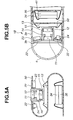
Referring to Fig. 5A, according to the second
embodiment, a flexible substrate 50 having the flexibility
is used in place of the illumination substrate 21 having the
EL device 22 and the electronic parts 23 and 24 and the
substrates 31 to 33 having the various electronic parts 34
to 40. Wiring patterns are formed on both the front and
back surfaces of the flexible substrate 50 with
predetermined shape.
The EL device 22 is directly formed at the
predetermined position of the flexible substrate 50. The
electronic parts 23 and 24, the image pick-up element 13,
and the electronic parts 34 to 40 are mounted on
predetermined positions by a flip chip, wire bonding or the
like in consideration that they are bent and arranged in the
main body 3.
Referring to Fig. 5B, a capsule endoscope 1B is formed
such that the flexible substrate 50 is bent like a ring in
the inner space of a main body 3a. A substrate supporting
portion 3b projected with a predetermined amount in the
circumferential direction is formed at a predetermined
position of the inner-peripheral surface of the main body 3a.
The substrate supporting portion 3b is used for setting the
edge portion of the flexible substrate 50 at a predetermined
state.
Therefore, by arranging the edge portion of the
flexible substrate 50 at the substrate supporting portion 3b,
the observation using the endoscope is performed by setting,
in a desired direction, the irradiation direction of the
illumination light emitted from the EL device 22 formed on
the flexible substrate 50.
Other structures are the same as those according to the
first embodiment, the same member is designated by the same
reference numeral, and a description thereof is omitted.
Prior to the electronic part 34, an electronic part 35
is electrically and mechanically connected to the flexible
substrate 50 via the projecting electrode 41 by using the
ultrasonic waves, thermal press, soldering or the like.
While the electronic part 34 is arranged on the electronic
part 35, the electronic part 34 is electronically and
mechanically connected to the flexible substrate 50 by using
the ultrasonic waves, thermal press, soldering, ACP, NCP or
the like. After connection, the connected peripheral
portion is fixed by a fixing agent of an epoxy system, a
phenol system, a silicon system, an acrylic system or the
like.
As mentioned above, the EL device is formed on the
flexible substrate and the electronic parts are mounted on
the flexible substrate. Thus, the number of assembling
processes and the number of parts are reduced.
By properly setting the position of the substrate
supporting portion formed on the main body, the irradiation
direction emitted from the EL device is set to the desired
direction.
Other operation and advantages are the same as those
according to the first embodiment.
Referring to Fig. 6A, in a capsule endoscope 1C
according to the second embodiment, the EL device 22 is
formed on a variable focusing member 60 as irradiation
direction changing means. A variable focusing member 60 is
arranged on an illumination substrate 21a.
The variable focusing member 60 mainly comprises a
bottom electrode 61, a top electrode 62, and a spacer member
63. The bottom electrode 61 is arranged onto the
illumination substrate 21a. The top electrode 62 faces the
bottom electrode 61 and is arranged thereto via the spacer
member 63. The spacer member 63 has a predetermined
electrostatic gap between the bottom electrode 61 and the
top electrode 63.
Specifically, referring to Fig. 6B, the top electrode
62 comprises: a first insulating resin film 62a and a second
insulating resin film 62b which are made of a polyimide
resin member or the like; and an electrode 62c made of an
aluminum sandwiched by the first and second insulating resin
films 62a and 62b. The EL device 22 is formed on the second
insulating resin film 62b.
A description is given of the operation for the EL
device 22 which is arranged to the variable focusing member
60 with the above-described structure.
An observation instructing signal is transmitted to the
capsule endoscope 1C, and a receiving and transmitting
circuit in the capsule endoscope 1C receives the observation
instructing signal. Thus, the EL device 22 of the
illumination unit 7 emits light and the image pick-up
element 13 of the observation optical unit 6 enters the
image pick-up state. Then, the EL device 22 outputs the
illumination light substantially in parallel with an optical
axis 6a of the observation optical unit 6.
Here, an observation device (not shown) transmits a
focusing change instructing signal to the capsule endoscope
1C. Then, the focusing position control circuit applies a
predetermined voltage to the bottom electrode 61 and the top
electrode 62. Then, an electric field is generated between
the electrodes, and the top electrode 62 is concave-bent.
This change inclines the illumination light outputted from
the EL device 22 to the optical axis 6a of the observation
optical unit 6. That is, the top electrode 62 is modified
in a predetermined state, thereby changing the output
direction of the illumination light outputted from the EL
device 22.
As mentioned above, the surface emission light source
is formed at the predetermined position of the variable
focusing member. Thereby, the focusing instructing signal
is outputted during the observation, the shape of the
variable focusing member is modified, and the output
direction of the illumination light outputted from the
surface emission light source can be changed to the desired
direction.
Thus, the optimum illumination light irradiates the
observing region and the preferable endoscope image is
obtained.
Other operation and advantages are the same as those
according to the first embodiment.
Referring to Fig. 7, in a capsule endoscope 1D
according to the second embodiment, the EL device 22 is
formed like a band or partly at a predetermined position out
of the observing field-of-view range shown by a broken line
of the observation optical unit 6 on the inner peripheral
surface of the observation side cover 4, instead of forming
the EL device 22 on the illumination substrate 21. The
electronic parts 23 and 24 forming the control circuit which
controls the light emitting state of the EL device 22 are
arranged on the edge surface side of the illumination
substrate 21.
Other structures are the same as those according to the
first embodiment, the same member is designated by the same
reference numeral, and a description thereof is omitted.
As mentioned above, the surface emission light source
formed by the film is formed at the predetermined position
on the inner surface of the observation side cover, and the
light-emitting control circuit parts are arranged on the
illumination substrate on the inner-surface side of the
observation cover. Thus, the space in the capsule portion
forming the capsule endoscope is effectively used or the
capsule portion is reduced in size.
Other operation and advantages are the same as those
according to the first embodiment.
As mentioned, the capsule endoscope having the
illumination unit formed of the surface emission light
source according to the present invention is superior in
luminance and in light-distribution, surely prevents the
thermal load from being applied to the image pick-up element
and is suitable to display an excellent endoscope image on a
display device.
Claims (15)
- A capsule endoscope characterized by comprising a capsule portion,
the capsule portion comprising at least:an observation optical unit having an image pick-up element and an optical lens that forms an objective optical system;an illumination unit having an illumination substrate, a surface emission light source, and a light-emitting control circuit;peripheral-circuit parts which form various circuits including a signal processing circuit, a receiving and transmitting circuit, and a control circuit; anda power source unit which supplies power to the observation optical unit, the illumination unit, and the peripheral-circuit part. - A capsule endoscope according to Claim 1, characterized in that the surface emission light source is arranged around the observation optical unit.
- A capsule endoscope according to Claim 1, characterized in that the surface emission light source is arranged on an inner surface of the capsule portion out of the filed of view of the objective optical system.
- A capsule endoscope according to Claim 1, characterized in that the surface emission light source is an electroluminescence device.
- A capsule endoscope according to Claim 1, characterized in that the surface emission light source is an organic light-emitting device containing a low-molecular-weight organic light-emitting material.
- A capsule endoscope according to Claim 1, characterized in that the surface emission light source is an organic light-emitting device containing a high-molecular-weight organic light-emitting material.
- A capsule endoscope according to Claim 1, characterized in that the surface emission light source is an inorganic light-emitting device containing an inorganic light-emitting material.
- A capsule endoscope according to Claim 1, characterized in that the surface emission light source is a surface emission laser diode.
- A capsule endoscope according to Claim 1, characterized in that the surface emission light source is formed as an R-, G-, and B-matrix.
- A capsule endoscope according to Claim 1, characterized in that the surface emission light source is divided and is arranged on the illumination substrate.
- A capsule endoscope according to Claim 10, characterized in that the surface emission light source is divided into sources for R, G, and B and is arranged.
- A capsule endoscope according to Claim 1, characterized in that the surface emission light source has an optical member for light condensing or diffusion on the top surface thereof.
- A capsule endoscope according to Claim 1, characterized in that the surface emission light source is arranged on a flexible substrate.
- A capsule endoscope according to Claim 4, further characterized by comprising:irradiation direction changing means for changing an irradiation direction of the surface emission light source on the illumination substrate.
- A capsule endoscope according to Claim 14, characterized in that the irradiation direction changing means comprises:a bottom electrode arranged on the illumination substrate;a top electrode arranged facing the bottom electrode; anda spacer member which forms a predetermined electrostatic gap between the bottom electrode and the top electrode.
Applications Claiming Priority (3)
| Application Number | Priority Date | Filing Date | Title |
|---|---|---|---|
| JP2003072665 | 2003-03-17 | ||
| JP2003072665A JP2004275542A (en) | 2003-03-17 | 2003-03-17 | Capsule endoscope |
| PCT/JP2004/003534 WO2004082470A1 (en) | 2003-03-17 | 2004-03-17 | Capsule type endoscope |
Publications (2)
| Publication Number | Publication Date |
|---|---|
| EP1604606A1 true EP1604606A1 (en) | 2005-12-14 |
| EP1604606A4 EP1604606A4 (en) | 2007-09-05 |
Family
ID=33027728
Family Applications (1)
| Application Number | Title | Priority Date | Filing Date |
|---|---|---|---|
| EP04721303A Withdrawn EP1604606A4 (en) | 2003-03-17 | 2004-03-17 | Capsule type endoscope |
Country Status (4)
| Country | Link |
|---|---|
| US (1) | US7229407B2 (en) |
| EP (1) | EP1604606A4 (en) |
| JP (1) | JP2004275542A (en) |
| WO (1) | WO2004082470A1 (en) |
Cited By (3)
| Publication number | Priority date | Publication date | Assignee | Title |
|---|---|---|---|---|
| WO2007129655A1 (en) | 2006-05-05 | 2007-11-15 | Olympus Medical Systems Corp. | Medical capsule |
| US8982200B2 (en) | 2009-10-27 | 2015-03-17 | Panasonic Healthcare Holdings Co., Ltd. | Intraoral camera with light collecting faces that deflect light close to an imaging window |
| US11435651B2 (en) | 2014-02-12 | 2022-09-06 | Semiconductor Energy Laboratory Co., Ltd. | Electronic device with flexible display and camera |
Families Citing this family (47)
| Publication number | Priority date | Publication date | Assignee | Title |
|---|---|---|---|---|
| ATE546086T1 (en) * | 2001-06-18 | 2012-03-15 | Given Imaging Ltd | IN VIVO SENSOR DEVICE HAVING A CIRCUIT BOARD COMPRISING RIGID AND FLEXIBLE SECTIONS |
| US7833151B2 (en) * | 2002-12-26 | 2010-11-16 | Given Imaging Ltd. | In vivo imaging device with two imagers |
| US20040199052A1 (en) | 2003-04-01 | 2004-10-07 | Scimed Life Systems, Inc. | Endoscopic imaging system |
| JP4550048B2 (en) * | 2003-05-01 | 2010-09-22 | ギブン イメージング リミテッド | Panorama field of view imaging device |
| US20050137459A1 (en) * | 2003-12-17 | 2005-06-23 | Scimed Life Systems, Inc. | Medical device with OLED illumination light source |
| EP2572626B1 (en) * | 2004-01-19 | 2016-03-23 | Olympus Corporation | Capsule type endoscope |
| JPWO2006001377A1 (en) * | 2004-06-28 | 2008-04-17 | オリンパス株式会社 | Endoscope device |
| US8500630B2 (en) * | 2004-06-30 | 2013-08-06 | Given Imaging Ltd. | In vivo device with flexible circuit board and method for assembly thereof |
| US20060015013A1 (en) * | 2004-06-30 | 2006-01-19 | Zvika Gilad | Device and method for in vivo illumination |
| WO2006003649A2 (en) * | 2004-06-30 | 2006-01-12 | Given Imaging Ltd. | Device and method for in-vivo illumination |
| CA2582292A1 (en) * | 2004-09-03 | 2006-03-09 | Stryker Gi Ltd. | Optical head for endoscope |
| US9033870B2 (en) * | 2004-09-24 | 2015-05-19 | Vivid Medical, Inc. | Pluggable vision module and portable display for endoscopy |
| US8858425B2 (en) * | 2004-09-24 | 2014-10-14 | Vivid Medical, Inc. | Disposable endoscope and portable display |
| US8878924B2 (en) * | 2004-09-24 | 2014-11-04 | Vivid Medical, Inc. | Disposable microscope and portable display |
| US8556806B2 (en) * | 2004-09-24 | 2013-10-15 | Vivid Medical, Inc. | Wavelength multiplexing endoscope |
| US8827899B2 (en) * | 2004-09-24 | 2014-09-09 | Vivid Medical, Inc. | Disposable endoscopic access device and portable display |
| US20060104057A1 (en) * | 2004-10-28 | 2006-05-18 | Jerome Avron | Device and method for in-vivo illumination |
| US20060224040A1 (en) * | 2005-03-31 | 2006-10-05 | Given Imaging Ltd. | In vivo imaging device and method of manufacture thereof |
| JP4528216B2 (en) * | 2005-06-29 | 2010-08-18 | オリンパスメディカルシステムズ株式会社 | Endoscope |
| US7896805B2 (en) * | 2005-11-23 | 2011-03-01 | Given Imaging Ltd. | In-vivo imaging device and optical system thereof |
| AU2006329540A1 (en) * | 2005-12-29 | 2007-07-05 | Given Imaging Ltd. | System device and method for estimating the size of an object in a body lumen |
| WO2007092108A2 (en) | 2006-02-07 | 2007-08-16 | Boston Scientific Limited | Medical device light source |
| JP5148068B2 (en) * | 2006-03-24 | 2013-02-20 | オリンパスメディカルシステムズ株式会社 | Endoscope |
| WO2007116204A1 (en) * | 2006-04-11 | 2007-10-18 | Iti Scotland Limited | Information extraction methods and apparatus including a computer-user interface |
| JP4574596B2 (en) * | 2006-07-06 | 2010-11-04 | 富士フイルム株式会社 | Capsule endoscope |
| CN101495022B (en) * | 2006-07-24 | 2011-09-07 | 皇家飞利浦电子股份有限公司 | Capsule camera with variable illumination of surrounding tissue |
| US7796870B2 (en) * | 2007-01-16 | 2010-09-14 | Capso Vision, Inc. | Lighting control for in vivo capsule camera |
| JP2009061097A (en) * | 2007-09-06 | 2009-03-26 | Olympus Medical Systems Corp | Capsule endoscope |
| JP5101387B2 (en) * | 2007-09-13 | 2012-12-19 | 富士フイルム株式会社 | Capsule endoscope |
| US20090076322A1 (en) * | 2007-09-13 | 2009-03-19 | Atsushi Matsunaga | Capsule endoscope |
| US9118850B2 (en) * | 2007-11-27 | 2015-08-25 | Capso Vision, Inc. | Camera system with multiple pixel arrays on a chip |
| KR100978559B1 (en) * | 2008-05-19 | 2010-08-27 | 주식회사 인트로메딕 | Capsule endoscope |
| JP2010005029A (en) * | 2008-06-25 | 2010-01-14 | Panasonic Electric Works Co Ltd | Medical light emitting plate |
| JP2010051461A (en) * | 2008-08-27 | 2010-03-11 | Olympus Corp | Endoscope |
| WO2010050426A1 (en) * | 2008-10-27 | 2010-05-06 | オリンパスメディカルシステムズ株式会社 | In vivo insertion device and medical system |
| US9621825B2 (en) * | 2008-11-25 | 2017-04-11 | Capsovision Inc | Camera system with multiple pixel arrays on a chip |
| WO2010092518A1 (en) * | 2009-02-12 | 2010-08-19 | Koninklijke Philips Electronics N.V. | Interventional instrument with illumination means |
| KR200446281Y1 (en) | 2009-04-27 | 2009-10-14 | 주식회사 인트로메딕 | Capsule Endoscope with Flexible Electronic Circuit Board |
| US8516691B2 (en) * | 2009-06-24 | 2013-08-27 | Given Imaging Ltd. | Method of assembly of an in vivo imaging device with a flexible circuit board |
| JP2013530187A (en) | 2010-06-17 | 2013-07-25 | ザ ユナイテッド ステイツ オブ アメリカ アズ リプレゼンティッド バイ ザ シークレタリー デパートメント オブ ヘルス アンド ヒューマン サービシーズ | Compositions and methods for treating inflammatory diseases. |
| CN103687646B (en) | 2011-03-17 | 2016-09-21 | 基文影像公司 | Capsule phototherapy |
| EP2641526A4 (en) * | 2011-04-18 | 2014-09-17 | Olympus Medical Systems Corp | OPTICAL MEASURING DEVICE, ENDOSCOPIC SYSTEM, AND OPTICAL MEASURING PROGRAM |
| US9380928B2 (en) * | 2011-06-06 | 2016-07-05 | Fujikura Ltd. | Structure of imaging part in electronic visualized catheter |
| EP2638845B1 (en) * | 2012-03-13 | 2016-01-06 | Panasonic Corporation | Endoscope camera |
| JP6469392B2 (en) * | 2013-09-11 | 2019-02-13 | 株式会社半導体エネルギー研究所 | Endoscope device |
| US10394012B2 (en) | 2016-04-01 | 2019-08-27 | INTHESMART Inc. | Endoscopy system |
| KR101828348B1 (en) * | 2016-04-01 | 2018-03-22 | 인더스마트 주식회사 | Endoscopy system |
Family Cites Families (24)
| Publication number | Priority date | Publication date | Assignee | Title |
|---|---|---|---|---|
| US3417745A (en) * | 1963-08-23 | 1968-12-24 | Sheldon Edward Emanuel | Fiber endoscope provided with focusing means and electroluminescent means |
| JPS4845187A (en) * | 1971-10-11 | 1973-06-28 | ||
| JPS5846863B2 (en) * | 1977-08-25 | 1983-10-19 | 松下電器産業株式会社 | Semiconductor integrated circuit device |
| FR2690066B1 (en) * | 1992-04-21 | 1998-08-07 | Jean Marc Inglese | IMAGE ACQUISITION DEVICE USING A SEMICONDUCTOR LIGHT SOURCE |
| JPH08117184A (en) | 1994-10-28 | 1996-05-14 | Matsushita Electric Ind Co Ltd | Endoscope device |
| US5825796A (en) * | 1996-09-25 | 1998-10-20 | Picolight Incorporated | Extended wavelength strained layer lasers having strain compensated layers |
| JP3935550B2 (en) | 1997-03-21 | 2007-06-27 | オリンパス株式会社 | Tubular observation device |
| US7038398B1 (en) * | 1997-08-26 | 2006-05-02 | Color Kinetics, Incorporated | Kinetic illumination system and methods |
| JPH11253398A (en) | 1998-03-16 | 1999-09-21 | Olympus Optical Co Ltd | Electronic endoscope device |
| US8636648B2 (en) * | 1999-03-01 | 2014-01-28 | West View Research, Llc | Endoscopic smart probe |
| JP2001091860A (en) | 1999-09-22 | 2001-04-06 | Asahi Optical Co Ltd | Capsule endoscope |
| US7039453B2 (en) * | 2000-02-08 | 2006-05-02 | Tarun Mullick | Miniature ingestible capsule |
| US6670599B2 (en) * | 2000-03-27 | 2003-12-30 | Aegis Semiconductor, Inc. | Semitransparent optical detector on a flexible substrate and method of making |
| US6860648B2 (en) * | 2000-06-30 | 2005-03-01 | Opti Japan Corporation | Multi channel optical transmitter/receiver module and manufacturing method thereof |
| US6788467B2 (en) * | 2000-12-15 | 2004-09-07 | Seiko Epson Corporation | Electro-optical device having reduced size and improved light utilization efficiency and electronic using the same |
| ATE546086T1 (en) * | 2001-06-18 | 2012-03-15 | Given Imaging Ltd | IN VIVO SENSOR DEVICE HAVING A CIRCUIT BOARD COMPRISING RIGID AND FLEXIBLE SECTIONS |
| US7347817B2 (en) * | 2001-08-02 | 2008-03-25 | Given Imaging Ltd. | Polarized in vivo imaging device, system and method |
| US20030028078A1 (en) * | 2001-08-02 | 2003-02-06 | Arkady Glukhovsky | In vivo imaging device, system and method |
| US8423110B2 (en) * | 2002-01-09 | 2013-04-16 | Boston Scientific Scimed, Inc. | Imaging device and related methods |
| JP2003295112A (en) * | 2002-04-05 | 2003-10-15 | Canon Inc | Scanning image display optical system, scanning image display device, and image display system |
| US6653654B1 (en) * | 2002-05-01 | 2003-11-25 | The University Of Hong Kong | Electroluminescent materials |
| KR100483986B1 (en) * | 2002-06-20 | 2005-04-15 | 삼성에스디아이 주식회사 | Organic polymer electroluminescent display device using phosphresecnce mixture as emiting material |
| US7473218B2 (en) * | 2002-08-06 | 2009-01-06 | Olympus Corporation | Assembling method of capsule medical apparatus |
| WO2004028336A2 (en) * | 2002-09-30 | 2004-04-08 | Given Imaging Ltd. | Reduced size imaging device |
-
2003
- 2003-03-17 JP JP2003072665A patent/JP2004275542A/en active Pending
-
2004
- 2004-03-12 US US10/799,796 patent/US7229407B2/en not_active Expired - Lifetime
- 2004-03-17 WO PCT/JP2004/003534 patent/WO2004082470A1/en not_active Ceased
- 2004-03-17 EP EP04721303A patent/EP1604606A4/en not_active Withdrawn
Cited By (4)
| Publication number | Priority date | Publication date | Assignee | Title |
|---|---|---|---|---|
| WO2007129655A1 (en) | 2006-05-05 | 2007-11-15 | Olympus Medical Systems Corp. | Medical capsule |
| US8982200B2 (en) | 2009-10-27 | 2015-03-17 | Panasonic Healthcare Holdings Co., Ltd. | Intraoral camera with light collecting faces that deflect light close to an imaging window |
| US11435651B2 (en) | 2014-02-12 | 2022-09-06 | Semiconductor Energy Laboratory Co., Ltd. | Electronic device with flexible display and camera |
| US12535719B2 (en) | 2014-02-12 | 2026-01-27 | Semiconductor Energy Laboratory Co., Ltd. | Electronic device with foldable display |
Also Published As
| Publication number | Publication date |
|---|---|
| WO2004082470A1 (en) | 2004-09-30 |
| US7229407B2 (en) | 2007-06-12 |
| JP2004275542A (en) | 2004-10-07 |
| EP1604606A4 (en) | 2007-09-05 |
| US20050043586A1 (en) | 2005-02-24 |
Similar Documents
| Publication | Publication Date | Title |
|---|---|---|
| US7229407B2 (en) | Capsule endoscope with electroluminescence light source | |
| US7465271B2 (en) | Capsule endoscope | |
| EP2572626B1 (en) | Capsule type endoscope | |
| JPH11267099A (en) | Endoscope | |
| US20060149132A1 (en) | Device and method for in vivo illumination | |
| US7585275B2 (en) | Capsule endoscope | |
| JP2003260025A (en) | Capsule endoscope | |
| JP7227011B2 (en) | Endoscope | |
| US9439559B2 (en) | Image pickup apparatus and electronic device using the same | |
| JP2005205077A (en) | Capsule type endoscope | |
| JP5063834B2 (en) | Electronic endoscope system | |
| JPH11290269A (en) | Solid-state imaging device | |
| WO2020067219A1 (en) | Angled viewing endoscope | |
| US20050074233A1 (en) | Lighting apparatus for photographing | |
| US20150346586A1 (en) | Light emitting diode packaging structure and camera module using the same | |
| JPS63313970A (en) | Solid-state image pickup device | |
| KR100978559B1 (en) | Capsule endoscope | |
| JP2004065575A (en) | Capsule type endoscope and assembling method therefor | |
| US20240008718A1 (en) | Image pickup unit and endoscope | |
| CN217548001U (en) | Capsule endoscope and capsule endoscope system | |
| JP2008237916A (en) | Solid-state imaging device and endoscope unit with it | |
| JP2006255247A (en) | Capsule endoscope | |
| TWI563960B (en) | Endoscope apparatus with wafer level lens | |
| JP2005027723A (en) | Camera in body cavity | |
| JP4533635B2 (en) | Method for manufacturing capsule medical device |
Legal Events
| Date | Code | Title | Description |
|---|---|---|---|
| PUAI | Public reference made under article 153(3) epc to a published international application that has entered the european phase |
Free format text: ORIGINAL CODE: 0009012 |
|
| 17P | Request for examination filed |
Effective date: 20050916 |
|
| AK | Designated contracting states |
Kind code of ref document: A1 Designated state(s): AT BE BG CH CY CZ DE DK EE ES FI FR GB GR HU IE IT LI LU MC NL PL PT RO SE SI SK TR |
|
| AX | Request for extension of the european patent |
Extension state: AL LT LV MK |
|
| DAX | Request for extension of the european patent (deleted) | ||
| RBV | Designated contracting states (corrected) |
Designated state(s): DE FR GB |
|
| A4 | Supplementary search report drawn up and despatched |
Effective date: 20070803 |
|
| STAA | Information on the status of an ep patent application or granted ep patent |
Free format text: STATUS: THE APPLICATION HAS BEEN WITHDRAWN |
|
| 18W | Application withdrawn |
Effective date: 20071218 |