EP1603490B1 - Platzierungsvorrichtung für eine prothese auf einer körperröhre - Google Patents
Platzierungsvorrichtung für eine prothese auf einer körperröhre Download PDFInfo
- Publication number
- EP1603490B1 EP1603490B1 EP04721566A EP04721566A EP1603490B1 EP 1603490 B1 EP1603490 B1 EP 1603490B1 EP 04721566 A EP04721566 A EP 04721566A EP 04721566 A EP04721566 A EP 04721566A EP 1603490 B1 EP1603490 B1 EP 1603490B1
- Authority
- EP
- European Patent Office
- Prior art keywords
- tubing
- helical
- amplitude
- wall
- flow
- Prior art date
- Legal status (The legal status is an assumption and is not a legal conclusion. Google has not performed a legal analysis and makes no representation as to the accuracy of the status listed.)
- Expired - Lifetime
Links
- 210000001124 body fluid Anatomy 0.000 title claims abstract description 14
- 239000010839 body fluid Substances 0.000 title claims abstract description 14
- 239000000463 material Substances 0.000 claims description 22
- 239000008016 pharmaceutical coating Substances 0.000 claims description 2
- 238000000034 method Methods 0.000 description 33
- 238000004519 manufacturing process Methods 0.000 description 24
- 210000004204 blood vessel Anatomy 0.000 description 14
- 229920001187 thermosetting polymer Polymers 0.000 description 14
- 210000001367 artery Anatomy 0.000 description 12
- 230000009467 reduction Effects 0.000 description 10
- 230000002792 vascular Effects 0.000 description 10
- 238000011161 development Methods 0.000 description 9
- 239000012530 fluid Substances 0.000 description 9
- 230000002787 reinforcement Effects 0.000 description 9
- 230000000694 effects Effects 0.000 description 8
- 229920000295 expanded polytetrafluoroethylene Polymers 0.000 description 8
- 238000004804 winding Methods 0.000 description 8
- 230000017531 blood circulation Effects 0.000 description 7
- 238000002474 experimental method Methods 0.000 description 7
- 206010020718 hyperplasia Diseases 0.000 description 7
- 210000003462 vein Anatomy 0.000 description 7
- -1 polypropylene Polymers 0.000 description 6
- 230000008569 process Effects 0.000 description 6
- 230000008093 supporting effect Effects 0.000 description 6
- 238000002156 mixing Methods 0.000 description 5
- 230000007170 pathology Effects 0.000 description 5
- XLYOFNOQVPJJNP-UHFFFAOYSA-N water Substances O XLYOFNOQVPJJNP-UHFFFAOYSA-N 0.000 description 5
- 239000004743 Polypropylene Substances 0.000 description 4
- 230000009286 beneficial effect Effects 0.000 description 4
- 210000004369 blood Anatomy 0.000 description 4
- 239000008280 blood Substances 0.000 description 4
- 238000010438 heat treatment Methods 0.000 description 4
- 238000003780 insertion Methods 0.000 description 4
- 230000037431 insertion Effects 0.000 description 4
- 239000004033 plastic Substances 0.000 description 4
- 229920003023 plastic Polymers 0.000 description 4
- 229920000728 polyester Polymers 0.000 description 4
- 239000005020 polyethylene terephthalate Substances 0.000 description 4
- 229920001155 polypropylene Polymers 0.000 description 4
- 230000002829 reductive effect Effects 0.000 description 4
- 238000000926 separation method Methods 0.000 description 4
- 229910000831 Steel Inorganic materials 0.000 description 3
- 230000001464 adherent effect Effects 0.000 description 3
- 230000004872 arterial blood pressure Effects 0.000 description 3
- 230000008901 benefit Effects 0.000 description 3
- 239000000560 biocompatible material Substances 0.000 description 3
- 238000001816 cooling Methods 0.000 description 3
- 238000013461 design Methods 0.000 description 3
- 238000011068 loading method Methods 0.000 description 3
- 239000004800 polyvinyl chloride Substances 0.000 description 3
- 230000000717 retained effect Effects 0.000 description 3
- 239000010959 steel Substances 0.000 description 3
- 208000019553 vascular disease Diseases 0.000 description 3
- 201000001320 Atherosclerosis Diseases 0.000 description 2
- 229920004934 Dacron® Polymers 0.000 description 2
- 208000007536 Thrombosis Diseases 0.000 description 2
- 229920000249 biocompatible polymer Polymers 0.000 description 2
- 230000004087 circulation Effects 0.000 description 2
- 239000007799 cork Substances 0.000 description 2
- 238000000502 dialysis Methods 0.000 description 2
- 201000010099 disease Diseases 0.000 description 2
- 208000037265 diseases, disorders, signs and symptoms Diseases 0.000 description 2
- 230000002349 favourable effect Effects 0.000 description 2
- 238000007654 immersion Methods 0.000 description 2
- 230000002401 inhibitory effect Effects 0.000 description 2
- 238000002844 melting Methods 0.000 description 2
- 230000008018 melting Effects 0.000 description 2
- 239000002184 metal Substances 0.000 description 2
- 229910052751 metal Inorganic materials 0.000 description 2
- 229920000139 polyethylene terephthalate Polymers 0.000 description 2
- 229920000915 polyvinyl chloride Polymers 0.000 description 2
- 230000000541 pulsatile effect Effects 0.000 description 2
- 230000000284 resting effect Effects 0.000 description 2
- 230000008321 arterial blood flow Effects 0.000 description 1
- 238000005452 bending Methods 0.000 description 1
- 210000000013 bile duct Anatomy 0.000 description 1
- 239000013060 biological fluid Substances 0.000 description 1
- 210000000601 blood cell Anatomy 0.000 description 1
- 230000036772 blood pressure Effects 0.000 description 1
- 230000008859 change Effects 0.000 description 1
- 239000011248 coating agent Substances 0.000 description 1
- 238000000576 coating method Methods 0.000 description 1
- 230000000295 complement effect Effects 0.000 description 1
- 239000002131 composite material Substances 0.000 description 1
- 238000010276 construction Methods 0.000 description 1
- 238000010924 continuous production Methods 0.000 description 1
- 230000008602 contraction Effects 0.000 description 1
- 210000004351 coronary vessel Anatomy 0.000 description 1
- 230000003247 decreasing effect Effects 0.000 description 1
- 238000006073 displacement reaction Methods 0.000 description 1
- 238000009826 distribution Methods 0.000 description 1
- 230000009977 dual effect Effects 0.000 description 1
- 230000002526 effect on cardiovascular system Effects 0.000 description 1
- 238000011010 flushing procedure Methods 0.000 description 1
- 230000002496 gastric effect Effects 0.000 description 1
- 239000003292 glue Substances 0.000 description 1
- 230000001976 improved effect Effects 0.000 description 1
- 238000001727 in vivo Methods 0.000 description 1
- 238000011221 initial treatment Methods 0.000 description 1
- 238000002347 injection Methods 0.000 description 1
- 239000007924 injection Substances 0.000 description 1
- 230000002452 interceptive effect Effects 0.000 description 1
- 210000003127 knee Anatomy 0.000 description 1
- 238000005461 lubrication Methods 0.000 description 1
- 210000004072 lung Anatomy 0.000 description 1
- 238000003754 machining Methods 0.000 description 1
- 230000014759 maintenance of location Effects 0.000 description 1
- 239000012528 membrane Substances 0.000 description 1
- 238000003801 milling Methods 0.000 description 1
- 210000000277 pancreatic duct Anatomy 0.000 description 1
- 230000004962 physiological condition Effects 0.000 description 1
- 238000003672 processing method Methods 0.000 description 1
- 230000001737 promoting effect Effects 0.000 description 1
- 230000003014 reinforcing effect Effects 0.000 description 1
- 210000002254 renal artery Anatomy 0.000 description 1
- 238000009877 rendering Methods 0.000 description 1
- 239000011347 resin Substances 0.000 description 1
- 229920005989 resin Polymers 0.000 description 1
- 210000002345 respiratory system Anatomy 0.000 description 1
- 230000004044 response Effects 0.000 description 1
- 229920002379 silicone rubber Polymers 0.000 description 1
- 239000004945 silicone rubber Substances 0.000 description 1
- 229910000679 solder Inorganic materials 0.000 description 1
- 239000007787 solid Substances 0.000 description 1
- 238000013268 sustained release Methods 0.000 description 1
- 239000012730 sustained-release form Substances 0.000 description 1
- 229920002994 synthetic fiber Polymers 0.000 description 1
- 238000012360 testing method Methods 0.000 description 1
- 230000001225 therapeutic effect Effects 0.000 description 1
- 238000009827 uniform distribution Methods 0.000 description 1
- 210000000626 ureter Anatomy 0.000 description 1
- 210000003708 urethra Anatomy 0.000 description 1
Images


Classifications
-
- A—HUMAN NECESSITIES
- A61—MEDICAL OR VETERINARY SCIENCE; HYGIENE
- A61F—FILTERS IMPLANTABLE INTO BLOOD VESSELS; PROSTHESES; DEVICES PROVIDING PATENCY TO, OR PREVENTING COLLAPSING OF, TUBULAR STRUCTURES OF THE BODY, e.g. STENTS; ORTHOPAEDIC, NURSING OR CONTRACEPTIVE DEVICES; FOMENTATION; TREATMENT OR PROTECTION OF EYES OR EARS; BANDAGES, DRESSINGS OR ABSORBENT PADS; FIRST-AID KITS
- A61F2/00—Filters implantable into blood vessels; Prostheses, i.e. artificial substitutes or replacements for parts of the body; Appliances for connecting them with the body; Devices providing patency to, or preventing collapsing of, tubular structures of the body, e.g. stents
- A61F2/02—Prostheses implantable into the body
- A61F2/04—Hollow or tubular parts of organs, e.g. bladders, tracheae, bronchi or bile ducts
- A61F2/06—Blood vessels
- A61F2002/068—Modifying the blood flow model, e.g. by diffuser or deflector
Definitions
- This invention relates to devices for placement externally of a body fluid flow conduit, such as external stents or sheaths.
- a vascular prosthesis comprising a length of generally hollow tubing having openings at both ends thereof and including a non-planar curved portion so as to induce swirl flow in blood flowing through the curved portion.
- the swirl flow induced by skewing of the blood flow within the non-planar curved portion improves flow characteristics and reduces the potential for vascular disease including intimal hyperplasia.
- a stent for supporting part of a blood vessel.
- the stent includes a supporting portion around which or within which part of a blood vessel intended for grafting can be placed so that the stent internally or externally supports that part.
- the supporting portion of the stent is shaped so that flow between graft and host vessel is caused to follow a non-planar curve. This generates a swirl flow, again to provide a favourable blood flow velocity pattern which reduces the occurrence of vascular disease, particularly intimal hyperplasia.
- a stent in this case including a supporting portion around which or within which part of an intact blood vessel other than a graft can be placed.
- This supporting portion can prevent failure of the vessel through blockage, kinking or collapse.
- the supporting portion of the stent is of a shape and/or orientation whereby flow within the vessel is caused to follow a non-planar curve.
- Favourable blood flow velocity patterns can be achieved through generation therein of swirl flow within and beyond the stent. Failures in blood vessels through diseases such as thrombosis, atherosclerosis, intimal hyperplasia can be significantly reduced.
- the artificial or modified natural blood flow tubing is helical or part-helical.
- the prosthesis or the supported vessel may undergo less than one complete turn of a helix, for example less than one half or less than one quarter of such a turn.
- the "swept width" of a helix means the outer width of the helix when viewed axially of the helix. In cases where this swept width is relatively wide compared to the width of the tubing itself, the prosthesis or stent may be more bulky than is necessary or acceptable to induce the required swirl flow.
- a further proposal in WO 00/38591 is to provide a circular-section tube bent into a cork screw shape. It is usual for the helix of a cork screw to have a clear gap down the middle, so that this proposed configuration would have a wide swept width compared to the width of the tubing, certainly more than two tubing diameters. The amplitude of the helix would be greater than one half of the internal diameter of the tubing and there would be no "line of sight" along the inside of the tubing. This proposal would therefore be relatively bulky and unsuitable for certain applications.
- a similar proposal is shown in Figure 5 of WO 02/98325 , the tubing having a helix with a large amplitude and again no "line of sight" along the inside of the tubing.
- FR2248015 discloses a surgically implantable conduit for the flow of biological fluids comprising a tubing portion with a wall defining a longitudinally extending cavity, the longitudinal cavity of said tubing portion being substantially free of ribs or grooves, wherein the centre line of the longitudinal cavity follows a substantially helical path with a helix angle less than or equal to 65°, and wherein the amplitude of the helix is less than or equal to one half of the internal diameter of the tubing portion.
- a device for placement externally of a body fluid flow conduit comprising a tubing portion with a wall defining a longitudinally extending cavity for receiving the conduit, the longitudinal cavity of said tubing portion being substantially free of ribs or grooves, wherein the centre line of the longitudinal cavity follows a substantially helical path with a helix angle less than or equal to 65°, characterised in that the amplitude of the helix is less than or equal to one half of the internal diameter of the tubing portion, and in that the wall has a helical portion extending longitudinally and circumferentiallly and which has a lower extensibility as compared to adjacent portions of the tubing portion wall.
- Certain preferred embodiments are concerned with devices for placement around artificial or natural tubing of the human or animal body, more particularly artificial or natural tubing for blood flow.
- the invention is particularly suitable for in vivo tubing, stents or sheaths external to intact blood vessels or blood vessels intended for grafting.
- the tubing acts as an external sheath to create or maintain helical geometry in a flexible conduit, which may itself be artificial but is preferably a natural vessel, more preferably an intact blood vessel or a blood vessel intended for grafting.
- the external sheath preferably fits loosely round the flexible conduit, so that the flexible conduit is not significantly restricted when expanding under internal pressurisation.
- the helical geometry may be imposed on the flexible conduit by the tubing without requiring a tight fit, providing the amplitude of the tubing helical centre line is sufficiently large. This is in contrast to the proposals discussed above having helical ribs or twisted non-circular cross-sections, in which a tight fit is needed in order to impose their geometry on the wall of the contained conduit.
- a loose fit as preferred in the present invention, may be beneficial in preventing the development of intimal hyperplasia, as discussed by V. Vijayan et al., in Eur J Vasc Endovasc Surg 24, 13-22 (2002 ).
- a loose fit may involve the inner diameter of the external sheath being a few millimetres larger than the diameter of the expanded fluid conduit, preferably about 3-6 mm larger.
- the device according to the invention improves flow characteristics in the conduit.
- near wall velocities are very low compared to velocities at the core of the tube, due to the effects of viscosity.
- speed of the flow at the outside of the bend is increased but the speed of the flow at the inside is retarded further. In both cases, there is considerable variation in axial velocity across the width of the tube.
- a swirl flow is generated and the axial velocity profile of the flow across the tubing portion becomes generally more uniform or "blunter", with the axial velocity of flow at both the outside and inside of the tubing portion being closer to the mean axial velocity.
- the flow characteristics are improved by causing swirling and a relatively uniform distribution of axial and near wall velocity.
- Mixing over the cross section is also promoted and there is a reduction in the likelihood of occurrence of flow instability.
- the avoidance and flushing of stagnant zones is assisted.
- the amplitude of the helix refers to the extent of displacement from a mean position to a lateral extreme. So, in the case of the tubing having a helical centre line, the amplitude is one half of the full lateral width of the helical centre line.
- the amplitude of the helix is less than or equal to one half of the internal diameter of the tubing
- there is a "line of sight" along the lumen of the tubing unlike in the case of a corkscrew configuration where in effect the helix is wound around a core (either solid, or "virtual" with a core of air).
- the term "relative amplitude" of a helical tubing is regarded as the amplitude divided by the internal diameter. So, in the tubing of the first aspect of the invention in which the amplitude of the helical tubing is less than or equal to one half of the internal diameter of the tubing, this means that the relative amplitude is less than or equal to 0.5. Relative amplitudes less than or equal to 0.45, 0.4, 0.35, 0.3, 0.25, 0.2, 0.15 or 0.1 may be preferred in some circumstances. It is however preferred for the relative amplitude to be at least 0.05, more preferably 0.1. This can help to ensure that the desired swirl flow is induced.
- the relative amplitude may vary according to the use of the device and the spatial constraints on its design. It will however be appreciated that by keeping the amplitude less than half the tubing portion internal diameter a swirling flow may be induced without creating an excessively large device.
- the "envelope" occupied by the device can fit into the space available in the surrounding tissue, and even if this envelope is caused to follow a particular path by the local environment in which the device is located, the desired helical geometry of the flow lumen of the conduit can be maintained.
- the angle of the helix is also a relevant factor in balancing the space constraints on the flow tubing with the desirability of maximising the cross-sectional area available for flow.
- the helix angle is less than or equal to 65°, preferably less than or equal to 55°, 45°, 35°, 25°, 20°, 15°, 10° or 5°.
- the helix angle may be optimized according to the conditions: viscosity, density and velocity of fluid.
- the helix angle may be smaller whilst satisfactory swirl flow is achieved, whilst with lower Reynolds numbers a higher helix angle will be required to produce satisfactory swirl.
- the use of higher helix angles will generally be undesirable, as there may be near wall pockets of stagnant fluid. Therefore, for a given Reynolds number (or range of Reynolds numbers), the helix angle will preferably be chosen to be as low as possible to produce satisfactory swirl. Lower helix angles result in smaller increases in length as compared to that of the equivalent cylindrical tubing. In certain embodiments, the helix angle is less than 20° or less than 15°.
- the tubing portion may be made with substantially the same relative amplitude and helix angle along its length. There may be small variations when the tubing is in use, caused by elongation or contraction of the tubing portion due to tensile loading or caused by torsional loading. However, there may be circumstances in which the tubing portion has a variable helix angle and/or relative amplitude, either to suit the space constraints or to optimise the flow conditions.
- the tubing portion may have a substantially constant cross-sectional area along its length. Again, there may be variations in use caused by loading on the tubing portion.
- the helical tubing portion may form just part of the overall length of tubing or it may extend over substantially its entire length.
- a device may have a tubing portion with the geometry of the invention over part of its length or over substantially its entire length.
- the helical tubing portion may undergo a fraction of one complete turn, for example one quarter, one half or three quarters of a turn.
- the helical tubing portion undergoes at least one turn, more preferably at least a plurality of turns. Repeated turns of the helix along the tubing portion will tend to ensure that the swirl flow is generated and maintained.
- the tubing portion may extend generally linearly.
- the axis about which the centre line of the tubing portion follows a substantially helical path may be straight.
- the axis may itself be curved, whereby the envelope occupied by the tubing is curved, for example to produce an "arch" shaped tubing.
- the bend of the arch may be planar or non-planar, but should preferably be such that swirl is maintained and not cancelled by the geometry of the bend.
- a device may be generally "arch" shaped (planar or non-planar), having the geometry in accordance with the first aspect of the invention, i.e. being in the form of a tubing portion following a substantially helical path with a helix angle less than or equal to 65°, and with an amplitude less than or equal to one half of the internal diameter of the tubing portion.
- the device may if desired comprise a pharmaceutical coating.
- a coating could be provided to provide sustained release of the pharmaceutical over a period of time. So, the blood flow tubing could provide a pharmaceutical for initial treatment of a disease, and in the longer term the tubing portion gives a therapeutic benefit due to the characteristics which it imparts to the flow.
- the centre line of the tubing is also straight.
- the tubing portion of the invention may have a circular cross-section and thus allow the conduit to have the smallest possible wetted perimeter to cross-sectional area ratio, whilst still having the necessary characteristics to induce swirl flow.
- the tubing portion of the present invention has a non-circular cross-section, for example to assist interfacing or where pressure loss considerations are not significant.
- the tubing has a single internal rib arranged helically. This results in the tubing having a centre line which follows a helical path, but because the rib is provided in an otherwise cylindrical tube, the amplitude of the helix is very small, generally having a relative amplitude appreciably less than 0.05.
- the generation of swirl flow, if there is any, is correspondingly limited and unsatisfactory.
- the tubing portion of the invention has a helical centre line, there is, in the conduit around which the device is placed, spatial reorganisation of vortical structures, which results in motion of the core or cores of the axial flow across the section of the tubing portion, promoting mixing across the cross section.
- the swirl inhibits the development of stagnation and flow separation regions and stabilises flows.
- the centre line is straight, not helical. Whilst this can be expected to stabilise flow at sharp bends, it does not in straight tubes cause spatial reorganisation of vortical structures, resulting in motion of the core or cores of the axial flow across the section of the tube. Thus it does not promote mixing across the cross section to the same extent as tubing according to the invention. Such mixing may be important in maintaining the mass transport and physiological integrity of the blood vessels.
- a device for placement externally of a body fluid flow conduit comprising a tubing portion defining a longitudinally extending cavity for receiving the conduit, wherein the centre line of the longitudinal cavity follows a substantially helical path with a helix angle less than or equal to 65°, wherein the amplitude of the helical centre line is less than or equal to one half of the internal diameter of the tubing portion, and wherein the amplitude of the helical centre line is more than or equal to 0.05 of the internal diameter of the tubing portion.
- the tubing geometry disclosed herein may be used in various biomedical applications e.g. in various arteries (such as in the coronary and renal arteries), in veins, and in non-cardiovascular applications such as in the gastro-intestinal (e.g. bile or pancreatic ducts), genito-urinary (e.g. ureter or urethra) or the respiratory system (lung airways).
- the invention extends to devices for placement around flow conduits for the flow of body fluids other than blood.
- the use of the tubing geometry of the invention can avoid the presence of stagnant regions, and hence be beneficial.
- tubing is made from flexible material, such as synthetic fabric, but rather than being formed as a cylinder is instead formed so that its centre line follows a substantially helical path, it is in some circumstances capable of "straightening out", involving a reduction in the amplitude of the helix and a corresponding increase in the pitch of the helix and in the length of the tubing (i.e. axial extension).
- the benefits of swirl flow discussed above may then be reduced or lost.
- a device for placement externally of a body fluid flow conduit having a tubing portion comprising a wall defining a longitudinally extending cavity for receiving the conduit, the longitudinal cavity being substantially free of ribs or grooves, the longitudinal cavity having a centre line following a substantially helical path, and the wall having a helical portion extending longitudinally and circumferentially so as to resist reduction of the amplitude of the helical centre line.
- a helical portion according to this example can therefore help to maintain the desired amplitude of the helical centre line, and hence maintain the desired swirl fluid flow characteristics.
- the helical portion will have a lower extensibility as compared to adjacent portions of the tubing. It will normally have the same pitch as the helical centre line of the longitudinal cavity of the tubing portion so as to conform therewith.
- the helical portion may be thicker in the radial direction than adjacent portions of the tubing wall. This is a way of achieving the result of the helical portion having lower extensibility than the adjacent portions.
- the helical portion may be made from a material different from that of adjacent portions of the tubing wall.
- the amplitude of the helical centre line of the tubing longitudinal cavity may be less than or equal to one half of the internal diameter of the tubing. It is expected that any straightening out of the tubing, and hence reduction in the relative amplitude, when the tubing is in use will not be significant, because of the presence of the helical portion.
- the device may be desired to split the device axially, for example when it is applied to an intact blood vessel or a blood vessel being used in a bypass graft procedure, enabling the vessel to be inserted sideways through the split rather than being fed longitudinally from one end to the other.
- the tubing portion could then be reconstituted with the conduit (i.e. vessel) contained within it by some fastening procedure, or for example by means of surgical sutures.
- the invention extends to external stents of helical form.
- This type of stent is implanted over a venous arterial or prosthetic graft or intact blood vessel to cause the geometrical configuration of the graft or vessel, e.g. artery, to adopt a predetermined form to promote swirl flow.
- External stents may for example be made of a thermosettable plastic, biodegradable material, or a supported synthetic woven material, in the form of a hollow tube, the walls of which contain numerous openings, or have a micro- or macro-porosity, so that the exterior of the graft or vein is not fully shielded.
- Also disclosed herein is a method of making a device for placement externally of a body fluid flow cavity, the method comprising positioning a generally tubular, flexible wall adjacent to a further flexible member, twisting the tubular flexible wall and the flexible member around each other, and causing the tubular flexible wall to retain, at least partly, the twisted shape.
- the amplitude of the twisted tubular wall can be kept desirably small, so as to form tubing without excessive lateral bulk. If the tubular wall were instead twisted round a rigid member, then it would adopt a corkscrew configuration, in effect a helix round a core provided by the rigid member. If the tubular wall retained that shape when the rigid member is removed, it would then have a core of air and be laterally bulky.
- the tubular wall formed by twisting round a flexible member will define a longitudinally extending cavity having a centre line following a substantially helical path.
- the relative amplitude of helical tubing formed by the method discussed is preferably less than or equal to 0.5. It may however be preferred for the relative amplitude of the helical tubing to be greater than 0.5, because if the tubular wall fits loosely over a conduit (as discussed previously) the relative amplitude for the conduit itself is likely to be less than that of the helical tubing.
- the relative amplitude of the helical tubing may for example be 0.6 or 0.7 or more. Generally, the tubing may have relative amplitudes, helix angles, cross-sectional shapes, number of turns etcetera as discussed above in relation to the other examples and aspects of the invention.
- the tubular wall may be reinforced to assist it in maintaining its cross-sectional shape during twisting with the flexible member.
- the reinforcement may be integral with or adherent to the tubular wall, for example comprising a helical winding with a large helix angle, as is known for example from GB 2298577 .
- a flexible rod or tube or a spring may be inserted into the tubular wall to provide internal support and removed after the desired geometry has been at least partly retained.
- a preferred cross-sectional shape of the longitudinally extending helical cavity is substantially circular, If reinforcement is provided, it may then help the tubular wall to keep to this shape.
- the further flexible member may for example be another generally tubular, flexible wall. This may be reinforced if necessary to assist it in maintaining its cross-sectional shape.
- the step of at least partially retaining the twisted shape may comprise thermosetting the tubular flexible wall and allowing it to cool.
- tubing made by the above method need not have a helical portion extending longitudinally and circumferentially of the wall to help resist reduction of the amplitude of the helical centre line.
- tubing made of ePTFE (expanded polytetrafluoroethylene) and of a conventional type for use as vascular prostheses has been found generally to retain the desired geometry without the need for a helical portion acting as "reinforcement”.
- tubing flexible wall with a helical portion extending longitudinally and circumferentially and for assisting in retaining the twisted shape.
- the helical portion is preferably positioned to lie adjacent to the flexible member (for example in contact therewith).
- Also disclosed herein is a method of making a device for placement externally of a body fluid flow cavity, the method comprising providing a helical mandrel having a centre line following a substantially helical path, providing a generally tubular, flexible wall having a longitudinally extending cavity, positioning the tubular wall adjacent to the helical mandrel to cause the longitudinally extending cavity to have a centre line following a substantially helical path, and causing the tubular wall to retain, at least partly, the shape with the longitudinally extending helical cavity.
- the mandrel and the helical mandrel may be substantially rigid. This enables the geometry of the helical mandrel to be fixed in advance of its use with the tubular wall to make the graft, so facilitating consistent production of grafts to a predetermined specification.
- the helical mandrel extends longitudinally and circumferentially around a cylindrical space which defines a core of the helical mandrel, and the outside diameter of the tubular wall is greater than the diameter of the core of the helical mandrel.
- the tubular wall may be reinforced to assist it in maintaining its cross-sectional shape.
- the reinforcement may be integral with or adherent to the wall.
- the tubular wall may be reinforced by a removable internal support.
- the method is suited to a continuous production process.
- the tubular wall may be fed to one end of the helical mandrel and, following deformation to the desired shape, it may separate from the helical mandrel at the other end thereof.
- the tubular wall and the helical mandrel are moved in the longitudinal direction relative to each other.
- the device made by the above method may comprise the various other possible features of devices discussed herein, such as in relation to the amplitude of the helical centre line, the helix angle, the constancy or variation of the amplitude or the helix angle, the number of turns and so forth.
- Also disclosed herein is a method of making a device for placement externally of a body fluid flow conduit, the method comprising providing a mandrel, providing a generally tubular, flexible wall having a longitudinally extending cavity, winding the tubular wall around the mandrel to extend circumferentially and longitudinally thereof so as to cause the tubular wall to define a first shape in which its longitudinally extending cavity has a centre line following a substantially helical path, setting the tubular wall, and separating the tubular wall from the mandrel so as to allow the amplitude of the helical centre line to reduce whereby the tubular wall adopts a second shape in which the amplitude of the helical centre line is less than or equal to one half of the internal diameter of the tubular wall.
- the mandrel comprises guide means to aid the winding of the tubular wall around the mandrel.
- guide means can be used to ensure that devices are made to the same helix angle each time the mandrel is used.
- the setting of the tubular wall is preferably a thermosetting step. If the material of the tubular wall is ePTFE, for example, this will adopt a first shape and then, upon separation from the mandrel, adopt the second shape with a reduced helical amplitude.
- tubular wall may be desirable to reinforce the tubular wall to assist it in maintaining its cross-sectional shape.
- Also disclosed herein is a method of making a device for placement externally of a body fluid flow cavity, the method comprising arranging an elongate member helically along a generally tubular, flexible wall so that the elongate member extends longitudinally and circumferentially of the tubular wall, tensioning the elongate member to cause the wall to define a longitudinally extending cavity having a centre line following a substantially helical path, and causing the wall to retain, at least partly, the shape with the longitudinally extending helical cavity.
- the helically arranged elongate member thus serves to deform the tubular wall to the shape with the longitudinally extending helical cavity. It may also form the helical portion of the tubing for resisting reduction of the amplitude of the helical centre line, i.e. to help it retain its shape.
- the elongate member may advantageously therefore serve a dual function and simplify manufacture.
- the tubular wall is reinforced to assist it in maintaining its cross-sectional shape during tensioning of the elongate member.
- the reinforcement may be integral with or adherent to the tubular wall, for example comprising a helical winding with a large helix angle, as is known for example from GB 2298577 .
- a flexible rod or tube or a spring may be inserted into the tubular wall to provide internal support and removed after the desired geometry has been at least partly retained.
- a preferred cross-sectional shape of the longitudinally extending helical cavity is substantially circular. If reinforcement is provided, it may then help the tubular wall to keep to this shape.
- the step of at least partially retaining the tubular wall in a shape with a longitudinally extending helical cavity is preferably a thermosetting step.
- the materials of the tubular wall and the elongate member are such as to permit thermosetting of the tube in the desired shape.
- the elongate member it retains its tension when heated, i.e. it does not soften or melt to the extent that it allows the tubular wall to straighten out.
- the elongate member preferably also bonds to the tubular wall when heated, for example by melting. Then, when cooling takes place the elongate member is bonded to the tubular wall and holds it in the shape with the longitudinally extending helical cavity.
- An elongate member made of a biocompatible polymer, e.g. polypropylene, heated to just above its melting point for an appropriate time can provide both the tension retention and the bonding properties.
- the elongate member may be of composite construction, including a first material which retains tension when heated and a second material which bonds to the tubular wall.
- the elongate member may then comprise a tensile element, such as a metal wire, in a sleeve for bonding to the tubular wall.
- the sleeve may be made of a biocompatible polymer which can soften sufficiently when heated to bond to the tubular wall.
- the tensile element may if desired be removed from the sleeve after the tubular wall has set in the desired shape. This may be of benefit if the tensile element is not biocompatible.
- a method of making a device for placement externally of a body fluid flow cavity comprising providing a generally tubular wall with a helical portion extending longitudinally and circumferentially, the helical portion being less extensible than adjacent portions of the wall, and radially expanding the wall, whereby the helical portion causes the wall to define a longitudinally extending cavity having a centre line following a substantially helical path.
- the tubular wall prefferably retain, at least partly, the shape with the longitudinally extending helical cavity. This may be achieved for example by thermosetting.
- the tubing portion 1 shown in Figure 1 has a circular cross-section, an external diameter D E , an internal diameter D I and a wall thickness T.
- the tubing is coiled into a helix of constant amplitude A (as measured from mean to extreme), constant pitch P, constant helix angle ⁇ and a swept width W.
- the tubing portion 1 is contained in an imaginary envelope 20 which extends longitudinally and has a width equal to the swept width W of the helix.
- the envelope 20 may be regarded as having a central longitudinal axis 30, which may also be referred to as an axis of helical rotation.
- the illustrated tubing portion 1 has a straight axis 30, but it will be appreciated that in alternative designs the central axis may be curved.
- the tubing portion has a centre line 40 which follows a helical path about the central longitudinal axis 30.
- the amplitude A is less than the tubing internal diameter D I .
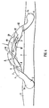
- FIG. 2 shows a prosthesis in the form of a vascular graft 10 comprising a length of hollow tubing forming an external sheath to a grafted vessel (not shown).
- the tubing has an inlet 2 at one end and an outlet 3 at the other end.
- a generally helical tubing portion 1 is provided at the outlet 3 thereof.
- the prosthesis has inlet 2a and outlet 3a flaps at its ends which have been surgically fastened by suturing to regions of an artery remote from a blockage 7 in the artery, the prosthesis thus acting as an arterial bypass graft. It could also be surgically connected between an artery and a vein so as a vascular access graft for e.g. renal dialysis.
- Blood from the circulatory system can flow from the inlet 2 to the outlet 3 along a hollow interior or lumen 4 of the vessel.
- the helically formed tubing portion 1 is disposed adjacent to the outlet 3. Its non-planar curvature induces a swirl to the flow to improve circulation by rendering the distribution of wall shear stresses relatively uniform and suppressing flow separation and flow instability, and as a result inhibiting the development of vessel pathology.
- the swirl flow may also resist the build up of intimal hyperplasia at the join and downstream of the join with the vein or artery.
- the tubing can be made of suitable bio-compatible material and such materials are commercially available and known to those skilled in the art. In order to maintain the tubing open and prevent collapse or kinking it is possible to use a stent or other structural support of plastic, metal or other material internally, externally or integral to the wall of the tubing.
- the prosthesis 10 in Figure 2 is generally arch shaped. This arch may itself be provided in a single plane. If the arch is non-planar then this will also tend to induce swirl flow and it will be desirable to ensure that the swirl flow induced by the non-planar arch is in the same direction as that induced by the helical tubing portion 1.
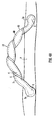
- FIG. 3 The arrangement of Figure 3 is similar to that of Figure 2 , except that the helically formed tubing portion 1 extends substantially the full length of the prosthesis 10. This type of arrangement may simplify manufacture as the tubing could be made in a continuous length which simply has to be cut to appropriate shorter lengths to form prostheses.
- the swept width W defines the width of the envelope.
- the longitudinal axis 30 of the envelope is curved, the tubular portion being arch shaped.
- the centre line 40 follows a helical path about the axis 30.
- the vascular graft 10 shown in Figure 4a comprises tubing 1 forming an external sheath to a grafted vessel 60 (see Figure 4b ) and having a substantially circular cross-section.
- the tubing is coiled into a helix of constant amplitude A (as measured from mean to extreme), constant pitch P, constant helix angle ⁇ and a swept width W.
- the tubing 1 is contained in an imaginary envelope 20 which extends longitudinally and has a width equal to the swept width W of the helix.
- the envelope 20 may be regarded as having a central longitudinal axis 30, which may also be referred to as an axis of helical rotation.
- the illustrated tubing 1 has a curved axis 30.
- the tubing has a centre line 40 which follows a helical path about the central longitudinal axis 30.
- the tubing 1 has a helical portion 6 extending longitudinally and circumferentially with the same pitch as pitch P of the helical centre line 40.
- the helical portion 6 consists of a strip of material secured to the wall 62 of the tubing 1.
- the tubing 1 has an inlet 2 at one end and an outlet 3 at the other end.
- the tubing has inlet 2a and outlet 3a flaps at its ends which have been surgically fastened by suturing to regions of an artery 8 remote from a blockage 7 in the artery, the graft 10 thus acting as an arterial bypass graft. It could also be surgically connected between an artery and a vein so as to serve as a vascular access graft for e.g. renal dialysis.
- Figure 4b shows the grafted vessel 60 contained in the tubing 1, the tubing acting as an external sheath.
- the vessel 60 is a loose fit in the tubing, even when pressurised, but nevertheless has a tendency to try and straighten out the helical geometry of the tubing 1. This is resisted by the helical portion 6, by virtue of its relatively lower extensibility as compared to the rest of the wall 62 of the tubing.
- Blood from the circulatory system can flow from the inlet 2 to the outlet 3 along a hollow interior or lumen 4 of the graft 10. It operates in a manner similar to the graft of Figure 3 , having a non-planar curvature which induces a swirl to the flow to improve circulation and resist the development of pathology.
- the swirl flow may also resist the build up of intimal hyperplasia at the join and downstream of the join with the vein or artery.
- External stents of helical form are implanted over a venous arterial or prosthetic graft or intact blood vessel to cause the geometrical configuration of the graft or vessel, e.g. artery, to adopt a predetermined form to promote swirl flow.
- the tubing 1 may be made of various materials, which are preferably flexible. Suitable bio-compatible materials are commercially available and known to those skilled in the art. External stents may for example be made of a thermosettable plastic, biodegradable material, or a supported synthetic woven material, in the form of a hollow tube, the walls of which contain numerous openings, or have a micro- or macro-porosity, so that the exterior of the graft or vein is not fully shielded.
- One suitable material known for use as an external sheath, is polyester.
- a knitted polyester yarn such as polyethylene terephthalate, known as Dacron (trade mark) is a particular example.
- the helical portion may be made of the same material or another material, such as polypropylene.
- the helical portion rather than being a separate strip secured to the wall 62 of the tubing 1, may be an integral part thereof, for example by being knitted or stitched in to the wall.
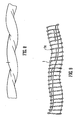
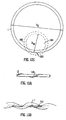
- Figure 5 shows the result of an experiment carried out on a toy balloon 55.
- the balloon was of the elongated type. It was supported, without being inflated, on a cylindrical rod and a plastic strip 51 cut from another balloon was glued onto the outside of the supported balloon to form a longitudinally and circumferentially extending helical strip 6. A straight line 50 was drawn along the balloon. After the glue had set, the balloon was inflated and the inflated balloon is shown in Figure 5 .
- the inflated balloon 55 has a helical lumen. As with the tubing for fluid flow, it has a helical centre line 40, which follows a helical path about a longitudinal axis 30. The longitudinal axis is at the centre of an imaginary cylindrical envelope 20 within which the balloon is contained. The amplitude A of the helix is shown in Figure 5 .
- the balloon of Figure 5 starts as a cylindrical membrane with a helical portion which is of greater (in this case double) wall thickness than the rest of the balloon. During inflation the thicker helical portion will tend to resist extension in all directions, including circumferential and longitudinal directions, thereby influencing the shape of the expanded balloon. Instead of adopting the normal cylindrical shape, the balloon forms a shape with a helical centre line 40.
- the balloon is internally pressurised in a manner to some extent analogous with the internal pressurisation of the tubing of the preferred embodiments of the invention.
- the helical portion causes what would otherwise be a cylindrical shape to adopt and maintain helical geometry.
- a similar effect is obtained by the helical portion of the tubing for body fluid flow, wherein the helical portion tends to help the tubing maintain its helical longitudinal cavity, i.e. to resist "straightening out".
- a tubing having a wall defining a longitudinally extending cavity having a centre line following a substantially helical path was manufactured as follows.
- a pair of flexible cylindrical tubes made from polyester were internally supported by insertion of respective closely fitting coiled springs.
- the two supported tubes were then positioned adjacent to each other and twisted around each other.
- the pair of tubes were thermoset in the twisted configuration by immersion in hot water followed by removal and cooling.
- the tubes were separated and the coil springs removed.
- the internal geometry of each tube so formed consisted of a longitudinally extending cavity having a centre line following a substantially helical path.
- One of the tubes was subjected to internal pressurisation by insertion of a cylindrical balloon which was then gently inflated. Because of the flexible nature of the material forming the tube, the effect of the internal pressurisation was to straighten out the helix, in that the pitch was increased and the amplitude decreased.
- tubing having a wall defining a longitudinally extending cavity with a centre line following a substantially helical path.
- the tubing was made of expanded polytetrafluoroethylene (ePTFE).
- ePTFE expanded polytetrafluoroethylene
- Biocompatible tubing of this type is available for use as vascular prostheses, for example from Vascutek Limited or Boston Scientific Corporation.
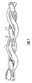
- a length of ePTFE tubing 1 was internally supported by insertion of a length of silicone rubber tubing 70.
- a length of polyvinyl chloride (PVC) tubing 71 was internally supported by insertion of a closely fitting coiled spring.
- the two supported tubes were positioned adjacent to each other and twisted around each other.
- the support tube 70 was clamped at each end by respective clamps 73, these clamps also serving to clamp the ends of the PVC tube 71.
- the internally supported, twisted and clamped tubes were placed in an oven at 180°C for 5 minutes and then cooled by immersion in water at room temperature. The tubes were separated and the support tube 70 was removed from the tubing 1.
- the tubing was thermoset in a twisted configuration, as seen in Figure 8 . Although the amplitude of the helix was reduced compared to the amplitude during the heating step, the tubing had the desired longitudinally extended cavity with a centre line following a substantially helical path.
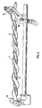
- Figure 9 shows another length of ePTFE tubing manufactured using the above method.
- the tubing 1 used at the start was of the armoured type, having an external helical winding 74 with a large helix angle (close to 90°).
- This type of tubing is used in prostheses subject to external bending forces, for example going across joints such as the knee, and the helical winding serves to help maintain a circular cross-section.
- armoured tubing was also successfully modified to have a longitudinally extending cavity with a centre line following a substantially helical path.
- An elongate member in the form of a thread 101, is helically wound round an initially cylindrical tube 1.
- the thread 101 is arranged helically along the tubing so as to extend longitudinally and circumferentially thereof.
- the thread is tensioned and causes the tube to distort helically, such that its longitudinally extending cavity has a centre line following a substantially helical path.
- the pitch is dictated by the pitch of the winding of the thread.
- the amplitude is dictated by the tension on the thread.
- the tension, and hence the helical deformation is maintained by securing the ends of the thread, for example to a suitable rig.
- the deformed tube is then heated so as to thermoset and so as to soften the thread sufficiently for it to bond to the tube.
- the thread therefore serves the purposes first of creating the helical geometry during the tensioning step, and later of helping to retain that geometry when the tube is used and internally pressurised by e.g. arterial pressure.
- the tubing may be externally or internally supported during this process.
- a knitted polyester yarn such as polyethylene terephthalate, known as Dacron (trade mark), is a suitable material for the tube, whilst the elongate member may be polypropylene.
- the tube may be externally supported with helically wound (with a very large helix angle, close to 90°) polypropylene. With these materials the heating step is carried out by heating the tube and tensioned thread in an oven at 140°C.
- the tube is initially cylindrical, with a helical portion extending along its wall.
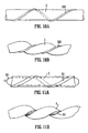
- the method is described with reference to Figures 11a and 11b .
- tubing 1 is provided with a reinforcing strip 51 adhered to its outside surface so as to extend longitudinally and circumferentially of the tubing.
- An inflatable device 55 is located inside the tubing.
- the inflatable device is inflated in order to expand the tubing.
- the helically arranged strip 51 causes the tubing to expand to a shape having a longitudinal, helical cavity, as seen in Figure 11b .
- the tubing adopts the helical geometry in the same manner as the balloon shown in Figure 5 .
- the tubing is thermoset in this condition and allowed to cool, in order to retain the desired helical shape.
- the material of the inflatable device 55 is chosen to withstand the elevated temperature required to thermoset the tubing.
- the helical portion in the form of strip 51, thus serves the purposes first of creating the helical geometry during the inflation step, and later of helping to retain that geometry when the tube is used and internally pressurised by e.g. arterial pressure.
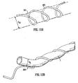
- Figure 12a is a schematic illustration of a helical mandrel for use in this method.
- the mandrel consists of a rigid rod 300; shaped into a helix.
- the mandrel extends longitudinally and circumferentially around a cylindrical space which defines a core 301 of the mandrel.
- the pitch and the amplitude of the helix are constant along the length of the mandrel, but they may vary if desired.
- a length of straight flexible tube 1 whose external diameter D R is greater than the internal diameter D M of the core of the mandrel, is fed generally along the core of the mandrel, as shown in Figure 12b , Because the tube is wider than the space inside the mandrel, it is forced to adopt a helical form.
- the tube may be externally or internally supported to retain its cross-sectional shape during this process.
- the tube After being treated to make it retain its helical shape, e.g. by thermosetting, the tube is removed from the mandrel, as shown in Figures 12c and 12d .
- the pitch of the helical portion is the same as the pitch of the mandrel, subject to some possible relaxation of the tube when removed from the mandrel.
- the amplitude of the helical portion will be determined by the external diameter of the tube and the internal diameter of the core of the mandrel.
- a continuous length of flexible tube can be drawn through a comparatively short length of mandrel, and can be treated to retain its shape as it is drawn through (for example, by heating and then cooling a tube formed from a thermosetting resin).
- Figure 12e is a schematic cross-section through the tube and the mandrel as the tube is drawn. It will be seen that the mandrel contacts the outside of the tube, and so the mandrel can be supported from below (at 320) without interfering with the drawing process.
- the mandrel can be formed in any suitable manner, and the method of forming the mandrel will depend to a large extent on the size of the tubes being treated.
- the mandrel could be formed by winding a rod around a member with a circular cross-section, or it may be made by machining, for example using a CNC milling machine.
- Figure 13a shows a straight steel rod 110 held in tension between two clamps (not shown).
- a soft steel wire 112 has been wound on to the steel rod in a helical manner, i.e. to extend longitudinally and circumferentially of the rod.
- the wire 112 is secured in place by silver solder.
- the wire 112 forms a guide showing where a tubing 1 is to be wound around the rod 110, which acts as a mandrel.
- the pitch (or helix angle) of the tubing when wound onto the rod is predetermined.
- the tubing is then heated and cooled in order to thermoset it. It is separated from the rod and when it separates it "relaxes" whereby its helical amplitude reduces.
- the tubing is made of ePTFE.
- a R A D I
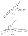
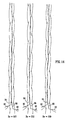
- Figure 14 shows the results of three experiments, at Reynolds numbers R E of 500, 250 and 100 respectively. It will be seen in all cases that the ink filaments 84 and 86 intertwine, indicating that in the core there is swirl flow, i.e. flow which is generally rotating.
- Example 15 shows the results of two experiments with near-wall ink release, with Reynolds numbers R E of 500 and 250 respectively. It will be seen that in both cases the ink filaments follow the helical tubing geometry, indicating near-wall swirl. Furthermore, mixing of the ink filaments with the water is promoted.
- this invention in its first aspect, is concerned with values of relative amplitude A R less than or equal to 0.5, i.e. small relative amplitudes.
- both the amplitude A and the relative amplitude A R equal zero, as there is no helix. Therefore, with values of relative amplitude A R approaching zero, the ability of the tubing portion to induce swirl will reduce.
- the lowest workable value of relative amplitude A R for any given situation will depend on the speed of flow and the viscosity and density of the fluid (i.e. Reynolds number) and on the pitch (helix angle) and the particular use of the tubing portion.
- Relative amplitudes of at least 0.05, 0.10, 0.15, 0.20, 0.25, 0.30, 0.35, 0.40 or 0.45 may be preferred.
- the various manufacturing methods described herein are not limited to the manufacture of tubing with a relative amplitude equal to or less than 0.5, unless otherwise specified.
- the methods are applicable to the manufacture of tubing with larger amplitudes, whilst also being particularly useful for making tubing of small relative amplitudes.
Claims (7)
- Vorrichtung zur externen Platzierung extern zu einer Körperflüssigkeiten-Flussleitung, mit einem Rohrabschnitt (1) mit einer Wand, die einen sich längs erstreckenden Hohlraum zur Aufnahme der Leitung definiert, wobei der sich längs erstreckende Hohlraum des Rohrabschnitts im Wesentlichen frei von Rippen oder Rinnen bzw. Nuten ist, wobei die Mittenlinie bzw. Achse (40) des sich längs erstreckenden Hohlraums einem im Wesentlichen schneckenförmigen bzw. helikalen Pfad mit einem Schneckenwinkel (θ) geringer oder gleich 65° folgt, wobei die Amplitude (A) der Helix kleiner oder gleich der Hälfte des Innendurchmessers (DI) des Rohrabschnitts (1) ist, und dadurch gekennzeichnet, dass die Wand einen helikalen Abschnitt (6) aufweist, der sich längs und umgebend bzw. umfänglich erstreckt, und der, verglichen mit benachbarten Abschnitten der Rohrabschnittswand, eine geringere Ausdehnbarkeit aufweist.
- Vorrichtung nach Anspruch 1, bei der die Steigung des schneckenförmigen Abschnitts (6) gleich der Steigung der schneckenförmigen Mittenlinie (40) des Längshohlraums ist.
- Vorrichtung nach Anspruch 1 oder 2, bei der der schneckenförmige Abschnitt (6) in der Radialrichtung dicker ist als benachbarte Abschnitte der Rohrabschnittswand.
- Vorrichtung nach Anspruch 1, 2 oder 3, bei der der schneckenförmige Abschnitt (6) aus einem Material hergestellt ist, das unterschiedlich zu jedem der benachbarten Abschnitte der Rohrabschnittswand ist.
- Vorrichtung nach einem der vorstehenden Ansprüche, bei der die Amplitude (A) der schneckenförmigen Mittenlinie (40), geteilt durch den inneren Durchmesser (DI) des Rohrs, wenigstens 0,05 beträgt.
- Vorrichtung nach einem der vorstehenden Ansprüche, bei der der Schneckenwinkel (θ) kleiner oder gleich 15° ist.
- Vorrichtung nach einem der vorstehenden Ansprüche, die eine pharmazeutische Beschichtung aufweist.
Applications Claiming Priority (9)
| Application Number | Priority Date | Filing Date | Title |
|---|---|---|---|
| GBGB0306176.9A GB0306176D0 (en) | 2003-03-18 | 2003-03-18 | Tubing |
| GB0306176 | 2003-03-18 | ||
| GB0317004 | 2003-07-21 | ||
| GB0317004A GB0317004D0 (en) | 2003-07-21 | 2003-07-21 | Tubing |
| GB0321327 | 2003-09-11 | ||
| GB0321327A GB0321327D0 (en) | 2003-09-11 | 2003-09-11 | Tubing |
| GB0328757A GB0328757D0 (en) | 2003-12-11 | 2003-12-11 | Tubing |
| GB0328757 | 2003-12-11 | ||
| PCT/GB2004/001169 WO2004082520A2 (en) | 2003-03-18 | 2004-03-18 | Device for placement externally of a body fluid flow conduit |
Publications (2)
| Publication Number | Publication Date |
|---|---|
| EP1603490A2 EP1603490A2 (de) | 2005-12-14 |
| EP1603490B1 true EP1603490B1 (de) | 2010-05-26 |
Family
ID=33033226
Family Applications (2)
| Application Number | Title | Priority Date | Filing Date |
|---|---|---|---|
| EP04721566A Expired - Lifetime EP1603490B1 (de) | 2003-03-18 | 2004-03-18 | Platzierungsvorrichtung für eine prothese auf einer körperröhre |
| EP04721575A Expired - Lifetime EP1605868B1 (de) | 2003-03-18 | 2004-03-18 | Spiralförmiges implantat |
Family Applications After (1)
| Application Number | Title | Priority Date | Filing Date |
|---|---|---|---|
| EP04721575A Expired - Lifetime EP1605868B1 (de) | 2003-03-18 | 2004-03-18 | Spiralförmiges implantat |
Country Status (9)
| Country | Link |
|---|---|
| US (1) | US20070156078A1 (de) |
| EP (2) | EP1603490B1 (de) |
| JP (2) | JP4503011B2 (de) |
| AT (2) | ATE468829T1 (de) |
| AU (2) | AU2004222495A1 (de) |
| BR (2) | BRPI0408431A (de) |
| CA (2) | CA2519381A1 (de) |
| DE (2) | DE602004018283D1 (de) |
| WO (2) | WO2004082534A1 (de) |
Families Citing this family (14)
| Publication number | Priority date | Publication date | Assignee | Title |
|---|---|---|---|---|
| GB0306176D0 (en) * | 2003-03-18 | 2003-04-23 | Imp College Innovations Ltd | Tubing |
| GB0306179D0 (en) * | 2003-03-18 | 2003-04-23 | Imp College Innovations Ltd | Piping |
| US7749462B2 (en) | 2004-09-21 | 2010-07-06 | Technip France S.A.S. | Piping |
| US8029749B2 (en) | 2004-09-21 | 2011-10-04 | Technip France S.A.S. | Cracking furnace |
| GB0420971D0 (en) * | 2004-09-21 | 2004-10-20 | Imp College Innovations Ltd | Piping |
| GB2427668A (en) * | 2005-06-24 | 2007-01-03 | Veryan Medical Ltd | Method of forming artificial graft tubing |
| GB0707190D0 (en) * | 2007-04-13 | 2007-05-23 | Veryan Medical Ltd | Graft |
| GB0817219D0 (en) | 2008-09-19 | 2008-10-29 | Heliswirl Petrochemicals Ltd | Cracking furnace |
| US9597214B2 (en) * | 2008-10-10 | 2017-03-21 | Kevin Heraty | Medical device |
| US9149377B2 (en) * | 2008-10-10 | 2015-10-06 | Veryan Medical Ltd. | Stent suitable for deployment in a blood vessel |
| GB2475338A (en) * | 2009-11-17 | 2011-05-18 | Tayside Flow Technologies Ltd | A tubular conduit with an internal and external helical formation |
| BR112015021831A2 (pt) | 2013-03-15 | 2017-07-18 | Veryan Medical Ltd | aparelho de stent e métodos de tratamento |
| DK2991565T3 (da) | 2013-05-02 | 2019-09-02 | Veryan Medical Ltd | Ekspanderbar ballon |
| CN110037837B (zh) * | 2019-04-03 | 2021-10-01 | 中山大学附属第三医院 | 一种可变管径的自适应胰管支架管 |
Family Cites Families (20)
| Publication number | Priority date | Publication date | Assignee | Title |
|---|---|---|---|---|
| FR2248015A1 (en) * | 1973-10-17 | 1975-05-16 | Rhone Poulenc Ind | Artificial ureter or urethra - watertight flexible tube has helical rib in outside wall to prevent creasing |
| US4604762A (en) * | 1981-02-13 | 1986-08-12 | Thoratec Laboratories Corporation | Arterial graft prosthesis |
| US4596548A (en) * | 1985-03-25 | 1986-06-24 | Dlp Inc. | Single stage venous catheter |
| US5156619A (en) * | 1990-06-15 | 1992-10-20 | Ehrenfeld William K | Flanged end-to-side vascular graft |
| US5282847A (en) * | 1991-02-28 | 1994-02-01 | Medtronic, Inc. | Prosthetic vascular grafts with a pleated structure |
| US5441515A (en) * | 1993-04-23 | 1995-08-15 | Advanced Cardiovascular Systems, Inc. | Ratcheting stent |
| US6039754A (en) | 1993-10-01 | 2000-03-21 | Imperial College Of Science Technology & Medicine | Vascular prostheses |
| US5865723A (en) * | 1995-12-29 | 1999-02-02 | Ramus Medical Technologies | Method and apparatus for forming vascular prostheses |
| US6152139A (en) * | 1997-01-24 | 2000-11-28 | Heartenmedical, Inc. | Device and method for preparing veins |
| GB9710905D0 (en) | 1997-05-27 | 1997-07-23 | Imperial College | Stent for blood vessel |
| ATE322230T1 (de) * | 1998-09-10 | 2006-04-15 | Percardia Inc | Tmr vorrichtung |
| GB2344053A (en) | 1998-11-30 | 2000-05-31 | Imperial College | Stents for blood vessels |
| GB9828696D0 (en) * | 1998-12-29 | 1999-02-17 | Houston J G | Blood-flow tubing |
| US6440166B1 (en) * | 1999-02-16 | 2002-08-27 | Omprakash S. Kolluri | Multilayer and multifunction vascular graft |
| US7214229B2 (en) * | 1999-03-18 | 2007-05-08 | Fossa Medical, Inc. | Radially expanding stents |
| EP1127557A1 (de) | 2000-02-25 | 2001-08-29 | EndoArt S.A. | Gefässtransplantat |
| DE10012460A1 (de) * | 2000-03-15 | 2001-09-20 | Biotronik Mess & Therapieg | Stent |
| EP1179322A3 (de) * | 2000-08-09 | 2004-02-25 | BIOTRONIK Mess- und Therapiegeräte GmbH & Co Ingenieurbüro Berlin | Verfahren und Vorrichtung zum Crimpen eines Stents |
| DE10044043A1 (de) * | 2000-08-30 | 2002-03-14 | Biotronik Mess & Therapieg | Reponierbarer Stent |
| GB2379996B (en) * | 2001-06-05 | 2004-05-19 | Tayside Flow Technologies Ltd | Flow means |
-
2004
- 2004-03-18 EP EP04721566A patent/EP1603490B1/de not_active Expired - Lifetime
- 2004-03-18 WO PCT/GB2004/001156 patent/WO2004082534A1/en active Application Filing
- 2004-03-18 BR BRPI0408431-4A patent/BRPI0408431A/pt not_active IP Right Cessation
- 2004-03-18 EP EP04721575A patent/EP1605868B1/de not_active Expired - Lifetime
- 2004-03-18 AU AU2004222495A patent/AU2004222495A1/en not_active Abandoned
- 2004-03-18 AU AU2004222496A patent/AU2004222496A1/en not_active Abandoned
- 2004-03-18 AT AT04721566T patent/ATE468829T1/de not_active IP Right Cessation
- 2004-03-18 JP JP2006505979A patent/JP4503011B2/ja not_active Expired - Lifetime
- 2004-03-18 DE DE602004018283T patent/DE602004018283D1/de not_active Expired - Lifetime
- 2004-03-18 CA CA002519381A patent/CA2519381A1/en not_active Abandoned
- 2004-03-18 JP JP2006505984A patent/JP4352074B2/ja not_active Expired - Fee Related
- 2004-03-18 DE DE602004027353T patent/DE602004027353D1/de not_active Expired - Lifetime
- 2004-03-18 WO PCT/GB2004/001169 patent/WO2004082520A2/en active Application Filing
- 2004-03-18 BR BRPI0408412-8A patent/BRPI0408412A/pt not_active IP Right Cessation
- 2004-03-18 US US10/549,211 patent/US20070156078A1/en not_active Abandoned
- 2004-03-18 CA CA002519406A patent/CA2519406A1/en not_active Abandoned
- 2004-03-18 AT AT04721575T patent/ATE416722T1/de not_active IP Right Cessation
Also Published As
| Publication number | Publication date |
|---|---|
| AU2004222496A1 (en) | 2004-09-30 |
| ATE416722T1 (de) | 2008-12-15 |
| WO2004082534A1 (en) | 2004-09-30 |
| JP2006520631A (ja) | 2006-09-14 |
| WO2004082520A2 (en) | 2004-09-30 |
| JP4352074B2 (ja) | 2009-10-28 |
| BRPI0408431A (pt) | 2006-03-21 |
| BRPI0408412A (pt) | 2006-03-21 |
| US20070156078A1 (en) | 2007-07-05 |
| DE602004027353D1 (de) | 2010-07-08 |
| CA2519406A1 (en) | 2004-09-30 |
| ATE468829T1 (de) | 2010-06-15 |
| WO2004082520A3 (en) | 2004-11-11 |
| EP1605868A1 (de) | 2005-12-21 |
| AU2004222495A1 (en) | 2004-09-30 |
| EP1603490A2 (de) | 2005-12-14 |
| JP2006520632A (ja) | 2006-09-14 |
| CA2519381A1 (en) | 2004-09-30 |
| EP1605868B1 (de) | 2008-12-10 |
| JP4503011B2 (ja) | 2010-07-14 |
| DE602004018283D1 (de) | 2009-01-22 |
Similar Documents
| Publication | Publication Date | Title |
|---|---|---|
| US9572694B2 (en) | Helical graft | |
| EP2292183B1 (de) | Spiralförmiger Ballon mit Stent | |
| US7462190B2 (en) | Stent matrix | |
| EP1603490B1 (de) | Platzierungsvorrichtung für eine prothese auf einer körperröhre | |
| US9649186B2 (en) | Tubular conduit | |
| JP2006520632A5 (de) | ||
| US9486346B2 (en) | Balloon expandable stent graft and apparatus and method for expanding a balloon expandable stent graft | |
| US20090293574A1 (en) | Artifical Graft Tubing | |
| US20070150042A1 (en) | Stents with beveled ends and methods of use thereof | |
| GB2427668A (en) | Method of forming artificial graft tubing |
Legal Events
| Date | Code | Title | Description |
|---|---|---|---|
| PUAI | Public reference made under article 153(3) epc to a published international application that has entered the european phase |
Free format text: ORIGINAL CODE: 0009012 |
|
| 17P | Request for examination filed |
Effective date: 20051004 |
|
| AK | Designated contracting states |
Kind code of ref document: A2 Designated state(s): AT BE BG CH CY CZ DE DK EE ES FI FR GB GR HU IE IT LI LU MC NL PL PT RO SE SI SK TR |
|
| AX | Request for extension of the european patent |
Extension state: AL LT LV MK |
|
| DAX | Request for extension of the european patent (deleted) | ||
| 17Q | First examination report despatched |
Effective date: 20080806 |
|
| GRAP | Despatch of communication of intention to grant a patent |
Free format text: ORIGINAL CODE: EPIDOSNIGR1 |
|
| GRAS | Grant fee paid |
Free format text: ORIGINAL CODE: EPIDOSNIGR3 |
|
| GRAA | (expected) grant |
Free format text: ORIGINAL CODE: 0009210 |
|
| RAP1 | Party data changed (applicant data changed or rights of an application transferred) |
Owner name: VERYAN MEDICAL LIMITED |
|
| AK | Designated contracting states |
Kind code of ref document: B1 Designated state(s): AT BE BG CH CY CZ DE DK EE ES FI FR GB GR HU IE IT LI LU MC NL PL PT RO SE SI SK TR |
|
| REG | Reference to a national code |
Ref country code: GB Ref legal event code: FG4D |
|
| REG | Reference to a national code |
Ref country code: CH Ref legal event code: NV Representative=s name: BOHEST AG Ref country code: CH Ref legal event code: EP |
|
| REG | Reference to a national code |
Ref country code: IE Ref legal event code: FG4D |
|
| REF | Corresponds to: |
Ref document number: 602004027353 Country of ref document: DE Date of ref document: 20100708 Kind code of ref document: P |
|
| REG | Reference to a national code |
Ref country code: NL Ref legal event code: T3 |
|
| PG25 | Lapsed in a contracting state [announced via postgrant information from national office to epo] |
Ref country code: SE Free format text: LAPSE BECAUSE OF FAILURE TO SUBMIT A TRANSLATION OF THE DESCRIPTION OR TO PAY THE FEE WITHIN THE PRESCRIBED TIME-LIMIT Effective date: 20100526 |
|
| PG25 | Lapsed in a contracting state [announced via postgrant information from national office to epo] |
Ref country code: AT Free format text: LAPSE BECAUSE OF FAILURE TO SUBMIT A TRANSLATION OF THE DESCRIPTION OR TO PAY THE FEE WITHIN THE PRESCRIBED TIME-LIMIT Effective date: 20100526 Ref country code: FI Free format text: LAPSE BECAUSE OF FAILURE TO SUBMIT A TRANSLATION OF THE DESCRIPTION OR TO PAY THE FEE WITHIN THE PRESCRIBED TIME-LIMIT Effective date: 20100526 Ref country code: SI Free format text: LAPSE BECAUSE OF FAILURE TO SUBMIT A TRANSLATION OF THE DESCRIPTION OR TO PAY THE FEE WITHIN THE PRESCRIBED TIME-LIMIT Effective date: 20100526 |
|
| PG25 | Lapsed in a contracting state [announced via postgrant information from national office to epo] |
Ref country code: PL Free format text: LAPSE BECAUSE OF FAILURE TO SUBMIT A TRANSLATION OF THE DESCRIPTION OR TO PAY THE FEE WITHIN THE PRESCRIBED TIME-LIMIT Effective date: 20100526 Ref country code: GR Free format text: LAPSE BECAUSE OF FAILURE TO SUBMIT A TRANSLATION OF THE DESCRIPTION OR TO PAY THE FEE WITHIN THE PRESCRIBED TIME-LIMIT Effective date: 20100827 Ref country code: CY Free format text: LAPSE BECAUSE OF FAILURE TO SUBMIT A TRANSLATION OF THE DESCRIPTION OR TO PAY THE FEE WITHIN THE PRESCRIBED TIME-LIMIT Effective date: 20100526 |
|
| PG25 | Lapsed in a contracting state [announced via postgrant information from national office to epo] |
Ref country code: PT Free format text: LAPSE BECAUSE OF FAILURE TO SUBMIT A TRANSLATION OF THE DESCRIPTION OR TO PAY THE FEE WITHIN THE PRESCRIBED TIME-LIMIT Effective date: 20100927 Ref country code: EE Free format text: LAPSE BECAUSE OF FAILURE TO SUBMIT A TRANSLATION OF THE DESCRIPTION OR TO PAY THE FEE WITHIN THE PRESCRIBED TIME-LIMIT Effective date: 20100526 Ref country code: DK Free format text: LAPSE BECAUSE OF FAILURE TO SUBMIT A TRANSLATION OF THE DESCRIPTION OR TO PAY THE FEE WITHIN THE PRESCRIBED TIME-LIMIT Effective date: 20100526 |
|
| PG25 | Lapsed in a contracting state [announced via postgrant information from national office to epo] |
Ref country code: SK Free format text: LAPSE BECAUSE OF FAILURE TO SUBMIT A TRANSLATION OF THE DESCRIPTION OR TO PAY THE FEE WITHIN THE PRESCRIBED TIME-LIMIT Effective date: 20100526 Ref country code: RO Free format text: LAPSE BECAUSE OF FAILURE TO SUBMIT A TRANSLATION OF THE DESCRIPTION OR TO PAY THE FEE WITHIN THE PRESCRIBED TIME-LIMIT Effective date: 20100526 Ref country code: CZ Free format text: LAPSE BECAUSE OF FAILURE TO SUBMIT A TRANSLATION OF THE DESCRIPTION OR TO PAY THE FEE WITHIN THE PRESCRIBED TIME-LIMIT Effective date: 20100526 Ref country code: BE Free format text: LAPSE BECAUSE OF FAILURE TO SUBMIT A TRANSLATION OF THE DESCRIPTION OR TO PAY THE FEE WITHIN THE PRESCRIBED TIME-LIMIT Effective date: 20100526 |
|
| PLBE | No opposition filed within time limit |
Free format text: ORIGINAL CODE: 0009261 |
|
| STAA | Information on the status of an ep patent application or granted ep patent |
Free format text: STATUS: NO OPPOSITION FILED WITHIN TIME LIMIT |
|
| 26N | No opposition filed |
Effective date: 20110301 |
|
| REG | Reference to a national code |
Ref country code: DE Ref legal event code: R097 Ref document number: 602004027353 Country of ref document: DE Effective date: 20110228 |
|
| REG | Reference to a national code |
Ref country code: NL Ref legal event code: V1 Effective date: 20111001 |
|
| PG25 | Lapsed in a contracting state [announced via postgrant information from national office to epo] |
Ref country code: MC Free format text: LAPSE BECAUSE OF NON-PAYMENT OF DUE FEES Effective date: 20110331 |
|
| REG | Reference to a national code |
Ref country code: CH Ref legal event code: PL |
|
| GBPC | Gb: european patent ceased through non-payment of renewal fee |
Effective date: 20110318 |
|
| REG | Reference to a national code |
Ref country code: FR Ref legal event code: ST Effective date: 20111130 |
|
| REG | Reference to a national code |
Ref country code: IE Ref legal event code: MM4A |
|
| PG25 | Lapsed in a contracting state [announced via postgrant information from national office to epo] |
Ref country code: FR Free format text: LAPSE BECAUSE OF NON-PAYMENT OF DUE FEES Effective date: 20110331 Ref country code: IE Free format text: LAPSE BECAUSE OF NON-PAYMENT OF DUE FEES Effective date: 20110318 Ref country code: NL Free format text: LAPSE BECAUSE OF NON-PAYMENT OF DUE FEES Effective date: 20111001 Ref country code: CH Free format text: LAPSE BECAUSE OF NON-PAYMENT OF DUE FEES Effective date: 20110331 Ref country code: DE Free format text: LAPSE BECAUSE OF NON-PAYMENT OF DUE FEES Effective date: 20111001 Ref country code: LI Free format text: LAPSE BECAUSE OF NON-PAYMENT OF DUE FEES Effective date: 20110331 |
|
| REG | Reference to a national code |
Ref country code: DE Ref legal event code: R119 Ref document number: 602004027353 Country of ref document: DE Effective date: 20111001 |
|
| PG25 | Lapsed in a contracting state [announced via postgrant information from national office to epo] |
Ref country code: IT Free format text: LAPSE BECAUSE OF NON-PAYMENT OF DUE FEES Effective date: 20110318 Ref country code: GB Free format text: LAPSE BECAUSE OF NON-PAYMENT OF DUE FEES Effective date: 20110318 |
|
| PG25 | Lapsed in a contracting state [announced via postgrant information from national office to epo] |
Ref country code: LU Free format text: LAPSE BECAUSE OF NON-PAYMENT OF DUE FEES Effective date: 20110318 |
|
| PG25 | Lapsed in a contracting state [announced via postgrant information from national office to epo] |
Ref country code: BG Free format text: LAPSE BECAUSE OF FAILURE TO SUBMIT A TRANSLATION OF THE DESCRIPTION OR TO PAY THE FEE WITHIN THE PRESCRIBED TIME-LIMIT Effective date: 20100826 Ref country code: TR Free format text: LAPSE BECAUSE OF FAILURE TO SUBMIT A TRANSLATION OF THE DESCRIPTION OR TO PAY THE FEE WITHIN THE PRESCRIBED TIME-LIMIT Effective date: 20100526 |
|
| PG25 | Lapsed in a contracting state [announced via postgrant information from national office to epo] |
Ref country code: HU Free format text: LAPSE BECAUSE OF FAILURE TO SUBMIT A TRANSLATION OF THE DESCRIPTION OR TO PAY THE FEE WITHIN THE PRESCRIBED TIME-LIMIT Effective date: 20100526 Ref country code: ES Free format text: LAPSE BECAUSE OF FAILURE TO SUBMIT A TRANSLATION OF THE DESCRIPTION OR TO PAY THE FEE WITHIN THE PRESCRIBED TIME-LIMIT Effective date: 20100906 |