EP1603199B1 - Electrical connecting device - Google Patents
Electrical connecting device Download PDFInfo
- Publication number
- EP1603199B1 EP1603199B1 EP05360004A EP05360004A EP1603199B1 EP 1603199 B1 EP1603199 B1 EP 1603199B1 EP 05360004 A EP05360004 A EP 05360004A EP 05360004 A EP05360004 A EP 05360004A EP 1603199 B1 EP1603199 B1 EP 1603199B1
- Authority
- EP
- European Patent Office
- Prior art keywords
- connection
- grids
- connection device
- track
- terminals
- Prior art date
- Legal status (The legal status is an assumption and is not a legal conclusion. Google has not performed a legal analysis and makes no representation as to the accuracy of the status listed.)
- Not-in-force
Links
Images
Classifications
-
- H—ELECTRICITY
- H01—ELECTRIC ELEMENTS
- H01R—ELECTRICALLY-CONDUCTIVE CONNECTIONS; STRUCTURAL ASSOCIATIONS OF A PLURALITY OF MUTUALLY-INSULATED ELECTRICAL CONNECTING ELEMENTS; COUPLING DEVICES; CURRENT COLLECTORS
- H01R12/00—Structural associations of a plurality of mutually-insulated electrical connecting elements, specially adapted for printed circuits, e.g. printed circuit boards [PCB], flat or ribbon cables, or like generally planar structures, e.g. terminal strips, terminal blocks; Coupling devices specially adapted for printed circuits, flat or ribbon cables, or like generally planar structures; Terminals specially adapted for contact with, or insertion into, printed circuits, flat or ribbon cables, or like generally planar structures
- H01R12/50—Fixed connections
- H01R12/59—Fixed connections for flexible printed circuits, flat or ribbon cables or like structures
- H01R12/61—Fixed connections for flexible printed circuits, flat or ribbon cables or like structures connecting to flexible printed circuits, flat or ribbon cables or like structures
- H01R12/613—Fixed connections for flexible printed circuits, flat or ribbon cables or like structures connecting to flexible printed circuits, flat or ribbon cables or like structures by means of interconnecting elements
-
- H—ELECTRICITY
- H01—ELECTRIC ELEMENTS
- H01R—ELECTRICALLY-CONDUCTIVE CONNECTIONS; STRUCTURAL ASSOCIATIONS OF A PLURALITY OF MUTUALLY-INSULATED ELECTRICAL CONNECTING ELEMENTS; COUPLING DEVICES; CURRENT COLLECTORS
- H01R2201/00—Connectors or connections adapted for particular applications
- H01R2201/26—Connectors or connections adapted for particular applications for vehicles
Definitions
- the present invention relates to the technical field of electrical connection and connection devices.
- This kind of connection and connection devices are used in particular in rotary contactors found for example in steering columns of a vehicle.
- These rotating contacts often include a set of flexible flat cables each having overmolded conductive tracks.
- Standard flat cables having six conductive tracks (6 channels) are thus known. It is often necessary for an ignition switch to have an input on the twelve-way link device, in this case two inputs with six channels each and a twelve-channel output which should be distributed according to different functionalities.
- the object of the present invention is to provide an electrical connection does not have the aforementioned drawbacks by increasing the number of possible uses and electrical connections while respecting where appropriate the safety standards.
- Another object of the present invention is also to facilitate assembly / disassembly operations especially in hard to reach places, such as steering wheel control or rotating vehicle steering column contacts.
- the document US6,575,772 describes a connector applying to the end of two flat cables.
- This connector comprises a printed circuit board having conductive tracks and a plurality of contact pins connected sliding against springs to said card.
- Each track of each flat cable is connected to a contact plug available at the output of the connector, the two cables being treated separately on both sides of the card. It is not possible to assign output channels from one side of the board to a flat cable track opening at the other side.
- connection grids once assembled, can optionally be used with an identical or different number of output terminals.
- connection grids are mounted, for example by clipping, on an electrical insulating support piece.
- the conductive tracks are at least partially integrated in a support of electrical insulating material, which has orifices into which said conductive tracks open to produce the input and output terminals.
- the conductive tracks are at least partially covered by an electrical insulating layer.
- the branch extending between the input or output terminal and respectively the end of the corresponding track of one of the grids has an elasticity improving contact with the end of the track of the other wire rack.
- the ends of the tracks are joined to each other by a weld point, after assembly of the connection grids.
- the first lead frame has six input terminals and four output terminals, the second gate having six input terminals and eight output terminals, said output terminals being adapted in particular for the commitment of Electric wires.
- the present invention also relates to an electrical connection device comprising two flat cables with six conductive tracks each and connected at one of their ends to a connection device according to that described above.
- the present invention also relates to a steering wheel control of a steering column of a vehicle comprising an electrical connection device as described above.
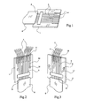
- the electrical connection device of the figure 1 is a standard device known as such.
- the Figures 2 and 3 represent an embodiment of a connection device and more particularly the constituent elements of said device in each of the figures.
- the electrical connection device comprises a first 1 and a second 2 connection grids each provided with a given number of input terminals 3 and output terminals 4. Each input terminal 3 is electrically connected to at least one terminal output 4 via a conductive track 5.
- connection device also comprises connecting means (not shown) between them of the two connection grids 1 and 2.
- the output terminals 4 are further configured to allow the engagement of electrical cables 7.
- Other electrical connection elements such as a comb, may also be provided to be engaged in the output terminals (4).
- connection device also comprises conductive track transfer means 5, attributing after assembly connection grids 1 and 2; a different number of output terminals 4 to the gates of connection 1 and 2.
- conductive track transfer means 5 attributing after assembly connection grids 1 and 2; a different number of output terminals 4 to the gates of connection 1 and 2.
- connection grids 1 and 2 can optionally be used with an identical or different number of output terminals 4.
- the user can have a first series of output terminals 4 to the number of eight and a second series of output terminals 4 to the number of four according to a first variant of use or use as standard the connection device so to have two gates 1 and 2 each having six output terminals 4. One of them then has two output terminals 4 unused. It is thus possible with standard elements to adapt to particular cases of wiring or configurations, particularly in the assembly of rotating contacts of a steering column.
- the possibility of distributing conductive tracks 5 between grids 1 and 2 is of particular interest from the technical point of view and from the economic point of view.
- connection grids 1 and 2 are mounted for example by clipping on an electrical insulating support piece.
- the grids of connection 1 and 2 can thus come to grip, in the form of sandwich structure, the support part.
- the conductive tracks 5 and the connection grids 1 and 2 are at least partially integrated in a support of electrical insulating material, which has orifices into which said conductive tracks 5 open in order to produce the input 3 and output 4 terminals.
- the support of electrical insulating material is for example based on polyamides loaded with a plastic material, for example referenced PA 6.6 GF 30.
- the conductive tracks 5 are for example apparent on an internal face of the connection gates 1 and 2.
- the conductive tracks 5 are preferably at least partially covered by an electrical insulating layer. This avoids the risk of short-circuit when the connection grids 1 and 2 are assembled directly without support piece forming the interface.
- the transfer means comprise for example at least one partial conductive track 8 extending between the corresponding input terminal 3 and an apparent and accessible end 9 on the internal face of the second connection grid 2.
- the transfer means also comprise at least one complementary conductive track 10 extending between the corresponding output terminal 4 and an open and accessible end 12 complementary to the inner face of the first gate 1.
- the ends of tracks 9 and 12 are then in contact after the connection gates 1 and 2 are assembled.
- two standard flat cables 6 having six channels (six conductive tracks 5) each are obtained, a configuration in which the connection device according to the invention constituting one end of the flat cables 6, provides a solution equivalent to the use of a flat cable 6 to four channels and a flat cable 6 complementary eight-way.
- the advantage of the solution according to the invention lies in the use of standard cables, avoiding the manufacture of specific cables.
- the connection elements 13 and 14 having for example a configuration of two times two channels and eight channels respectively, can thus be connected to the connection device according to the invention.
- the other end of the flat cables 6 is connected to a standard connecting member 15 known as such.
- connection grid 2 electrically to airbags and the first connection grid 1 to a device for controlling or controlling a car radio.
- At least one conductive track 5 extends in electrical continuity on the one hand between the corresponding input 3 and output 4 terminals, and on the other hand between the corresponding input terminal 3 and the visible and accessible end. 9 on the inside.
- the conductive track 5 thus has a configuration with two branches 16 and 17, one main 16 and the other additional 17. The user of the electrical connection device can thus make a choice in the number of output terminals 4 respectively for each of the connection grids 1 and 2.
- the additional branch 17 or the partial conductive track 8 or the complementary track 10 has an elasticity improving the contact between the track ends 9 and 12.
- the ends of the track 9 and 12 are for example secured to each other by a weld spot after the assembly of the connecting grids 1 and 2. These advantageously have a clearance of material or a window to access the ends of the track 9 and 12 so as to perform the welding operation.
- the first gate 1 has six input terminals 3 and eight output terminals 4, while the second connection gate 2 has six terminals. input 3 and four output terminals 4.
- the set of output terminals are for example adapted in particular to the engagement of electrical wires 7.
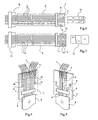
- connection device thus makes it possible to produce an electrical connection device as represented for example in FIGS. Figures 6 and 7 .
- These electrical connection devices are particularly well suited for use in rotating contacts of steering columns of a vehicle or in controls under the steering wheel of a vehicle. It is often necessary to obtain in the above-mentioned applications a minimum space requirement for electrical connection devices which, according to the invention, meet these technical requirements.
Abstract
Description
La présente invention se rapporte au domaine technique des dispositifs de liaison et de connexion électriques. On utilise ce genre de dispositifs de liaison et de connexion notamment dans des contacteurs tournants que l'on retrouve par exemple dans des colonnes de direction d'un véhicule.The present invention relates to the technical field of electrical connection and connection devices. This kind of connection and connection devices are used in particular in rotary contactors found for example in steering columns of a vehicle.
Ces contacts tournants comprennent souvent un ensemble de câbles plats souples présentant chacun des pistes conductrices surmoulées. On connaît ainsi des câbles plats standards présentant six pistes conductrices (6 voies). Il est souvent nécessaire d'avoir pour un contacteur tournant une entrée sur le dispositif de liaison à douze voies, en l'occurrence deux entrées à six voies chacune et une sortie à douze voies qu'il convient de répartir en fonction de différentes fonctionnalités.These rotating contacts often include a set of flexible flat cables each having overmolded conductive tracks. Standard flat cables having six conductive tracks (6 channels) are thus known. It is often necessary for an ignition switch to have an input on the twelve-way link device, in this case two inputs with six channels each and a twelve-channel output which should be distributed according to different functionalities.
Afin d'optimiser la fabrication et le montage de tels câbles plats, dans un espace réduit, il est préférable que les deux câbles plats à six voies restent indépendants l'un de l'autre. Avec l'utilisation de câbles plats standards de six voies chacun, il est impossible d'obtenir une sortie présentant un nombre de douze voies attribuables à différentes fonctionnalités.In order to optimize the manufacture and assembly of such flat cables in a small space, it is preferable that the two flat six-way cables remain independent of one another. With the use of standard flat cables of six channels each, it is impossible to obtain an output having a number of twelve channels attributable to different functionalities.
Pour certaines de ces fonctionnalités, notamment des airbags dans un véhicule, il est en outre exigé par les normes de sécurité qu'il existe une continuité électrique dans l'ensemble de la liaison électrique. Ceci impose des contraintes additionnelles dans la conception et dans l'assemblage du dispositif de liaison électrique.For some of these features, including airbags in a vehicle, it is also required by the safety standards that there is electrical continuity throughout the electrical connection. This imposes additional constraints in the design and assembly of the electrical connection device.
Le but de la présente invention vise à réaliser une liaison électrique ne présentant pas les inconvénients précités en augmentant notamment le nombre de possibilités d'utilisation et de liaisons électriques tout en respectant le cas échéant les normes de sécurité.The object of the present invention is to provide an electrical connection does not have the aforementioned drawbacks by increasing the number of possible uses and electrical connections while respecting where appropriate the safety standards.
Un autre but de la présente invention vise également à faciliter les opérations de montage/démontage notamment dans des endroits difficilement accessibles, tels que commande sous volant ou contacts tournants de colonne de direction de véhicule.Another object of the present invention is also to facilitate assembly / disassembly operations especially in hard to reach places, such as steering wheel control or rotating vehicle steering column contacts.
Le document
Cet inconvénient est résolu par la présente invention, qui vise également à éviter la conception et la fabrication d'éléments de liaison électriques particuliers en vue de répondre à des contraintes particulières et d'utiliser au mieux des éléments standards existants.This disadvantage is solved by the present invention, which also aims to avoid the design and manufacture of particular electrical connection elements to meet specific constraints and best use existing standard elements.
La présente invention concerne un dispositif de connexion électrique.
Selon l'invention, le dispositif de connexion électrique comprend :
- une première et une seconde grilles de connexion, pourvue chacune d'un nombre donné de bornes d'entrée et de bornes de sortie, et de pistes conductrices ;
- des moyens d'assemblage entre elles des deux grilles de connexion ;
- les pistes conductrices étant apparentes sur une face interne des grilles de connexion ; et
- des moyens de transfert de pistes conductrices attribuant, après assemblage, un nombre différent de bornes de sortie aux grilles de connexion ;
- les moyens de transfert comportant au moins une piste conductrice partielle s'étendant entre la borne d'entrée correspondante et une extrémité apparente et accessible sur la face interne de la seconde grille, et au moins une piste conductrice complémentaire s'étendant entre la borne de sortie correspondante et une extrémité apparente et accessible sur la face interne de la première grille, lesdites extrémités de pistes étant en contact mutuel après assemblage des grilles de connexion ;
- chaque borne d'entrée étant reliée électriquement à au moins une borne de sortie via les pistes conductrices.
According to the invention, the electrical connection device comprises:
- first and second connection grids, each provided with a given number of input terminals and output terminals, and conductive tracks;
- connecting means between them of the two connection grids;
- the conductive tracks being visible on an internal face of the connection grids; and
- conductive track transfer means allocating, after assembly, a different number of output terminals to the connection grids;
- the transfer means comprising at least one partial conductive track extending between the corresponding input terminal and an apparent end accessible on the internal face of the second gate, and at least one complementary conductive track extending between the terminal of corresponding output and an apparent end and accessible on the inner face of the first gate, said track ends being in mutual contact after assembly of the connection grids;
- each input terminal being electrically connected to at least one output terminal via the conductive tracks.
Selon un second mode de réalisation de l'invention, le dispositif de connexion électrique comprend :
- une première et une seconde grilles de connexion, pourvue chacune d'un nombre donné de bornes d'entrée et de bornes de sortie, chaque borne d'entrée étant reliée électriquement à au moins une borne de sortie via des pistes conductrices ;
- des moyens d'assemblage entre elles des deux grilles de connexion ;
- les pistes conductrices étant apparentes sur une face interne des grilles de connexion ;
- des moyens de transfert de pistes conductrices attribuant, après assemblage, un nombre différent de bornes de sortie aux grilles de connexion ;
- au moins une piste conductrice s'étendant en continuité électrique d'une part entre les bornes d'entrée et de sortie correspondantes, et d'autre part entre la borne d'entrée correspondante et une extrémité apparente et accessible sur la face interne de la seconde grille, présentant ainsi une configuration à deux branches ;
- les moyens de transfert comportent au moins une piste conductrice complémentaire s'étendant entre la borne de sortie correspondante et une extrémité apparente et accessible sur la face interne de là première grille, lesdites extrémités de pistes étant en contact mutuel après assemblage des grilles de connexion.
- first and second connection grids, each provided with a given number of input terminals and output terminals, each input terminal being electrically connected to at least one output terminal via conductive tracks;
- connecting means between them of the two connection grids;
- the conductive tracks being visible on an internal face of the connection grids;
- conductive track transfer means allocating, after assembly, a different number of output terminals to the connection grids;
- at least one conductive track extending in electrical continuity on the one hand between the corresponding input and output terminals, and on the other hand between the corresponding input terminal and an apparent end accessible on the internal face of the second grid, thus having a configuration with two branches;
- the transfer means comprise at least one complementary conductive track extending between the corresponding output terminal and an apparent end accessible on the inner face of there first grid, said track ends being in mutual contact after assembly of the connection grids.
Selon un exemple de réalisation, les grilles de connexion, une fois assemblées, sont utilisables au choix avec un nombre de bornes de sortie identique ou différent.According to an exemplary embodiment, the connection grids, once assembled, can optionally be used with an identical or different number of output terminals.
Selon un exemple de réalisation, les grilles de connexion sont montées, par exemple par clipsage, sur une pièce support isolante électrique.According to an exemplary embodiment, the connection grids are mounted, for example by clipping, on an electrical insulating support piece.
Selon un exemple de réalisation, les pistes conductrices sont au moins partiellement intégrées dans un support en matière isolante électrique, lequel présente des orifices dans lesquels débouchent lesdites pistes conductrices afin de réaliser les bornes d'entrée et de sortie.According to an exemplary embodiment, the conductive tracks are at least partially integrated in a support of electrical insulating material, which has orifices into which said conductive tracks open to produce the input and output terminals.
Selon un exemple de réalisation, les pistes conductrices sont au moins partiellement recouvertes par une couche isolante électrique.According to an exemplary embodiment, the conductive tracks are at least partially covered by an electrical insulating layer.
Selon un exemple de réalisation, la branche s'étendant entre la borne d'entrée ou de sortie et respectivement l'extrémité de la piste correspondante d'une des grilles présente une élasticité améliorant le contact avec l'extrémité de piste de l'autre grille.According to an exemplary embodiment, the branch extending between the input or output terminal and respectively the end of the corresponding track of one of the grids has an elasticity improving contact with the end of the track of the other wire rack.
Selon un exemple de réalisation, les extrémités de pistes sont solidarisées entre elles par un point de soudure, après l'assemblage des grilles de connexion.According to an exemplary embodiment, the ends of the tracks are joined to each other by a weld point, after assembly of the connection grids.
Selon un exemple de réalisation, la première grille de connexion présente six bornes d'entrée et quatre bornes de sortie, la seconde grille présentant six bornes d'entrée et huit bornes de sortie, lesdites bornes de sortie étant adaptées notamment pour l'engagement de fils électriques.According to an exemplary embodiment, the first lead frame has six input terminals and four output terminals, the second gate having six input terminals and eight output terminals, said output terminals being adapted in particular for the commitment of Electric wires.
La présente invention concerne également un dispositif de liaison électrique comprenant deux câbles plats à six pistes conductrices chacun et reliés à l'une de leurs extrémités à un dispositif de connexion conforme à celui décrit ci-dessus.The present invention also relates to an electrical connection device comprising two flat cables with six conductive tracks each and connected at one of their ends to a connection device according to that described above.
La présente invention concerne par ailleurs également une commande sous volant d'une colonne de direction d'un véhicule comportant un dispositif de liaison électrique conforme à celui décrit ci-dessus.The present invention also relates to a steering wheel control of a steering column of a vehicle comprising an electrical connection device as described above.
D'autres caractéristiques et avantages ressortiront également de la description détaillée figurant ci-après donnée à titre d'exemple en référence aux dessins annexés, dans lesquels :
- la
figure 1 est une représentation d'un dispositif de connexion standard connu en tant que tel ; - les
figures 2 et 3 représentent chacune un élément constitutif d'un exemple de réalisation d'un dispositif de connexion électrique conforme à l'invention ; - les
figures 4 et 5 représentent un autre exemple de réalisation d'éléments constitutifs permettant de réaliser un dispositif de connexion électrique conforme l'invention ; - les
figures 6 et 7 représentent un exemple de réalisation d'un dispositif de liaison électrique conforme à l'invention.
- the
figure 1 is a representation of a standard connection device known as such; - the
Figures 2 and 3 each represent a constituent element of an exemplary embodiment of an electrical connection device according to the invention; - the
Figures 4 and 5 represent another embodiment of constituent elements for producing an electrical connection device according to the invention; - the
Figures 6 and 7 represent an embodiment of an electrical connection device according to the invention.
Le dispositif de connexion électrique de la
Les
Le dispositif de connexion comprend également des moyens d'assemblage (non représentés) entre elles des deux grilles de connexion 1 et 2.The connection device also comprises connecting means (not shown) between them of the two
Il est possible d'engager dans les bornes d'entrée 3 l'extrémité d'un câble plat 6 souple, pourvu de pistes conductrices 5. Les bornes de sortie 4 sont en outre configurées pour permettre l'engagement de câbles électriques 7. D'autres éléments de liaison électriques tels qu'un peigne, peuvent également être prévus pour être engagés dans les bornes de sortie (4).It is possible to engage in the
Le dispositif de connexion conforme à l'invention comporte également des moyens de transfert de pistes conductrices 5, attribuant après assemblage des grilles de connexion 1 et 2; un nombre différent de bornes de sortie 4 aux grilles de connexion 1 et 2. On obtient ainsi, en se reportant par exemple aux
Selon l'exemple de réalisation représenté par exemple aux
Selon un exemple de réalisation, les grilles de connexion 1 et 2 sont montées par exemple par clipsage sur une pièce support isolante électrique. Les grilles de connexion 1 et 2 peuvent ainsi venir enserrer, sous forme de structure sandwich, la pièce support. Les pistes conductrices 5 et les grilles de connexion 1 et 2 sont au moins partiellement intégrées dans un support en matière isolante électrique, lequel présente des orifices dans lesquels débouchent lesdites pistes conductrices 5 afin de réaliser les bornes d'entrée 3 et de sortie 4. Le support en matière isolante électrique est par exemple à base de Polyamides chargés d'un matériau plastique, par exemple référencé par PA 6.6 GF 30.According to an exemplary embodiment, the
Les pistes conductrices 5 sont par exemple apparentes sur une face interne des grilles de connexion 1 et 2. Les pistes conductrices 5 sont de préférence au moins partiellement recouvertes par une couche isolante électrique. On évite ainsi des risques de court-circuit lorsque les grilles de connexion 1 et 2 sont assemblées directement sans pièce support réalisant l'interface.The
Les moyens de transfert comportent par exemple au moins une piste conductrice partielle 8 s'étendant entre la borne d'entrée 3 correspondante et une extrémité apparente et accessible 9 sur la face interne de la seconde grille de connexion 2.The transfer means comprise for example at least one partial
Les moyens de transfert comportent également au moins une piste conductrice complémentaire 10 s'étendant entre la borne de sortie 4 correspondante et une extrémité apparente et accessible 12 complémentaire sur la face interne de la première grille 1. Les extrémités de pistes 9 et 12 sont alors en contact après l'assemblage des grilles de connexion 1 et 2. On obtient ainsi avec deux câbles plats 6 standards, présentant six voies (six pistes conductrices 5) chacun, une configuration dans laquelle le dispositif de connexion conforme à l'invention, constituant une des extrémités des câbles plats 6, permet d'obtenir une solution équivalente à l'utilisation d'un câbles plat 6 à quatre voies et d'un câble plat 6 complémentaire à huit voies. On pourra par exemple se reporter aux
On obtient ainsi l'avantage d'avoir en combinaison d'une part les pistes conductrices 5 présentant une parfaite continuité électrique et satisfaisant par conséquent à des normes de sécurité en vigueur comme c'est le cas par exemple pour le fonctionnement d'organes de sécurité tels que des airbags, et d'autre part des pistes conductrices 5 dont la continuité électrique ne nécessite pas de satisfaire à des critères de sécurité aussi élevés, notamment dans la commande de fonctionnalité telle qu'une radio.This gives the advantage of having in combination on the one hand the
On peut par exemple relier la seconde grille de connexion 2 électriquement à des airbags et la première grille de connexion 1 à un dispositif de commande ou de contrôle d'un autoradio.For example, it is possible to connect the
Dans le dispositif de connexion électrique représenté par exemple aux
Selon un exemple de réalisation, la branche additionnelle 17 ou la piste conductrice partielle 8 ou la piste complémentaire 10 présente une élasticité améliorant le contact entre les extrémités de piste 9 et 12.According to an exemplary embodiment, the
Les extrémités de piste 9 et 12 sont par exemple solidarisées entre elles par un point de soudure après l'assemblage des grilles de connexion 1 et 2. Ces dernières présentent avantageusement un dégagement de matière ou une fenêtre permettant d'accéder aux extrémités de piste 9 et 12 de manière à réaliser l'opération de soudure.The ends of the
Selon un exemple de réalisation et d'utilisation d'un dispositif conforme à l'invention, la première grille 1 présente six bornes d'entrée 3 et huit bornes de sortie 4, tandis que la seconde grille de connexion 2 présente six bornes d'entrée 3 et quatre bornes de sortie 4.According to an exemplary embodiment and use of a device according to the invention, the
L'ensemble des bornes de sortie sont par exemple adaptées notamment à l'engagement de fils électriques 7.The set of output terminals are for example adapted in particular to the engagement of
Le dispositif de connexion conforme à l'invention permet ainsi de réaliser un dispositif de liaison électrique tel que représenté par exemple aux
Claims (10)
- Electrical connection device comprising:- a first (1) and a second (2) connection grid, each provided with a given number of input terminals (3), of output terminals (4) and of conductive tracks (5);- means for assembling the two connection grids (1, 2) together;- the conductive tracks (5) being visible on an inside face of the connection grids (1, 2); and- conductive track (5) transfer means giving, after assembly, a different number of output terminals (4) to the connection grids (1, 2);- the transfer means including at least one partial conductive track (8) extending between the corresponding input terminal (3) and a visible and accessible end (9) on the inside face of the second grid (2), and at least one complementary conductive track (10) extending between the corresponding output terminal (4) and a visible and accessible end (12) on the inside face of the first grid (1), the said track ends (9, 12) being in mutual contact after assembly of the connection grids (1, 2);- each input terminal (3) being electrically connected to at least one output terminal (4) via the conductive tracks (5, 8, 10).
- Electrical connection device comprising:- a first (1) and a second (2) connection grid, each provided with a given number of input terminals (3) and output terminals (4), each input terminal (3) being electrically connected to at least one output terminal (4) via conductive tracks (5);- means for assembling the two connection grids (1, 2) together;- the conductive tracks (5) being visible on an inside face of the connection grids (1, 2);- conductive track (5) transfer means giving, after assembly, a different number of output terminals (4) to the connection grids (1, 2);- at least one conductive track (5) extending with electrical continuity on the one hand between the corresponding input (3) and output (4) terminals, and on the other between the corresponding input terminal (3) and a visible and accessible end (9) on the inside face of the second grid (2), thus presenting a configuration with two branches (5 and 17);- the transfer means include at least one complementary conductive track (10) extending between the corresponding output terminal (4) and a visible and accessible end (12) on the inside face of the first grid (1), the said track ends (9, 12) being in mutual contact after assembly of the connection grids (1, 2).
- Electrical connection device as described in claim 1 or 2, characterised by the fact that the connection grids (1, 2) are mounted, for example by snap-fit, on an electrically insulating support piece.
- Electrical connection device as described in one of claims 1 to 3, characterised by the fact that the conductive tracks (5) are at least partially integrated in a support made of electrically insulating material, which presents orifices in which the said conductive tracks (5) emerge in order to form the input (3) and output (4) terminals.
- Connection device as described in claim 4, characterised by the fact that the conductive tracks (5) are at least partially covered by an electrically insulating layer.
- Connection device as described in one of claims 1 to 5, characterised by the fact that the branch (8, 10, 17) extending between the input (3) or output (4) terminal and the corresponding track end (9) or (12) respectively of at least one of the grids (1, 2), presents an elasticity improving contact with the track end (9, 12) of the other grid (1, 2).
- Electrical connection device as described in any one of claims 1 to 6, characterised by the fact that the track ends (9, 12) are joined together by a spot of solder, after assembly of the connection grids (1, 2).
- Connection device as described in any one of claims 1 to 7, characterised by the fact that the first connection grid (1) presents six input terminals (3) and four output terminals (4), the second connection grid (2) presenting six input terminals (3) and eight output terminals (4), the said output terminals (4) being in particular suitable for engagement of electrical wires (7).
- Electrical connection device comprising two flat cables (6) with six conductive tracks (5) each and connected at one of their ends to a connection device as described in any one of claims 1 to 8.
- Control mounted under the steering wheel of a vehicle including an electrical connection device as described in claim 9.
Applications Claiming Priority (2)
| Application Number | Priority Date | Filing Date | Title |
|---|---|---|---|
| FR0405963 | 2004-06-02 | ||
| FR0405963A FR2871303B1 (en) | 2004-06-02 | 2004-06-02 | ELECTRICAL CONNECTION DEVICE |
Publications (2)
| Publication Number | Publication Date |
|---|---|
| EP1603199A1 EP1603199A1 (en) | 2005-12-07 |
| EP1603199B1 true EP1603199B1 (en) | 2010-04-14 |
Family
ID=34942736
Family Applications (1)
| Application Number | Title | Priority Date | Filing Date |
|---|---|---|---|
| EP05360004A Not-in-force EP1603199B1 (en) | 2004-06-02 | 2005-01-31 | Electrical connecting device |
Country Status (4)
| Country | Link |
|---|---|
| EP (1) | EP1603199B1 (en) |
| AT (1) | ATE464677T1 (en) |
| DE (1) | DE602005020549D1 (en) |
| FR (1) | FR2871303B1 (en) |
Families Citing this family (1)
| Publication number | Priority date | Publication date | Assignee | Title |
|---|---|---|---|---|
| CN102447178B (en) * | 2010-10-15 | 2014-11-19 | 易鼎股份有限公司 | Opposed plugging connector for soft cable and wire |
Family Cites Families (2)
| Publication number | Priority date | Publication date | Assignee | Title |
|---|---|---|---|---|
| US5421741A (en) * | 1993-08-20 | 1995-06-06 | Berg Technology, Inc. | Electrical connection assembly |
| US6575772B1 (en) * | 2002-04-09 | 2003-06-10 | The Ludlow Company Lp | Shielded cable terminal with contact pins mounted to printed circuit board |
-
2004
- 2004-06-02 FR FR0405963A patent/FR2871303B1/en not_active Expired - Fee Related
-
2005
- 2005-01-31 DE DE602005020549T patent/DE602005020549D1/en active Active
- 2005-01-31 AT AT05360004T patent/ATE464677T1/en not_active IP Right Cessation
- 2005-01-31 EP EP05360004A patent/EP1603199B1/en not_active Not-in-force
Also Published As
| Publication number | Publication date |
|---|---|
| ATE464677T1 (en) | 2010-04-15 |
| DE602005020549D1 (en) | 2010-05-27 |
| EP1603199A1 (en) | 2005-12-07 |
| FR2871303B1 (en) | 2006-08-18 |
| FR2871303A1 (en) | 2005-12-09 |
Similar Documents
| Publication | Publication Date | Title |
|---|---|---|
| FR2571203A1 (en) | ELECTRICAL BEAM WITH CIRCUIT PRINTED FOR AUTOMOBILE | |
| FR2967845A1 (en) | ARCHITECTURE OF INTERCONNECTED ELECTRONIC POWER MODULES FOR A ROTATING ELECTRIC MACHINE AND ROTATING ELECTRIC MACHINE COMPRISING SUCH AN ARCHITECTURE | |
| FR2916933A1 (en) | DEVICE FOR ELECTRICAL CONNECTION BETWEEN AN ELECTRICAL POWER SOURCE AND AN ELECTRICAL RADIATOR, AND A METHOD OF MAKING SUCH A CONNECTING DEVICE | |
| EP2643919B1 (en) | Method for interconnecting electronic power modules of a rotary electric machine and assembly of interconnected power modules obtained using said method | |
| EP1902483B1 (en) | Interconnection system for an energy storage assembly | |
| EP3345270B1 (en) | Electric current distribution system for a vehicle | |
| EP3238224B1 (en) | Fuse box for motor vehicle | |
| EP3177123A1 (en) | Mounting of an electronic card, assembly of an electronic card and such a mounting, voltage converter comprising same, and electric machine for motor vehicle comprising same | |
| EP1603199B1 (en) | Electrical connecting device | |
| FR2589636A1 (en) | REMOVABLE CONNECTOR BLOCK FOR USE IN A CONNECTOR ASSEMBLY | |
| FR2855710A1 (en) | Control apparatus for motor vehicle, has spacer blocked between printed circuit boards to electrically connect boards, and connection pins of electronic components contacting with one board based on spacer arrangement | |
| WO2008000931A1 (en) | Electronic card provided with a two-part connector and method of manufacturing such a card | |
| FR2525065A1 (en) | Matrix interconnection system for joining circuit nodes - uses grid of conducting strips into which discontinuous can be introduced to form specific conduction paths | |
| EP0488894B1 (en) | Connection system for removable device | |
| EP0101359A1 (en) | Connector box | |
| EP3672382B1 (en) | Pressing element, assembly and electrical equipment | |
| EP1096843B1 (en) | Power switching device | |
| FR3083375A1 (en) | GRID FOR INTERFACE CONNECTOR | |
| EP1849660A2 (en) | Electrical supply device and connector implemented in such a supply device | |
| FR2983647A1 (en) | Assembly for contact grid of power module in low voltage inverter switch, has isolated conductors that are relative with each other, and contact pads forming ends of one of conductor frame contact pads of other conductor | |
| FR3088492A1 (en) | BRUSH HOLDER OF ROTATING ELECTRIC MACHINE PROVIDED WITH AN ELECTRONIC CONTROL CIRCUIT WITH INTEGRATED TRACKS | |
| EP1443602A1 (en) | Electrical connector for connecting a cable between two car bodies of a railway vehicle | |
| FR3112666A1 (en) | Backup battery with electrical connector | |
| EP3499540A1 (en) | Electrical appliance to establish or interrupt the current in an electric circuit | |
| EP3651273A1 (en) | Device for electrical connection of the downstream terminals of an electrical protection device |
Legal Events
| Date | Code | Title | Description |
|---|---|---|---|
| PUAI | Public reference made under article 153(3) epc to a published international application that has entered the european phase |
Free format text: ORIGINAL CODE: 0009012 |
|
| 17P | Request for examination filed |
Effective date: 20050210 |
|
| AK | Designated contracting states |
Kind code of ref document: A1 Designated state(s): AT BE BG CH CY CZ DE DK EE ES FI FR GB GR HU IE IS IT LI LT LU MC NL PL PT RO SE SI SK TR |
|
| AX | Request for extension of the european patent |
Extension state: AL BA HR LV MK YU |
|
| AKX | Designation fees paid |
Designated state(s): AT BE BG CH CY CZ DE DK EE ES FI FR GB GR HU IE IS IT LI LT LU MC NL PL PT RO SE SI SK TR |
|
| 17Q | First examination report despatched |
Effective date: 20080225 |
|
| GRAP | Despatch of communication of intention to grant a patent |
Free format text: ORIGINAL CODE: EPIDOSNIGR1 |
|
| GRAS | Grant fee paid |
Free format text: ORIGINAL CODE: EPIDOSNIGR3 |
|
| GRAA | (expected) grant |
Free format text: ORIGINAL CODE: 0009210 |
|
| AK | Designated contracting states |
Kind code of ref document: B1 Designated state(s): AT BE BG CH CY CZ DE DK EE ES FI FR GB GR HU IE IS IT LI LT LU MC NL PL PT RO SE SI SK TR |
|
| REG | Reference to a national code |
Ref country code: GB Ref legal event code: FG4D Free format text: NOT ENGLISH |
|
| REG | Reference to a national code |
Ref country code: CH Ref legal event code: EP |
|
| REG | Reference to a national code |
Ref country code: IE Ref legal event code: FG4D Free format text: LANGUAGE OF EP DOCUMENT: FRENCH |
|
| REF | Corresponds to: |
Ref document number: 602005020549 Country of ref document: DE Date of ref document: 20100527 Kind code of ref document: P |
|
| REG | Reference to a national code |
Ref country code: NL Ref legal event code: VDEP Effective date: 20100414 |
|
| LTIE | Lt: invalidation of european patent or patent extension |
Effective date: 20100414 |
|
| PG25 | Lapsed in a contracting state [announced via postgrant information from national office to epo] |
Ref country code: LT Free format text: LAPSE BECAUSE OF FAILURE TO SUBMIT A TRANSLATION OF THE DESCRIPTION OR TO PAY THE FEE WITHIN THE PRESCRIBED TIME-LIMIT Effective date: 20100414 Ref country code: ES Free format text: LAPSE BECAUSE OF FAILURE TO SUBMIT A TRANSLATION OF THE DESCRIPTION OR TO PAY THE FEE WITHIN THE PRESCRIBED TIME-LIMIT Effective date: 20100725 Ref country code: NL Free format text: LAPSE BECAUSE OF FAILURE TO SUBMIT A TRANSLATION OF THE DESCRIPTION OR TO PAY THE FEE WITHIN THE PRESCRIBED TIME-LIMIT Effective date: 20100414 Ref country code: SE Free format text: LAPSE BECAUSE OF FAILURE TO SUBMIT A TRANSLATION OF THE DESCRIPTION OR TO PAY THE FEE WITHIN THE PRESCRIBED TIME-LIMIT Effective date: 20100414 |
|
| REG | Reference to a national code |
Ref country code: IE Ref legal event code: FD4D |
|
| PG25 | Lapsed in a contracting state [announced via postgrant information from national office to epo] |
Ref country code: IS Free format text: LAPSE BECAUSE OF FAILURE TO SUBMIT A TRANSLATION OF THE DESCRIPTION OR TO PAY THE FEE WITHIN THE PRESCRIBED TIME-LIMIT Effective date: 20100814 Ref country code: SI Free format text: LAPSE BECAUSE OF FAILURE TO SUBMIT A TRANSLATION OF THE DESCRIPTION OR TO PAY THE FEE WITHIN THE PRESCRIBED TIME-LIMIT Effective date: 20100414 Ref country code: FI Free format text: LAPSE BECAUSE OF FAILURE TO SUBMIT A TRANSLATION OF THE DESCRIPTION OR TO PAY THE FEE WITHIN THE PRESCRIBED TIME-LIMIT Effective date: 20100414 Ref country code: AT Free format text: LAPSE BECAUSE OF FAILURE TO SUBMIT A TRANSLATION OF THE DESCRIPTION OR TO PAY THE FEE WITHIN THE PRESCRIBED TIME-LIMIT Effective date: 20100414 |
|
| PG25 | Lapsed in a contracting state [announced via postgrant information from national office to epo] |
Ref country code: GR Free format text: LAPSE BECAUSE OF FAILURE TO SUBMIT A TRANSLATION OF THE DESCRIPTION OR TO PAY THE FEE WITHIN THE PRESCRIBED TIME-LIMIT Effective date: 20100715 Ref country code: CY Free format text: LAPSE BECAUSE OF FAILURE TO SUBMIT A TRANSLATION OF THE DESCRIPTION OR TO PAY THE FEE WITHIN THE PRESCRIBED TIME-LIMIT Effective date: 20100421 Ref country code: PL Free format text: LAPSE BECAUSE OF FAILURE TO SUBMIT A TRANSLATION OF THE DESCRIPTION OR TO PAY THE FEE WITHIN THE PRESCRIBED TIME-LIMIT Effective date: 20100414 |
|
| PG25 | Lapsed in a contracting state [announced via postgrant information from national office to epo] |
Ref country code: DK Free format text: LAPSE BECAUSE OF FAILURE TO SUBMIT A TRANSLATION OF THE DESCRIPTION OR TO PAY THE FEE WITHIN THE PRESCRIBED TIME-LIMIT Effective date: 20100414 Ref country code: EE Free format text: LAPSE BECAUSE OF FAILURE TO SUBMIT A TRANSLATION OF THE DESCRIPTION OR TO PAY THE FEE WITHIN THE PRESCRIBED TIME-LIMIT Effective date: 20100414 Ref country code: IE Free format text: LAPSE BECAUSE OF FAILURE TO SUBMIT A TRANSLATION OF THE DESCRIPTION OR TO PAY THE FEE WITHIN THE PRESCRIBED TIME-LIMIT Effective date: 20100414 Ref country code: PT Free format text: LAPSE BECAUSE OF FAILURE TO SUBMIT A TRANSLATION OF THE DESCRIPTION OR TO PAY THE FEE WITHIN THE PRESCRIBED TIME-LIMIT Effective date: 20100816 |
|
| PLBE | No opposition filed within time limit |
Free format text: ORIGINAL CODE: 0009261 |
|
| STAA | Information on the status of an ep patent application or granted ep patent |
Free format text: STATUS: NO OPPOSITION FILED WITHIN TIME LIMIT |
|
| PG25 | Lapsed in a contracting state [announced via postgrant information from national office to epo] |
Ref country code: SK Free format text: LAPSE BECAUSE OF FAILURE TO SUBMIT A TRANSLATION OF THE DESCRIPTION OR TO PAY THE FEE WITHIN THE PRESCRIBED TIME-LIMIT Effective date: 20100414 Ref country code: RO Free format text: LAPSE BECAUSE OF FAILURE TO SUBMIT A TRANSLATION OF THE DESCRIPTION OR TO PAY THE FEE WITHIN THE PRESCRIBED TIME-LIMIT Effective date: 20100414 Ref country code: CZ Free format text: LAPSE BECAUSE OF FAILURE TO SUBMIT A TRANSLATION OF THE DESCRIPTION OR TO PAY THE FEE WITHIN THE PRESCRIBED TIME-LIMIT Effective date: 20100414 |
|
| 26N | No opposition filed |
Effective date: 20110117 |
|
| PG25 | Lapsed in a contracting state [announced via postgrant information from national office to epo] |
Ref country code: IT Free format text: LAPSE BECAUSE OF FAILURE TO SUBMIT A TRANSLATION OF THE DESCRIPTION OR TO PAY THE FEE WITHIN THE PRESCRIBED TIME-LIMIT Effective date: 20100414 |
|
| BERE | Be: lapsed |
Owner name: DELPHI TECHNOLOGIES INC. Effective date: 20110131 |
|
| PG25 | Lapsed in a contracting state [announced via postgrant information from national office to epo] |
Ref country code: MC Free format text: LAPSE BECAUSE OF NON-PAYMENT OF DUE FEES Effective date: 20110131 |
|
| REG | Reference to a national code |
Ref country code: CH Ref legal event code: PL |
|
| GBPC | Gb: european patent ceased through non-payment of renewal fee |
Effective date: 20110131 |
|
| PG25 | Lapsed in a contracting state [announced via postgrant information from national office to epo] |
Ref country code: CH Free format text: LAPSE BECAUSE OF NON-PAYMENT OF DUE FEES Effective date: 20110131 Ref country code: LI Free format text: LAPSE BECAUSE OF NON-PAYMENT OF DUE FEES Effective date: 20110131 |
|
| PG25 | Lapsed in a contracting state [announced via postgrant information from national office to epo] |
Ref country code: GB Free format text: LAPSE BECAUSE OF NON-PAYMENT OF DUE FEES Effective date: 20110131 Ref country code: BE Free format text: LAPSE BECAUSE OF NON-PAYMENT OF DUE FEES Effective date: 20110131 |
|
| PG25 | Lapsed in a contracting state [announced via postgrant information from national office to epo] |
Ref country code: LU Free format text: LAPSE BECAUSE OF NON-PAYMENT OF DUE FEES Effective date: 20110131 |
|
| PG25 | Lapsed in a contracting state [announced via postgrant information from national office to epo] |
Ref country code: BG Free format text: LAPSE BECAUSE OF FAILURE TO SUBMIT A TRANSLATION OF THE DESCRIPTION OR TO PAY THE FEE WITHIN THE PRESCRIBED TIME-LIMIT Effective date: 20100714 Ref country code: TR Free format text: LAPSE BECAUSE OF FAILURE TO SUBMIT A TRANSLATION OF THE DESCRIPTION OR TO PAY THE FEE WITHIN THE PRESCRIBED TIME-LIMIT Effective date: 20100414 |
|
| PG25 | Lapsed in a contracting state [announced via postgrant information from national office to epo] |
Ref country code: HU Free format text: LAPSE BECAUSE OF FAILURE TO SUBMIT A TRANSLATION OF THE DESCRIPTION OR TO PAY THE FEE WITHIN THE PRESCRIBED TIME-LIMIT Effective date: 20100414 |
|
| REG | Reference to a national code |
Ref country code: FR Ref legal event code: PLFP Year of fee payment: 12 |
|
| REG | Reference to a national code |
Ref country code: FR Ref legal event code: PLFP Year of fee payment: 13 |
|
| PGFP | Annual fee paid to national office [announced via postgrant information from national office to epo] |
Ref country code: FR Payment date: 20170125 Year of fee payment: 13 |
|
| PG25 | Lapsed in a contracting state [announced via postgrant information from national office to epo] |
Ref country code: FR Free format text: LAPSE BECAUSE OF NON-PAYMENT OF DUE FEES Effective date: 20180131 |
|
| REG | Reference to a national code |
Ref country code: FR Ref legal event code: ST Effective date: 20180928 |
|
| PGFP | Annual fee paid to national office [announced via postgrant information from national office to epo] |
Ref country code: DE Payment date: 20190123 Year of fee payment: 15 |
|
| REG | Reference to a national code |
Ref country code: DE Ref legal event code: R119 Ref document number: 602005020549 Country of ref document: DE |
|
| PG25 | Lapsed in a contracting state [announced via postgrant information from national office to epo] |
Ref country code: DE Free format text: LAPSE BECAUSE OF NON-PAYMENT OF DUE FEES Effective date: 20200801 |