EP3345270B1 - Electric current distribution system for a vehicle - Google Patents
Electric current distribution system for a vehicle Download PDFInfo
- Publication number
- EP3345270B1 EP3345270B1 EP16766870.6A EP16766870A EP3345270B1 EP 3345270 B1 EP3345270 B1 EP 3345270B1 EP 16766870 A EP16766870 A EP 16766870A EP 3345270 B1 EP3345270 B1 EP 3345270B1
- Authority
- EP
- European Patent Office
- Prior art keywords
- relay
- electrical
- communication bus
- section
- vehicle
- Prior art date
- Legal status (The legal status is an assumption and is not a legal conclusion. Google has not performed a legal analysis and makes no representation as to the accuracy of the status listed.)
- Active
Links
- 238000009826 distribution Methods 0.000 title claims description 23
- 238000004891 communication Methods 0.000 claims description 65
- 230000005540 biological transmission Effects 0.000 claims description 9
- 239000003990 capacitor Substances 0.000 claims description 8
- 239000004065 semiconductor Substances 0.000 claims description 3
- 238000004378 air conditioning Methods 0.000 description 5
- 238000010586 diagram Methods 0.000 description 3
- 230000004913 activation Effects 0.000 description 2
- 238000003780 insertion Methods 0.000 description 2
- 230000037431 insertion Effects 0.000 description 2
- 238000004519 manufacturing process Methods 0.000 description 2
- 230000009467 reduction Effects 0.000 description 2
- 210000002105 tongue Anatomy 0.000 description 2
- 238000003466 welding Methods 0.000 description 2
- RYGMFSIKBFXOCR-UHFFFAOYSA-N Copper Chemical compound [Cu] RYGMFSIKBFXOCR-UHFFFAOYSA-N 0.000 description 1
- 230000003213 activating effect Effects 0.000 description 1
- 238000004026 adhesive bonding Methods 0.000 description 1
- 230000000712 assembly Effects 0.000 description 1
- 238000000429 assembly Methods 0.000 description 1
- 229910052802 copper Inorganic materials 0.000 description 1
- 239000010949 copper Substances 0.000 description 1
- 230000007547 defect Effects 0.000 description 1
- 238000001914 filtration Methods 0.000 description 1
- 238000000034 method Methods 0.000 description 1
- 238000005457 optimization Methods 0.000 description 1
- 230000008569 process Effects 0.000 description 1
- 239000011347 resin Substances 0.000 description 1
- 229920005989 resin Polymers 0.000 description 1
- 238000011144 upstream manufacturing Methods 0.000 description 1
Images


Classifications
-
- B—PERFORMING OPERATIONS; TRANSPORTING
- B60—VEHICLES IN GENERAL
- B60R—VEHICLES, VEHICLE FITTINGS, OR VEHICLE PARTS, NOT OTHERWISE PROVIDED FOR
- B60R16/00—Electric or fluid circuits specially adapted for vehicles and not otherwise provided for; Arrangement of elements of electric or fluid circuits specially adapted for vehicles and not otherwise provided for
- B60R16/02—Electric or fluid circuits specially adapted for vehicles and not otherwise provided for; Arrangement of elements of electric or fluid circuits specially adapted for vehicles and not otherwise provided for electric constitutive elements
- B60R16/023—Electric or fluid circuits specially adapted for vehicles and not otherwise provided for; Arrangement of elements of electric or fluid circuits specially adapted for vehicles and not otherwise provided for electric constitutive elements for transmission of signals between vehicle parts or subsystems
- B60R16/0239—Electronic boxes
-
- B—PERFORMING OPERATIONS; TRANSPORTING
- B60—VEHICLES IN GENERAL
- B60R—VEHICLES, VEHICLE FITTINGS, OR VEHICLE PARTS, NOT OTHERWISE PROVIDED FOR
- B60R16/00—Electric or fluid circuits specially adapted for vehicles and not otherwise provided for; Arrangement of elements of electric or fluid circuits specially adapted for vehicles and not otherwise provided for
- B60R16/005—Electro-mechanical devices, e.g. switched
-
- B—PERFORMING OPERATIONS; TRANSPORTING
- B60—VEHICLES IN GENERAL
- B60R—VEHICLES, VEHICLE FITTINGS, OR VEHICLE PARTS, NOT OTHERWISE PROVIDED FOR
- B60R16/00—Electric or fluid circuits specially adapted for vehicles and not otherwise provided for; Arrangement of elements of electric or fluid circuits specially adapted for vehicles and not otherwise provided for
- B60R16/02—Electric or fluid circuits specially adapted for vehicles and not otherwise provided for; Arrangement of elements of electric or fluid circuits specially adapted for vehicles and not otherwise provided for electric constitutive elements
- B60R16/0207—Wire harnesses
-
- B—PERFORMING OPERATIONS; TRANSPORTING
- B60—VEHICLES IN GENERAL
- B60R—VEHICLES, VEHICLE FITTINGS, OR VEHICLE PARTS, NOT OTHERWISE PROVIDED FOR
- B60R16/00—Electric or fluid circuits specially adapted for vehicles and not otherwise provided for; Arrangement of elements of electric or fluid circuits specially adapted for vehicles and not otherwise provided for
- B60R16/02—Electric or fluid circuits specially adapted for vehicles and not otherwise provided for; Arrangement of elements of electric or fluid circuits specially adapted for vehicles and not otherwise provided for electric constitutive elements
- B60R16/023—Electric or fluid circuits specially adapted for vehicles and not otherwise provided for; Arrangement of elements of electric or fluid circuits specially adapted for vehicles and not otherwise provided for electric constitutive elements for transmission of signals between vehicle parts or subsystems
- B60R16/0238—Electrical distribution centers
Definitions
- the present invention relates to an electronic device and more particularly to an electrical connection box of an electrical current distribution system for a vehicle.
- An electrical connection box for a vehicle is generally an electrical module comprising switching elements allowing the distribution of electrical current to the various accessories of the vehicle.
- This connection box is generally designated by various English terms such as 'Power distribution Box', 'Relay Box', or even 'Junction Box'.
- This box is generally controlled by an electronic control module comprising a microcontroller allowing the acquisition of commands from the user of the vehicle.
- the electrical junction box of a vehicle is the heart of the power distribution and circuit protection in the vehicle.
- the main purpose of the electrical junction box is to provide a centralized location for electrical power and signal distribution for vehicle circuits and their associated electrically controlled components.
- the electrical junction box includes a power distribution system and a printed circuit board for controlling the assembly of fuses and switching devices such as relays.
- the electrical connection box is in electrical communication with a control box.
- the control box is a control unit which processes the commands of the user of the vehicle, and sends signals to the relays contained in the electrical connection box to control the windshield wipers, car lights, defrost ...
- the control box and the electrical connection box are typically two separate assemblies which are located at a distance from each other inside the body of the vehicle.
- the relays are controlled by electronic modules via wired connections to the control box.
- the box of Electrical connection is usually connected to the control box by a harness and standard wiring connectors, which leads to a large number of connectors, connector tabs and copper tracks on the printed circuit board.
- a housing comprises a first housing element and a second housing element.
- the first housing member is provided on one side with a fuse module mounting section having a side opening.
- the second housing member is provided on the same side as the first housing member with a relay module mounting section having a side opening and extending downward.
- a mounting frame for an electrical control unit extends from a bottom wall of the second housing member.
- An electrical control unit is disposed on a second side of a bottom wall of the second housing member and parallel to the mounting section of the relay module.
- a fuse module is attached to the fuse module mounting section to accommodate the fuses.
- a relay module is attached to the relay module mounting section to receive the relays. The fuse module and the relay module which generate heat are arranged on one side of the housing in the vertical direction.
- the invention aims to provide a simple and economical solution to the problems of complexity and cost of existing devices.
- the invention provides an electrical connection box for a vehicle comprising several relays, a relay support, and a connection grid comprising connection sections, each relay comprising electrical connection pins allowing the relay to be plugged into the relay support. and making it possible to connect electrically to the lead frame.
- Each relay has a communication bus interface which is connected to a pin of the relay called the control pin.
- the lead frame has a communication bus section, the control pins of the relays being electrically connected to the communication bus section when the relays are plugged into the socket.
- the section forming the communication bus makes it possible to dispense with the use of a printed circuit board as an electrical support for the bus.
- the use of relays specifically comprising a communication bus interface as well as the use of a section of the connection grid as a communication bus makes it possible to dispense with several independent sections for individual control of each relay.
- the communication bus formed by a section of the lead frame makes it possible to provide a control section common to all the relays, the communication bus allowing individual addressing of each controlled relay.
- the communication bus section may be electrically coupled to an electrical ground section of the lead frame so as to form an electrical capacitor.
- the section forming the communication bus may have a thickness less than the other sections.
- the relay can include an electromechanical switch designed to circulate the electric current distributed to the electric loads of the vehicle or a semiconductor type switch intended to circulate the electric current distributed to the electric loads of the vehicle.
- the communication bus can be of the LIN type.
- the lead frame may have another section forming a differential pair transmission bus with the communication bus section, another relay control pin being electrically connected to the other section forming a differential pair transmission bus.
- the electrical connection box may further include an electrical connection tab to the exterior of the box, the tab being electrically connected to the communication bus section.
- An electrical current distribution system for a vehicle may include a control box provided with a microcontroller, and an electrical connection box as described above.
- the control box may include a communication bus interface electrically connected to the communication bus section of the electrical junction box.
- an electrical connection box 10 for a vehicle comprises a box 12 provided with a first connector 14 allowing it to be connected to an electrical current distribution network to the various electrical loads of the vehicle.
- the electrical connection box 10 also includes relays 16 mounted on the outside of the box 12, thus allowing their accessibility.
- the connection box 10 also includes fuses 18 providing electrical protection of the electrical distribution network to the various electrical loads of the vehicle.
- the connection box 10 comprises a second connector 20 allowing its electrical connection to control signals, the control signals making it possible to ensure the switching of the relays to supply the various electrical loads of the vehicle.
- the junction box 10 may also not include fuses 18 mounted on the casing 12, in particular when the electrical protection of the junction box 10 is provided upstream or downstream of the latter, that is to say is provided by another box connected to the electric current distribution network.
- the number of connectors of the junction box 10 is obviously not limited to two connectors. It depends on the electrical topology of the electrical distribution network; if necessary, a single connector can group together the control signals and the electrical current distribution signals.
- the connectors 14, 20 allowing the connection of the electrical connection box 10 to an electrical current distribution network to the various electrical loads of the vehicle can be replaced by others connection means, such as for example electrical connections of the screwed lug type or by terminals (or contacts) inserted individually in the electrical connection box 10.
- each relay 16 has four pins.
- a first pin 22 and a second pin 24 allow the distribution of electric current to the electric loads of the vehicle.
- a third pin 26 and a fourth pin 28 provide control of relay 16.
- Relay 16 is an electrical load switching component operating as a controllable switch. The pins 22, 24, 26, 28 of each relay 16 allow the interfacing of the relays 16 with the elements of the electrical circuit which transmit the electrical signals necessary for their operation.
- the number of relay pins is not limited to four. Relays 16 comprising for example eight pins in the case of double relays may also be suitable for the invention.
- the pin assignment of the relays does not matter, only the primary functions of a relay, namely the control of the relay and the control of the electrical loads are necessary for the invention.
- each relay 16 comprises a switch 30 of electromechanical type connected between the first pin 22 of the relay and the second pin of the relay 24.
- the switch 30 is also connected to the fourth pin of the relay 28, called the electrical ground pin of the relay.
- the relay 16 also comprises a communication bus interface 32.
- the communication bus interface 32 is connected to the third pin 26 of the relay called the control pin, and on the other hand to the switch 30.
- the communication bus interface 32 is an addressing bus interface allowing all the pins to be connected. controls 26 of the relays 16 between them. The switching of a relay 16 is effective according to an addressing which is specific to the relay to be switched.
- the invention is not limited to electromechanical type switches. Switches of semiconductor type, such as for example power transistors of “MOSFET” type or of “SMART” type of power may be suitable for the invention.
- the electrical connection box 10 for a vehicle comprises the relays 16, the fuses 18, and a leadframe 34.
- the leadframe 34 is also commonly referred to by its English term 'leadframe'.
- the electrical connection box 10 also comprises a relay support 36 and a case back 38 thus forming the housing 12.
- the relay support 36 comprises openings 40 into which the relays 16 and the fuses are plugged in 18.
- the grid connection 34 is equipped with contact pins 42 on which the pins of relays 22, 24, 26, 28 and fuses come into contact so that the pins of relays 22, 24, 26, 28 and fuses are in electrical continuity with the lead frame 34.
- the lead frame 34 and the relay support 36 are therefore arranged so that the pins of the relays 22, 24, 26, 28 can be electrically connected to the lead frame 34.
- the contact pins 42 are of the fork contact 44 or flat contact 46 types, also called female contacts.
- the contact pins 42 are electrically connected to the lead frame 34 by known means such as for example by welding or by insertion.
- the contact pins 42 of the fork contact type 44 are also commonly referred to by their English term 'tuning fork'.
- the relay support 36 and the case back 38 can be in one piece forming the case 12 of the electrical connection box 10.
- the invention is also not limited to a connection box 10 comprising relays 16, other electrical components, such as, for example, power resistors or diodes, can also be plugged into the relay support 36.
- the contact pins 42 can also be of various geometry, their role being to ensure electrical contact. between the components plugged into the relay support 36 and the lead frame 34.
- the lead frame 34 is fixed to the bottom of the case 38.
- the lead frame 34 can be fixed in several known ways such as for example by overmolding in a case of plastic or resin type, or either by gluing.
- the lead frame 34 comprises tabs 48 (or male contacts) which are inserted into the first and second connectors 14, 20 thus ensuring the vehicle's electrical current distribution network and the switching control signals of the relays d 'be in electrical contact with the connection grid 34.
- the first connector 14 comprises a power supply tab 50 of the electrical connection box 10 and load control tabs 52, 54, 56 of the vehicle connected to the connection box 10 electric.
- the second connector 20 comprises a relay control tab 58 and an electrical ground tab 60.
- the electrical loads of the vehicle can be lights, windshield wipers, rear defrost, air conditioning, etc.
- lead frame 34 may be of various geometric shapes.
- a non-coplanar connection grid may prove to be necessary in the case of a connection box 10 comprising a large number of relays.
- the tongues of the connectors can also be independent of the lead frame 34, that is to say that the connector 14 can have its own tongues 48 which can be connected to the lead frame 34 for example by welding or by insertion.
- the lead frame 34 comprises connection sections 62.
- the lead frame 34 comprises in particular an electrical ground section 64, an electrical supply section 66 and vehicle load control sections 68, 70, 72.
- lead frame 34 also has a section forming a communication bus 74.
- the power pins of the relays 22 are electrically connected to the power supply section of the box 66, the electrical ground pins of the relays 28 are connected to the electrical ground section 60.
- the charge control pins of the relays 24 are connected to the various vehicle electrical load control sections 68, 70, 72.
- the control pins of the relays 26 are connected to the section forming the communication bus 74 Likewise the power supply tab of the electrical connection box 50, the electrical earth tab 60, the relay control tab 58 and the battery tabs.
- the hostage of vehicle electrical charges 52, 54, 56 are respectively electrically connected to the power supply section 66, the electrical ground 64, to the communication bus section 74 and to the vehicle load control sections 68, 70, 72.
- the relay control tab 58 is therefore part of the communication bus section 74.
- connection box 10 comprising a section of the connection grid forming a communication bus 74
- the advantages of using an electrical connection box 10 comprising a section of the connection grid forming a communication bus 74 are the simplification of the manufacture and assembly of the electrical connection box 10, the reduction in time. assembly and therefore production costs.
- the use of relays 16 comprising a communication bus interface 32 with the connection box 10 according to the invention also allows an optimization of the electrical architecture of the vehicle, also of course the number of control wires necessary to control the connection box 10 but also on the cost of the electrical connection box 10.
- the cross section of the connection grid forming the communication bus 74 may be of the LIN (Local Interconnect Network) type.
- the communication bus section 74 is also electrically coupled to the electrical ground section 64 so as to form a capacitor 96.
- the communication bus section 74 and the electrical ground section 64 are then sufficiently close to each other. on the other so as to form the electrodes of the capacitor 96.
- the electrical value of the capacitor 96 will be adjustable as a function of the geometric characteristics of the section forming the communication bus 74, of the electric ground section 64 but also of the distance d separating it. these two sections.
- This capacitor 96 allows the filtering of electrical interference on the section forming a communication bus, the electrical interference possibly being for example induced by the electrical interference originating from the environment in which the electrical connection box 10 is located. This capacitor makes it possible to optimize the data transmission speed around a few tens of kbit / s.
- the section forming the communication bus 74 can also have geometric dimensions that are different from the other sections, in particular a smaller thickness than the other sections of the lead frame 34. Indeed, the section forming the communication bus 74 does not carry strong currents. electrical devices such as those required to control vehicle loads.
- the connector 14 can also include other connection tabs.
- capacitor 96 can be an electronic component electrically connected between communication bus section 74 and electrical ground section 64.
- the lead frame 34 may comprise another connection section 76 forming a transmission bus in differential pair with the communication bus section 74, 76.
- this section 76 will have similar geometric characteristics. and will be traced parallel to the communication bus section 74.
- the second connector 20 also includes an additional tab 78 electrically connected to the other connection section 76 forming a differential pair transmission bus 74, 76.
- the transmission bus as a differential pair 74, 76, for example of the CAN (Controller Area Network) type.
- the relays 16 comprise another control pin 80 to which the other connection section 76 forming a differential pair transmission bus is electrically connected.
- the relays 16 therefore include two control pins 26, 80.
- the relays 16 include a differential pair communication bus interface 82 which is connected to the two control pins 26, 80.
- the other features of this embodiment are similar to the embodiment described above.
- an electrical current distribution system 84 for a vehicle may comprise a control box 86, the electrical connection box 10 as described in the previous embodiments and loads of the vehicle 88.
- the control box 86 comprises a microcontroller 90. and a communication bus interface 92.
- the microcontroller 90 and the communication bus interface 92 of the control box are electrically connected to each other.
- the communication bus interface of the control box 92 is electrically connected to an electrical harness of the vehicle 94.
- the electrical harness 94 electrically interfaces with the electrical junction box 10 so that the communication bus interface of the box control 92 is electrically connected to the communication bus section 74 of the electrical junction box 10.
- commands for activating a load of the vehicle 88 are detected by the control unit 86.
- This unit 86 sends to the electrical connection box 10 via the communication bus 74, 94, a switching command of a relay 16 controlling a load 88 to be activated.
- the microcontroller 90 of the control unit 86 recognizes the activation of the control in the passenger compartment of the vehicle.
- the microcontroller 90 then transmits the command to the communication interface of the control unit 92.
- a message is transmitted to the electrical connection box 10 on the control bus. communication 94.
- the message includes the command to activate the air conditioning.
- This message also includes the identity of the relay 16 to be activated. In other words, the message comprises a message which is addressed to a given relay 16, this relay 16 being the one allowing the activation of the air conditioning.
- the communication bus 94 is electrically connected with the section of the connection grid forming the communication bus 74 of the electrical connection box 10. As illustrated above by figure 5 , this electrical connection is made by the relay control tab 58 of the second connector 20, this tab forming part of the section forming the communication bus 74.
- the relay communication bus interfaces 32 connected to the section forming the communication bus 74 receive the control circulating on the section forming the communication bus 74.
- the relays 16 whose identity is not that addressed by the message do not activate.
- the relay 16 of the electrical connection box 10 for which the message is addressed closes its switch 30 so that the power supply to the electrical connection box 50, supplies the electrical load 88 concerned, namely in this example the system of air conditioning. In other words, when the switch 30 of the relay 16 is closed, the electric current can flow from the supply of the electric junction box 50 to the electric load 88.
- the advantages of such an electric current distribution system 84 for a vehicle are the possibility of directly diagnosing a possible fault in the load controlled by the relay 16, the overall reduction in consumption of such a. system, its weight and therefore also its cost.
- the faults diagnosed on the load can be of the “short-circuit” type or also of the “open circuit” type.
- These faults are detected by the communication bus interface 32 of the relays 16 and are therefore communicated directly to the control unit 86.
- the control unit makes it possible for example to inform the user of the vehicle to go to a garage owner. to eradicate the defect.
- the consumption of such a system 84 is reduced in comparison with known systems for which a communication bus interface is fixed on a printed circuit board of the electrical connection box.
- the consumption of the electrical current distribution system 84 will depend directly on the number of relays 16 comprising a communication bus interface 32 plugged into the electrical connection box.
- the weight of the system 84 is also reduced since the system does not need a printed circuit board.
Description
La présente invention concerne un dispositif électronique et plus particulièrement une boîte de raccordement électrique d'un système de distribution de courant électrique pour véhicule.The present invention relates to an electronic device and more particularly to an electrical connection box of an electrical current distribution system for a vehicle.
Une boîte de raccordement électrique pour véhicule est généralement un module électrique comprenant des éléments de commutation permettant la distribution de courant électrique aux différents accessoires du véhicule. Cette boîte de raccordement est généralement désignée par différents termes anglophones tels que 'Power distribution Box', 'Relay Box', ou encore 'Junction Box'. Cette boîte est généralement commandée par un module électronique de commande comprenant un microcontrôleur permettant l'acquisition des commandes de l'utilisateur du véhicule.An electrical connection box for a vehicle is generally an electrical module comprising switching elements allowing the distribution of electrical current to the various accessories of the vehicle. This connection box is generally designated by various English terms such as 'Power distribution Box', 'Relay Box', or even 'Junction Box'. This box is generally controlled by an electronic control module comprising a microcontroller allowing the acquisition of commands from the user of the vehicle.
La boîte de raccordement électrique d'un véhicule est le cœur de la distribution d'énergie et de protection de circuit dans le véhicule. Le but principal de la boîte de raccordement électrique est de fournir un emplacement centralisé pour l'énergie électrique et de distribution de signal pour les circuits de véhicules et leurs composants associés à commande électrique. La boîte de raccordement électrique comprend un système de distribution de puissance et une carte de circuit imprimé pour commander l'assemblage des fusibles et des dispositifs de commutation tels que des relais. La boîte de raccordement électrique est en communication électrique avec un boîtier de commande. Le boîtier de commande est une unité de contrôle qui traite les commandes de l'utilisateur du véhicule, et envoie des signaux aux relais contenus dans la boîte de raccordement électrique pour contrôler les essuie-glaces, les feux de voiture, le dégivrage... Le boîtier de commande et la boîte de raccordement électrique sont typiquement deux ensembles distincts qui sont situées à distance l'une de l'autre à l'intérieur de la caisse du véhicule.The electrical junction box of a vehicle is the heart of the power distribution and circuit protection in the vehicle. The main purpose of the electrical junction box is to provide a centralized location for electrical power and signal distribution for vehicle circuits and their associated electrically controlled components. The electrical junction box includes a power distribution system and a printed circuit board for controlling the assembly of fuses and switching devices such as relays. The electrical connection box is in electrical communication with a control box. The control box is a control unit which processes the commands of the user of the vehicle, and sends signals to the relays contained in the electrical connection box to control the windshield wipers, car lights, defrost ... The control box and the electrical connection box are typically two separate assemblies which are located at a distance from each other inside the body of the vehicle.
De façon conventionnelle, les relais sont commandés par des modules électroniques via des connexions câblées au boîtier de commande. La boîte de raccordement électrique est généralement reliée au boîtier de commande par un faisceau et des connecteurs de câblage standard, ce qui conduit à un grand nombre de connecteurs, de languettes de connecteur et de pistes de cuivre sur la carte de circuit imprimé.Conventionally, the relays are controlled by electronic modules via wired connections to the control box. The box of Electrical connection is usually connected to the control box by a harness and standard wiring connectors, which leads to a large number of connectors, connector tabs and copper tracks on the printed circuit board.
Le document
L'invention vise à proposer une solution simple et économique aux problèmes de complexité et de coût des dispositifs existants.The invention aims to provide a simple and economical solution to the problems of complexity and cost of existing devices.
L'invention propose une boîte de raccordement électrique pour véhicule comprenant plusieurs relais, un support de relais, et une grille de connexion comportant des sections de raccordement, chaque relais comportant des broches de connexion électriques permettant l'enfichage du relais dans le support de relais et permettant de se connecter électriquement à la grille de connexion. Chaque relais comporte une interface de bus de communication qui est raccordé à une broche du relais dite broche de commande. La grille de connexion comporte une section formant bus de communication, les broches de commande des relais étant électriquement connectées à la section formant bus de communication lorsque les relais sont enfichés dans le support.The invention provides an electrical connection box for a vehicle comprising several relays, a relay support, and a connection grid comprising connection sections, each relay comprising electrical connection pins allowing the relay to be plugged into the relay support. and making it possible to connect electrically to the lead frame. Each relay has a communication bus interface which is connected to a pin of the relay called the control pin. The lead frame has a communication bus section, the control pins of the relays being electrically connected to the communication bus section when the relays are plugged into the socket.
La section formant bus de communication permet de s'affranchir de l'utilisation d'une carte à circuit imprimé comme support électrique du bus. L'utilisation de relais comprenant spécifiquement une interface de bus de communication ainsi que l'utilisation d'une section de la grille de connexion comme bus de communication permet de s'affranchir de plusieurs sections indépendantes de commande individuelle de chaque relais. En effet, le bus de communication formé par une section de la grille de connexion permet de proposer une section de commande commune à tous les relais, le bus de communication permettant un adressage individuel de chaque relais commandé.The section forming the communication bus makes it possible to dispense with the use of a printed circuit board as an electrical support for the bus. The use of relays specifically comprising a communication bus interface as well as the use of a section of the connection grid as a communication bus makes it possible to dispense with several independent sections for individual control of each relay. Indeed, the communication bus formed by a section of the lead frame makes it possible to provide a control section common to all the relays, the communication bus allowing individual addressing of each controlled relay.
La section formant bus de communication peut être couplée électriquement à une section de masse électrique de la grille de connexion de sorte à former un condensateur électrique. La section formant bus de communication peut comporter une épaisseur inférieure aux autres sections. Le relais peut comporter un commutateur électromécanique prévu pour faire circuler transitant le courant électrique distribué aux charges électriques du véhicule ou un commutateur de type semi-conducteur prévu pour faire circuler le courant électrique distribué aux charges électriques du véhicule.The communication bus section may be electrically coupled to an electrical ground section of the lead frame so as to form an electrical capacitor. The section forming the communication bus may have a thickness less than the other sections. The relay can include an electromechanical switch designed to circulate the electric current distributed to the electric loads of the vehicle or a semiconductor type switch intended to circulate the electric current distributed to the electric loads of the vehicle.
Le bus de communication peut être de type LIN. La grille de connexion peut comporter une autre section formant un bus de transmission en paire différentielle avec la section formant bus de communication, une autre broche de commande du relais étant connectée électriquement à l'autre section formant un bus de transmission en paire différentielle. La boîte de raccordement électrique peut comprendre de plus une languette de raccordement électrique vers l'extérieur de la boîte, la languette étant électriquement connectée à la section formant bus de communication.The communication bus can be of the LIN type. The lead frame may have another section forming a differential pair transmission bus with the communication bus section, another relay control pin being electrically connected to the other section forming a differential pair transmission bus. The electrical connection box may further include an electrical connection tab to the exterior of the box, the tab being electrically connected to the communication bus section.
Un système de distribution de courant électrique pour véhicule peut comprendre un boîtier de commande muni d'un microcontrôleur, et une boîte de raccordement électrique tel que décrite ci-dessus. Le boîtier de commande peut comporter une interface de bus de communication reliée électriquement à la section formant bus de communication de la boîte de raccordement électrique.An electrical current distribution system for a vehicle may include a control box provided with a microcontroller, and an electrical connection box as described above. The control box may include a communication bus interface electrically connected to the communication bus section of the electrical junction box.
D'autres caractéristiques, buts et avantages de l'invention apparaîtront à la lecture de la description détaillée qui va suivre, et en regard des dessins annexés, donnés à titre d'exemple non limitatif et sur lesquels:
- La
figure 1 est une vue en perspective qui représente schématiquement une boîte de raccordement électrique assemblée selon l'invention. - La
figure 2 est une vue en perspective qui représente schématiquement un relais de la boîte de raccordement électrique de lafigure 1 et qui montre plus particulièrement le dessous du relais. - La
figure 3 est un schéma qui représente l'architecture électrique du relais de lafigure 2 . - La
figure 4 est une vue en perspective éclatée qui représente schématiquement la boîte de raccordement électrique de lafigure 1 . - La
figure 5 est une vue en perspective qui représente schématiquement l'intérieur de la boîte de raccordement électrique de lafigure 1 . - La
figure 6 est une vue en perspective qui représente schématiquement la grille de connexion de la boîte de raccordement électrique de lafigure 1 . - La
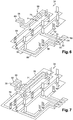
figure 7 est une vue similaire à celle de lafigure 6 qui représente schématiquement une grille de connexion de la boîte de raccordement suivant un deuxième mode de réalisation. - La
figure 8 est un schéma similaire celui de lafigure 3 qui représente l'architecture électrique d'un relais suivant le deuxième mode de réalisation. - La
figure 9 est un bloc diagramme qui représente schématiquement un système de distribution de courant électrique pour véhicule comportant une boîte de raccordement selon l'invention.
- The
figure 1 is a perspective view which schematically shows an assembled electrical connection box according to the invention. - The
figure 2 is a perspective view which schematically shows a relay of the electrical connection box of thefigure 1 and which shows more particularly the underside of the relay. - The
figure 3 is a diagram showing the electrical architecture of the relay of thefigure 2 . - The
figure 4 is an exploded perspective view which schematically shows the electrical connection box of thefigure 1 . - The
figure 5 is a perspective view which schematically shows the interior of the electrical connection box of thefigure 1 . - The
figure 6 is a perspective view which schematically shows the connection grid of the electrical connection box of thefigure 1 . - The
figure 7 is a view similar to that of thefigure 6 which schematically represents a connection grid of the connection box according to a second embodiment. - The
figure 8 is a diagram similar to that offigure 3 which represents the electrical architecture of a relay according to the second embodiment. - The
figure 9 is a block diagram which schematically represents an electric current distribution system for a vehicle comprising a connection box according to the invention.
Selon la
La boîte de raccordement 10 peut également ne pas comprendre de fusibles 18 montés sur le boîtier 12, notamment lorsque la protection électrique de la boîte de raccordement 10 est assurée en amont ou en aval de celle-ci, c'est à dire est assurée par un autre boîtier connecté sur le réseau de distribution du courant électrique. Le nombre de connecteur de la boîte de raccordement 10 n'est évidemment pas limité à deux connecteurs. Cela dépend de la topologie électrique du réseau de distribution électrique ; le cas échéant, un seul connecteur peut regrouper les signaux de commandes et les signaux de distribution de courants électriques. Les connecteurs 14, 20 permettant le raccordement de la boîte de raccordement électrique 10 à un réseau de distribution de courant électrique aux différentes charges électriques du véhicule peuvent être remplacés par d'autres moyens de connexion, tel que par exemple des connexions électriques de type cosses vissées ou par des terminaux (ou contacts) insérés individuellement dans la boîte de raccordement électrique 10.The
Selon la
Le nombre de broche des relais n'est pas limité à quatre. Des relais 16 comprenant par exemple huit broches dans le cas de relais double peuvent également convenir à l'invention. L'affectation des broches des relais n'a pas d'importance, seules les fonctions primaires d'un relais, à savoir la commande du relais et le pilotage des charges électriques sont nécessaire à l'invention.The number of relay pins is not limited to four. Relays 16 comprising for example eight pins in the case of double relays may also be suitable for the invention. The pin assignment of the relays does not matter, only the primary functions of a relay, namely the control of the relay and the control of the electrical loads are necessary for the invention.
Selon la
L'invention ne se limite pas à aux commutateurs de type électromécanique. Des commutateurs de type semi-conducteur, tel que par exemple des transistors de puissances de types 'MOSFET' ou de type 'SMART' de puissance peuvent convenir à l'invention.The invention is not limited to electromechanical type switches. Switches of semiconductor type, such as for example power transistors of “MOSFET” type or of “SMART” type of power may be suitable for the invention.
Selon la
Alternativement, le support de relais 36 et le fond de boîtier 38 peuvent être en une seule pièce formant le boîtier 12 de la boite de raccordement électrique 10. L'invention ne se limité également pas à une boîte de raccordement 10 comprenant des relais 16, d'autres composants électriques, tels que par exemple des résistances de puissances ou des diodes, peuvent également être enfichés dans le support de relais 36. Les broches de contacts 42 peuvent également être de géométrie diverse, leur rôle étant d'assurer le contact électrique entre les composants enfichés dans le support de relais 36 et la grille de connexion 34.Alternatively, the
Selon la
Bien que représentée coplanaire, la grille de connexion 34 peut être de forme géométrique diverse. Une grille de connexion non coplanaire peut s'avérer nécessaire en cas de boite de raccordement 10 comprenant un nombre important de relais. Les languettes des connecteurs peuvent également être indépendantes de la grille de connexion 34, c'est-à-dire que le connecteur 14 peut avoir ces propres languettes 48 pouvant être connectées à la grille de connexion 34 par exemple par soudage ou par insertion.Although shown coplanar,
Selon la
Les avantages de l'utilisation d'une boite de raccordement électrique 10 comprenant une section de la grille de connexion formant bus de communication 74 sont la simplification de la fabrication et de l'assemblage de la boite de raccordement électrique 10, la réduction des temps d'assemblage et donc les coûts de production. L'utilisation des relais 16 comprenant une interface de bus de communication 32 avec la boite de raccordement 10 selon l'invention permet une optimisation également de l'architecture électrique du véhicule, aussi bien sûr le nombre de fils de commande nécessaire au pilotage de la boite de raccordement 10 mais également sur le coût de la boite de raccordement électrique 10.The advantages of using an
La section de la grille de connexion formant bus de communication 74 peut être du type LIN (Local Interconnect Network). De préférence, la section formant bus de communication 74 est également couplée électriquement à la section de masse électrique 64 de sorte à former un condensateur 96. La section formant bus de communication 74 et la section de masse électrique 64 sont alors suffisamment proche l'une de l'autre de sorte à former les électrodes du condensateur 96. La valeur électrique du condensateur 96 sera ajustable en fonction des caractéristiques géométriques de la section formant bus de communication 74, de la section de masse électrique 64 mais également de la distance d séparant ces deux sections. Ce condensateur 96 permet le filtrage de parasites électriques sur la section formant bus de communication, les parasites électriques pouvant être par exemple induits par les interférences électriques issues de l'environnement dans lequel la boîte de raccordement électrique 10 est implantée. Ce condensateur permet d'optimiser la vitesse de transmission des données aux alentours de quelques dizaines de kbit/s. La section formant bus de communication 74 peut également avoir des dimensions géométriques différentes des autres sections, notamment une épaisseur plus faible que les autres sections de la grille de connexion 34. En effet, la section formant bus de communication 74 ne transporte pas de forts courants électriques tels que ceux nécessaire au pilotage des charges du véhicule. Le connecteur 14 peut également comprendre d'autres languettes de connexion. Alternativement, le condensateur 96 peut être un composant électronique connecté électriquement entre la section formant bus de communication 74 et la section de masse électrique 64The cross section of the connection grid forming the
Selon la
Selon la
De façon fonctionnelle, lorsqu'un utilisateur d'un véhicule veut commander une charge électrique 88 telle que par exemple l'air conditionné, le microcontrôleur 90 du boîtier de commande 86 reconnait l'activation de la commande dans l'habitacle du véhicule. Le microcontrôleur 90 transmet alors la commande à l'interface de communication du boîtier de commande 92. Par l'intermédiaire de l'interface de communication du boitier de commande 92, un message est transmis à la boîte de raccordement électrique 10 sur le bus de communication 94. Le message comprend la commande d'activation de l'air conditionné. Ce message comprend également l'identité du relais 16 à activer. En d'autres termes, le message comprend un message qui est adressé à un relais 16 donné, ce relais 16 étant celui permettant l'activation de l'air conditionné. Le bus de communication 94 est relié électriquement avec la section de la grille de connexion formant bus de communication 74 du boitier de raccordement électrique 10. Comme illustré précédemment par la
Les avantages d'un tel système de distribution de courant électrique 84 pour véhicule sont la possibilité de diagnostiquer directement un défaut éventuel de la charge piloté par le relais 16, la réduction de consommation global d'un tel système, son poids et donc également son coût. A titre d'exemple, les défauts diagnostiqués sur la charge peuvent être de type 'court-circuit' ou également de type 'circuit ouvert'. Ces défauts sont détectés par l'interface de bus de communication 32 des relais 16 et sont donc communiquer directement au boîtier de commande 86. Le boîtier de commande permettant par exemple d'informer l'utilisateur du véhicule de se rendre auprès d'un garagiste pour éradiquer le défaut. Egalement la consommation d'un tel système 84, notamment la consommation électrique du bus de communication 74, est réduite en comparaison des systèmes connus pour lesquels une interface de bus de communication est fixée sur une carte à circuit imprimé de la boite de raccordement électrique. Selon l'invention, la consommation du système de distribution de courant électrique 84 dépendra directement du nombre de relais 16 comprenant une interface de bus de communication 32 enfichés dans la boîte de raccordement électrique. Le poids du système 84 est également réduit puisque le système s'affranchi d'une carte à circuit imprimé.The advantages of such an electric
Claims (9)
- An electrical junction box (10) for a vehicle comprising several relays (16), a relay support (36), and a leadframe (34) including junction sections (62), each relay (16) including electrical connection pins (22, 24, 26, 28) allowing the plugging of the relay (16) in the relay support (36) and allowing electrical connection to the leadframe (34), characterized in that each relay (16) includes a communication bus interface (32) which is joined to a pin of the relay called control pin (26), and in that the leadframe (34) includes a section (74) forming a communication bus, the relay control pins (26) being electrically connected to the section (74) forming a communication bus when the relays (16) are plugged into the support (36).
- The electrical junction box (10) for a vehicle according to claim 1 characterized in that the section (74) forming a communication bus is electrically coupled to an electric ground section of the leadframe (64) so as to form an electric capacitor.
- The electrical junction box (10) for a vehicle according to any one of the preceding claims, characterized in that the section (74) forming a communication bus has a thickness smaller than the other sections (68, 70, 72).
- The electrical junction box (10) according to any one of preceding claims, characterized in that the relay (16) includes an electromechanical switch provided to circulate the electric current distributed to the electric loads of the vehicle.
- The electrical junction box (10) according to any one of claims 1 to 3, characterized in that the relay (16) includes a semi-conductor type switch provided to circulate the electric current distributed to the electrical loads of the vehicle.
- The electrical junction box (10) for a vehicle according to any one of the preceding claims, characterized in that the communication bus is of the LIN type.
- The electrical junction box (10) for a vehicle according to any one of claims 1 to 5, characterized in that the leadframe (34) includes another section (76) forming a differential pair transmission bus (74, 76) with the section (74) forming a communication bus, an another relay control pin (80) being electrically connected to the other section (76) forming a differential pair transmission bus (74, 76).
- The electrical junction box (10) for a vehicle according to any one of the preceding claims, characterized in that the electrical junction box (10) further comprises at least one relay control tab (58) directed towards the outside of the box (10), the tab (58) being electrically connected to the section (74) forming a communication bus.
- An electrical power distribution system (84) for a vehicle comprising a control box (86) equipped with a microcontroller (90), characterized in that the system (84) also comprises an electrical junction box (10) according to any one of the preceding claims, and in that the control box (86) includes a communication bus interface (92) electrically connected to the section (74) forming a communication bus of the electrical junction box (10).
Applications Claiming Priority (2)
| Application Number | Priority Date | Filing Date | Title |
|---|---|---|---|
| FR1558228A FR3040833B1 (en) | 2015-09-04 | 2015-09-04 | ELECTRICAL POWER DISTRIBUTION SYSTEM FOR VEHICLE |
| PCT/EP2016/070646 WO2017037192A1 (en) | 2015-09-04 | 2016-09-01 | Electric current distribution system for a vehicle |
Publications (2)
| Publication Number | Publication Date |
|---|---|
| EP3345270A1 EP3345270A1 (en) | 2018-07-11 |
| EP3345270B1 true EP3345270B1 (en) | 2020-11-04 |
Family
ID=55178072
Family Applications (1)
| Application Number | Title | Priority Date | Filing Date |
|---|---|---|---|
| EP16766870.6A Active EP3345270B1 (en) | 2015-09-04 | 2016-09-01 | Electric current distribution system for a vehicle |
Country Status (5)
| Country | Link |
|---|---|
| US (1) | US10562473B2 (en) |
| EP (1) | EP3345270B1 (en) |
| CN (1) | CN108141026B (en) |
| FR (1) | FR3040833B1 (en) |
| WO (1) | WO2017037192A1 (en) |
Families Citing this family (5)
| Publication number | Priority date | Publication date | Assignee | Title |
|---|---|---|---|---|
| EP3496220B1 (en) * | 2016-08-02 | 2023-04-26 | FCA Fiat Chrysler Automóveis Brasil Ltda. | Hybrid energy distribution plant for vehicles |
| CN108909673B (en) * | 2018-07-09 | 2021-03-05 | 钧捷智能(深圳)有限公司 | Intelligent automobile door and window anti-theft alarm system |
| CN110549965A (en) * | 2019-09-30 | 2019-12-10 | 江西优特汽车技术有限公司 | High-voltage distribution box with strong universality |
| FR3109032A1 (en) * | 2020-04-07 | 2021-10-08 | Psa Automobiles Sa | ELECTRICAL CONNECTION BOX EQUIPPED WITH REMOTE RELAYS |
| CN112367771B (en) * | 2020-12-12 | 2022-03-04 | 河南天海电器有限公司 | Circuit board design method of commercial vehicle electrical box and circuit board |
Citations (1)
| Publication number | Priority date | Publication date | Assignee | Title |
|---|---|---|---|---|
| US7733632B2 (en) * | 2007-01-23 | 2010-06-08 | Sumitomo Wiring Systems, Ltd. | Vehicle-mounted electrical junction box |
Family Cites Families (16)
| Publication number | Priority date | Publication date | Assignee | Title |
|---|---|---|---|---|
| JP2989457B2 (en) * | 1993-02-17 | 1999-12-13 | 矢崎総業株式会社 | Meter module |
| JP2920904B2 (en) * | 1994-03-28 | 1999-07-19 | 矢崎総業株式会社 | Meter module assembly |
| DE69734095T2 (en) * | 1996-10-24 | 2006-07-13 | Thomas & Betts International Inc., Sparks | POWER DISTRIBUTION UNIT |
| JP3680603B2 (en) | 1998-12-24 | 2005-08-10 | 住友電装株式会社 | Laminated board |
| EP1018783B1 (en) * | 1999-01-04 | 2003-06-18 | Sumitomo Wiring Systems, Ltd. | Electrical junction box having a bus bar |
| US6642633B1 (en) * | 2001-06-27 | 2003-11-04 | Yazaki North America, Inc. | Power management assembly |
| WO2005013449A1 (en) * | 2003-07-31 | 2005-02-10 | Yazaki Corporation | Junction block |
| JP4161877B2 (en) * | 2003-11-05 | 2008-10-08 | 住友電装株式会社 | Circuit structure, manufacturing method thereof and power distribution unit |
| JP4254600B2 (en) * | 2004-04-01 | 2009-04-15 | 住友電装株式会社 | Electrical junction box |
| JP3888368B2 (en) * | 2004-07-13 | 2007-02-28 | 住友電装株式会社 | Electrical junction box |
| DE102009055717A1 (en) * | 2009-11-26 | 2011-06-01 | Continental Automotive Gmbh | Sensor module and manufacturing method of a sensor module |
| US8982578B2 (en) * | 2010-10-14 | 2015-03-17 | Tyco Electronics Corporation | Connector system and assembly having integrated protection circuitry |
| JP5892505B2 (en) | 2011-06-30 | 2016-03-23 | 矢崎総業株式会社 | Sheet metal member, bus bar, and electrical junction box provided with the bus bar |
| JP6081128B2 (en) * | 2012-10-10 | 2017-02-15 | 三洋電機株式会社 | Power supply device, vehicle including the same, and power storage device |
| DE102013101314A1 (en) * | 2013-02-11 | 2014-08-14 | Phoenix Contact Gmbh & Co. Kg | Safe photovoltaic system |
| US20160026201A1 (en) * | 2013-07-26 | 2016-01-28 | Mohan Vellanki | Systems and methods for controlling electrical devices |
-
2015
- 2015-09-04 FR FR1558228A patent/FR3040833B1/en active Active
-
2016
- 2016-09-01 EP EP16766870.6A patent/EP3345270B1/en active Active
- 2016-09-01 CN CN201680050881.5A patent/CN108141026B/en active Active
- 2016-09-01 US US15/755,287 patent/US10562473B2/en active Active
- 2016-09-01 WO PCT/EP2016/070646 patent/WO2017037192A1/en active Application Filing
Patent Citations (1)
| Publication number | Priority date | Publication date | Assignee | Title |
|---|---|---|---|---|
| US7733632B2 (en) * | 2007-01-23 | 2010-06-08 | Sumitomo Wiring Systems, Ltd. | Vehicle-mounted electrical junction box |
Also Published As
| Publication number | Publication date |
|---|---|
| FR3040833B1 (en) | 2017-09-08 |
| EP3345270A1 (en) | 2018-07-11 |
| CN108141026B (en) | 2020-03-20 |
| FR3040833A1 (en) | 2017-03-10 |
| US20180326930A1 (en) | 2018-11-15 |
| CN108141026A (en) | 2018-06-08 |
| US10562473B2 (en) | 2020-02-18 |
| WO2017037192A1 (en) | 2017-03-09 |
Similar Documents
| Publication | Publication Date | Title |
|---|---|---|
| EP3345270B1 (en) | Electric current distribution system for a vehicle | |
| FR2893456A1 (en) | ELECTRICAL DISTRIBUTION SYSTEM AND MODULAR HIGH POWER INPUT CONTACTOR FOR THE SAME. | |
| FR2491846A1 (en) | FUSE AND DISTRIBUTION BOX FOR MOTOR VEHICLES | |
| FR2808131A1 (en) | ELECTRICAL CONNECTOR | |
| EP2696448B1 (en) | Electrical appliance with communication means mounted on a PCB | |
| EP3238224A1 (en) | Fuse box for motor vehicle | |
| CA2898070A1 (en) | Connection system for protective cards for a distribution system and rack integrating such a system | |
| EP0629957B1 (en) | Bus system with a reduced number of lines and its use | |
| EP1095438A1 (en) | Device for distributing energy between a plurality of electronic modules with possibility of shedding | |
| EP3576975B1 (en) | Electrical connection device with built-in lockout function | |
| CN112867634A (en) | Distribution branch box | |
| FR2513477A1 (en) | ELECTRIC EQUIPMENT OF THE TYPE COMPRISING SEVERAL PRINTED CIRCUIT BOARDS CONNECTED TO A CONNECTION PLAN | |
| FR2996938A1 (en) | Architecture for communication and distribution of electric power in aircraft, has power plug gateway connected to inter-connecting power modules, and power equipment gateway connected to power plug gateway by power modules | |
| EP3516937A1 (en) | Automotive computer housing, corresponding computer and vehicle | |
| FR2859683A1 (en) | Functional equipment control system for vehicle e.g. scooter, has programmable unit that establishes programmable array to connect control parts and equipment, and is arranged between control parts and power switches | |
| EP3887209A1 (en) | Power supply system installed in a vehicle | |
| EP3380365B1 (en) | Electronic device for vehicles powered by two electrical power networks | |
| EP0731001A1 (en) | Electrical power installation for camper or the same | |
| EP0547957A1 (en) | Central electrical unit of a vehicle, particularly of an automobile | |
| EP1603199B1 (en) | Electrical connecting device | |
| FR3109032A1 (en) | ELECTRICAL CONNECTION BOX EQUIPPED WITH REMOTE RELAYS | |
| AU2016200433B1 (en) | Control module for an alternator | |
| FR3020022A1 (en) | DEVICE FOR CONTROLLING LIGHTING AND / OR SIGNALING LAMPS WITH AN ELECTRONIC CONTROL SYSTEM IN A MANUAL LIGHTING CONTROL ARRESTOR | |
| EP2235359B1 (en) | Antitheft device adapter and related antitheft device | |
| FR3000625A1 (en) | Device for electrical supply of electric motor for driving mobile element e.g. door leaf of door, has connection terminals that are connected with auxiliary electrical supply source according to type of automobile battery |
Legal Events
| Date | Code | Title | Description |
|---|---|---|---|
| STAA | Information on the status of an ep patent application or granted ep patent |
Free format text: STATUS: THE INTERNATIONAL PUBLICATION HAS BEEN MADE |
|
| PUAI | Public reference made under article 153(3) epc to a published international application that has entered the european phase |
Free format text: ORIGINAL CODE: 0009012 |
|
| STAA | Information on the status of an ep patent application or granted ep patent |
Free format text: STATUS: REQUEST FOR EXAMINATION WAS MADE |
|
| 17P | Request for examination filed |
Effective date: 20180404 |
|
| AK | Designated contracting states |
Kind code of ref document: A1 Designated state(s): AL AT BE BG CH CY CZ DE DK EE ES FI FR GB GR HR HU IE IS IT LI LT LU LV MC MK MT NL NO PL PT RO RS SE SI SK SM TR |
|
| AX | Request for extension of the european patent |
Extension state: BA ME |
|
| DAV | Request for validation of the european patent (deleted) | ||
| DAX | Request for extension of the european patent (deleted) | ||
| RAP1 | Party data changed (applicant data changed or rights of an application transferred) |
Owner name: APTIV TECHNOLOGIES LIMITED |
|
| STAA | Information on the status of an ep patent application or granted ep patent |
Free format text: STATUS: EXAMINATION IS IN PROGRESS |
|
| 17Q | First examination report despatched |
Effective date: 20190808 |
|
| GRAP | Despatch of communication of intention to grant a patent |
Free format text: ORIGINAL CODE: EPIDOSNIGR1 |
|
| STAA | Information on the status of an ep patent application or granted ep patent |
Free format text: STATUS: GRANT OF PATENT IS INTENDED |
|
| INTG | Intention to grant announced |
Effective date: 20200520 |
|
| GRAS | Grant fee paid |
Free format text: ORIGINAL CODE: EPIDOSNIGR3 |
|
| GRAA | (expected) grant |
Free format text: ORIGINAL CODE: 0009210 |
|
| STAA | Information on the status of an ep patent application or granted ep patent |
Free format text: STATUS: THE PATENT HAS BEEN GRANTED |
|
| AK | Designated contracting states |
Kind code of ref document: B1 Designated state(s): AL AT BE BG CH CY CZ DE DK EE ES FI FR GB GR HR HU IE IS IT LI LT LU LV MC MK MT NL NO PL PT RO RS SE SI SK SM TR |
|
| REG | Reference to a national code |
Ref country code: GB Ref legal event code: FG4D Free format text: NOT ENGLISH |
|
| REG | Reference to a national code |
Ref country code: CH Ref legal event code: EP |
|
| REG | Reference to a national code |
Ref country code: AT Ref legal event code: REF Ref document number: 1332061 Country of ref document: AT Kind code of ref document: T Effective date: 20201115 |
|
| REG | Reference to a national code |
Ref country code: IE Ref legal event code: FG4D Free format text: LANGUAGE OF EP DOCUMENT: FRENCH |
|
| REG | Reference to a national code |
Ref country code: DE Ref legal event code: R096 Ref document number: 602016047228 Country of ref document: DE |
|
| REG | Reference to a national code |
Ref country code: NL Ref legal event code: MP Effective date: 20201104 |
|
| REG | Reference to a national code |
Ref country code: AT Ref legal event code: MK05 Ref document number: 1332061 Country of ref document: AT Kind code of ref document: T Effective date: 20201104 |
|
| PG25 | Lapsed in a contracting state [announced via postgrant information from national office to epo] |
Ref country code: NO Free format text: LAPSE BECAUSE OF FAILURE TO SUBMIT A TRANSLATION OF THE DESCRIPTION OR TO PAY THE FEE WITHIN THE PRESCRIBED TIME-LIMIT Effective date: 20210204 Ref country code: PT Free format text: LAPSE BECAUSE OF FAILURE TO SUBMIT A TRANSLATION OF THE DESCRIPTION OR TO PAY THE FEE WITHIN THE PRESCRIBED TIME-LIMIT Effective date: 20210304 Ref country code: RS Free format text: LAPSE BECAUSE OF FAILURE TO SUBMIT A TRANSLATION OF THE DESCRIPTION OR TO PAY THE FEE WITHIN THE PRESCRIBED TIME-LIMIT Effective date: 20201104 Ref country code: GR Free format text: LAPSE BECAUSE OF FAILURE TO SUBMIT A TRANSLATION OF THE DESCRIPTION OR TO PAY THE FEE WITHIN THE PRESCRIBED TIME-LIMIT Effective date: 20210205 Ref country code: FI Free format text: LAPSE BECAUSE OF FAILURE TO SUBMIT A TRANSLATION OF THE DESCRIPTION OR TO PAY THE FEE WITHIN THE PRESCRIBED TIME-LIMIT Effective date: 20201104 |
|
| PG25 | Lapsed in a contracting state [announced via postgrant information from national office to epo] |
Ref country code: SE Free format text: LAPSE BECAUSE OF FAILURE TO SUBMIT A TRANSLATION OF THE DESCRIPTION OR TO PAY THE FEE WITHIN THE PRESCRIBED TIME-LIMIT Effective date: 20201104 Ref country code: AT Free format text: LAPSE BECAUSE OF FAILURE TO SUBMIT A TRANSLATION OF THE DESCRIPTION OR TO PAY THE FEE WITHIN THE PRESCRIBED TIME-LIMIT Effective date: 20201104 Ref country code: ES Free format text: LAPSE BECAUSE OF FAILURE TO SUBMIT A TRANSLATION OF THE DESCRIPTION OR TO PAY THE FEE WITHIN THE PRESCRIBED TIME-LIMIT Effective date: 20201104 Ref country code: BG Free format text: LAPSE BECAUSE OF FAILURE TO SUBMIT A TRANSLATION OF THE DESCRIPTION OR TO PAY THE FEE WITHIN THE PRESCRIBED TIME-LIMIT Effective date: 20210204 Ref country code: LV Free format text: LAPSE BECAUSE OF FAILURE TO SUBMIT A TRANSLATION OF THE DESCRIPTION OR TO PAY THE FEE WITHIN THE PRESCRIBED TIME-LIMIT Effective date: 20201104 Ref country code: PL Free format text: LAPSE BECAUSE OF FAILURE TO SUBMIT A TRANSLATION OF THE DESCRIPTION OR TO PAY THE FEE WITHIN THE PRESCRIBED TIME-LIMIT Effective date: 20201104 Ref country code: IS Free format text: LAPSE BECAUSE OF FAILURE TO SUBMIT A TRANSLATION OF THE DESCRIPTION OR TO PAY THE FEE WITHIN THE PRESCRIBED TIME-LIMIT Effective date: 20210304 |
|
| REG | Reference to a national code |
Ref country code: LT Ref legal event code: MG9D |
|
| PG25 | Lapsed in a contracting state [announced via postgrant information from national office to epo] |
Ref country code: HR Free format text: LAPSE BECAUSE OF FAILURE TO SUBMIT A TRANSLATION OF THE DESCRIPTION OR TO PAY THE FEE WITHIN THE PRESCRIBED TIME-LIMIT Effective date: 20201104 |
|
| PG25 | Lapsed in a contracting state [announced via postgrant information from national office to epo] |
Ref country code: LT Free format text: LAPSE BECAUSE OF FAILURE TO SUBMIT A TRANSLATION OF THE DESCRIPTION OR TO PAY THE FEE WITHIN THE PRESCRIBED TIME-LIMIT Effective date: 20201104 Ref country code: SM Free format text: LAPSE BECAUSE OF FAILURE TO SUBMIT A TRANSLATION OF THE DESCRIPTION OR TO PAY THE FEE WITHIN THE PRESCRIBED TIME-LIMIT Effective date: 20201104 Ref country code: EE Free format text: LAPSE BECAUSE OF FAILURE TO SUBMIT A TRANSLATION OF THE DESCRIPTION OR TO PAY THE FEE WITHIN THE PRESCRIBED TIME-LIMIT Effective date: 20201104 Ref country code: CZ Free format text: LAPSE BECAUSE OF FAILURE TO SUBMIT A TRANSLATION OF THE DESCRIPTION OR TO PAY THE FEE WITHIN THE PRESCRIBED TIME-LIMIT Effective date: 20201104 Ref country code: SK Free format text: LAPSE BECAUSE OF FAILURE TO SUBMIT A TRANSLATION OF THE DESCRIPTION OR TO PAY THE FEE WITHIN THE PRESCRIBED TIME-LIMIT Effective date: 20201104 Ref country code: RO Free format text: LAPSE BECAUSE OF FAILURE TO SUBMIT A TRANSLATION OF THE DESCRIPTION OR TO PAY THE FEE WITHIN THE PRESCRIBED TIME-LIMIT Effective date: 20201104 |
|
| REG | Reference to a national code |
Ref country code: DE Ref legal event code: R097 Ref document number: 602016047228 Country of ref document: DE |
|
| PG25 | Lapsed in a contracting state [announced via postgrant information from national office to epo] |
Ref country code: DK Free format text: LAPSE BECAUSE OF FAILURE TO SUBMIT A TRANSLATION OF THE DESCRIPTION OR TO PAY THE FEE WITHIN THE PRESCRIBED TIME-LIMIT Effective date: 20201104 |
|
| PLBE | No opposition filed within time limit |
Free format text: ORIGINAL CODE: 0009261 |
|
| STAA | Information on the status of an ep patent application or granted ep patent |
Free format text: STATUS: NO OPPOSITION FILED WITHIN TIME LIMIT |
|
| 26N | No opposition filed |
Effective date: 20210805 |
|
| PG25 | Lapsed in a contracting state [announced via postgrant information from national office to epo] |
Ref country code: NL Free format text: LAPSE BECAUSE OF FAILURE TO SUBMIT A TRANSLATION OF THE DESCRIPTION OR TO PAY THE FEE WITHIN THE PRESCRIBED TIME-LIMIT Effective date: 20201104 Ref country code: AL Free format text: LAPSE BECAUSE OF FAILURE TO SUBMIT A TRANSLATION OF THE DESCRIPTION OR TO PAY THE FEE WITHIN THE PRESCRIBED TIME-LIMIT Effective date: 20201104 |
|
| PG25 | Lapsed in a contracting state [announced via postgrant information from national office to epo] |
Ref country code: SI Free format text: LAPSE BECAUSE OF FAILURE TO SUBMIT A TRANSLATION OF THE DESCRIPTION OR TO PAY THE FEE WITHIN THE PRESCRIBED TIME-LIMIT Effective date: 20201104 |
|
| REG | Reference to a national code |
Ref country code: CH Ref legal event code: PL |
|
| REG | Reference to a national code |
Ref country code: BE Ref legal event code: MM Effective date: 20210930 |
|
| PG25 | Lapsed in a contracting state [announced via postgrant information from national office to epo] |
Ref country code: IS Free format text: LAPSE BECAUSE OF FAILURE TO SUBMIT A TRANSLATION OF THE DESCRIPTION OR TO PAY THE FEE WITHIN THE PRESCRIBED TIME-LIMIT Effective date: 20210304 Ref country code: MC Free format text: LAPSE BECAUSE OF FAILURE TO SUBMIT A TRANSLATION OF THE DESCRIPTION OR TO PAY THE FEE WITHIN THE PRESCRIBED TIME-LIMIT Effective date: 20201104 |
|
| PG25 | Lapsed in a contracting state [announced via postgrant information from national office to epo] |
Ref country code: LU Free format text: LAPSE BECAUSE OF NON-PAYMENT OF DUE FEES Effective date: 20210901 Ref country code: IE Free format text: LAPSE BECAUSE OF NON-PAYMENT OF DUE FEES Effective date: 20210901 Ref country code: BE Free format text: LAPSE BECAUSE OF NON-PAYMENT OF DUE FEES Effective date: 20210930 |
|
| PG25 | Lapsed in a contracting state [announced via postgrant information from national office to epo] |
Ref country code: LI Free format text: LAPSE BECAUSE OF NON-PAYMENT OF DUE FEES Effective date: 20210930 Ref country code: CH Free format text: LAPSE BECAUSE OF NON-PAYMENT OF DUE FEES Effective date: 20210930 |
|
| PG25 | Lapsed in a contracting state [announced via postgrant information from national office to epo] |
Ref country code: HU Free format text: LAPSE BECAUSE OF FAILURE TO SUBMIT A TRANSLATION OF THE DESCRIPTION OR TO PAY THE FEE WITHIN THE PRESCRIBED TIME-LIMIT; INVALID AB INITIO Effective date: 20160901 |
|
| P01 | Opt-out of the competence of the unified patent court (upc) registered |
Effective date: 20230424 |
|
| PG25 | Lapsed in a contracting state [announced via postgrant information from national office to epo] |
Ref country code: CY Free format text: LAPSE BECAUSE OF FAILURE TO SUBMIT A TRANSLATION OF THE DESCRIPTION OR TO PAY THE FEE WITHIN THE PRESCRIBED TIME-LIMIT Effective date: 20201104 |
|
| PGFP | Annual fee paid to national office [announced via postgrant information from national office to epo] |
Ref country code: IT Payment date: 20230927 Year of fee payment: 8 Ref country code: GB Payment date: 20230914 Year of fee payment: 8 |
|
| PGFP | Annual fee paid to national office [announced via postgrant information from national office to epo] |
Ref country code: FR Payment date: 20230912 Year of fee payment: 8 Ref country code: DE Payment date: 20230921 Year of fee payment: 8 |