EP1603121A1 - Information recording device and medium information notification method - Google Patents
Information recording device and medium information notification method Download PDFInfo
- Publication number
- EP1603121A1 EP1603121A1 EP04704766A EP04704766A EP1603121A1 EP 1603121 A1 EP1603121 A1 EP 1603121A1 EP 04704766 A EP04704766 A EP 04704766A EP 04704766 A EP04704766 A EP 04704766A EP 1603121 A1 EP1603121 A1 EP 1603121A1
- Authority
- EP
- European Patent Office
- Prior art keywords
- dvd
- information
- wavelength region
- data
- laser
- Prior art date
- Legal status (The legal status is an assumption and is not a legal conclusion. Google has not performed a legal analysis and makes no representation as to the accuracy of the status listed.)
- Withdrawn
Links
Images





Classifications
-
- G—PHYSICS
- G11—INFORMATION STORAGE
- G11B—INFORMATION STORAGE BASED ON RELATIVE MOVEMENT BETWEEN RECORD CARRIER AND TRANSDUCER
- G11B19/00—Driving, starting, stopping record carriers not specifically of filamentary or web form, or of supports therefor; Control thereof; Control of operating function ; Driving both disc and head
- G11B19/02—Control of operating function, e.g. switching from recording to reproducing
- G11B19/12—Control of operating function, e.g. switching from recording to reproducing by sensing distinguishing features of or on records, e.g. diameter end mark
- G11B19/122—Control of operating function, e.g. switching from recording to reproducing by sensing distinguishing features of or on records, e.g. diameter end mark involving the detection of an identification or authentication mark
-
- G—PHYSICS
- G11—INFORMATION STORAGE
- G11B—INFORMATION STORAGE BASED ON RELATIVE MOVEMENT BETWEEN RECORD CARRIER AND TRANSDUCER
- G11B7/00—Recording or reproducing by optical means, e.g. recording using a thermal beam of optical radiation by modifying optical properties or the physical structure, reproducing using an optical beam at lower power by sensing optical properties; Record carriers therefor
- G11B7/004—Recording, reproducing or erasing methods; Read, write or erase circuits therefor
-
- G—PHYSICS
- G11—INFORMATION STORAGE
- G11B—INFORMATION STORAGE BASED ON RELATIVE MOVEMENT BETWEEN RECORD CARRIER AND TRANSDUCER
- G11B19/00—Driving, starting, stopping record carriers not specifically of filamentary or web form, or of supports therefor; Control thereof; Control of operating function ; Driving both disc and head
- G11B19/02—Control of operating function, e.g. switching from recording to reproducing
- G11B19/12—Control of operating function, e.g. switching from recording to reproducing by sensing distinguishing features of or on records, e.g. diameter end mark
-
- G—PHYSICS
- G11—INFORMATION STORAGE
- G11B—INFORMATION STORAGE BASED ON RELATIVE MOVEMENT BETWEEN RECORD CARRIER AND TRANSDUCER
- G11B20/00—Signal processing not specific to the method of recording or reproducing; Circuits therefor
- G11B20/10—Digital recording or reproducing
-
- G—PHYSICS
- G11—INFORMATION STORAGE
- G11B—INFORMATION STORAGE BASED ON RELATIVE MOVEMENT BETWEEN RECORD CARRIER AND TRANSDUCER
- G11B27/00—Editing; Indexing; Addressing; Timing or synchronising; Monitoring; Measuring tape travel
- G11B27/02—Editing, e.g. varying the order of information signals recorded on, or reproduced from, record carriers
- G11B27/031—Electronic editing of digitised analogue information signals, e.g. audio or video signals
- G11B27/034—Electronic editing of digitised analogue information signals, e.g. audio or video signals on discs
-
- G—PHYSICS
- G11—INFORMATION STORAGE
- G11B—INFORMATION STORAGE BASED ON RELATIVE MOVEMENT BETWEEN RECORD CARRIER AND TRANSDUCER
- G11B27/00—Editing; Indexing; Addressing; Timing or synchronising; Monitoring; Measuring tape travel
- G11B27/10—Indexing; Addressing; Timing or synchronising; Measuring tape travel
- G11B27/19—Indexing; Addressing; Timing or synchronising; Measuring tape travel by using information detectable on the record carrier
- G11B27/28—Indexing; Addressing; Timing or synchronising; Measuring tape travel by using information detectable on the record carrier by using information signals recorded by the same method as the main recording
- G11B27/32—Indexing; Addressing; Timing or synchronising; Measuring tape travel by using information detectable on the record carrier by using information signals recorded by the same method as the main recording on separate auxiliary tracks of the same or an auxiliary record carrier
- G11B27/327—Table of contents
- G11B27/329—Table of contents on a disc [VTOC]
-
- G—PHYSICS
- G11—INFORMATION STORAGE
- G11B—INFORMATION STORAGE BASED ON RELATIVE MOVEMENT BETWEEN RECORD CARRIER AND TRANSDUCER
- G11B27/00—Editing; Indexing; Addressing; Timing or synchronising; Monitoring; Measuring tape travel
- G11B27/10—Indexing; Addressing; Timing or synchronising; Measuring tape travel
- G11B27/34—Indicating arrangements
-
- G—PHYSICS
- G11—INFORMATION STORAGE
- G11B—INFORMATION STORAGE BASED ON RELATIVE MOVEMENT BETWEEN RECORD CARRIER AND TRANSDUCER
- G11B27/00—Editing; Indexing; Addressing; Timing or synchronising; Monitoring; Measuring tape travel
- G11B27/36—Monitoring, i.e. supervising the progress of recording or reproducing
-
- G—PHYSICS
- G11—INFORMATION STORAGE
- G11B—INFORMATION STORAGE BASED ON RELATIVE MOVEMENT BETWEEN RECORD CARRIER AND TRANSDUCER
- G11B7/00—Recording or reproducing by optical means, e.g. recording using a thermal beam of optical radiation by modifying optical properties or the physical structure, reproducing using an optical beam at lower power by sensing optical properties; Record carriers therefor
- G11B7/004—Recording, reproducing or erasing methods; Read, write or erase circuits therefor
- G11B7/0045—Recording
-
- G—PHYSICS
- G11—INFORMATION STORAGE
- G11B—INFORMATION STORAGE BASED ON RELATIVE MOVEMENT BETWEEN RECORD CARRIER AND TRANSDUCER
- G11B2220/00—Record carriers by type
- G11B2220/20—Disc-shaped record carriers
- G11B2220/21—Disc-shaped record carriers characterised in that the disc is of read-only, rewritable, or recordable type
- G11B2220/213—Read-only discs
-
- G—PHYSICS
- G11—INFORMATION STORAGE
- G11B—INFORMATION STORAGE BASED ON RELATIVE MOVEMENT BETWEEN RECORD CARRIER AND TRANSDUCER
- G11B2220/00—Record carriers by type
- G11B2220/20—Disc-shaped record carriers
- G11B2220/21—Disc-shaped record carriers characterised in that the disc is of read-only, rewritable, or recordable type
- G11B2220/215—Recordable discs
- G11B2220/216—Rewritable discs
-
- G—PHYSICS
- G11—INFORMATION STORAGE
- G11B—INFORMATION STORAGE BASED ON RELATIVE MOVEMENT BETWEEN RECORD CARRIER AND TRANSDUCER
- G11B2220/00—Record carriers by type
- G11B2220/20—Disc-shaped record carriers
- G11B2220/21—Disc-shaped record carriers characterised in that the disc is of read-only, rewritable, or recordable type
- G11B2220/215—Recordable discs
- G11B2220/218—Write-once discs
-
- G—PHYSICS
- G11—INFORMATION STORAGE
- G11B—INFORMATION STORAGE BASED ON RELATIVE MOVEMENT BETWEEN RECORD CARRIER AND TRANSDUCER
- G11B2220/00—Record carriers by type
- G11B2220/20—Disc-shaped record carriers
- G11B2220/25—Disc-shaped record carriers characterised in that the disc is based on a specific recording technology
- G11B2220/2537—Optical discs
- G11B2220/2541—Blu-ray discs; Blue laser DVR discs
-
- G—PHYSICS
- G11—INFORMATION STORAGE
- G11B—INFORMATION STORAGE BASED ON RELATIVE MOVEMENT BETWEEN RECORD CARRIER AND TRANSDUCER
- G11B2220/00—Record carriers by type
- G11B2220/20—Disc-shaped record carriers
- G11B2220/25—Disc-shaped record carriers characterised in that the disc is based on a specific recording technology
- G11B2220/2537—Optical discs
- G11B2220/2545—CDs
-
- G—PHYSICS
- G11—INFORMATION STORAGE
- G11B—INFORMATION STORAGE BASED ON RELATIVE MOVEMENT BETWEEN RECORD CARRIER AND TRANSDUCER
- G11B2220/00—Record carriers by type
- G11B2220/20—Disc-shaped record carriers
- G11B2220/25—Disc-shaped record carriers characterised in that the disc is based on a specific recording technology
- G11B2220/2537—Optical discs
- G11B2220/2562—DVDs [digital versatile discs]; Digital video discs; MMCDs; HDCDs
Definitions
- the present invention relates to an apparatus and a method that allows notifying a user of information about an optical-recording medium such as a DVD (Digital Versatile Disk), where the optical-recording medium is used.
- an optical-recording medium such as a DVD (Digital Versatile Disk)
- DVD-ROMs functioning as read-only optical disks are used, as large-capacity optical-recording mediums. Further, DVD-Rs (DVD-Recordable) functioning as write-once optical-recording mediums, DVD-RWs (DVD ReWritable) functioning as rewritable optical recording mediums, and so forth are presented, as optical-recording mediums that can be reproduced by a DVD-ROM drive (a DVD-ROM reproducer).
- DVD Video Format functioning as a record format that is used, where image data or the like is recorded onto the above-described DVD-R and DVD-RW.
- DVD Video Recording Format is presented, as a record format that can be used, where image data or the like is recorded onto the DVD-RW.
- the DVD-video format is inherently provided for the DVD-ROM and adequate for additional-data recording.
- finalization processing is required, so as to use the DVD-R by a reproducer different from a recorder.
- the finalization processing is predetermined processing performed for generating predetermined information referred to as so-called VMG (Video Manager) information based on information recorded onto the DVD-R and recording the VMG information onto the DVD-R.
- VMG Video Manager
- the finalization processing denotes processing performed for eventually making the DVD-R enter the additional-recording prohibition state, where data is additionally recorded onto the DVD-R in the DVD-video format, and closing the DVD-R, as a DVD-ROM compatible disk and a data disk that can be read by a DVD-ROM drive.
- the DVD-video recording format has editing flexibility and has a data structure allowing making edits including scene deletion, scene addition, and so forth with relative ease.
- the DVD-video recording format is mainly used for the DVD-RW which is a rewritable disk-recording medium. Further, the DVD-video recording format does not require the finalization processing, even though the finalization processing is required for the above-described DVD-video format.
- the DVD-R capable of additional recording and the rewritable DVD-RW that are compatible with the DVD-ROM are widely used.
- image data or the like is recorded onto the DVD-R and/or the DVD-RW, it is required that a user be notified of the free capacity of the DVD-R and/or the DVD-RW used for recording with precision in view of the convenience of the user.
- Japanese Unexamined Patent Application Publication No. 2001-351363 discloses a technology used for a video camera that uses a CD-R (Compact Disc Recordable), as a recording medium.
- CD-R Compact Disc Recordable
- the CD-R is not a DVD medium, it is the same optical-recording medium as the DVD.
- the technology allows displaying the free area of the CD-R and whether or not the close-session processing corresponding to finalization processing performed for the DVD-video format is performed.
- Japanese Unexamined Patent Application Publication No. 2001-351363 allows knowing the capacity of an optical disk used for recording and notifying the user of whether or not the close-session processing is performed. Subsequently, the user can correctly understand the free space and appropriately determine whether or not the free capacity is adequate. Further, the technology has an advantage so that processing adapted to cancel the close-session processing can be performed immediately, where data is further recorded onto the optical disk subjected to the close-session processing.
- a red laser with a wavelength of 635 nm (nanometer), 650 nm (nanometer), and so forth is generally used.
- a blue laser with a short wavelength of 405 nm, for example may be used.
- a blue-laser DVD onto which data is recorded by using the blue laser with the wavelength of about 405 nm has a recording surface density four times higher than that of a red-laser DVD onto which data is recorded by using a currently-used red laser. Namely, the blue-laser DVD has a record density four times higher than that of the red-laser DVD.
- the light reflectivity, track pitch, and so forth of the red-laser DVD are different from those of the blue-laser DVD, so that either the red-laser DVD or the blue-laser DVD needs to be used, as required.
- the red-laser DVD and the blue-laser DVD should coexist so that either the red-laser DVD or the blue-laser DVD can be used, as required, according to intended use and/or preferences.
- a recorder and/or a reproducer that can switch between the red laser and the blue laser for use according to the type of an optical disk should be offered.
- a laser light used for recording be automatically selected according to whether the DVD to be used is the red-laser DVD or the blue-laser DVD.
- the recording capacity of the red-laser DVD is significantly different from that of the blue-laser DVD. Subsequently, the user may mistake the red-laser DVD for the blue-laser DVD, for example, so that all of target information cannot be recorded due to insufficient capacity.
- the user be notified of information about whether or not the DVD to be used is for a red laser or a blue laser and how much the free capacity of the DVD to be used is. Further, it is preferable that the user be capable of knowing the above-described information with ease and precision.
- DVD-R is used only for additional recording
- image data and/or speech data is recorded in the DVD-video format. If it is possible to notify the user of information about whether or not the above-described finalization processing is finished, the convenience of the user increases.
- a disk medium and a battery area are often inserted into and/or extracted from a mobile video camera that uses a DVD, as a recording medium, it is preferable that the user be plainly notified of information about whether the DVD is a red-laser disk or a blue-laser disk and the disk's-remaining-amount display by visual recognition of a screen, as soon as the power is turned on again, even though the mobile video camera is left with the medium inserted therein.
- an object of the present invention is to provide an apparatus and a method that allow using each of laser lights with different wavelengths, as required, according to an optical-recording medium to be used and plainly notifying a user of various information about the optical-recording medium which is inserted.
- an information-recording apparatus comprises:
- the wavelength of the laser light used for writing/reading the data on the optical-recording medium is determined based on the information acquired from the optical-recording medium that is inserted and used. More specifically, the determination means determines whether or not the optical-recording medium is for a red laser with a wavelength of 650 nm or a blue laser with a wavelength of 405 nm. Subsequently, the notification means notifies the user of the determination result obtained by the determination means and the selection means selects the laser light used for writing/reading the data based on the determination result obtained by the determination means.
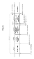
- FIG. 8A, 8B, and 8C illustrates an example display used for notifying a user of the disk type, the free capacity, and whether or not finalization is performed.
- FIG. 9A, 9B, and 9C illustrates an example display used for notifying the user of the disk type, the free capacity, and whether or not the finalization is performed.
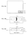
- FIG. 10A, 10B, and 10C illustrates an example display used for notifying the user of the disk type, the free capacity, and whether or not the finalization is performed.
- Fig. 11 is a flowchart illustrating medium-information-notification processing performed by the DVD-digital video camera shown in Fig. 1.
- Fig. 12 is a flowchart illustrating processing performed at step S2 shown in Fig. 11.
- Fig. 13 illustrates a disk-type-determination table used at step S30 shown in Fig. 12.
- Fig. 14 is a flowchart illustrating a disk-type-determination-processing task performed on the DVD-drive-2-side and a graphic-display-processing task performed on the information-processing-unit-1 side.
- the apparatus and the method of the present invention are applied for a digital video camera using a DVD, as a recording medium (DVD-digital-video camera).
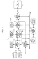
- Fig. 1 is a block diagram provided for illustrating the DVD-digital-video camera of this embodiment.
- the DVD-digital-video camera of the embodiment includes an information-processing unit 1 and a DVD drive 2 that are provided in one and the same cabinet.
- the configuration and operations of the information-processing unit 1 and those of the DVD drive 2 will be described separately.
- the information-processing unit 1 having the function of a host apparatus will be described.
- the information-processing unit 1 includes a camera unit 11, a color LCD (Liquid Crystal Display) 12, a video/audio interface unit (hereinafter referred to as a video/audio I/F unit) 13, a compression/expansion-signal processing unit 14, a data-control unit 15, a drive-control unit 16, an external-appliance interface unit (hereinafter referred to as an external-appliance I/F) 17, a system-control unit 18, a program memory 19, and a user-interface unit (hereinafter referred to as a user I/F unit) 20.
- the video/audio I/F unit 13, the compression/expansion-signal processing unit 14, and the data-control unit 15 include a screen memory 13M, a compression/expansion memory 14M, and a data memory 15M, respectively, where the memories are mainly used, as work areas.
- the system-control unit 18 is configured to control each of the units of the DVD-digital-video camera of the embodiment and includes, though not shown, a CPU (Central Processing Unit), a RAM (Random Access Memory) used as a work area, an EEPROM (Electrically Erasable and Programmable ROM) configured to store and hold setting parameters and various types of data that should be held even though the power is shut down, and a nonvolatile memory such as a flash memory.
- a CPU Central Processing Unit
- RAM Random Access Memory
- EEPROM Electrically Erasable and Programmable ROM
- the program memory 19 and the user I/F 20 are connected to the system-control unit 18.
- the program memory 19 stores various programs executed by the system-control unit 18 and data required for processing.
- the DVD drive 2 of the DVD-digital-video camera of the embodiment can use either of two laser lights with different wavelengths, namely, a red laser light and a blue laser light, as required.
- the program memory 19 includes file systems configured to perform the file management corresponding to each of different DVDs in which data is stored by using the laser lights with different wavelengths.
- a UDF-bridge file system in a DVD-video format and a UDF file system in a DVD-video recording format that are used for a red laser and a UDF-file system in a DVD-blue-video format and a UDF file system in a DVD-blue-video-recording format that are used for a blue laser are incorporated into the program memory 19.
- the user I/F 20 has a plurality of function keys, button switches, and slide keys, receives various instructions to start photographing, stop photographing, start reproduction, stop reproduction, and so forth that are transmitted from a user, and notifies the system-control unit 18 of the instructions. Subsequently, the system-control unit 18 controls each of the units according to the instruction transmitted from the user, so as to perform the processing corresponding to the instruction of the user.
- the camera unit 11 and the color LCD 12 are connected to the video/audio I/F unit 13, as shown in Fig. 1.
- the camera unit 11 includes a lens, a CCD (Charge Coupled Device), and so forth, converts the image of a subject transmitted through the lens into an analog-video signal by using the CCD, and transmits the analog-video signal to a circuit unit in a subsequent stage.
- a microphone is provided near the camera unit 11 so that speech is collected during photographing is performed. The collected speech is converted into an electric signal and captured.
- the LCD 12 is configured to display an image captured by the camera unit 11 and/or a reproduced image generated from video data read from a DVD inserted into the DVD drive 2 in color. Further, for example, a speaker is provided near the color LCD 12, though not shown, so that the speech collected by the microphone and/or reproduced speech generated from speech data read from the DVD inserted into the DVD drive 2 comes out.
- the video/audio I/F unit 13 Upon receiving the analog-video signal transmitted from the camera unit 11 and an analog-speech signal transmitted from the microphone, the video/audio I/F unit 13 converts these signals into digital signals in a format that can be processed by itself and transmits the converted video data and speech data to the compression/expansion-signal processing unit 14 in a subsequent stage. Thus, the video/audio I/F unit 13 can capture video and speech transmitted from the camera unit 11 or the like.
- the video/audio I/F unit 13 converts video data and speech data that are expanded and transmitted from the compression/expansion-signal processing unit 14 into analog signals, transmits the analog-video signal to the color LCD 12 and transmits the analog-speech signal to the speaker.
- the video/audio I/F unit 13 can externally transmit video and speech from itself.
- the compression/expansion-signal processing unit 14 compresses the video data and speech data transmitted from the video/audio I/F 13 according to a predetermined method and transmits the compressed video data and speech data to the data-control unit 15 in a subsequent stage. Further, the compression/expansion-signal processing unit 14 expands the compressed video data and speech data that are transmitted from the data-control unit 15, and transmits the expanded video data and speech data to the video/audio I/F unit 13.
- the data-compression method used by the compression/expansion-signal processing unit 14 may be, in the case of a still image, JPEG (Joint Photographic Experts Group), MPEG (Moving Picture Experts Group), and a method whose function is an extension of that of JPEG and/or MPEG, where the method shall be used in future, as a replacement for JPEG and/or MPEG.
- data-compression method may be, for example, MPEG2 and a method whose function is an extension of that of MPEG2, where the method shall be used in future, as a replacement for MPEG2.
- the JPEG 2000 system currently studied by the standardization association CIPA may be used, as a still-image compression method.
- MPEG4-AVC a compression system referred to as MPEG4-AVC
- HD hard disk
- the data-control unit 15 performs time-base correction for video data and/or speech data between an asynchronous DVD-digital-video camera and a DVD inserted into the DVD-digital-video camera by using the data memory 15M including an SDRAM (Synchronous Dynamic RAM) or the like, as a buffer memory.
- SDRAM Synchronous Dynamic RAM
- the data transmitted from the compression/expansion-signal processing unit 14 is stored in the data memory 15M via the data-control unit 15 and data that had been stored in the data memory 15M is read by the data-control unit 15, transmitted to the drive-control unit 16, and stored in the DVD inserted into the DVD drive 2, as will be described later.
- the video data and/or speech data that is supplied via the drive-control unit 16 and read from the DVD inserted into the DVD drive 2 is stored in the data memory 15M via the data-control unit 15.
- the data that had already been stored in the data memory 15M is read by the data-control unit 15, transmitted to the compression/expansion-signal processing unit 14, subjected to the data expansion and the digital/analog conversion, as described above, and externally transmitted.
- the data memory 15M is used in a so-called First-In-First-Out system.
- video data and/or speech data that is continuous with respect to time and transmitted from the camera unit 11 can be recorded onto the DVD inserted into the DVD drive 2 without interruption.
- video data and/or speech data that is continuous with respect to time and recorded onto the DVD inserted into the DVD drive 2 can be reproduced without interruption.
- the drive-control unit 16 is formed, as a connection interface between the information-processing unit 1 and the DVD drive 2.
- the drive-control unit 16 is formed, for example, as an ATAPI interface having a so-called Mt. Fuji multimedia command set which is installed thereon, where the Mt. Fuji multimedia command set is an optical-disk-drive command standard.
- the data transmitted from the data-control unit 15 is transmitted to the DVD drive 2 via the drive-control unit 16 and recorded onto the DVD inserted into the DVD drive 2. Further, the data read from the DVD inserted into the DVD drive 2 is transmitted to the data-control unit 15 via the drive-control unit 16, so as to be reproduced via the data-control unit 15, the compression/expansion-signal processing unit 14, and the video/audio I/F unit, as described above.
- the DVD-digital video camera of the embodiment includes the external-appliance I/F unit 17.
- the external-appliance I/F unit allows, for example, connecting the DVD-digital video camera to an external appliance such as a personal computer and is formed, as a USB (Universal Serial Bus) circuit, for example.
- USB Universal Serial Bus
- data can be transmitted and received via the data-control unit 15 and the drive-control unit 16, or the drive-control unit 16.
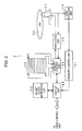
- Fig. 2 is a block diagram illustrating the DVD drive 2 installed on the DVD-digital video camera of the embodiment.
- the DVD drive 2 includes a firmware-control unit 21, a host interface unit (hereinafter referred to as a host I/F unit) 22, a packet-device-information unit 23, a memory-control unit 24, a drive-cache memory 25, a write/read unit 26, an optical-head unit (OPD: Optical Pickup Device) 27, and a disk-detection unit 28.
- a DVD 30 denotes an optical recording medium (DVD) inserted into the DVD drive 2.
- DVD optical recording medium
- the host I/F unit 22 is connected to the drive-control unit 16 of the information-processing unit 1 functioning as the host apparatus via the ATAPI interface so that data can be transmitted and received between the DVD drive 2 and the information-processing unit 1.
- the packet-device-information unit 23 performs packet transfer for data such as the command corresponding to the above-described Mt. Fuji command set between itself and the information-processing unit 1 by asynchronous hand shaking via the host I/F unit 22.
- the memory-control unit 24 uses the drive-cache memory 25, as a buffer memory, so as to transmit the data to the write/read unit 26 without interruption.
- the write/read unit 26 adds a CRC (Cyclic Redundancy Check) error-correction code and performs modulation processing, thereby generating a signal to be recorded. Then, the write/read unit 26 transmits the generated signal to be recorded to the optical-head unit 27.
- the optical-head unit 27 irradiates the inserted DVD 30 with the laser light for recording corresponding to the signal to be recorded transmitted from the write/read unit 26, so as to record the signal to be recorded onto the DVD 30.
- the optical-head unit 27 irradiates the DVD 30 with a laser light used for reading, receives a light reflected therefrom, and converts the reflected light into an electrical signal.
- the electrical signal is transmitted to the write/read unit 26.
- the write/read unit 26 performs demodulation processing, decoding processing for the CRC-error-correction code, error correction, and so forth, for the electrical signal transmitted from the optical-head unit 27.
- the write/read unit 26 transmits the demodulated data to the host-I/F unit 22 via the memory-control unit 24.
- the demodulated data is transmitted to the information-processing unit 1 via the host I/F unit 22.
- the DVD drive 2 includes the disk-detection unit 28 configured to read information such as the type of a disk by reading the discrimination information of an inserted DVD, where the DVD is inserted, upon receiving the signal obtained by converting the reflected light of the laser light applied from the optical-head unit 27 into the electrical signal.
- the disk-detection unit 28 configured to read information such as the type of a disk by reading the discrimination information of an inserted DVD, where the DVD is inserted, upon receiving the signal obtained by converting the reflected light of the laser light applied from the optical-head unit 27 into the electrical signal.
- the DVD drive 2 further includes the firmware-control unit 21 configured to determine the type of a DVD upon receiving a detection result transmitted from the disk-detection unit 28.
- the determination result obtained by the firmware-control unit 21 is transmitted to the information-processing unit 1 functioning, as the host apparatus by a handshake protocol, via the host-I/F unit 22.
- the firmware-control unit 21 also functions, as a system controller configured to control each of the units of the DVD drive.
- the optical-head unit 27 can use either of two laser lights with different wavelengths, namely, a known red laser light (with a wavelength of 650 nm, for example) and a blue laser light (with a wavelength of 405 nm, for example), according to the inserted DVD, as described above.
- information about a DVD such as the type of a DVD inserted into the DVD drive 2 is displayed on a display screen of the color LCD 12 via the video/audio I/F unit 13 controlled by the system-control unit 18 of the information-processing unit 1 so that the DVD information is transmitted to a user of the DVD-digital video camera, as described later.
- the DVD that can be inserted into the DVD drive 2 of the DVD-digital video camera of the embodiment for use may be a DVD-ROM, a DVD-R, and a DVD-RW.
- Each of the DVD-ROM, the DVD-R, and the DVD-RW includes a known DVD into which data is written by using a red laser light and a DVD-Blue into which data is written by using a blue laser light.
- the disk-discrimination information of each of the DVDs is recorded onto a reflection layer of the disk. Further, there are DVDs whose disk-discrimination information is recorded by burst cutting, which can be used for the embodiment.
- the DVD medium which can be used for the DVD-digital video camera of the embodiment includes, (1) a red-laser DVD-ROM, (2) a red-laser DVD-R, (3) a red-laser DVD-RW, (4) a DVD that is a red-laser medium and that uses burst cutting for medium-discrimination information, (5) a blue-laser DVD-ROM, (6) a blue-laser DVD-R, (7) a blue-laser DVD-RW, and (8) a DVD that is a blue-laser medium and that uses burst cutting for medium-discrimination information.
- the disk-detection unit 28 and the firmware-control unit 21 of the DVD drive 2 function, so as to determine to which type (kind) of the above-described DVDs (1) to (8) the inserted DVD corresponds and how much the free space of the DVD is. Further, where data is recorded onto the DVD in a DVD-video format, it is detected whether or not finalization is performed, and the user is notified of the detected information about the recording medium via the color LCD 12 with high viewability.
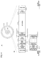
- Fig. 3 is provided for illustrating the physical format of the DVD-ROM.
- a DVD-ROM 100 has a center hall H at the center thereof, so as to be fixed to a spindle motor of a reproduction device, and a read area 101, a data area DT, and an end area 109 in that order from the inner-periphery side.
- the data area DT includes a management-data area 102, a read-in area 103, a VOL (volume) -information area 104, a File-Sys (file system)-information area 105, a VMG (Video Manager)-information area 106, a VTS (Video Title Set) areas 107(1), 107(2), ..., a read-out area 108, and the end area 109 in that order from the inner-periphery side, as shown in Fig. 3(B).
- the VMG-information area 106 includes a VMGI (Video Manager Information) area, a menu VOBS (Video Object Set) area, and a Bup (Backup) VMGI area, as shown in Fig. 3(B). Further, the VTS areas 107(1), 107(2), ... are portions on which video information and speech information are recorded. Each of the VTS areas 107(1), 107(2), ... has an identification number and is independently managed.
- each of the VTS areas 107(1), 107(2), ... has, for example, the video information and speech information of a single product such as a movie or a broadcast program that the producer of the product wishes to present to audiences. Otherwise, where the single product is divided into a plurality of parts, each of the VTS areas 107(1), 107(2), ... includes information of a single title, that is, a single group of the video information and speech information of each of the parts.
- information about a medium such as a type-discrimination code indicating the medium type is stored in the read area 101 provided at the inner-most-periphery side of the DVD-ROM 100 and discrimination information used for discriminating the disk from other disks and other required information are stored in the management-data area 102.
- the read-in area 103 stores information that is read at the time where the information is reproduced, such as information about the position where the stored information starts and the volume-information area 104 stores information that is used for discriminating the entire information stored in the DVD-ROM 100.
- the file-system area 105 stores information indicating the file configuration of data in the VMG-information area 106 and the VTS areas 107 (1), 107(2), ....
- the VMG-information area 106 stores, for example, a management table used for managing the entire information stored in the VMGI area, a menu showing the name of each title, an access table for accessing each of the titles (VTS), and backup information of the above-described information.
- the read-out area 108 on the outermost-periphery side stores termination information that is read at the time where reproduction of the stored information is terminated.
- LSN logical sector number
- PSN physical sector number
- the DVD-ROM As has been described, where the DVD-ROM is used, it becomes possible to discriminate between the red-laser DVD-ROM and the blue-laser DVD-ROM based on the type-discrimination code of the read area 101 on the innermost-periphery side. Further, it becomes possible to discriminate between the DVD-ROM and the other disks based on the level of light reflected from the management-data area 102.
- Fig. 4 is provided for illustrating the physical format of the DVD-R.
- a DVD-R 200 has a center hall H at the center thereof, so as to be fixed to a spindle motor of a reproducer and/or a recorder, and has a read area 201, a recordable area DD, and an end area 208 in that order from the inner-periphery side.
- the recordable area DD has a light-intensity-test area 202, a management-data area 203, a read-in area 204, a file-system-information area 205, a data area 206, a read-out area 207, and the end area 208 that are provided in that order from the inner-periphery side, as shown in Fig. 4(B).
- the read area 201 also stores information about the medium, such as a type-discrimination code indicating the medium type.
- the light-intensity-test area 202 stores test information, where a test for setting the intensity of laser light (laser light) used for recording is conducted.
- the management-data area 203 stores data on the intensity of the set laser light and information that becomes required, so as to be held during the recording process.
- the read-in area 204 stores, for example, start information that is read at the time where reproduction of the record information recorded onto the DVD-R 200 is started during information is recorded.
- the file-system-information area 205 stores information indicating the file configuration of the record information.
- the data area 206 stores actual record information including image data, speech data, and so forth.
- the read-out area 207 stores termination information that is read at the time where reproduction of recorded information is terminated during record information including image data, speech data, and so forth is recorded.
- LSN logical sector number
- PSN physical sector number
- the disk is a DVD-R according to the discrimination information stored in the discrimination-information area 2031 of the management-data area 203, and discriminate between a DVD-ROM and other disks based on the level of light reflected from the management-data area 203.
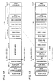
- Figs. 5A and 5B illustrate the case where video data and speech data are stored in the DVD-video format in the DVD-R.
- Fig. 5A shows the state where the finalization is not yet performed and
- Fig. 5B shows the state after the finalization is performed.
- a reserved area 205a which is an unrecorded area adapted to store information including volume information, file-system information, VMG information, and so forth is provided in advance by the finalization.
- the read area 201, the light-intensity-test area 202, the management-data area 203, and the read-in area 204 are provided on the inner-periphery side with respect to the reserved area 205a, where the areas cannot be directly read by the information-processing unit 1 and can be used only by a firmware of the DVD drive 2.
- the data area 206 stores VTS#1, VTS#2, ..., namely, groups of video data and speech data for each title, as is the case with the DVD-ROM 100 that is described above with reference to Fig. 3, and necessary information is stored in the management-data area 203, the read-in area 204, and the read-out area 207.
- volume information, file-system information, VMGI, a menu VOBS, and backup VMGI that are information stored in the reserved area 205a are generated in the DVD drive 2 based on the VTS#1, the VTS#2, ..., that is, the data stored in the data area 206.
- the above-described information is stored in the reserved area 205a of the DVD-R.
- the volume information, the file-system information, and the VMG information including the VMGI, the menu VOBS, and the backup VMGI are stored in an area between the read-in area and the data area, as is the case with the physical format of the DVD-ROM shown in Fig. 3, so that the DVD can be reproduced by a DVD-ROM drive other than the recorder that was used for the recording, as a DVD-ROM-compatible disk.
- Fig. 4 it becomes possible to determine whether or not the finalization is performed according to whether or not data is stored in the reserved area 205a provided between the read-in area 204 and the data area 206. In that case, there is no need to confirm all of the volume information, the file-system information, the VMGI, the menu VOBS, and the backup VMGI that should be stored in the reserved area 205a. For example, it is possible to determine whether or not the finalization was performed by detecting whether or not the file-system information and/or the VMGI information exist.
- Temp VMGI provisional VMGI
- provisional VMGI information used for generating information such as the VMG information that is generated during the finalization is generated based on record information during the information is recorded, so as to perform the finalization correctly in a short time period, for example.
- the generated Temp VMGI may be stored in the data area.
- the type of disk or the like can also be determined in the above-described manner.
- Fig. 6 is provided for illustrating the physical configuration of a read-in area of the DVD-RW.
- the external view and physical format of the DVD-RW are roughly the same as those of the DVD-R shown in Fig. 4.
- the DVD-RW also has the read area 201, the light-intensity-test area 202, the management-data area 203, the read-in area 204, the file-system-information area 205, the data area 206, the read-out area 207, and the end area 208 that are provided on the disk in that order from the inner-periphery side toward the outer-periphery side.
- the read-in area 204 has an initial zone 301, a system-reserved area 302, an RW-physical-format-information area 303, a reference zone and a buffer zone 304, and a control-data area 305 in which an emboss bit is stored, as shown in Fig. 6.
- the RW-physical-format-information area 303 stores, for example, various information about the type of a DVD standard (DVD-ROM, DVD-RAM, DVD-RW, and so forth) to be used, the part version, the disk size, the maximum read rate, the disk structure (a single-layer ROM/RAM disk and a double-layer ROM/RAM disk), the recording density, the read power, the peak power, the bias power, and the medium manufacturing.
- DVD-ROM, DVD-RAM, DVD-RW, and so forth the part version
- the disk size the maximum read rate
- the disk structure a single-layer ROM/RAM disk and a double-layer ROM/RAM disk
- the recording density the read power
- the peak power the bias power
- the medium manufacturing for example, various information about the type of a DVD standard (DVD-ROM, DVD-RAM, DVD-RW, and so forth) to be used, the part version, the disk size, the maximum read rate, the disk structure (a single-layer ROM/RAM disk and a double-layer
- the physical-format information including the DVD-standard type (book type), the number of layers of the disk, and so forth and various information about the medium manufacturing are emboss-recorded in the control-data area.
- a DVD 400 having the burst-cutting area can be used for any one of a DVD-ROM, a DVD-R, and a DVD-RW.
- Figs. 7A and 7B are provided for illustrating the DVD 400 including the burst-cutting area.
- the DVD 400 having the burst-cutting area has a burst-cutting area 401 in the innermost-periphery part of the disk.
- read-in areas a reproduce-only area 402 and a record-only area 403
- a user-data area 404 and a read-out area 405 are provided outside the burst-cutting area 401.
- a reflection layer of the DVD 400 is irradiated with pulse-like high-power laser lights via a focus lens so that part of the reflection layer, the part being irradiated with the high-power laser lights, is removed. Subsequently, stripe-like data subjected to Phase encoding modulation is stored in the burst-cutting area, for example.
- the burst-cutting area is irradiated with a laser light used for reading. Since the amount of reflected light at the part from which the reflection layer is removed reduces, the fluctuation of the reflected-light amount is detected and binarized. Subsequently, Phase encoding modulation is performed so that the data can be read.
- the type-discrimination code used for identifying the disk type or the like is stored in the burst-cutting area by the burst cutting so that the data in the burst-cutting area is read. Subsequently, it becomes possible to obtain the type-discrimination code, determine the type of the disk, namely, to which of the DVD-ROM, the DVD-R, and the DVD-RW does the disk corresponds, and determine whether the disk is for a red laser or a blue laser.
- data indicated by specifiers DATA0, DATA1, ... is stored in the burst-cutting area 401 by synchronization codes indicated by specifiers SY. Further, an error-detection code indicated by the specifier EDC and an error-correction code indicated by the specifier PARITY0 are added and recorded, so as to maintain the read rate at a suitable level.
- the DVD drive 2 can detect the recorded capacity by tracking the recorded data and/or based on predetermined record information of an inserted DVD disk, for example. Further, the total storage capacity of the inserted DVD can be correctly determined based on information stored in a predetermined area of the DVD. Therefore, the free capacity of the inserted disk can be calculated by subtracting the recorded capacity obtained in the above-described manner from the total storage capacity. Subsequently, it becomes possible to notify the user of the free capacity via the color LCD 12 or the like.
- either a red laser or a blue laser can be used, as the laser-light source. Therefore, the user is clearly informed that whether a DVD to be used is for the red laser or the blue laser.
- the DVD-digital video camera of the embodiment has the color LCD 12 including color filters of three primary colors including red (R), green (G), and blue (B), and illuminators of three primary colors including red (R), green (G), and blue (B). Therefore, the DVD-digital video camera can represent a long-wavelength region (wavelength: 600 nm to 780 nm, a red light with an orange tint, a red tint, and so forth), a medium-wavelength region (wavelength: 500 nm to 600 nm, a green light with a green tint, a yellow tint, and so forth), and a short-wavelength region (wavelength: 380 nm to 500 nm, a blue light with a violet tint, an indigo-blue tint, a blue tint, and so forth).
- a long-wavelength region wavelength: 600 nm to 780 nm, a red light with an orange tint, a red tint, and so forth
- a medium-wavelength region wavelength: 500
- the notification is performed by displaying the color of the red light in the long-wavelength region.
- the notification is performed by displaying the color of the blue light in the short-wavelength region. That is to say, instead of simply displaying the red color or the blue color, the color of the long-wavelength region and/or that of the short-wavelength region is displayed. Subsequently, it becomes possible for the user to visually determine whether the DVD inserted into the DVD-digital video camera of the embodiment is for the red laser or the blue laser with speed and precision.
- the user can effortlessly and correctly identify not only the type of laser light to be used, but also the free-capacity display and whether or not the finalization was performed without thinking through as simple a display image as possible.
- Figs. 8A and 8B, and Figs. 8C to 10A, and Figs. 10B and 10C are provided for illustrating example display images of the disk types, the free capacities, and whether or not the finalization is performed.
- a medium-information-display area G is provided, for example, at an upper-right part of the color LCD 12 so that a capacity display G1 in the form of a circle graph showing the recorded capacity and free capacity of a DVD to be used, a finalization-finished display G2, a recordable-time display G3, and a non-finalization display G4 are displayed in the medium-information-display area G.
- the recorded-capacity display G11R corresponding to the recorded capacity is indicated in a dark red color and the free-capacity display G12R corresponding to the free capacity is indicated in a light red color. Further, by displaying the recordable-time display G3 according to the free capacity, the user is clearly informed that how much data can further be recorded.
- the DVD to be used is a DVD-R
- the non-finalization display G4 is displayed on the left side of the capacity display G1, as shown in Fig. 8C, which informs the user that the finalization has not yet been performed.
- the capacity display G1 and the recordable-time display G3 are displayed, as shown in Fig. 8B.
- a time period during which the recordable time is displayed for example, a value obtained by roughly calculating a remaining recordable time, shown as (remaining data amount ⁇ average bit rate in a selected compression mode), can be used.
- the capacity display G1 is presented, as play-chapter display including the played-capacity display and remaining-play capacity, and the recordable-time display G3 is presented, as remaining-play-time display.
- the recording-capacity display G11R and the free-capacity display G12R are presented, as values obtained by rounding values that are obtained, shown as (recorded capacity ⁇ total storage capacity) and (free capacity ⁇ total storage capacity), by 10%.
- the blue-laser DVD except that the color used for the recorded-capacity display and the free-capacity display is blue in place of red. That is to say, where the DVD to be used is the blue-laser DVD-RW, the part corresponding to a recorded-capacity-display G11B of the capacity display G1 in the form of the circle graph is represented in dark blue and the part corresponding to a free-capacity display G12B is represented in light blue, as shown in Fig. 9A. Further, the recordable-time display G3 is also displayed.
- the finalization-finished display G2 is displayed in addition to the capacity display G1 in the circle-graph form and the recordable-time display G3, as shown in Fig. 9B.
- the non-finalization display G4 is displayed in addition to the capacity display G1 in the circle-graph form and the recordable-time display G3, as shown in Fig. 9C.
- the play-chapter display including the played-capacity display and the remaining-play capacity is presented in blue color, as the capacity display G1. Further, the recordable-time display G3 is displayed, as the remaining-play-time display.
- the capacity display G1 may be displayed without being limited thereto.
- the capacity display may be presented in the form of a bar graph, as shown in Figs. 10A, 10B, and 10C.
- a medium-information-notification area GG is provided at an lower-right part of a display screen of the color LCD 12 so that a capacity display GG1 and a recordable-time display GG2 are displayed therein, as shown in Fig. 10A.
- the capacity display GG1 includes a recorded-capacity display GG1 and a free-capacity display GG12, as shown in Figs. 10B and 10C.
- the part corresponding to the recorded-capacity display GG1 is displayed in a dark-red color and the part corresponding to the free-capacity display GG12 is displayed in a light-red color.
- the blue-laser DVD is used, the part corresponding to the recorded-capacity display GG1 is displayed in a dark-blue color and the part corresponding to the free-capacity display GG12 is displayed in a light-blue color.
- a finalization-finished display GG3 is displayed, as shown in Fig. 10B.
- a non-finalization display GG4 is displayed, as shown in Fig. 10C.
- Figs. 10A, 10B, and 10C the user is informed of information about the medium, as is the case with Figs. 8A, 8B, and 8C, and Figs. 9A, 9B, and 9C except that the capacity-display part is presented, as the bar graph in place of the circle graph.
- the recorded-area display is presented in dark red and/or dark blue and the free-area display is presented in light red and/or light blue on the grounds that where the free-area display is represented in monochrome, for example, and where the DVD has not yet been used, the user cannot be informed whether the DVD is for a red laser or a blue laser. Therefore, the light red and the light blue have predetermined darkness so that the user can determine them to be red and blue.
- part of each of the capacity display G1 and the capacity display GG1 that are shown in Figs. 8A, 8B, and 8C, and Figs. 9A, 9B, and 9C, such as the center part thereof may be color-coded according to whether the DVD is for the red laser or the blue laser, or according to whether a DVD using the background of the medium-information notification area is for the red laser or the blue laser.
- red-laser DVD characters “Red”, “a kanji representing red”, “R”, and so forth are displayed
- blue-laser DVD characters “Blue”, “a kanji representing blue”, “B”, and so forth are displayed, as notification for the user.
- color display may be presented at any part of the color LCD 12 according to whether the DVD to be used is for the red laser or the blue laser.
- a rim part of the display area of the color LCD 12 may be rimmed according to whether the DVD to be used is for the red laser or the blue laser.
- the DVD to be used is the red-laser DVD
- the long-wavelength region (wavelength: 600 nm to 780 nm, a red light with an orange tint, a red tint, and so forth) is used.
- the short-wavelength region (wavelength: 380 nm to 500 nm, a blue light with a violet tint, an indigo-blue tint, a blue tint, and so forth) is used. That is to say, a color by which the user can determine whether the DVD to be used is for the red laser or the blue laser at a glance is used.
- the medium-information-display area can be provided at a predetermined position on the display screen of the color LCD 12 without being limited to the above-described embodiment.
- the display images of the capacity displays G1 and GG1, and the recordable-time displays G3 and GG2 are displayed or not according to the user. That is to say, the user can display the capacity displays G1 and GG1, and the recordable-time displays G3 and GG2, as required.
- the DVD-digital video camera of the embodiment determines to which of the DVD-ROM, the DVD-R, and the DVD-RW does the DVD inserted therein corresponds and determines whether the DVD is for a red laser or a blue laser with speed and precision. Further, the DVD-digital video camera determines the free capacity and whether or not the finalization is performed with precision, so as to plainly inform the user of the above-described information.
- FIG. 11 is provided for illustrating medium-information notification that is performed, where a DVD is inserted into the DVD-digital video camera of the embodiment.
- the information-processing unit 1 and the DVD drive 2 are connected to each other via an ATAPI interface having the Mt. Fuji-multimedia command set mounted thereon. Therefore, where the DVD is inserted, the drive-control unit 16 of the information-processing unit 1 generates the Test Unit Ready (00h) command and determines whether or not a medium is chucked into the drive by Request Sense and rotation of the spindle motor is started.
- Test Unit Ready 00h
- the system-control unit 18 of the information-processing unit 1 switches the processing mode based on the result of the disk-type determination performed at step S2 by the DVD drive 2 (step S3).
- the packet-device-information unit 23 generates a packet-command-response data page based on the determination result and transmits the data page back to the system-control unit 18 of the information-processing unit 1 via the host-I/F unit 22.
- the packet-device-information unit 23 generates the response data page according to a Table 297-READ DVD STRUCTURE Data Format defined by the above-described Mt. Fuji-multimedia command set, for example. Therefore, the system-control unit 18 of the information-processing unit 1 refers to the generated data page via the drive-control unit 16.
- Fuji-multimedia command set via the drive-control unit 16, where the format is held in the packet-device-information unit 23, reads Book Type that is a field of a first byte string of response data of the DVD read-in structure starting from the fifth byte on the beginning side, and obtains the result of medium-type determination performed for the DVD disk.
- the book type value 0000b (hereinafter, b denotes binary numbers) denotes a DVD-ROM
- the value 0001b denotes a DVD-RAM
- the value 0010b denotes a DVD-R
- the value 0011b denotes a DVD-RW
- the value 1001b denotes a DVD + RW.
- a single value of Reserved of the Others type indicates a DVD blue disk, so that not only the red-laser disk, but also the blue-laser disk can be handled.
- the system-control unit 18 of the information-processing unit 1 obtains the total disk capacity from the DVD drive 2, as the sector number, via an API (Application Program Interface) of a UDF bridge file system in the DVD-video format (DVF) (step S4).
- API Application Program Interface
- the system-control unit 18 of the information-processing unit 1 obtains the total disk-capacity information, the free-capacity information (remaining recordable-capacity information) from the DVD drive 2 via the API of the UDF bridge file system in the DVD-video format (DVF), and information about whether or not the finalization is performed (step S6).
- step S6 the remaining amount is displayed, as the total remaining amount by the graphic display of the red-wavelength region, and the finalization-finished display and/or the non-finalization display is performed (step S7), as has been described with reference to Figs. 8A, 8B, and 8C, and Figs. 10A, 10B, and 10C.
- the system-control unit 18 of the information-processing unit 1 obtains the total disk-capacity information and the free-capacity information (remaining recordable-capacity information) from the DVD drive 2 via the API of the UDF bridge file system in the DVD-video recording format (DVRF) (step S8).
- the DVD-RW is used, editing or the like is often performed, since the DVD-RW is rewritable. Therefore, according to this embodiment, where the DVD-RW is determined to be a red-laser DVD-RW, the recording format thereof is determined to be the DVD-video recording format.
- step S8 the remaining amount is displayed, as the total remaining amount by the graphic display of the red-wavelength region (step S9), as has been described with reference to Figs. 8A, 8B, and 8C, and Figs. 10A, 10B, and 10C.
- the DVD-video format is used, as the record format, so as to secure DVD-ROM downward compatibility, and the finalization is performed.
- step S3 by determining the recording-format type based on information recorded onto the inserted disk, at step S3, it is determined whether the data is recorded in the DVD-video format or the DVD-video recording format by the processing performed at step S8 by the information-processing unit 1.
- step S8 information about whether or not the finalization is performed is obtained, at step S8, and the information about the disk is displayed, at step S9, as shown in Figs. 8A and 8C, and Figs. 10B and 10C. Further, the finalization-finished display or the non-finalization display may be performed.
- the system-control unit 18 of the information-processing unit 1 obtains the total disk capacity from the DVD drive 2, as the sector number, via the API (Application Program Interface) of the UDF bridge file system in the DVD-video format (DVF) (step S10).
- the system-control unit 18 of the information-processing unit 1 obtains the total disk-capacity information and the free-capacity information (remaining recordable-capacity information) from the DVD drive 2 via the API of the UDF bridge file system in the DVD-video format (DVF), and information about whether or not the finalization is performed (step S12).
- step S6 the processing at step S6 is performed, as has been described with reference to Figs. 8A, 8B, and 8C, and Figs. 10A, 10B, and 10C
- the remaining amount is displayed, as the total remaining amount by the graphic display of the blue-wavelength region, and the finalization-finished display and/or the non-finalization display is performed (step S13).
- the system-control unit 18 of the information-processing unit 1 obtains the total disk-capacity information and the free-capacity information (remaining recordable-capacity information) from the DVD drive 2 via the API of the UDF bridge file system in the DVD-video recording format (DVRF) (step S14).
- the DVD-video format and the DVD-video recording format can be used, as is the case with the above-described disk determined to be the red-laser-capable DVD-RW medium.
- the DVD-RW is used, editing or the like is often performed, since the DVD-RW is rewritable. Therefore, according to this embodiment, where the DVD-RW is determined to be the blue-laser DVD-RW, the recording format thereof is determined to be the DVD-video recording format.
- step S15 the remaining amount is displayed, as the total remaining amount by the graphic display of the blue-wavelength region (step S15), as has been described with reference to Figs. 9A, 9B, and 9C, and Figs. 10A, 10B, and 10C.
- the DVD-video format is used, as the record format, so as to secure the DVD-ROM downward compatibility. Finally, the finalization is performed.
- step S3 by determining the recording-format type based on the information recorded onto the inserted disk, at step S3, it is determined whether the data is recorded in the DVD-video format or the DVD-video recording format through the processing performed at step S14 by the information-processing unit 1.
- step S14 information about whether or not the finalization is performed is obtained, at step S14, and the information about the disk is displayed, as shown in Figs. 9B and 9C, and Figs. 10B and 10C, at step S15. Further, the finalization-finished display or the non-finalization display may be performed.
- an AV-data file system designed specifically for a DVD-Blue-RAM disk that is customized for an MPEG-TS recorder of a BS-digital-broadcast receiver, where the AV-data-file system uses Play List in Clips can be used in place of the DVD-video recording format that is seamlessly connected to a PC and widely available. Further, it is possible to identify the AV-data file system and inform the user of the fact.
- steps S5, S7, S9, S11, S13, and S15 the processing shown in Fig. 11 is finished. Further, the information display at each of steps S5, S7, S9, S11, S13, and S15 can be automatically terminated after a predetermined time period, or terminated according to an instruction transmitted from the user.
- a red laser is emitted and the medium type is determined based on the result of a read discrimination code.
- a blue laser is emitted, it is possible to determine that the disk is an ROM due to the fact that a read-only disk has a high reflectivity.
- a read-only part on the read-in inner-periphery side of the medium may be formed, as an emboss-reflection layer, so as to increase the light reflectivity thereof. Subsequently, the medium type is determined according to the result of a read discrimination code.
- a management-data area of a recordable medium-reflection film part on the read-in periphery side may be read by a red laser, so that the medium type may be determined according to a read-signal-level detection signal.
- the medium is a ROM disk and the discrimination code does not indicate a red-laser disk, or where the reflection-signal level of the medium-reflection-film part indicates that data cannot be read by the red laser and the data can be read by switching to a blue laser, it is possible to determine that the ROM disk is the blue-laser disk.
- Fig. 12 is a flowchart illustrating the disk-type determination processing performed at step S2 shown in Fig. 11.
- the firmware-control unit 21 of the DVD drive 2 starts the disk-type determination processing shown in Fig. 12 based on the read data.
- the firmware-control unit 21 determines whether or not the inserted DVD is a DVD-ROM based on data read from the inserted DVD, namely, data read from the read area, the management-data area, the read-in area, or the burst-cutting area (step S21) and determines whether or not the DVD is a red-laser DVD (step S22), and determines whether or not the DVD is a DVD-RW (step S23).
- the inserted DVD is determined to be a DVD-ROM by the determination processing performed at step S21, data indicating that the determination result is "true” is stored in an area (determination result 1) adapted to store the determination result obtained at step S21 (step S24). Further, where the inserted DVD is not determined to be the DVD-ROM by the determination processing performed at step S21, data indicating that the determination result is "false” is stored in the area (determination result 1) adapted to store the determination result obtained at step S21 (step S25).
- the inserted DVD is determined to be a red-laser DVD by the determination processing performed at step S22
- data indicating that the determination result is "true” is stored in an area (determination result 2) adapted to store the determination result obtained at step S22 (step S26).
- data indicating that the determination result is "false” is stored in the area (determination result 2) adapted to store the determination result obtained at step S22 (step S27).
- the inserted DVD is determined to be a DVD-RW by the determination processing performed at step S23
- data indicating that the determination result is "false” is stored in an area (determination result 3) adapted to store the determination result obtained at step S23 (step S28).
- data indicating that the determination result is "false” is stored in the area (determination result 3) adapted to store the determination result obtained at step S23 (step S29).
- the determination result 1 (information about whether or not the DVD is the DVD-ROM), the determination result 2 (information about whether or not the DVD is the red-laser DVD), the determination result 2 (information about whether or not the DVD is the DVD-RW) are obtained and the disk type is determined based on the above-described three types of information (step S30). More specifically, the processing at step S30 is performed based on a disk-type-determination table shown in Fig. 13.
- the DVD is determined to be a red-laser DVD-ROM. In that case, processing is started from step S4 shown in Fig. 11. Further, where the determination result 1 indicates “false”, the determination result 2 indicates “true”, and the determination result 3 indicates "false", as shown in column (2), the DVD is neither the DVD-ROM nor the DVD-RW. Therefore, the DVD is determined to be the red-laser DVD-R. In that case, the processing is started from step S6 shown in Fig. 11.
- the DVD is determined to be a red-laser DVD-RW. In that case, the processing is started from step S8 shown in Fig. 11.
- the DVD is determined to be a blue-laser DVD-ROM. In that case, the processing is started from step S10 shown in Fig. 11. Further, where the determination result 1 indicates “false”, the determination result 2 indicates “false”, and the determination result 3 indicates "false", as shown in column (5), the DVD is neither the DVD-ROM nor the DVD-RW. Therefore, the DVD is determined to be the blue-laser DVD-R. In that case, the processing is started from step S12 shown in Fig. 11.
- the DVD is determined to be the blue-laser DVD-RW. In that case, the processing is started from step S14 shown in Fig. 11.
- step S2 shown in Fig. 11 a disk-type-determination-processing task on the DVD-drive 2's part
- step S3 on down a graphic-display-processing task on the information-processing unit 1's part
- the firmware-control unit 21 of the DVD drive 2 performs a series of processing shown in Fig. 14(A).
- the DVD drive 2 determines whether the inserted DVD is a DVD-ROM, a DVD-R, or a DVD-R (step S101), determines whether the inserted DVD is for a red laser (Red) or a blue laser (Blue) (step S102), determines whether or not a file system used for the inserted DVD is in the DVD-video format (step S103), and performs file-system selection and free-area detection (step S104).
- each of the bit patterns is a bit pattern used for inter-task transmission from a medium-type-determination-processing task to a graphic-display task and transmitted, as a message.
- the system-control unit 18 of the information-processing unit 1 performs capacity display such as remaining-amount display based on information transmitted from the DVD drive 2, as shown in Fig. 14(B) (step S201), controls a display color used for the capacity display (step S202), displays whether or not the finalization is performed (step S203), and displays time information about a recordable time, a remaining-play time, and so forth (step S204).
- the information-processing unit 1 and the DVD rive 2 operate in concert with each other, so as to clearly notify the user that whether the DVD to be used is the red-laser DVD or the blue-laser DVD, the free capacity of the DVD, and whether or not the finalization is performed.
- the DVD drive 2 performs the processing shown in Fig. 12 according to a request transmitted from the information-processing unit 1, obtains the determination results 1, 2, and 3, and determines the disk type according to the disk-type determination table shown in Fig. 13.
- the system-control unit 18 of the information-processing unit 1 obtains the determination result and switches the processing.
- the DVD drive 2 may perform the processing shown in Fig. 12 and obtain the determination results 1, 2, and 3. Then, the information-processing unit 1 may obtain the determination results and determine the disk type according to the disk-type-determination table shown in Fig. 13.
- DVD-digital video camera is described in the above-described embodiment, as an example, various types of recorders and recording/reproduction devices using various types of optical disks including a DVD, a CD, and so forth, as a recording medium, may be used, without being limited to the above-described embodiment.
- the present invention is used for a recorder or a recording/reproduction device that can use a plurality of optical disks in different dimensions, such as a 12-cm optical disk, an 8-cm optical disk, and a smaller disk, that is, optical disks with different storage capacities, it becomes possible to clearly notify the user of the determination information about whether the disk is a red-laser optical disk or a blue-laser optical disk and the free capacity, which reduces erroneous determination of the free capacity.
- the red laser light with the wavelength of 650 nm and the blue laser light with the wavelength of 405 nm are used.
- a laser light with a wavelength of more than 650 nm may be used, even though the laser light is classified as, for example, a so-called red laser light.
- a laser light with a wavelength of less than 405 nm may be used, even though the laser light is classified, as the blue laser light.
- the color corresponding to a wavelength region to which the wavelength of a laser-light source belongs is displayed for each optical disk so that the difference between laser lights used for writing and/or reading data is indicated. More specifically, for example, where an optical disk adapted to write/read data by using a violet laser light with a wavelength of 400 nm or less is used, where the violet laser light will be usable in future, the user may be informed of the disk type and the free capacity by displaying a color with the wavelength corresponding to the 380-nm-to-500-nm band.
- the above-described description applies to the case where a laser light in a medium-wavelength region is used, for example.
- the user may be informed of the disk type and the free capacity by displaying a color with a wavelength of 500 nm to 600 nm.
- the present invention allows clearly notifying a user what wavelength does the laser light of an optical-recording medium to be used have with good visibility.
- the present invention further allows clearly notifying the user of information about the optical-recording medium with good visibility, such as the free capacity of the optical-recording medium to be used, whether or not the finalization is performed, and so forth.
Landscapes
- Engineering & Computer Science (AREA)
- Multimedia (AREA)
- Computer Security & Cryptography (AREA)
- Signal Processing (AREA)
- Optical Recording Or Reproduction (AREA)
- Signal Processing For Digital Recording And Reproducing (AREA)
- Indexing, Searching, Synchronizing, And The Amount Of Synchronization Travel Of Record Carriers (AREA)
Abstract
To allow using laser lights with different wavelengths,
as required, according to an optical-recording medium to be
used and notifying a user of various information about the
optical-recording medium which is inserted.
A DVD drive 2 reads various information items that
include a read-in area of an inserted DVD and that are
provided on the inner-periphery side with respect to the
read-in area, and it is determined whether the inserted DVD
is for red data or a blue laser based on the information
items. According to the determination result and the
detection result, a system-control unit 18 of an
information-processing unit 1 controls a video/audio-I/F
unit 13 so that the determination result is displayed on an
LCD 12. Where the inserted DVD is a red-laser DVD, the
determination result is displayed by the color display
corresponding to a red-wavelength region, and where the
inserted DVD is a blue-laser DVD, the determination result
is displayed by the color display corresponding to a blue-wavelength
region.
Description
The present invention relates to an apparatus and a
method that allows notifying a user of information about an
optical-recording medium such as a DVD (Digital Versatile
Disk), where the optical-recording medium is used.
DVD-ROMs functioning as read-only optical disks are
used, as large-capacity optical-recording mediums. Further,
DVD-Rs (DVD-Recordable) functioning as write-once optical-recording
mediums, DVD-RWs (DVD ReWritable) functioning as
rewritable optical recording mediums, and so forth are
presented, as optical-recording mediums that can be
reproduced by a DVD-ROM drive (a DVD-ROM reproducer).
Further, there is a DVD Video Format functioning as a
record format that is used, where image data or the like is
recorded onto the above-described DVD-R and DVD-RW.
Further, a DVD Video Recording Format is presented, as a
record format that can be used, where image data or the like
is recorded onto the DVD-RW.
Here, the DVD-video format is inherently provided for
the DVD-ROM and adequate for additional-data recording.
Where image data and/or speech data is recorded onto the
DVD-R by using the DVD-video format, so-called finalization
processing is required, so as to use the DVD-R by a
reproducer different from a recorder. The finalization
processing is predetermined processing performed for
generating predetermined information referred to as so-called
VMG (Video Manager) information based on information
recorded onto the DVD-R and recording the VMG information
onto the DVD-R.
That is to say, the finalization processing denotes
processing performed for eventually making the DVD-R enter
the additional-recording prohibition state, where data is
additionally recorded onto the DVD-R in the DVD-video
format, and closing the DVD-R, as a DVD-ROM compatible disk
and a data disk that can be read by a DVD-ROM drive.
On the other hand, the DVD-video recording format has
editing flexibility and has a data structure allowing making
edits including scene deletion, scene addition, and so forth
with relative ease. The DVD-video recording format is
mainly used for the DVD-RW which is a rewritable disk-recording
medium. Further, the DVD-video recording format
does not require the finalization processing, even though
the finalization processing is required for the above-described
DVD-video format.
Thus, in addition to the DVD-ROM, the DVD-R capable of
additional recording and the rewritable DVD-RW that are
compatible with the DVD-ROM are widely used. Where image
data or the like is recorded onto the DVD-R and/or the DVD-RW,
it is required that a user be notified of the free
capacity of the DVD-R and/or the DVD-RW used for recording
with precision in view of the convenience of the user.
Japanese Unexamined Patent Application Publication No.
2001-351363 discloses a technology used for a video camera
that uses a CD-R (Compact Disc Recordable), as a recording
medium. Although the CD-R is not a DVD medium, it is the
same optical-recording medium as the DVD. The technology
allows displaying the free area of the CD-R and whether or
not the close-session processing corresponding to
finalization processing performed for the DVD-video format
is performed.
To the technology disclosed in Japanese Unexamined
Patent Application Publication No. 2001-351363 allows
knowing the capacity of an optical disk used for recording
and notifying the user of whether or not the close-session
processing is performed. Subsequently, the user can
correctly understand the free space and appropriately
determine whether or not the free capacity is adequate.
Further, the technology has an advantage so that processing
adapted to cancel the close-session processing can be
performed immediately, where data is further recorded onto
the optical disk subjected to the close-session processing.
Further, where image data or the like is recorded onto
an optical recording medium including the DVD or the like, a
red laser with a wavelength of 635 nm (nanometer), 650 nm
(nanometer), and so forth is generally used. However, in
the future, a blue laser with a short wavelength of 405 nm,
for example, may be used.
A blue-laser DVD onto which data is recorded by using
the blue laser with the wavelength of about 405 nm has a
recording surface density four times higher than that of a
red-laser DVD onto which data is recorded by using a
currently-used red laser. Namely, the blue-laser DVD has a
record density four times higher than that of the red-laser
DVD.
Further, for example, the light reflectivity, track
pitch, and so forth of the red-laser DVD are different from
those of the blue-laser DVD, so that either the red-laser
DVD or the blue-laser DVD needs to be used, as required.
However, considering the fact that the red laser is widely
used, the red-laser DVD and the blue-laser DVD should
coexist so that either the red-laser DVD or the blue-laser
DVD can be used, as required, according to intended use
and/or preferences.
Therefore, considering the convenience of the user, a
recorder and/or a reproducer that can switch between the red
laser and the blue laser for use according to the type of an
optical disk should be offered. In the above-described
recorder that has both a red-laser-light source and a blue-laser-light
source that are mounted thereon and that can use
the red-laser-light source and the blue-laser-light source
by switching therebetween, it is preferable that a laser
light used for recording be automatically selected according
to whether the DVD to be used is the red-laser DVD or the
blue-laser DVD.
In that case, as described above, the recording
capacity of the red-laser DVD is significantly different
from that of the blue-laser DVD. Subsequently, the user may
mistake the red-laser DVD for the blue-laser DVD, for
example, so that all of target information cannot be
recorded due to insufficient capacity.
Therefore, it is preferable that the user be notified
of information about whether or not the DVD to be used is
for a red laser or a blue laser and how much the free
capacity of the DVD to be used is. Further, it is
preferable that the user be capable of knowing the above-described
information with ease and precision.
Further, since the DVD-R is used only for additional
recording, image data and/or speech data is recorded in the
DVD-video format. If it is possible to notify the user of
information about whether or not the above-described
finalization processing is finished, the convenience of the
user increases.
Particularly, since a disk medium and a battery area
are often inserted into and/or extracted from a mobile video
camera that uses a DVD, as a recording medium, it is
preferable that the user be plainly notified of information
about whether the DVD is a red-laser disk or a blue-laser
disk and the disk's-remaining-amount display by visual
recognition of a screen, as soon as the power is turned on
again, even though the mobile video camera is left with the
medium inserted therein.
Accordingly, an object of the present invention is to
provide an apparatus and a method that allow using each of
laser lights with different wavelengths, as required,
according to an optical-recording medium to be used and
plainly notifying a user of various information about the
optical-recording medium which is inserted.
For achieving the above-described object, an
information-recording apparatus according to Claim 1
comprises:
In the information-recording apparatus according to
Claim 1 of the present invention, the wavelength of the
laser light used for writing/reading the data on the
optical-recording medium is determined based on the
information acquired from the optical-recording medium that
is inserted and used. More specifically, the determination
means determines whether or not the optical-recording medium
is for a red laser with a wavelength of 650 nm or a blue
laser with a wavelength of 405 nm. Subsequently, the
notification means notifies the user of the determination
result obtained by the determination means and the selection
means selects the laser light used for writing/reading the
data based on the determination result obtained by the
determination means.
Accordingly, it becomes possible to determine the laser
light used for recording based on the information acquired
from the optical recording medium to be used without
troubling the user, notify the user of the determination
result, and automatically select the laser light used for
recording based on the determination result.
Each of Figs. 8A, 8B, and 8C illustrates an example
display used for notifying a user of the disk type, the free
capacity, and whether or not finalization is performed.
Each of Figs. 9A, 9B, and 9C illustrates an example
display used for notifying the user of the disk type, the
free capacity, and whether or not the finalization is
performed.
Each of Figs. 10A, 10B, and 10C illustrates an example
display used for notifying the user of the disk type, the
free capacity, and whether or not the finalization is
performed.
Fig. 11 is a flowchart illustrating medium-information-notification
processing performed by the DVD-digital video
camera shown in Fig. 1.
Fig. 12 is a flowchart illustrating processing
performed at step S2 shown in Fig. 11.
Fig. 13 illustrates a disk-type-determination table
used at step S30 shown in Fig. 12.
Fig. 14 is a flowchart illustrating a disk-type-determination-processing
task performed on the DVD-drive-2-side
and a graphic-display-processing task performed on the
information-processing-unit-1 side.
Hereinafter, an apparatus and a method according to an
embodiment of the present invention will be described with
reference to the attached drawings. According to the
embodiment described below, the apparatus and the method of
the present invention are applied for a digital video camera
using a DVD, as a recording medium (DVD-digital-video
camera).
Fig. 1 is a block diagram provided for illustrating the
DVD-digital-video camera of this embodiment. As shown in
Fig. 1, the DVD-digital-video camera of the embodiment
includes an information-processing unit 1 and a DVD drive 2
that are provided in one and the same cabinet. Hereinafter,
the configuration and operations of the information-processing
unit 1 and those of the DVD drive 2 will be
described separately.
First, the information-processing unit 1 having the
function of a host apparatus will be described. As shown in
Fig. 1, the information-processing unit 1 includes a camera
unit 11, a color LCD (Liquid Crystal Display) 12, a
video/audio interface unit (hereinafter referred to as a
video/audio I/F unit) 13, a compression/expansion-signal
processing unit 14, a data-control unit 15, a drive-control
unit 16, an external-appliance interface unit (hereinafter
referred to as an external-appliance I/F) 17, a system-control
unit 18, a program memory 19, and a user-interface
unit (hereinafter referred to as a user I/F unit) 20.
As shown in Fig. 1, the video/audio I/F unit 13, the
compression/expansion-signal processing unit 14, and the
data-control unit 15 include a screen memory 13M, a
compression/expansion memory 14M, and a data memory 15M,
respectively, where the memories are mainly used, as work
areas.
In the information-processing unit 1 of the DVD-digital-video
camera of the embodiment, the system-control
unit 18 is configured to control each of the units of the
DVD-digital-video camera of the embodiment and includes,
though not shown, a CPU (Central Processing Unit), a RAM
(Random Access Memory) used as a work area, an EEPROM
(Electrically Erasable and Programmable ROM) configured to
store and hold setting parameters and various types of data
that should be held even though the power is shut down, and
a nonvolatile memory such as a flash memory.
As shown in Fig. 1, the program memory 19 and the user
I/F 20 are connected to the system-control unit 18. The
program memory 19 stores various programs executed by the
system-control unit 18 and data required for processing.
Further, as described above, the DVD drive 2 of the DVD-digital-video
camera of the embodiment can use either of two
laser lights with different wavelengths, namely, a red laser
light and a blue laser light, as required. Further, the
program memory 19 includes file systems configured to
perform the file management corresponding to each of
different DVDs in which data is stored by using the laser
lights with different wavelengths.
Namely, a UDF-bridge file system in a DVD-video format
and a UDF file system in a DVD-video recording format that
are used for a red laser, and a UDF-file system in a DVD-blue-video
format and a UDF file system in a DVD-blue-video-recording
format that are used for a blue laser are
incorporated into the program memory 19.
Further, the user I/F 20 has a plurality of function
keys, button switches, and slide keys, receives various
instructions to start photographing, stop photographing,
start reproduction, stop reproduction, and so forth that are
transmitted from a user, and notifies the system-control
unit 18 of the instructions. Subsequently, the system-control
unit 18 controls each of the units according to the
instruction transmitted from the user, so as to perform the
processing corresponding to the instruction of the user.
Then, in the DVD-digital-video camera of the
embodiment, the camera unit 11 and the color LCD 12 are
connected to the video/audio I/F unit 13, as shown in Fig.
1.
The camera unit 11 includes a lens, a CCD (Charge
Coupled Device), and so forth, converts the image of a
subject transmitted through the lens into an analog-video
signal by using the CCD, and transmits the analog-video
signal to a circuit unit in a subsequent stage. Although
not shown, a microphone is provided near the camera unit 11
so that speech is collected during photographing is
performed. The collected speech is converted into an
electric signal and captured.
The LCD 12 is configured to display an image captured
by the camera unit 11 and/or a reproduced image generated
from video data read from a DVD inserted into the DVD drive
2 in color. Further, for example, a speaker is provided
near the color LCD 12, though not shown, so that the speech
collected by the microphone and/or reproduced speech
generated from speech data read from the DVD inserted into
the DVD drive 2 comes out.
Upon receiving the analog-video signal transmitted from
the camera unit 11 and an analog-speech signal transmitted
from the microphone, the video/audio I/F unit 13 converts
these signals into digital signals in a format that can be
processed by itself and transmits the converted video data
and speech data to the compression/expansion-signal
processing unit 14 in a subsequent stage. Thus, the
video/audio I/F unit 13 can capture video and speech
transmitted from the camera unit 11 or the like.
Further, the video/audio I/F unit 13 converts video
data and speech data that are expanded and transmitted from
the compression/expansion-signal processing unit 14 into
analog signals, transmits the analog-video signal to the
color LCD 12 and transmits the analog-speech signal to the
speaker. Thus, the video/audio I/F unit 13 can externally
transmit video and speech from itself.
The compression/expansion-signal processing unit 14
compresses the video data and speech data transmitted from
the video/audio I/F 13 according to a predetermined method
and transmits the compressed video data and speech data to
the data-control unit 15 in a subsequent stage. Further,
the compression/expansion-signal processing unit 14 expands
the compressed video data and speech data that are
transmitted from the data-control unit 15, and transmits the
expanded video data and speech data to the video/audio I/F
unit 13.
The data-compression method used by the
compression/expansion-signal processing unit 14 may be, in
the case of a still image, JPEG (Joint Photographic Experts
Group), MPEG (Moving Picture Experts Group), and a method
whose function is an extension of that of JPEG and/or MPEG,
where the method shall be used in future, as a replacement
for JPEG and/or MPEG. Further, in the case of moving
images, data-compression method may be, for example, MPEG2
and a method whose function is an extension of that of
MPEG2, where the method shall be used in future, as a
replacement for MPEG2. For example, the JPEG 2000 system
currently studied by the standardization association CIPA
may be used, as a still-image compression method. Further,
in the case of high-quality moving images, a compression
system referred to as MPEG4-AVC may be used, where attention
is given to the HD (hard disk)-capable high compression rate
thereof. Of course, various systems can be used without
being limited to the above-described systems.
The data-control unit 15 performs time-base correction
for video data and/or speech data between an asynchronous
DVD-digital-video camera and a DVD inserted into the DVD-digital-video
camera by using the data memory 15M including
an SDRAM (Synchronous Dynamic RAM) or the like, as a buffer
memory.
Therefore, where the video data and/or speech data
obtained through the camera unit 11 is recorded onto the DVD
inserted into the DVD drive 2, the data transmitted from the
compression/expansion-signal processing unit 14 is stored in
the data memory 15M via the data-control unit 15 and data
that had been stored in the data memory 15M is read by the
data-control unit 15, transmitted to the drive-control unit
16, and stored in the DVD inserted into the DVD drive 2, as
will be described later.
Further, the video data and/or speech data that is
supplied via the drive-control unit 16 and read from the DVD
inserted into the DVD drive 2 is stored in the data memory
15M via the data-control unit 15. The data that had already
been stored in the data memory 15M is read by the data-control
unit 15, transmitted to the compression/expansion-signal
processing unit 14, subjected to the data expansion
and the digital/analog conversion, as described above, and
externally transmitted.
Thus, the data memory 15M is used in a so-called First-In-First-Out
system. For example, video data and/or speech
data that is continuous with respect to time and transmitted
from the camera unit 11 can be recorded onto the DVD
inserted into the DVD drive 2 without interruption.
Further, the video data and/or speech data that is
continuous with respect to time and recorded onto the DVD
inserted into the DVD drive 2 can be reproduced without
interruption.
Then, the drive-control unit 16 is formed, as a
connection interface between the information-processing unit
1 and the DVD drive 2. In this embodiment, the drive-control
unit 16 is formed, for example, as an ATAPI
interface having a so-called Mt. Fuji multimedia command set
which is installed thereon, where the Mt. Fuji multimedia
command set is an optical-disk-drive command standard.
The official name of the Mt. Fuji multimedia command is
officially referred to as SFF8090i v5 Small Form Factor
Committee Specification of: Mt. Fuji commands for Multimedia
Devices.
Of course, without being limited to the above-described
interface, various interfaces including an interface
developed to support a serial system, a radio-communication
interface, and so forth that can use an optical-disk packet
command and other interfaces can be used.
Further, as has been described, the data transmitted
from the data-control unit 15 is transmitted to the DVD
drive 2 via the drive-control unit 16 and recorded onto the
DVD inserted into the DVD drive 2. Further, the data read
from the DVD inserted into the DVD drive 2 is transmitted to
the data-control unit 15 via the drive-control unit 16, so
as to be reproduced via the data-control unit 15, the
compression/expansion-signal processing unit 14, and the
video/audio I/F unit, as described above.
Further, the DVD-digital video camera of the embodiment
includes the external-appliance I/F unit 17. The external-appliance
I/F unit allows, for example, connecting the DVD-digital
video camera to an external appliance such as a
personal computer and is formed, as a USB (Universal Serial
Bus) circuit, for example. Where the external-appliance I/F
unit 17 is used, data can be transmitted and received via
the data-control unit 15 and the drive-control unit 16, or
the drive-control unit 16.
Next, the DVD drive 2 will be described. Fig. 2 is a
block diagram illustrating the DVD drive 2 installed on the
DVD-digital video camera of the embodiment. As shown in
Fig. 2, the DVD drive 2 includes a firmware-control unit 21,
a host interface unit (hereinafter referred to as a host I/F
unit) 22, a packet-device-information unit 23, a memory-control
unit 24, a drive-cache memory 25, a write/read unit
26, an optical-head unit (OPD: Optical Pickup Device) 27,
and a disk-detection unit 28. Further, in Fig. 2, a DVD 30
denotes an optical recording medium (DVD) inserted into the
DVD drive 2.
In Fig. 2, the host I/F unit 22 is connected to the
drive-control unit 16 of the information-processing unit 1
functioning as the host apparatus via the ATAPI interface so
that data can be transmitted and received between the DVD
drive 2 and the information-processing unit 1. The packet-device-information
unit 23 performs packet transfer for data
such as the command corresponding to the above-described Mt.
Fuji command set between itself and the information-processing
unit 1 by asynchronous hand shaking via the host
I/F unit 22.
Then, where the data transmitted from the information-processing
unit 1 is recorded onto a DVD 30, data
transmitted from the information-processing unit 1 is
transmitted to the memory-control unit 24 via the host-I/F
unit 22. The memory-control unit 24 uses the drive-cache
memory 25, as a buffer memory, so as to transmit the data to
the write/read unit 26 without interruption.
Where the data is recorded, the write/read unit 26 adds
a CRC (Cyclic Redundancy Check) error-correction code and
performs modulation processing, thereby generating a signal
to be recorded. Then, the write/read unit 26 transmits the
generated signal to be recorded to the optical-head unit 27.
The optical-head unit 27 irradiates the inserted DVD 30 with
the laser light for recording corresponding to the signal to
be recorded transmitted from the write/read unit 26, so as
to record the signal to be recorded onto the DVD 30.
Further, where the data is reproduced, the optical-head
unit 27 irradiates the DVD 30 with a laser light used for
reading, receives a light reflected therefrom, and converts
the reflected light into an electrical signal. The
electrical signal is transmitted to the write/read unit 26.
In that case, the write/read unit 26 performs demodulation
processing, decoding processing for the CRC-error-correction
code, error correction, and so forth, for the electrical
signal transmitted from the optical-head unit 27. Then, the
write/read unit 26 transmits the demodulated data to the
host-I/F unit 22 via the memory-control unit 24. Then, the
demodulated data is transmitted to the information-processing
unit 1 via the host I/F unit 22.
Further, the DVD drive 2 includes the disk-detection
unit 28 configured to read information such as the type of a
disk by reading the discrimination information of an
inserted DVD, where the DVD is inserted, upon receiving the
signal obtained by converting the reflected light of the
laser light applied from the optical-head unit 27 into the
electrical signal.
The DVD drive 2 further includes the firmware-control
unit 21 configured to determine the type of a DVD upon
receiving a detection result transmitted from the disk-detection
unit 28. The determination result obtained by the
firmware-control unit 21 is transmitted to the information-processing
unit 1 functioning, as the host apparatus by a
handshake protocol, via the host-I/F unit 22. Further, the
firmware-control unit 21 also functions, as a system
controller configured to control each of the units of the
DVD drive.
Further, in the DVD-digital video camera of the
embodiment, the optical-head unit 27 can use either of two
laser lights with different wavelengths, namely, a known red
laser light (with a wavelength of 650 nm, for example) and a
blue laser light (with a wavelength of 405 nm, for example),
according to the inserted DVD, as described above.
Further, more specifically, information about a DVD,
such as the type of a DVD inserted into the DVD drive 2 is
displayed on a display screen of the color LCD 12 via the
video/audio I/F unit 13 controlled by the system-control
unit 18 of the information-processing unit 1 so that the DVD
information is transmitted to a user of the DVD-digital
video camera, as described later.
The DVD that can be inserted into the DVD drive 2 of
the DVD-digital video camera of the embodiment for use may
be a DVD-ROM, a DVD-R, and a DVD-RW. Each of the DVD-ROM,
the DVD-R, and the DVD-RW includes a known DVD into which
data is written by using a red laser light and a DVD-Blue
into which data is written by using a blue laser light. The
disk-discrimination information of each of the DVDs is
recorded onto a reflection layer of the disk. Further,
there are DVDs whose disk-discrimination information is
recorded by burst cutting, which can be used for the
embodiment.
That is to say, the DVD medium which can be used for
the DVD-digital video camera of the embodiment includes, (1)
a red-laser DVD-ROM, (2) a red-laser DVD-R, (3) a red-laser
DVD-RW, (4) a DVD that is a red-laser medium and that
uses burst cutting for medium-discrimination information,
(5) a blue-laser DVD-ROM, (6) a blue-laser DVD-R, (7) a
blue-laser DVD-RW, and (8) a DVD that is a blue-laser
medium and that uses burst cutting for medium-discrimination
information.
In the DVD-digital video camera of the embodiment, the
disk-detection unit 28 and the firmware-control unit 21 of
the DVD drive 2 function, so as to determine to which type
(kind) of the above-described DVDs (1) to (8) the inserted
DVD corresponds and how much the free space of the DVD is.
Further, where data is recorded onto the DVD in a DVD-video
format, it is detected whether or not finalization is
performed, and the user is notified of the detected
information about the recording medium via the color LCD 12
with high viewability.
Next, each of the DVD-ROM, the DVD-R, the DVD-RW, and
the DVD using burst cutting for medium-discrimination
information that are DVD mediums that can be used for the
DVD-digital video camera of the embodiment will be
described.
First, the DVD-ROM will be described. Fig. 3 is
provided for illustrating the physical format of the DVD-ROM.
As shown in Fig. 3(A), a DVD-ROM 100 has a center hall
H at the center thereof, so as to be fixed to a spindle
motor of a reproduction device, and a read area 101, a data
area DT, and an end area 109 in that order from the inner-periphery
side.
The data area DT includes a management-data area 102, a
read-in area 103, a VOL (volume) -information area 104, a
File-Sys (file system)-information area 105, a VMG (Video
Manager)-information area 106, a VTS (Video Title Set) areas
107(1), 107(2), ..., a read-out area 108, and the end area 109
in that order from the inner-periphery side, as shown in
Fig. 3(B).
The VMG-information area 106 includes a VMGI (Video
Manager Information) area, a menu VOBS (Video Object Set)
area, and a Bup (Backup) VMGI area, as shown in Fig. 3(B).
Further, the VTS areas 107(1), 107(2), ... are portions on
which video information and speech information are recorded.
Each of the VTS areas 107(1), 107(2), ... has an
identification number and is independently managed.
Further, each of the VTS areas 107(1), 107(2), ... has,
for example, the video information and speech information of
a single product such as a movie or a broadcast program that
the producer of the product wishes to present to audiences.
Otherwise, where the single product is divided into a
plurality of parts, each of the VTS areas 107(1), 107(2), ...
includes information of a single title, that is, a single
group of the video information and speech information of
each of the parts.
Then, information about a medium, such as a type-discrimination
code indicating the medium type is stored in
the read area 101 provided at the inner-most-periphery side
of the DVD-ROM 100 and discrimination information used for
discriminating the disk from other disks and other required
information are stored in the management-data area 102.
Further, the read-in area 103 stores information that
is read at the time where the information is reproduced,
such as information about the position where the stored
information starts and the volume-information area 104
stores information that is used for discriminating the
entire information stored in the DVD-ROM 100. Further, the
file-system area 105 stores information indicating the file
configuration of data in the VMG-information area 106 and
the VTS areas 107 (1), 107(2), ....
Then, the VMG-information area 106 stores, for example,
a management table used for managing the entire information
stored in the VMGI area, a menu showing the name of each
title, an access table for accessing each of the titles
(VTS), and backup information of the above-described
information. The read-out area 108 on the outermost-periphery
side stores termination information that is read
at the time where reproduction of the stored information is
terminated.
Then, in Fig. 3(B), the type of a disk can be
determined based on a type-discrimination code of a read
area that can be grasped by the firmware-control unit 21 of
the DVD drive 2, where the read area starts backward from a
logical sector number (LSN) = 00000h (h denotes Hexadecimal
Numbers. The same can be said in the following
description.) and a physical sector number (PSN) = 30000h.
Further, since the reflection-signal level of a record
layer of the area starting backward from the logical sector
number (LSN) = 00000h and the physical sector number (PSN) =
30000h of the DVD-R and/or the DVD-RW is lower than that of
the DVD-ROM by as much as several tens of percent, it
becomes possible to read the information about the
management-data area 102 by using a red laser and
discriminate between a ROM disk and other disks based on the
level of the read signal (the level of a light reflected
from the management-data area 102).
As has been described, where the DVD-ROM is used, it
becomes possible to discriminate between the red-laser DVD-ROM
and the blue-laser DVD-ROM based on the type-discrimination
code of the read area 101 on the innermost-periphery
side. Further, it becomes possible to
discriminate between the DVD-ROM and the other disks based
on the level of light reflected from the management-data
area 102.
Next, the DVD-R will be described. Fig. 4 is provided
for illustrating the physical format of the DVD-R. As shown
in Fig. 4(A), a DVD-R 200 has a center hall H at the center
thereof, so as to be fixed to a spindle motor of a
reproducer and/or a recorder, and has a read area 201, a
recordable area DD, and an end area 208 in that order from
the inner-periphery side.
As shown in Fig. 4(B), the recordable area DD has a
light-intensity-test area 202, a management-data area 203, a
read-in area 204, a file-system-information area 205, a data
area 206, a read-out area 207, and the end area 208 that are
provided in that order from the inner-periphery side, as
shown in Fig. 4(B).
Then, where the DVD-R 200 is used, the read area 201
also stores information about the medium, such as a type-discrimination
code indicating the medium type. Further,
the light-intensity-test area 202 stores test information,
where a test for setting the intensity of laser light (laser
light) used for recording is conducted. The management-data
area 203 stores data on the intensity of the set laser light
and information that becomes required, so as to be held
during the recording process.
Further, the read-in area 204 stores, for example,
start information that is read at the time where
reproduction of the record information recorded onto the
DVD-R 200 is started during information is recorded.
Further, the file-system-information area 205 stores
information indicating the file configuration of the record
information.
Further, the data area 206 stores actual record
information including image data, speech data, and so forth.
The read-out area 207 stores termination information that is
read at the time where reproduction of recorded information
is terminated during record information including image
data, speech data, and so forth is recorded.
Further, where the DVD-R 200 is used, it becomes also
possible to discriminate between the red-laser DVD-R and the
blue-laser DVD-R, based on a type-discrimination code stored
in the read area 201 of an area that starts backward from
the logical sector number (LSN) = 00000h and the physical
sector number (PSN) = 30000h, as is the case with the DVD-ROM
100 that is described above with reference to Fig. 3.
Further, it becomes possible to determine whether or
not the disk is a DVD-R according to the discrimination
information stored in the discrimination-information area
2031 of the management-data area 203, and discriminate
between a DVD-ROM and other disks based on the level of
light reflected from the management-data area 203.
Further, where the DVD-R is used, it is considered that
information is often stored in the DVD-video format that
requires the above-described finalization. Therefore, it is
determined whether or not the DVD-R is subjected to the
finalization. Figs. 5A and 5B illustrate the case where
video data and speech data are stored in the DVD-video
format in the DVD-R. Fig. 5A shows the state where the
finalization is not yet performed and Fig. 5B shows the
state after the finalization is performed.
Where data is recorded in the DVD-video format in the
DVD-R, a reserved area 205a which is an unrecorded area
adapted to store information including volume information,
file-system information, VMG information, and so forth is
provided in advance by the finalization. As has been
described with reference to Fig. 4, the read area 201, the
light-intensity-test area 202, the management-data area 203,
and the read-in area 204 are provided on the inner-periphery
side with respect to the reserved area 205a, where the areas
cannot be directly read by the information-processing unit 1
and can be used only by a firmware of the DVD drive 2.
Then, where information is recorded, the data area 206
stores VTS# 1, VTS# 2, ..., namely, groups of video data and
speech data for each title, as is the case with the DVD-ROM
100 that is described above with reference to Fig. 3, and
necessary information is stored in the management-data area
203, the read-in area 204, and the read-out area 207.
Thus, where the data recording is finished and the DVD-R
is removed from the recording device according to an
instruction transmitted from the user, for example, the
finalization is performed. Then, as shown in Figs. 5A and
5B, volume information, file-system information, VMGI, a
menu VOBS, and backup VMGI that are information stored in
the reserved area 205a are generated in the DVD drive 2
based on the VTS# 1, the VTS# 2, ..., that is, the data stored
in the data area 206. The above-described information is
stored in the reserved area 205a of the DVD-R.
By performing the finalization, the volume information,
the file-system information, and the VMG information
including the VMGI, the menu VOBS, and the backup VMGI are
stored in an area between the read-in area and the data
area, as is the case with the physical format of the DVD-ROM
shown in Fig. 3, so that the DVD can be reproduced by a DVD-ROM
drive other than the recorder that was used for the
recording, as a DVD-ROM-compatible disk.
Subsequently, as shown in Fig. 4, it becomes possible
to determine whether or not the finalization is performed
according to whether or not data is stored in the reserved
area 205a provided between the read-in area 204 and the data
area 206. In that case, there is no need to confirm all of
the volume information, the file-system information, the
VMGI, the menu VOBS, and the backup VMGI that should be
stored in the reserved area 205a. For example, it is
possible to determine whether or not the finalization was
performed by detecting whether or not the file-system
information and/or the VMGI information exist.
Further, for example, where information is recorded
onto the DVD-R in the DVD-video format, Temp VMGI
(provisional VMGI) which is information used for generating
information such as the VMG information that is generated
during the finalization is generated based on record
information during the information is recorded, so as to
perform the finalization correctly in a short time period,
for example. Then, the generated Temp VMGI may be stored in
the data area. Thus, where the Temp VMGI is used in the
above-described manner, the type of disk or the like can
also be determined in the above-described manner.
Next, the DVD-RW will be described. Fig. 6 is provided
for illustrating the physical configuration of a read-in
area of the DVD-RW. The external view and physical format
of the DVD-RW are roughly the same as those of the DVD-R
shown in Fig. 4.
That is to say, the DVD-RW also has the read area 201,
the light-intensity-test area 202, the management-data area
203, the read-in area 204, the file-system-information area
205, the data area 206, the read-out area 207, and the end
area 208 that are provided on the disk in that order from
the inner-periphery side toward the outer-periphery side.
Further, in the DVD-RW, the read-in area 204 has an
initial zone 301, a system-reserved area 302, an RW-physical-format-information
area 303, a reference zone and a
buffer zone 304, and a control-data area 305 in which an
emboss bit is stored, as shown in Fig. 6.
Further, the RW-physical-format-information area 303
stores, for example, various information about the type of a
DVD standard (DVD-ROM, DVD-RAM, DVD-RW, and so forth) to be
used, the part version, the disk size, the maximum read
rate, the disk structure (a single-layer ROM/RAM disk and a
double-layer ROM/RAM disk), the recording density, the read
power, the peak power, the bias power, and the medium
manufacturing.
Further, the physical-format information including the
DVD-standard type (book type), the number of layers of the
disk, and so forth and various information about the medium
manufacturing are emboss-recorded in the control-data area.
By reading the information in the RW-physical-format-information
area and the emboss-recorded information in the
control-data area, it becomes possible to determine whether
the disk is the red-laser DVD-RW or the blue-laser DVD-RW
with reliability and precision.
Next, a DVD that has a burst-cutting area on the
innermost-periphery side of the disk so that medium-discrimination
information is recorded on the burst-cutting
area by burst cutting (hereinafter referred to as a DVD
having a burst-cutting area) will be described. A DVD 400
having the burst-cutting area can be used for any one of a
DVD-ROM, a DVD-R, and a DVD-RW.
Figs. 7A and 7B are provided for illustrating the DVD
400 including the burst-cutting area. As shown in Fig. 7A,
the DVD 400 having the burst-cutting area has a burst-cutting
area 401 in the innermost-periphery part of the
disk. As shown in Fig. 7A, read-in areas (a reproduce-only
area 402 and a record-only area 403), a user-data area 404,
and a read-out area 405 are provided outside the burst-cutting
area 401.
Then, a reflection layer of the DVD 400 is irradiated
with pulse-like high-power laser lights via a focus lens so
that part of the reflection layer, the part being irradiated
with the high-power laser lights, is removed. Subsequently,
stripe-like data subjected to Phase encoding modulation is
stored in the burst-cutting area, for example.
Where the data is reproduced, the burst-cutting area is
irradiated with a laser light used for reading. Since the
amount of reflected light at the part from which the
reflection layer is removed reduces, the fluctuation of the
reflected-light amount is detected and binarized.
Subsequently, Phase encoding modulation is performed so that
the data can be read.
Thus, the type-discrimination code used for identifying
the disk type or the like is stored in the burst-cutting
area by the burst cutting so that the data in the burst-cutting
area is read. Subsequently, it becomes possible to
obtain the type-discrimination code, determine the type of
the disk, namely, to which of the DVD-ROM, the DVD-R, and
the DVD-RW does the disk corresponds, and determine whether
the disk is for a red laser or a blue laser.
Further, as shown in Fig. 7B(a), data indicated by
specifiers DATA0, DATA1, ... is stored in the burst-cutting
area 401 by synchronization codes indicated by specifiers
SY. Further, an error-detection code indicated by the
specifier EDC and an error-correction code indicated by the
specifier PARITY0 are added and recorded, so as to maintain
the read rate at a suitable level.
Then, where the data is reproduced, the synchronization
codes are removed, as shown in Fig. 7B(b), and data (DATA0,
DATA 1, ... whose errors are corrected by the error-detection
code and the error-correction code are extracted and used.
As described above, in the case of any one of the DVD-ROM,
the DVR-R, the DVD-RW, it becomes possible to determine
the disk type, for example, whether the disk is the red-laser
disk or the blue-laser disk based on the information
stored in the read area which falls within an area starting
backward from the logical-sector number = 00000h, the
management-data area and/or the RW-physical-format-information
area, and the control-data area and/or the
burst-cutting area. Subsequently, it becomes possible to
notify the user of the determined disk type via the color
LCD 12 or the like.
Further, the DVD drive 2 can detect the recorded
capacity by tracking the recorded data and/or based on
predetermined record information of an inserted DVD disk,
for example. Further, the total storage capacity of the
inserted DVD can be correctly determined based on
information stored in a predetermined area of the DVD.
Therefore, the free capacity of the inserted disk can be
calculated by subtracting the recorded capacity obtained in
the above-described manner from the total storage capacity.
Subsequently, it becomes possible to notify the user of the
free capacity via the color LCD 12 or the like.
Further, where data is stored onto a DVD in the DVD-video
format, it becomes possible to correctly detect
whether or not finalization was performed. Subsequently, it
becomes possible to inform the user whether or not the
finalization is performed.
In the DVD-digital video camera of the embodiment,
either a red laser or a blue laser can be used, as the
laser-light source. Therefore, the user is clearly informed
that whether a DVD to be used is for the red laser or the
blue laser.
The DVD-digital video camera of the embodiment has the
color LCD 12 including color filters of three primary colors
including red (R), green (G), and blue (B), and illuminators
of three primary colors including red (R), green (G), and
blue (B). Therefore, the DVD-digital video camera can
represent a long-wavelength region (wavelength: 600 nm to
780 nm, a red light with an orange tint, a red tint, and so
forth), a medium-wavelength region (wavelength: 500 nm to
600 nm, a green light with a green tint, a yellow tint, and
so forth), and a short-wavelength region (wavelength: 380 nm
to 500 nm, a blue light with a violet tint, an indigo-blue
tint, a blue tint, and so forth).
Then, in the case where the red-laser DVD is used, the
notification is performed by displaying the color of the red
light in the long-wavelength region. Further, in the case
where the blue-laser DVD is used, the notification is
performed by displaying the color of the blue light in the
short-wavelength region. That is to say, instead of simply
displaying the red color or the blue color, the color of the
long-wavelength region and/or that of the short-wavelength
region is displayed. Subsequently, it becomes possible for
the user to visually determine whether the DVD inserted into
the DVD-digital video camera of the embodiment is for the
red laser or the blue laser with speed and precision.
Of course, the user can effortlessly and correctly
identify not only the type of laser light to be used, but
also the free-capacity display and whether or not the
finalization was performed without thinking through as
simple a display image as possible.
Figs. 8A and 8B, and Figs. 8C to 10A, and Figs. 10B and
10C are provided for illustrating example display images of
the disk types, the free capacities, and whether or not the
finalization is performed. As shown in Fig. 8A, a medium-information-display
area G is provided, for example, at an
upper-right part of the color LCD 12 so that a capacity
display G1 in the form of a circle graph showing the
recorded capacity and free capacity of a DVD to be used, a
finalization-finished display G2, a recordable-time display
G3, and a non-finalization display G4 are displayed in the
medium-information-display area G.
In that case, as shown in Fig. 8B, where the DVD to be
used is determined to be a red-laser DVD, the recorded-capacity
display G11R corresponding to the recorded capacity
is indicated in a dark red color and the free-capacity
display G12R corresponding to the free capacity is indicated
in a light red color. Further, by displaying the
recordable-time display G3 according to the free capacity,
the user is clearly informed that how much data can further
be recorded.
Further, where the DVD to be used is a DVD-R, it is
determined that the data is recorded in the DVD-video
format. If the data had already been finalized, the
finalization-finished display G2 is displayed so that the
capacity display G1 and the recordable-time display G3 are
separated, as shown in Fig. 8A, which indicates that the
finalization is finished.
Further, where the DVD to be used is a DVD-R and the
finalization is not yet finished, the non-finalization
display G4 is displayed on the left side of the capacity
display G1, as shown in Fig. 8C, which informs the user that
the finalization has not yet been performed.
Further, where the DVD to be used is a DVD-ROM, the
finalization is not performed, since data cannot be recorded
thereon. Further, if the DVD to be used is a DVD-RW, the
DVD-video-recording format is often used and the
finalization is not needed. Subsequently, the capacity
display G1 and the recordable-time display G3 are displayed,
as shown in Fig. 8B. As a time period during which the
recordable time is displayed, for example, a value obtained
by roughly calculating a remaining recordable time, shown as
(remaining data amount ÷ average bit rate in a selected
compression mode), can be used.
Further, where the DVD-ROM is used, data cannot be
additionally recorded thereon. Therefore, the capacity
display G1 is presented, as play-chapter display including
the played-capacity display and remaining-play capacity, and
the recordable-time display G3 is presented, as remaining-play-time
display.
Further, the recording-capacity display G11R and the
free-capacity display G12R are presented, as values obtained
by rounding values that are obtained, shown as (recorded
capacity ÷ total storage capacity) and (free capacity ÷
total storage capacity), by 10%.
The above-described description applies to the case
where the blue-laser DVD is used except that the color used
for the recorded-capacity display and the free-capacity
display is blue in place of red. That is to say, where the
DVD to be used is the blue-laser DVD-RW, the part
corresponding to a recorded-capacity-display G11B of the
capacity display G1 in the form of the circle graph is
represented in dark blue and the part corresponding to a
free-capacity display G12B is represented in light blue, as
shown in Fig. 9A. Further, the recordable-time display G3
is also displayed.
Further, where the DVD to be used is the blue-laser
DVD-R and has already been finalized, the finalization-finished
display G2 is displayed in addition to the capacity
display G1 in the circle-graph form and the recordable-time
display G3, as shown in Fig. 9B. Further, where the DVD to
be used is the blue-laser DVD-R and has not yet been
finalized, the non-finalization display G4 is displayed in
addition to the capacity display G1 in the circle-graph form
and the recordable-time display G3, as shown in Fig. 9C.
Further, where the DVD-ROM is used, data cannot be
additionally recorded thereon. Therefore, the play-chapter
display including the played-capacity display and the
remaining-play capacity is presented in blue color, as the
capacity display G1. Further, the recordable-time display
G3 is displayed, as the remaining-play-time display.
Further, even though the capacity display G1 is
displayed in the circle-graph form, as shown in Figs. 8A,
8B, and 8C and Figs. 9A, 9B, and 9C, the capacity display G1
may be displayed without being limited thereto. For
example, the capacity display may be presented in the form
of a bar graph, as shown in Figs. 10A, 10B, and 10C.
Namely, a medium-information-notification area GG is
provided at an lower-right part of a display screen of the
color LCD 12 so that a capacity display GG1 and a
recordable-time display GG2 are displayed therein, as shown
in Fig. 10A.
The capacity display GG1 includes a recorded-capacity
display GG1 and a free-capacity display GG12, as shown in
Figs. 10B and 10C. Where the red-laser DVD is used, the
part corresponding to the recorded-capacity display GG1 is
displayed in a dark-red color and the part corresponding to
the free-capacity display GG12 is displayed in a light-red
color. Further, where the blue-laser DVD is used, the part
corresponding to the recorded-capacity display GG1 is
displayed in a dark-blue color and the part corresponding to
the free-capacity display GG12 is displayed in a light-blue
color.
Further, where the DVD to be used is the DVD-R and has
already been finalized, a finalization-finished display GG3
is displayed, as shown in Fig. 10B. Further, where the DVD
to be used is the DVD-R and has not yet been finalized, a
non-finalization display GG4 is displayed, as shown in Fig.
10C.
That is to say, in the case of Figs. 10A, 10B, and 10C,
the user is informed of information about the medium, as is
the case with Figs. 8A, 8B, and 8C, and Figs. 9A, 9B, and 9C
except that the capacity-display part is presented, as the
bar graph in place of the circle graph.
Further, the recorded-area display is presented in dark
red and/or dark blue and the free-area display is presented
in light red and/or light blue on the grounds that where the
free-area display is represented in monochrome, for example,
and where the DVD has not yet been used, the user cannot be
informed whether the DVD is for a red laser or a blue laser.
Therefore, the light red and the light blue have
predetermined darkness so that the user can determine them
to be red and blue.
Further, part of each of the capacity display G1 and
the capacity display GG1 that are shown in Figs. 8A, 8B, and
8C, and Figs. 9A, 9B, and 9C, such as the center part
thereof may be color-coded according to whether the DVD is
for the red laser or the blue laser, or according to whether
a DVD using the background of the medium-information
notification area is for the red laser or the blue laser.
Further, where the red-laser DVD is used, characters
"Red", "a kanji representing red", "R", and so forth are
displayed, and where the blue-laser DVD is used, characters
"Blue", "a kanji representing blue", "B", and so forth are
displayed, as notification for the user.
Further, color display may be presented at any part of
the color LCD 12 according to whether the DVD to be used is
for the red laser or the blue laser. For example, a rim
part of the display area of the color LCD 12 may be rimmed
according to whether the DVD to be used is for the red laser
or the blue laser.
That is to say, as shown in Figs. 8A, 8B, and 8C, Figs.
9A, 9B, and 9C, and Figs. 10A, 10B, and 10C, it becomes
possible to clearly notify the user whether the DVD to be
used is for the red laser or the blue laser by changing the
color of a drawing and/or a picture, or by showing
characters and/or symbols. Of course, the characters and/or
the symbols may be displayed in different colors according
to whether the DVD is for the red laser or the blue laser.
Further, if the drawing, the picture, the characters,
and the symbols are presented in colors, a color having the
same wavelength as that of a laser light to be used may be
used. However, where the DVD to be used is the red-laser
DVD, for example, the long-wavelength region (wavelength:
600 nm to 780 nm, a red light with an orange tint, a red
tint, and so forth) is used. Where the DVD to be used is
the red-laser DVD, the short-wavelength region (wavelength:
380 nm to 500 nm, a blue light with a violet tint, an
indigo-blue tint, a blue tint, and so forth) is used. That
is to say, a color by which the user can determine whether
the DVD to be used is for the red laser or the blue laser at
a glance is used.
Further, the medium-information-display area can be
provided at a predetermined position on the display screen
of the color LCD 12 without being limited to the above-described
embodiment. Further, the display images of the
capacity displays G1 and GG1, and the recordable-time
displays G3 and GG2 are displayed or not according to the
user. That is to say, the user can display the capacity
displays G1 and GG1, and the recordable-time displays G3 and
GG2, as required.
As has been described, the DVD-digital video camera of
the embodiment determines to which of the DVD-ROM, the DVD-R,
and the DVD-RW does the DVD inserted therein corresponds
and determines whether the DVD is for a red laser or a blue
laser with speed and precision. Further, the DVD-digital
video camera determines the free capacity and whether or not
the finalization is performed with precision, so as to
plainly inform the user of the above-described information.
Then, as has been described, processing performed by
the DVD-digital video camera of the embodiment for notifying
the user of disk information (medium information) will be
described with reference to flowcharts of Figs. 11 and 12,
and Fig. 13. The flowchart of Fig. 11 is provided for
illustrating medium-information notification that is
performed, where a DVD is inserted into the DVD-digital
video camera of the embodiment.
As has been described, in the DVD-digital video camera
of the embodiment, the information-processing unit 1 and the
DVD drive 2 are connected to each other via an ATAPI
interface having the Mt. Fuji-multimedia command set mounted
thereon. Therefore, where the DVD is inserted, the drive-control
unit 16 of the information-processing unit 1
generates the Test Unit Ready (00h) command and determines
whether or not a medium is chucked into the drive by Request
Sense and rotation of the spindle motor is started.
Where the information-processing unit 1 confirms that
the inserted DVD is chucked and the rotation is started and
after a series of drive-setting commands are issued, the
drive-control unit 16 issues a Read DVD Structure (command
code ADh) packet command and transmits an instruction to
read data in the area starting backward from the logical-sector
number = 00000h. In the DVD drive 2, the firmware-control
unit 21 of the drive reads data of the area starting
backward from the logical-sector number = 00000h by
controlling the optical-head unit 27 and the disk-detection
unit 28 (step S1), and performs the series of medium-type
determination processing based on the read data (step S2).
Then, the system-control unit 18 of the information-processing
unit 1 switches the processing mode based on the
result of the disk-type determination performed at step S2
by the DVD drive 2 (step S3).
Hereinafter, the processing performed at step S3 will
be specifically described. Where the disk-type
determination performed at step S2 by the DVD drive 2 is
terminated, the packet-device-information unit 23 generates
a packet-command-response data page based on the
determination result and transmits the data page back to the
system-control unit 18 of the information-processing unit 1
via the host-I/F unit 22.
In that case, the packet-device-information unit 23
generates the response data page according to a Table 297-READ
DVD STRUCTURE Data Format defined by the above-described
Mt. Fuji-multimedia command set, for example.
Therefore, the system-control unit 18 of the information-processing
unit 1 refers to the generated data page via the
drive-control unit 16.
That is to say, the system-control unit 18 of the
information-processing unit 1 which is a host system refers
to, for example, the Table 297-READ DVD STRUCTURE Data
Format (With Format Field = 00h) defined by the above-described
Mt. Fuji-multimedia command set via the drive-control
unit 16, where the format is held in the packet-device-information
unit 23, reads Book Type that is a field
of a first byte string of response data of the DVD read-in
structure starting from the fifth byte on the beginning
side, and obtains the result of medium-type determination
performed for the DVD disk.
Here, the book type value 0000b (hereinafter, b denotes
binary numbers) denotes a DVD-ROM, the value 0001b denotes a
DVD-RAM, the value 0010b denotes a DVD-R, the value 0011b
denotes a DVD-RW, and the value 1001b denotes a DVD + RW.
Although the other field values are currently reserved, a
single value of Reserved of the Others type indicates a DVD
blue disk, so that not only the red-laser disk, but also the
blue-laser disk can be handled.
Then, where the medium-type determination result
obtained at step S3 indicates the red-laser DVD-ROM, the
system-control unit 18 of the information-processing unit 1
obtains the total disk capacity from the DVD drive 2, as the
sector number, via an API (Application Program Interface) of
a UDF bridge file system in the DVD-video format (DVF) (step
S4).
Hereinafter, as has been described with reference to
Figs. 8A, 8B, and 8C, and/or Figs. 10A, 10B, and 10C, the
play-chapter display and the remaining play-time display are
performed by the graphic display of the red wavelength
region (step S5), since the DVD-ROM is a read-only disk, the
entire data is recorded thereon, and play reproduction
always starts from the logical sector number = 00000h.
Further, where the medium-type determination result
obtained at step S3 indicates the red-laser DVD-R, the
system-control unit 18 of the information-processing unit 1
obtains the total disk-capacity information, the free-capacity
information (remaining recordable-capacity
information) from the DVD drive 2 via the API of the UDF
bridge file system in the DVD-video format (DVF), and
information about whether or not the finalization is
performed (step S6).
Then, after the processing at step S6 is performed, the
remaining amount is displayed, as the total remaining amount
by the graphic display of the red-wavelength region, and the
finalization-finished display and/or the non-finalization
display is performed (step S7), as has been described with
reference to Figs. 8A, 8B, and 8C, and Figs. 10A, 10B, and
10C.
Further, where the medium-type determination result
obtained at step S3 indicates the red-laser DVD-RW, the
system-control unit 18 of the information-processing unit 1
obtains the total disk-capacity information and the free-capacity
information (remaining recordable-capacity
information) from the DVD drive 2 via the API of the UDF
bridge file system in the DVD-video recording format (DVRF)
(step S8).
Further, where the disk is determined to be a red-laser-capable
DVD-RW medium, two types of recording formats
can be used. Namely, the DVD-video format and the DVD-video
recording format can be used.
Where the DVD-RW is used, editing or the like is often
performed, since the DVD-RW is rewritable. Therefore,
according to this embodiment, where the DVD-RW is determined
to be a red-laser DVD-RW, the recording format thereof is
determined to be the DVD-video recording format.
Then, after the processing at step S8 is performed, the
remaining amount is displayed, as the total remaining amount
by the graphic display of the red-wavelength region (step
S9), as has been described with reference to Figs. 8A, 8B,
and 8C, and Figs. 10A, 10B, and 10C.
Further, for making the DVD-ROM drive capable of
reproducing the DVD-RW, the DVD-video format is used, as the
record format, so as to secure DVD-ROM downward
compatibility, and the finalization is performed.
Therefore, by determining the recording-format type
based on information recorded onto the inserted disk, at
step S3, it is determined whether the data is recorded in
the DVD-video format or the DVD-video recording format by
the processing performed at step S8 by the information-processing
unit 1.
Further, where the data is recorded in the DVD-video
format, information about whether or not the finalization is
performed is obtained, at step S8, and the information about
the disk is displayed, at step S9, as shown in Figs. 8A and
8C, and Figs. 10B and 10C. Further, the finalization-finished
display or the non-finalization display may be
performed.
Further, where the medium-type determination result
obtained at step S3 indicates the blue-laser DVD-ROM (DVD-B-ROM),
the system-control unit 18 of the information-processing
unit 1 obtains the total disk capacity from the
DVD drive 2, as the sector number, via the API (Application
Program Interface) of the UDF bridge file system in the DVD-video
format (DVF) (step S10).
Hereinafter, as has been described with reference to
Figs. 9A, 9B, and 9C, and/or Figs. 10A, 10B, and 10C, the
play-chapter display and the remaining play-time display are
performed by the graphic display of the blue-wavelength
region (step S11), since the DVD-ROM is a read-only disk,
the entire data is recorded thereon, and playing
reproduction is always started from the logical sector
number = 00000h, as has been described in the description of
step S4.
Further, where the medium-type determination result
obtained at step S3 indicates the blue-laser DVD-R (DVD-B-R),
the system-control unit 18 of the information-processing
unit 1 obtains the total disk-capacity information and the
free-capacity information (remaining recordable-capacity
information) from the DVD drive 2 via the API of the UDF
bridge file system in the DVD-video format (DVF), and
information about whether or not the finalization is
performed (step S12).
Then, after the processing at step S6 is performed, as
has been described with reference to Figs. 8A, 8B, and 8C,
and Figs. 10A, 10B, and 10C, the remaining amount is
displayed, as the total remaining amount by the graphic
display of the blue-wavelength region, and the finalization-finished
display and/or the non-finalization display is
performed (step S13).
Further, where the medium-type determination result
obtained at step S3 indicates the blue-laser DVD-RW (DVD-B-RW),
the system-control unit 18 of the information-processing
unit 1 obtains the total disk-capacity
information and the free-capacity information (remaining
recordable-capacity information) from the DVD drive 2 via
the API of the UDF bridge file system in the DVD-video
recording format (DVRF) (step S14).
Further, where the disk is determined to be a blue-laser-capable
DVD-RW medium, the DVD-video format and the
DVD-video recording format can be used, as is the case with
the above-described disk determined to be the red-laser-capable
DVD-RW medium.
Where the DVD-RW is used, editing or the like is often
performed, since the DVD-RW is rewritable. Therefore,
according to this embodiment, where the DVD-RW is determined
to be the blue-laser DVD-RW, the recording format thereof is
determined to be the DVD-video recording format.
Then, after the processing at step S14 is performed,
the remaining amount is displayed, as the total remaining
amount by the graphic display of the blue-wavelength region
(step S15), as has been described with reference to Figs.
9A, 9B, and 9C, and Figs. 10A, 10B, and 10C.
Further, where the drive that can reproduce the blue-laser
DVD-ROM reproduces the blue-laser DVD-RW, the DVD-video
format is used, as the record format, so as to secure
the DVD-ROM downward compatibility. Finally, the
finalization is performed.
Therefore, by determining the recording-format type
based on the information recorded onto the inserted disk, at
step S3, it is determined whether the data is recorded in
the DVD-video format or the DVD-video recording format
through the processing performed at step S14 by the
information-processing unit 1.
Further, where the data is recorded in the DVD-video
format, information about whether or not the finalization is
performed is obtained, at step S14, and the information
about the disk is displayed, as shown in Figs. 9B and 9C,
and Figs. 10B and 10C, at step S15. Further, the
finalization-finished display or the non-finalization
display may be performed.
Further, where the blue-laser DVD-B-RW is used, an AV-data
file system designed specifically for a DVD-Blue-RAM
disk that is customized for an MPEG-TS recorder of a BS-digital-broadcast
receiver, where the AV-data-file system
uses Play List in Clips, can be used in place of the DVD-video
recording format that is seamlessly connected to a PC
and widely available. Further, it is possible to identify
the AV-data file system and inform the user of the fact.
Further, after the information display is performed at
each of steps S5, S7, S9, S11, S13, and S15, the processing
shown in Fig. 11 is finished. Further, the information
display at each of steps S5, S7, S9, S11, S13, and S15 can
be automatically terminated after a predetermined time
period, or terminated according to an instruction
transmitted from the user.
Further, the processing for informing the user of the
disk information shown in Fig. 11 may be automatically
performed not only in the case where the disk is inserted,
but also in the case where the power of the DVD-digital
video camera is turned on and a predetermined DVD is
inserted thereto in advance, for example. Of course, the
processing may be performed automatically at other
appropriate times.
Further, it becomes possible to notify the user of the
disk information shown in Fig. 11 at the appropriate time
where an instruction to notify the user of the disk
information is transmitted via the user-I/F unit 20.
Further, at steps S1 and S2, a red laser is emitted and
the medium type is determined based on the result of a read
discrimination code. Here, if a blue laser is emitted, it
is possible to determine that the disk is an ROM due to the
fact that a read-only disk has a high reflectivity.
Further, for determining whether the disk is the blue-laser-capable
disk or the red-laser-capable disk, a read-only
part on the read-in inner-periphery side of the medium
may be formed, as an emboss-reflection layer, so as to
increase the light reflectivity thereof. Subsequently, the
medium type is determined according to the result of a read
discrimination code.
Otherwise, since the reflection-signal level of the
recording layer of a read part of each of the R disk and the
RW disk is lower than that of the ROM disk by as much as a
several tens of %, a management-data area of a recordable
medium-reflection film part on the read-in periphery side
may be read by a red laser, so that the medium type may be
determined according to a read-signal-level detection
signal.
Further, where the medium is a ROM disk and the
discrimination code does not indicate a red-laser disk, or
where the reflection-signal level of the medium-reflection-film
part indicates that data cannot be read by the red
laser and the data can be read by switching to a blue laser,
it is possible to determine that the ROM disk is the blue-laser
disk.
Further, in the case where discrimination between the
DVD-RW and a DVD-R for General Ver. 2.0 is practiced,
medium-type determination processing for determining whether
the disk is an RW medium or other disks is performed. That
is to say, by reading information data written in the RW-physical
format information area starting backward from a
physical-sector number = 2F000h that can be read under the
control of the firmware-controlling unit 21, or an emboss-bit
control-data zone from a physical-sector number = 2F200h
to PSN = 2FE00h, the disk is determined to be the RW medium.
Next, the disk-type determination processing performed
at step S2 shown in Fig. 11 will be described in detail.
Fig. 12 is a flowchart illustrating the disk-type
determination processing performed at step S2 shown in Fig.
11.
As has been described, the DVD drive 2 receives a Read-DVD-Structure
(command code ADh) packet command transmitted
from the information-processing unit 1 and reads data that
starts backward from the logical-sector number = 00000h
(firmware data that includes a read-in area and that is
recorded on the inner-periphery side with respect to the
read-in area). Then, the firmware-control unit 21 of the
DVD drive 2 starts the disk-type determination processing
shown in Fig. 12 based on the read data.
First, the firmware-control unit 21 determines whether
or not the inserted DVD is a DVD-ROM based on data read from
the inserted DVD, namely, data read from the read area, the
management-data area, the read-in area, or the burst-cutting
area (step S21) and determines whether or not the DVD is a
red-laser DVD (step S22), and determines whether or not the
DVD is a DVD-RW (step S23).
Where the inserted DVD is determined to be a DVD-ROM by
the determination processing performed at step S21, data
indicating that the determination result is "true" is stored
in an area (determination result 1) adapted to store the
determination result obtained at step S21 (step S24).
Further, where the inserted DVD is not determined to be the
DVD-ROM by the determination processing performed at step
S21, data indicating that the determination result is
"false" is stored in the area (determination result 1)
adapted to store the determination result obtained at step
S21 (step S25).
Further, where the inserted DVD is determined to be a
red-laser DVD by the determination processing performed at
step S22, data indicating that the determination result is
"true" is stored in an area (determination result 2) adapted
to store the determination result obtained at step S22 (step
S26). Further, where the inserted DVD is not determined to
be the red-laser DVD by the determination processing
performed at step S22, data indicating that the
determination result is "false" is stored in the area
(determination result 2) adapted to store the determination
result obtained at step S22 (step S27).
Likewise, where the inserted DVD is determined to be a
DVD-RW by the determination processing performed at step
S23, data indicating that the determination result is
"false" is stored in an area (determination result 3)
adapted to store the determination result obtained at step
S23 (step S28). Further, where the inserted DVD is not
determined to be the DVD-RW by the determination processing
performed at step S23, data indicating that the
determination result is "false" is stored in the area
(determination result 3) adapted to store the determination
result obtained at step S23 (step S29).
Thus, the determination result 1 (information about
whether or not the DVD is the DVD-ROM), the determination
result 2 (information about whether or not the DVD is the
red-laser DVD), the determination result 2 (information
about whether or not the DVD is the DVD-RW) are obtained and
the disk type is determined based on the above-described
three types of information (step S30). More specifically,
the processing at step S30 is performed based on a disk-type-determination
table shown in Fig. 13.
Namely, where the determination result 1 is "true" and
the determination result 2 is "true, as shown in column (1)
of Fig. 13, the DVD is determined to be a red-laser DVD-ROM.
In that case, processing is started from step S4 shown in
Fig. 11. Further, where the determination result 1
indicates "false", the determination result 2 indicates
"true", and the determination result 3 indicates "false", as
shown in column (2), the DVD is neither the DVD-ROM nor the
DVD-RW. Therefore, the DVD is determined to be the red-laser
DVD-R. In that case, the processing is started from
step S6 shown in Fig. 11. Further, where the determination
result 1 indicates "false", the determination result 2
indicates "true", and the determination result 3 indicates
"true", as shown in column (3), the DVD is determined to be
a red-laser DVD-RW. In that case, the processing is started
from step S8 shown in Fig. 11.
Likewise, where the determination result 1 is "true"
and the determination result 2 is "false", as shown in
column (4) of Fig. 13, the DVD is determined to be a blue-laser
DVD-ROM. In that case, the processing is started from
step S10 shown in Fig. 11. Further, where the determination
result 1 indicates "false", the determination result 2
indicates "false", and the determination result 3 indicates
"false", as shown in column (5), the DVD is neither the DVD-ROM
nor the DVD-RW. Therefore, the DVD is determined to be
the blue-laser DVD-R. In that case, the processing is
started from step S12 shown in Fig. 11. Further, where the
determination result 1 indicates "false", the determination
result 2 indicates "false", and the determination result 3
indicates "true", as shown in column (6), the DVD is
determined to be the blue-laser DVD-RW. In that case, the
processing is started from step S14 shown in Fig. 11.
Further, the specifier - shown in Fig. 13 needs not to
be determined and denotes Don't Care.
Further, the processing at step S2 shown in Fig. 11 (a
disk-type-determination-processing task on the DVD-drive 2's
part) and the processing from step S3 on down (a graphic-display-processing
task on the information-processing unit
1's part) are illustrated, as shown in Fig. 14.
At step S2 shown in Fig. 11, the firmware-control unit
21 of the DVD drive 2 performs a series of processing shown
in Fig. 14(A). First, the DVD drive 2 determines whether
the inserted DVD is a DVD-ROM, a DVD-R, or a DVD-R (step
S101), determines whether the inserted DVD is for a red
laser (Red) or a blue laser (Blue) (step S102), determines
whether or not a file system used for the inserted DVD is in
the DVD-video format (step S103), and performs file-system
selection and free-area detection (step S104).
The above-described results are transmitted, as one of
the bit patterns of messages. In that case, each of the bit
patterns is a bit pattern used for inter-task transmission
from a medium-type-determination-processing task to a
graphic-display task and transmitted, as a message.
Further, the system-control unit 18 of the information-processing
unit 1 performs capacity display such as
remaining-amount display based on information transmitted
from the DVD drive 2, as shown in Fig. 14(B) (step S201),
controls a display color used for the capacity display (step
S202), displays whether or not the finalization is performed
(step S203), and displays time information about a
recordable time, a remaining-play time, and so forth (step
S204).
Thus, according to the DVD-digital video camera of the
embodiment, the information-processing unit 1 and the DVD
rive 2 operate in concert with each other, so as to clearly
notify the user that whether the DVD to be used is the red-laser
DVD or the blue-laser DVD, the free capacity of the
DVD, and whether or not the finalization is performed.
Further, according to the DVD-digital video camera of
the embodiment, the DVD drive 2 performs the processing
shown in Fig. 12 according to a request transmitted from the
information-processing unit 1, obtains the determination
results 1, 2, and 3, and determines the disk type according
to the disk-type determination table shown in Fig. 13. The
system-control unit 18 of the information-processing unit 1
obtains the determination result and switches the
processing.
However, without being limited to the above-described
operations, the DVD drive 2 may perform the processing shown
in Fig. 12 and obtain the determination results 1, 2, and 3.
Then, the information-processing unit 1 may obtain the
determination results and determine the disk type according
to the disk-type-determination table shown in Fig. 13.
Although the DVD-digital video camera is described in
the above-described embodiment, as an example, various types
of recorders and recording/reproduction devices using
various types of optical disks including a DVD, a CD, and so
forth, as a recording medium, may be used, without being
limited to the above-described embodiment.
Further, where the present invention is used for a
recorder or a recording/reproduction device that can use a
plurality of optical disks in different dimensions, such as
a 12-cm optical disk, an 8-cm optical disk, and a smaller
disk, that is, optical disks with different storage
capacities, it becomes possible to clearly notify the user
of the determination information about whether the disk is a
red-laser optical disk or a blue-laser optical disk and the
free capacity, which reduces erroneous determination of the
free capacity.
Further, according to the above-described embodiment,
the red laser light with the wavelength of 650 nm and the
blue laser light with the wavelength of 405 nm are used.
However, without being limited to the above-described
embodiment, a laser light with a wavelength of more than 650
nm may be used, even though the laser light is classified
as, for example, a so-called red laser light. Further, a
laser light with a wavelength of less than 405 nm may be
used, even though the laser light is classified, as the blue
laser light.
In that case, the color corresponding to a wavelength
region to which the wavelength of a laser-light source
belongs is displayed for each optical disk so that the
difference between laser lights used for writing and/or
reading data is indicated. More specifically, for example,
where an optical disk adapted to write/read data by using a
violet laser light with a wavelength of 400 nm or less is
used, where the violet laser light will be usable in future,
the user may be informed of the disk type and the free
capacity by displaying a color with the wavelength
corresponding to the 380-nm-to-500-nm band.
Further, the above-described description applies to the
case where a laser light in a medium-wavelength region is
used, for example. In the case where an optical disk
adapted to write/read data by using the laser light in the
medium-wavelength region is used, the user may be informed
of the disk type and the free capacity by displaying a color
with a wavelength of 500 nm to 600 nm.
As has been described, the present invention allows
clearly notifying a user what wavelength does the laser
light of an optical-recording medium to be used have with
good visibility. The present invention further allows
clearly notifying the user of information about the optical-recording
medium with good visibility, such as the free
capacity of the optical-recording medium to be used, whether
or not the finalization is performed, and so forth.
Claims (10)
- Information-recording apparatus comprising:determination means adapted to determine a wavelength region of a laser light used for writing/reading data on an optical-recording medium based on information acquired from the optical-recording medium;notification means adapted to notify a user of the wavelength region of the laser light, the wavelength region being determined by the determination means; andselection means adapted to select the laser light of the wavelength region, the wavelength region being determined by the determination means, to be the laser light used for writing/reading the data.
- Information-recording apparatus according to Claim 1,
wherein the notification means notifies the user of the wavelength region of the laser light used for writing/reading by displaying a color in the same wavelength region as the wavelength region of the laser light used for writing/reading, the wavelength region being determined by the determination means. - Information-recording apparatus according to Claim 1, comprising:wherein the notification means also notifies the user of the wavelength region of the laser light used for writing/reading by displaying the free capacity detected by the detection means by using at least one of a drawing, a picture, a symbol, and a character by displaying a color in the same wavelength region as the wavelength region of the laser light used for writing/reading, the wavelength region being determined by the determination means.detection means adapted to detect a free capacity of the optical-recording medium which is inserted,
- Information-recording apparatus according to Claim 1,
wherein the determination means determines the wavelength region of the laser light used for writing/reading based on a laser light that is applied to the light-recording medium which is inserted and that is reflected from the optical-recording means. - An information-recording apparatus according to Claim 1, Claim 2, Claim 3, or Claim 4, the information-recording apparatus comprising:state-detection means adapted to detect whether or not data is recorded in a format that requires predetermined processing performed for making the optical-recording medium into a read-only optical-recording medium and whether or not the predetermined processing is performed, based on the state of the data recorded onto the inserted optical-recording medium; andstate-notification means adapted to notify the user of a detection result obtained by the state-detection means.
- A medium-information notification method comprising:a determination step for determining a wavelength region of a laser light used for writing/reading data on an optical-recording medium based on information acquired from the optical-recording medium;a selection step for selecting the laser light of the wavelength region, the wavelength region being determined at the determination step, as the laser light used for writing/reading the data; anda notification step for notifying a user of the wavelength region of the laser light, the wavelength region being determined at the determination step.
- A medium-information notification method according to Claim 6,
wherein, at the notification step, the user is notified of the wavelength region of the laser light used for writing/reading by displaying a color in the same wavelength region as the wavelength region of the laser light used for writing/reading, the wavelength region being determined at the determination step. - A medium-information notification method according to Claim 6, comprising:wherein, at the notification step, the user is also notified of the wavelength region of the laser light used for writing/reading by displaying the free capacity detected at the detection step by using at least one of a drawing, a picture, a symbol, and a character by displaying a color in the same wavelength region as the wavelength region of the laser light used for writing/reading, the wavelength region being determined by the determination means.a detection step performed for detecting a free capacity of the optical-recording medium which is inserted,
- A medium-information notification method according to Claim 6,
wherein, at the determination step, the wavelength region of the laser light used for writing/reading is determined based on a laser light that is applied to the light-recording medium which is inserted and that is reflected from the optical-recording means. - A medium-information notification method according to Claim 6, Claim 7, Claim 8, or Claim 9, the medium-information notification method comprising:a state-detection step performed for detecting whether or not data is recorded in a format that requires predetermined processing performed for making the optical-recording medium into a read-only optical-recording medium and whether or not the predetermined processing is performed, based on the state of the data recorded onto the inserted optical-recording medium; anda state-notification step performed for notifying the user of a detection result obtained at the state-detection step.
Applications Claiming Priority (3)
| Application Number | Priority Date | Filing Date | Title |
|---|---|---|---|
| JP2003063340A JP2004273038A (en) | 2003-03-10 | 2003-03-10 | Information recording apparatus and medium information notification method |
| JP2003063340 | 2003-03-10 | ||
| PCT/JP2004/000603 WO2004081923A1 (en) | 2003-03-10 | 2004-01-23 | Information recording device and medium information notification method |
Publications (2)
| Publication Number | Publication Date |
|---|---|
| EP1603121A1 true EP1603121A1 (en) | 2005-12-07 |
| EP1603121A4 EP1603121A4 (en) | 2008-10-29 |
Family
ID=32984428
Family Applications (1)
| Application Number | Title | Priority Date | Filing Date |
|---|---|---|---|
| EP04704766A Withdrawn EP1603121A4 (en) | 2003-03-10 | 2004-01-23 | INFORMATION RECORDING DEVICE AND MEDIUM INFORMATION NOTIFICATION METHOD |
Country Status (7)
| Country | Link |
|---|---|
| US (1) | US20060198249A1 (en) |
| EP (1) | EP1603121A4 (en) |
| JP (1) | JP2004273038A (en) |
| KR (1) | KR20050111761A (en) |
| CN (1) | CN1759440A (en) |
| TW (1) | TWI270062B (en) |
| WO (1) | WO2004081923A1 (en) |
Cited By (4)
| Publication number | Priority date | Publication date | Assignee | Title |
|---|---|---|---|---|
| FR2862800A1 (en) * | 2003-11-25 | 2005-05-27 | Dell Products Lp | Information handling system e.g. personal computer illuminates optical medium with red laser to detect identification information embedded on optical medium that identifies optical medium as associated with blue laser |
| EP1870900A1 (en) * | 2006-06-23 | 2007-12-26 | Sony Corporation | Apparatus, method, and computer program for processing information |
| EP2068310A4 (en) * | 2006-09-27 | 2010-12-22 | Sony Corp | INFORMATION PROCESSING DEVICE AND METHOD, INFORMATION RECORDING MEDIUM, AND COMPUTER PROGRAM |
| EP1821304A4 (en) * | 2004-12-09 | 2011-05-25 | Sony Corp | IMAGE RECORDING DEVICE AND IMAGE RECORDING CONTROL METHOD |
Families Citing this family (8)
| Publication number | Priority date | Publication date | Assignee | Title |
|---|---|---|---|---|
| JP2007172681A (en) * | 2005-12-19 | 2007-07-05 | Toshiba Corp | Information reproducing apparatus and information reproducing method |
| JP2008099027A (en) * | 2006-10-12 | 2008-04-24 | Canon Inc | Signal processing apparatus, imaging apparatus, and signal processing method |
| US8218412B2 (en) * | 2007-11-05 | 2012-07-10 | Mediatek Inc. | Method and system for determining disc format for recovery of data recording |
| JP2008257856A (en) * | 2008-06-02 | 2008-10-23 | Sony Corp | Information recording apparatus, information recording method, and computer program |
| US8320738B2 (en) * | 2008-07-17 | 2012-11-27 | Indata Corporation | Video management system and method |
| US8923106B2 (en) * | 2013-03-01 | 2014-12-30 | Microsoft Corporation | Media detection during disc insertion |
| KR20180037852A (en) * | 2016-10-05 | 2018-04-13 | 삼성전자주식회사 | Image processing apparatus and control method thereof |
| CN113419251B (en) * | 2021-05-17 | 2023-07-18 | 重庆大学 | Attitude recognition, codec and communication method based on laser reflection |
Family Cites Families (20)
| Publication number | Priority date | Publication date | Assignee | Title |
|---|---|---|---|---|
| JPH04229455A (en) * | 1990-12-27 | 1992-08-18 | Sony Corp | Optical disk reproducing device |
| JPH10228718A (en) * | 1997-02-14 | 1998-08-25 | Hitachi Ltd | Optical disk drive |
| JPH10269589A (en) * | 1997-03-25 | 1998-10-09 | Sony Corp | Optical disk drive |
| KR100255191B1 (en) * | 1997-12-31 | 2000-06-01 | 윤종용 | Disc and method for detecting kind of the disc in optical disc player |
| JP3356691B2 (en) * | 1998-07-07 | 2002-12-16 | 株式会社東芝 | Information recording medium, recording method and reproducing method thereof |
| JP2000285580A (en) * | 1999-03-26 | 2000-10-13 | Nippon Columbia Co Ltd | Recording medium reproducing device |
| JP2001157154A (en) * | 1999-11-26 | 2001-06-08 | Sony Corp | Recording or reproducing apparatus and reproducing apparatus |
| JP4226184B2 (en) * | 2000-02-28 | 2009-02-18 | パイオニア株式会社 | Information recording medium discriminating apparatus and information recording medium discriminating method |
| JP2001351247A (en) * | 2000-06-12 | 2001-12-21 | Toshiba Corp | Optical disc reproducing apparatus and optical disc reproducing method |
| JP3997690B2 (en) * | 2000-06-12 | 2007-10-24 | ソニー株式会社 | Optical recording apparatus, optical recording medium remaining amount display method, imaging apparatus, and optical recording medium display method of imaging apparatus |
| JP2002216347A (en) * | 2001-01-19 | 2002-08-02 | Sony Corp | Recording / reproducing apparatus, recording / reproducing method, and digital still camera |
| JP2002222522A (en) * | 2001-01-24 | 2002-08-09 | Matsushita Electric Ind Co Ltd | Information disc recording / reproducing apparatus and vibration detection method for information disc recording / reproducing apparatus |
| JP2002222586A (en) * | 2001-01-26 | 2002-08-09 | Sony Corp | Recording device |
| JP2002269746A (en) * | 2001-03-09 | 2002-09-20 | Sony Corp | Data recording method and device |
| JP2002324002A (en) * | 2001-04-25 | 2002-11-08 | Hitachi-Lg Data Storage Inc | Optical disc playback device |
| JP4569036B2 (en) * | 2001-05-10 | 2010-10-27 | 船井電機株式会社 | Disk unit |
| JP3891055B2 (en) * | 2001-11-16 | 2007-03-07 | 日本ビクター株式会社 | Optical disc type discrimination method and optical disc apparatus |
| JP4229613B2 (en) * | 2002-01-09 | 2009-02-25 | リンテック株式会社 | Protective film for optical disc and optical disc using the same |
| KR20040066255A (en) * | 2003-01-17 | 2004-07-27 | 삼성전자주식회사 | Method and apparatus for displaying the status of optical recording/playing apparatus |
| US8254232B2 (en) * | 2003-01-28 | 2012-08-28 | Hewlett-Packard Development Company, L.P. | Indication of optically writable optical disc surface incident to laser |
-
2003
- 2003-03-10 JP JP2003063340A patent/JP2004273038A/en active Pending
-
2004
- 2004-01-23 US US10/547,778 patent/US20060198249A1/en not_active Abandoned
- 2004-01-23 WO PCT/JP2004/000603 patent/WO2004081923A1/en not_active Ceased
- 2004-01-23 CN CNA2004800065689A patent/CN1759440A/en active Pending
- 2004-01-23 KR KR1020057016896A patent/KR20050111761A/en not_active Ceased
- 2004-01-23 EP EP04704766A patent/EP1603121A4/en not_active Withdrawn
- 2004-02-19 TW TW093104114A patent/TWI270062B/en not_active IP Right Cessation
Cited By (6)
| Publication number | Priority date | Publication date | Assignee | Title |
|---|---|---|---|---|
| FR2862800A1 (en) * | 2003-11-25 | 2005-05-27 | Dell Products Lp | Information handling system e.g. personal computer illuminates optical medium with red laser to detect identification information embedded on optical medium that identifies optical medium as associated with blue laser |
| EP1821304A4 (en) * | 2004-12-09 | 2011-05-25 | Sony Corp | IMAGE RECORDING DEVICE AND IMAGE RECORDING CONTROL METHOD |
| EP1870900A1 (en) * | 2006-06-23 | 2007-12-26 | Sony Corporation | Apparatus, method, and computer program for processing information |
| US8750690B2 (en) | 2006-06-23 | 2014-06-10 | Sony Corporation | Apparatus, method, and computer program for processing information |
| EP2068310A4 (en) * | 2006-09-27 | 2010-12-22 | Sony Corp | INFORMATION PROCESSING DEVICE AND METHOD, INFORMATION RECORDING MEDIUM, AND COMPUTER PROGRAM |
| US8176244B2 (en) | 2006-09-27 | 2012-05-08 | Sony Corporation | Information processing device, information recording medium, information processing method and computer program |
Also Published As
| Publication number | Publication date |
|---|---|
| US20060198249A1 (en) | 2006-09-07 |
| EP1603121A4 (en) | 2008-10-29 |
| TWI270062B (en) | 2007-01-01 |
| WO2004081923A1 (en) | 2004-09-23 |
| CN1759440A (en) | 2006-04-12 |
| KR20050111761A (en) | 2005-11-28 |
| TW200426798A (en) | 2004-12-01 |
| JP2004273038A (en) | 2004-09-30 |
Similar Documents
| Publication | Publication Date | Title |
|---|---|---|
| US8094529B2 (en) | Apparatus for recording of information | |
| US7773853B2 (en) | Recording method, recording device, and recording medium | |
| EP1603121A1 (en) | Information recording device and medium information notification method | |
| JP3932927B2 (en) | Optical disc recording method and optical disc recording apparatus | |
| JP2004273037A (en) | Information recording apparatus and medium information notification method | |
| JP3846422B2 (en) | Optical disc recording apparatus and method | |
| JP3815438B2 (en) | Optical recording method and optical recording apparatus | |
| JP2006323890A (en) | Dubbing method and apparatus according to content and dubbing destination recording medium | |
| JP2000021082A (en) | High density recording digital video disk and video disk reproducing apparatus | |
| US8059938B2 (en) | Picture recording apparatus | |
| JP4353755B2 (en) | Information recording medium, information recording / reproducing apparatus, information recording method, and information recording program | |
| US20070248335A1 (en) | Information Recording Medium, Information Recording Device and Method, and Computer Program | |
| JP2005085445A (en) | Information recording medium, information recording and reproducing apparatus and information recording and reproducing method | |
| US20090110375A1 (en) | Information recording device and method, and computer program | |
| JP4433005B2 (en) | Optical disc recording / reproducing apparatus | |
| JP2000187965A (en) | Recording medium, recording method and device, reproducing method and device | |
| JP2008310873A (en) | Disk reproducing system, disk reproducing device | |
| JP2003263745A (en) | Information recording apparatus and information recording method | |
| JP2007158531A (en) | Optical disk device | |
| KR20060026507A (en) | Dubbing recording control device and method using digital interface | |
| JP2008186526A (en) | Optical disk device | |
| JP2004006046A (en) | Information recording device | |
| JP2007018580A (en) | Recording device |
Legal Events
| Date | Code | Title | Description |
|---|---|---|---|
| PUAI | Public reference made under article 153(3) epc to a published international application that has entered the european phase |
Free format text: ORIGINAL CODE: 0009012 |
|
| 17P | Request for examination filed |
Effective date: 20050914 |
|
| AK | Designated contracting states |
Kind code of ref document: A1 Designated state(s): AT BE BG CH CY CZ DE DK EE ES FI FR GB GR HU IE IT LI LU MC NL PT RO SE SI SK TR |
|
| AX | Request for extension of the european patent |
Extension state: AL LT LV MK |
|
| DAX | Request for extension of the european patent (deleted) | ||
| RBV | Designated contracting states (corrected) |
Designated state(s): DE FR GB |
|
| A4 | Supplementary search report drawn up and despatched |
Effective date: 20080925 |
|
| STAA | Information on the status of an ep patent application or granted ep patent |
Free format text: STATUS: THE APPLICATION HAS BEEN WITHDRAWN |
|
| 18W | Application withdrawn |
Effective date: 20090608 |