EP1602884A1 - Radiation panel structure and air conditioner - Google Patents
Radiation panel structure and air conditioner Download PDFInfo
- Publication number
- EP1602884A1 EP1602884A1 EP04712206A EP04712206A EP1602884A1 EP 1602884 A1 EP1602884 A1 EP 1602884A1 EP 04712206 A EP04712206 A EP 04712206A EP 04712206 A EP04712206 A EP 04712206A EP 1602884 A1 EP1602884 A1 EP 1602884A1
- Authority
- EP
- European Patent Office
- Prior art keywords
- radiation
- panel structure
- air
- radiation panel
- recited
- Prior art date
- Legal status (The legal status is an assumption and is not a legal conclusion. Google has not performed a legal analysis and makes no representation as to the accuracy of the status listed.)
- Withdrawn
Links
Images















Classifications
-
- F—MECHANICAL ENGINEERING; LIGHTING; HEATING; WEAPONS; BLASTING
- F24—HEATING; RANGES; VENTILATING
- F24F—AIR-CONDITIONING; AIR-HUMIDIFICATION; VENTILATION; USE OF AIR CURRENTS FOR SCREENING
- F24F13/00—Details common to, or for air-conditioning, air-humidification, ventilation or use of air currents for screening
- F24F13/02—Ducting arrangements
- F24F13/0218—Flexible soft ducts, e.g. ducts made of permeable textiles
-
- F—MECHANICAL ENGINEERING; LIGHTING; HEATING; WEAPONS; BLASTING
- F24—HEATING; RANGES; VENTILATING
- F24F—AIR-CONDITIONING; AIR-HUMIDIFICATION; VENTILATION; USE OF AIR CURRENTS FOR SCREENING
- F24F13/00—Details common to, or for air-conditioning, air-humidification, ventilation or use of air currents for screening
- F24F13/02—Ducting arrangements
- F24F13/06—Outlets for directing or distributing air into rooms or spaces, e.g. ceiling air diffuser
- F24F13/068—Outlets for directing or distributing air into rooms or spaces, e.g. ceiling air diffuser formed as perforated walls, ceilings or floors
-
- F—MECHANICAL ENGINEERING; LIGHTING; HEATING; WEAPONS; BLASTING
- F24—HEATING; RANGES; VENTILATING
- F24F—AIR-CONDITIONING; AIR-HUMIDIFICATION; VENTILATION; USE OF AIR CURRENTS FOR SCREENING
- F24F5/00—Air-conditioning systems or apparatus not covered by F24F1/00 or F24F3/00, e.g. using solar heat or combined with household units such as an oven or water heater
- F24F5/0089—Systems using radiation from walls or panels
-
- F—MECHANICAL ENGINEERING; LIGHTING; HEATING; WEAPONS; BLASTING
- F24—HEATING; RANGES; VENTILATING
- F24F—AIR-CONDITIONING; AIR-HUMIDIFICATION; VENTILATION; USE OF AIR CURRENTS FOR SCREENING
- F24F5/00—Air-conditioning systems or apparatus not covered by F24F1/00 or F24F3/00, e.g. using solar heat or combined with household units such as an oven or water heater
- F24F5/0089—Systems using radiation from walls or panels
- F24F5/0092—Systems using radiation from walls or panels ceilings, e.g. cool ceilings
-
- F—MECHANICAL ENGINEERING; LIGHTING; HEATING; WEAPONS; BLASTING
- F24—HEATING; RANGES; VENTILATING
- F24F—AIR-CONDITIONING; AIR-HUMIDIFICATION; VENTILATION; USE OF AIR CURRENTS FOR SCREENING
- F24F13/00—Details common to, or for air-conditioning, air-humidification, ventilation or use of air currents for screening
- F24F13/02—Ducting arrangements
- F24F13/06—Outlets for directing or distributing air into rooms or spaces, e.g. ceiling air diffuser
- F24F2013/0608—Perforated ducts
Definitions
- the present invention relates to a radiation panel structure and an air conditioner.
- Convection type air conditioners are frequently used that adjust the temperature of a room by blowing out temperature adjusted air into a room.
- a convection type air conditioner is normally provided with an outlet through which passes the air blown out into the room.
- This outlet is, for example, an opening provided at the front surface lower part of the indoor unit along the longitudinal direction of an indoor unit of the air conditioner.
- the convection type air conditioner blows the temperature adjusted air from the outlet out into the room, and produces a convection of temperature adjusted air in the room. Thereby, the temperature adjusted air can be made to reach a large area of the room, thus enabling the room temperature to be adjusted (refer to Japanese Published Patent Application No. 2001-41488).
- a radiation panel structure as recited in Claim 1 comprises an air intake part and a pressure generating space component.
- the air intake part takes in temperature adjusted air.
- the pressure generating space component constitutes a pressure generating space wherein the air generates a pressure larger than atmospheric pressure.
- at least a first part of the pressure generating space component is made of a porous material having a prescribed radiation rate. Furthermore, from the viewpoint of temperature adjustment by radiation, it is preferable that the radiation rate of the first part be 0.6 or greater.
- the temperature of the first part of the pressure generating space is adjusted by the temperature adjusted air.
- the first part is made of a porous material having a prescribed radiation rate. Consequently, this radiation panel structure can perform temperature adjustment of the room by the radiation from the first part that used the temperature of the air in the pressure generating space.
- the temperature adjusted air generates a pressure in the pressure generating space larger than atmospheric pressure. Accordingly, temperature adjusted air is gently blown out from the plurality of holes in the first part into the room. Consequently, this radiation panel structure can perform temperature adjustment of the room by the air gently blown out from the first part.
- a radiation panel structure as recited in Claim 2 is a radiation panel structure as recited in Claim 1, wherein the first part is made of a fiber material having a prescribed radiation rate.
- the temperature of the first part of the pressure generating space is adjusted by the temperature adjusted air.
- the first part is made of a fiber material having a prescribed radiation rate. Consequently, this radiation panel structure can perform temperature adjustment of the room by the radiation from the first part that used the temperature of the air in the pressure generating space.
- the temperature adjusted air generates a pressure in the pressure generating space greater than atmospheric pressure. Accordingly, temperature adjusted air is gently blown out from the gaps in the weave of the first part into the room. Consequently, this radiation panel structure can perform temperature adjustment of the room by the air gently blown out from the first part.
- a radiation panel structure as recited in Claim 3 is a radiation panel structure as recited in Claim 1 or Claim 2, wherein the pressure generating space component comprises a second part opposing the first part, and further comprising a shape supporting member.
- the shape supporting member with one end fixed to the first part and the other end fixed to the second part, supports the shape of the pressure generating space component.
- the fiber material is flexible, if a pressure greater than atmospheric pressure is generated in the pressure generating space, there is a risk that the first part made of the fiber material and the second part opposing the first part will bulge, and the prescribed shape will not be maintained.
- a radiation panel structure as recited in Claim 4 is a radiation panel structure as recited in Claim 3, comprising a plurality of the shape supporting members disposed spaced apart.
- This radiation panel structure comprises a plurality of shape supporting members disposed spaced apart. Consequently, by disposing a plurality of shape supporting members spaced apart, the first part, which attempts to bulge due to the pressure, can be maintained in an arbitrary shape.
- a radiation panel structure as recited in Claim 5 is a radiation panel structure as recited in any one claim of Claim 2 through Claim 4, wherein the coarseness of the weave of the first part differs by portion.
- the coarseness of the weave of the first part differs by portion, and the wind speed of the air blown out from the gaps in the fiber consequently differs by portion. Accordingly, the reaction force generated differs by portion due to the differences in the wind speed of the blown out air.
- the first part is flexible, it is deformed by the reaction force of the blow out. Consequently, with this radiation panel structure, a deformation is generated that differs by the portion of the first part, and an irregular pattern can therefore be created in the surface of the first part. Thereby, the aesthetics of the radiation panel structure can be enhanced.
- a radiation panel structure as recited in Claim 6 is a radiation panel structure as recited in any one claim of Claim 2 through Claim 5, wherein the first part is capable of collecting undesirable substances included in the air that passes through gaps in the fiber.
- a radiation panel structure as recited in Claim 7 is a radiation panel structure as recited in any one claim of Claim 2 through Claim 6, wherein the first part contains an active ingredient that reduces unpleasant substances included in the air that passes between the fibers.
- a radiation panel structure as recited in Claim 8 is a radiation panel structure as recited in any one claim of Claim 1 through Claim 7 attached to a separate convection type air conditioner.
- the convection type air conditioner performs temperature adjustment of the air and blows out the temperature adjusted air. Further, the air intake part is connected to the convection type air conditioner.
- the air intake part can be connected to a separate convection type air conditioner. Consequently, this radiation panel structure can be attached to an existing convection type air conditioner. Accordingly, with this radiation panel structure, an existing convection type air conditioner can be effectively utilized.
- a radiation panel structure as recited in Claim 9 is a radiation panel structure as recited in any one claim of Claim 1 through Claim 8, wherein the pressure generating space component comprises a flexible material, and further comprises a modifying part.
- the modifying part increases or decreases the surface area of the first part of the pressure generating space component by modifying the pressure generating space component.
- the surface area of the first part can be increased or decreased by the modifying part. Consequently, with this radiation panel structure, the radiation from the first part can be adjusted by increasing or decreasing the surface area of the first part.
- An air conditioner as recited in Claim 10 comprises the radiation panel structure as recited in any one claim of Claim 1 through Claim 9, a temperature adjusting unit, and a ventilating part.
- the temperature adjusting unit performs temperature adjustment of the air.
- the ventilating part sends the temperature adjusted air to the air intake part.
- this air conditioner temperature adjustment of the air is performed by the temperature adjusting unit, and the temperature adjusted air is sent to the air intake part by the ventilating part. Furthermore, temperature adjustment of the room is performed by the radiation from the first part that used the temperature of the air in the pressure generating space. In addition, the air in the pressure generating space is gently blown out into the room from the plurality of holes in the first part, the gaps between the fibers, and the like.
- this air conditioner can perform temperature adjustment of the room by radiation and by the gentle blow out of air. Consequently, with this air conditioner, discomfort caused by drafts can be reduced.
- An air conditioner as recited in Claim 11 comprises the radiation panel structure as recited in Claim 9, the temperature adjusting unit, the ventilating part, and a housing part.
- the temperature adjusting unit performs temperature adjustment of the air.
- the ventilating part sends the temperature adjusted air to the air intake part.
- the housing part houses the pressure generating space component.
- the pressure generating space component can be housed in the housing part. Consequently, in cases such as when temperature adjustment of the room is not performed by radiation and when temperature adjustment of the room is not performed by gentle blow out of air, housing the pressure generating space component in the housing part makes it possible to reduce the risk that the pressure generating space component will interfere with the occupants and the like.
- An air conditioner as recited in Claim 12 is an air conditioner as recited in Claim 10 or Claim 11, further comprising a ventilation port.
- the ventilation port is a portion through which passes the air sent from the ventilating part to the air intake part. Further, the air intake part is detachably connected to the ventilation port.
- the air intake part and the ventilation port are detachably connected. Consequently, the radiation panel structure can be easily attached and detached. Consequently, initial installation work, and maintenance such as cleaning and replacing the radiation panel structure, can be performed easily:
- An air conditioner as recited in Claim 13 is an air conditioner as recited in any one claim of Claim 10 through Claim 12, further comprising a first control unit.
- the first control unit performs drying control to suppress the generation of condensation at the first part.
- the first control unit performs drying control that suppresses the generation of condensation at the first part. Consequently, with this air conditioner, the generation of condensation at the first part can be suppressed.
- An air conditioner as recited in Claim 14 is an air conditioner as recited in Claim 13, wherein the first control unit performs drying control by controlling the temperature of the temperature adjusting unit and the ventilation from the ventilating part, and sending air whose temperature is higher than the indoor temperature to the pressure generating space component.
- this air conditioner by sending air whose temperature is higher than the indoor temperature to the pressure generating space component, it is possible to make it difficult for condensation to be generated at the first part. Thereby, with this air conditioner, the generation of condensation at the first part can be suppressed.
- An air conditioner as recited in Claim 15 is an air conditioner as recited in any one claim of Claim 10 through Claim 12, further comprising a second control unit.
- the second control unit controls the ventilating part so that the air is sent to the pressure generating space component with a prescribed fluctuation.
- the air conditioner air with a prescribed fluctuation can be sent to the pressure generating space component by the second control unit controlling the ventilating part.
- the first part is made of a fiber material, it is flexible. Consequently, the air with a prescribed fluctuation can cause the first part to fluctuate.
- the fluctuation of the first part and the fluctuation of the blown out air can improve the comfort of the occupants and the like in the room.
- An air conditioner as recited in Claim 16 is an air conditioner as recited in Claim 15, wherein the prescribed fluctuation is 1/f.
- the first part can be caused to fluctuate at a rhythm of 1/f.
- the occupants and the like in the room are provided with a natural sense due to the 1/f rhythm, and the comfort of the occupants and the like can thereby be enhanced.
- An air conditioner as recited in Claim 17 is an air conditioner as recited in Claim 15, wherein the prescribed fluctuation is a characteristic value of the first part.
- this air conditioner air with a fluctuation of the characteristic value of the first part is sent to the pressure generating space component, and the first part can thereby be caused to fluctuate. Consequently, the occupants and the like can be provided with visual variety. Thereby, with this air conditioner, the comfort of the occupants and the like in the room can be enhanced.
- a radiation panel structure as recited in Claim 18 is a radiation panel structure as recited in any one claim of Claim 1 through Claim 9, further comprising a frame part formed separately from the pressure generating space component and that supports the pressure generating space component.
- the frame part can support the pressure generating space component. Consequently, even if the pressure generating space component is made of a flexible material, the pressure generating space component can be maintained in a prescribed shape.
- a radiation panel structure as recited in Claim 19 is a radiation panel structure as recited in Claim 18, wherein the pressure generating space component is detachable from the frame part.
- the pressure generating space component is detachable from the frame part. Consequently, the pressure generating space component can be easily attached and detached to and from the frame part. Accordingly, maintenance is easy.
- a radiation panel structure as recited in Claim 20 is a radiation panel structure as recited in Claim 18 or Claim 19, wherein the pressure generating space component comprises a sheet shaped first sheet part that is detachable from another portion of the pressure generating space component, and from the frame part.
- the first sheet part can be easily detached from other portions of the pressure generating space component and from the frame part, and the first sheet part can be easily attached to the other portions of the pressure generating space component and to the frame part. Consequently, when performing maintenance and the like, maintenance is easier because there is no need to detach the entirety of the pressure generating space component.
- a radiation panel structure as recited in Claim 21 is a radiation panel structure as recited in any one claim of Claim 18 through Claim 20, wherein the radiation panel structure is installed embedded in a hollow portion provided in a ceiling surface of a room.
- This radiation panel structure is installed embedded in a hollow portion of the ceiling surface.
- maintenance is easy because the pressure generating space component, the first sheet part, and the like are detachable.
- a radiation panel structure as recited in Claim 22 is a radiation panel structure as recited in any one claim of Claim 1 through Claim 9, wherein the pressure generating space component has a flat outline shape.
- the radiation panel structure is installed in a room and the radiation panel structure is thick, then there is a risk that the occupants of the room will feel cramped.
- the greater the surface area of the portion contacting the indoor space the higher the effectiveness of air conditioning due to the radiation panel structure, and it is therefore preferable that the surface area of the portion facing the indoor space of the radiation panel structure is large.
- the pressure generating space component has a flat outline shape. Consequently, it is possible to reduce the feeling in the room of being cramped, as well as to ensure a relatively large surface area that contacts the indoor space.
- a radiation panel structure as recited in Claim 23 is a radiation panel structure as recited in any one claim of Claim 1 through Claim 9, wherein the pressure generating space component has a thickness of 1/5 or less of the short lateral width.
- the thickness of the pressure generating space component is 1/5 or less of the short lateral width, and consequently has a flat outline shape. Consequently, it is possible to reduce the feeling in the room of being cramped, and to ensure a relatively large surface area that contacts the indoor space.
- a radiation panel structure as recited in Claim 24 is a radiation panel structure as recited in Claim 22 or Claim 23, wherein the pressure generating space component has a thickness of 80 mm or less.
- the pressure generating space component has a thickness of 80 mm or less. If the thickness of the pressure generating space component is 80 mm or less, then it is possible to more effectively reduce the feeling in the room of being cramped.
- a radiation panel structure as recited in Claim 25 is a radiation panel structure as recited in any one claim of Claim 22 through Claim 24, wherein the pressure generating space component has a flat surface of 2 m 2 or greater.
- the pressure generating space component has a flat surface of 2 m 2 or greater. If the flat surface is 2 m 2 or greater, then it is possible to more effectively perform air conditioning by the radiation panel structure. For example, if the flat surface is 2 m 2 or greater, then the size needed to cover the bed disposed below is secured, and it is possible to more effectively perform air conditioning of the occupants and the like sleeping in the bed.
- a radiation panel structure as recited in Claim 26 is a radiation panel structure as recited in any one claim of Claim 1 through Claim 9 that is disposed opposing a light source.
- the pressure generating space component comprises a transmitting part disposed between the first part and the light source, and having light transmissivity.
- the light emitted from the light source passes through the transmitting part, and passes through the plurality of holes of the first part. Consequently, the first part functions as indirect illumination, and a soft illumination effect is thereby obtained.
- the comfort of the occupants and ' the like can be enhanced by utilizing the light source.
- a radiation panel structure as recited in Claim 27 is a radiation panel structure as recited in any one claim of Claim 1 through Claim 9 disposed opposing a light source.
- the first part comprises a first transmitting part having a first light transmittance, and a second transmitting part having a second light transmittance different from the first light transmittance.
- this radiation panel structure With this radiation panel structure, light can be transmitted through the first part and the second part with differing transmittances. Consequently, illumination effects are obtained that differ by the portion of the room. Thereby, with this radiation panel structure, the comfort of the occupants and the like can be further enhanced.
- a radiation panel structure as recited in Claim 28 is a radiation panel structure as recited in Claim 27, wherein the first transmitting part comprises a plurality of first holes.
- the second transmitting part comprises a plurality of second holes differing in size or quantity from the plurality of the first holes.
- the first holes possessed by the first transmitting part and the second holes possessed by the second transmitting part have differing sizes or quantities. Consequently, the light transmittance differs between the first transmitting part and the second transmitting part. Thereby, differing indirect illumination effects are obtained in the first transmitting part and the second transmitting part.
- a radiation panel structure as recited in Claim 29 is a radiation panel structure as recited in any one claim of Claim 1 through Claim 9 disposed in the vicinity of the ceiling of the room.
- the pressure generating space component comprises the ceiling or a side wall, together with the pressure generating space; and the first part is disposed opposing the light source.
- the light emitted from the light source passes through the plurality of holes of the first part opposing the light source. Consequently, the first part functions as indirect illumination, and a soft illumination effect is obtained.
- the comfort of the occupants and the like can be enhanced by utilizing the light source.
- a radiation panel structure as recited in Claim 30 is a radiation panel structure as recited in any one claim of Claim 1 through Claim 9, and Claim 29, wherein the light source is disposed inside the pressure generating space component.
- the light emitted from the light source passes through the plurality of holes of the first part. Consequently, the first part functions as indirect illumination, and a soft illumination effect is obtained.
- the comfort of the occupants and the like can be enhanced by utilizing the light source.
- a radiation panel structure as recited in Claim 31 is a radiation panel structure as recited in Claim 29 or Claim 30, wherein a portion of the first part positioned in front of the light source is transparent.
- the portion of the first part positioned in front of the light source is transparent. Consequently, the light from the light source passes through the first part and arrives in the room. Consequently, with this radiation panel structure, obstruction of the light from the light source is suppressed.
- a radiation panel structure as recited in Claim 32 is a radiation panel structure as recited in any one claim of Claim 1 through Claim 9, wherein the first part comprises a first colored part, and a second colored part.
- the first colored part has a first color, and performs temperature adjustment of the room by radiation.
- the second colored part has a second color that is a color different from the first color, and performs temperature adjustment of the room by radiation.
- the first colored part and the second colored part have differing colors. Furthermore, because the radiation quantity is affected by the color of the first part, the radiation quantity differs if the color differs. Consequently, with this radiation panel structure, the radiation quantity can be adjusted by combining differing colors. Thereby, with this radiation panel structure, the radiation quantity can be appropriately adjusted.
- a radiation panel structure as recited in Claim 33 is a radiation panel structure as recited in Claim 32, wherein the first colored part and the second colored part are made of the same material.
- the first colored part and the second colored part are made of the same material. Consequently, the first colored part and the second colored part having differing colors can be easily formed by using the same material and making the colors different.
- a radiation panel structure as recited in Claim 34 is a radiation panel structure as recited in Claim 32 or Claim 33, wherein the first color and the second color are colors in accordance with the radiation quantity needed by each partial area inside the room.
- the colors of the first color and the second color are in accordance with the radiation quantity needed by each partial area of the room. Consequently, a radiation quantity that differs by the need of each partial area of the room can be respectively discharged from the first color and the second color. Thereby, with this radiation panel structure, the radiation quantity can be appropriately adjusted in accordance with the need of the partial areas of the room.
- a radiation panel structure as recited in Claim 35 is a radiation panel structure as recited in any one claim of Claim 32 through Claim 34, wherein the first color and the second color are colors having prescribed visual effects.
- the colors of the first colored part and the second colored part produce greater visual effects. For example, a cool color gives the viewer a cool feeling, and a warm color gives the viewer a warm feeling. Thereby, with this radiation panel structure, the comfort of the occupants and the like can be enhanced by visual effects.
- a radiation panel structure as recited in Claim 36 is a radiation panel structure as recited in any one claim of Claim 32 through Claim 35, wherein the first color and the second color constitute at least one part of a prescribed design.
- the first colored part and the second colored part express at least one part of a prescribed design. Consequently, with this radiation panel structure, the interior design can be improved.
- a radiation panel structure as recited in Claim 37 is a radiation panel structure as recited in any one claim of Claim 32 through Claim 36, wherein the first color, the second color, and the holes of the porous material constitute at least one part of a prescribed design.
- the colors of the first colored part and the second colored part, and the holes of the porous material express at least one part of a prescribed design. Consequently, with this radiation panel structure, the colors of the first part and the second part, and the texture of the plurality of holes can further improve the interior design.
- a radiation panel structure as recited in Claim 38 is a radiation panel structure as recited in any one claim of Claim 1 through Claim 9, further comprising a first outlet, a second outlet, and a switching means.
- the first outlet blows out the air to the pressure generating space.
- the second outlet blows out the air to the room.
- the switching means switches between blowing out the air from the first outlet and blowing out the air from the second outlet.
- the room can be appropriately air conditioned, as needed. For example, if air conditioning is needed for a short time period, as immediately after starting air conditioning, then air conditioning can be performed for a short time period by performing air conditioning by direct blow-out from the second outlet. Furthermore, after air conditioning has been performed to some extent, comfortable air conditioning with few drafts can be performed by switching to air conditioning by radiation from the first part and by gentle blow out.
- An air conditioner as recited in Claim 39 is an air conditioner as recited in any one claim of Claim 10 through Claim 17, further comprising a first outlet, a second outlet, and a switching means.
- the first outlet blows out the air to the radiation panel structure.
- the second outlet blows out the air to the room.
- the switching means switches between blowing out the air from the first outlet and blowing out the air from the second outlet.
- this air conditioner it is possible to switch between air conditioning by radiation from the first part and gentle blow out and air conditioning by direct blow-out from the second outlet by switching between blow out of air from the first outlet and blow out of air from the second outlet.
- the room can be appropriately air conditioned, as needed. For example, if air conditioning is needed for a short time period, as immediately after starting air conditioning, air conditioning can be performed for a short time period by performing air conditioning by direct blow-out from the second outlet. Further, after air conditioning has been performed to some extent, comfortable air conditioning with few drafts can be performed by switching to air conditioning by radiation from the first part and by gentle blow out.
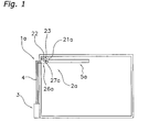
- FIG. 1 An air conditioner 1a according to the first embodiment of the present invention is depicted in FIG. 1.
- This air conditioner 1a comprises an indoor unit 2a and an outdoor unit 3, and is capable of air conditioning, such as cooling and heating, a room by radiating and by blowing out temperature adjusted air.
- FIG. 1 depicts part of the air conditioner 1a as a cross sectional view.
- the outdoor unit 3 is disposed outdoors, and comprises a compressor 31, a four-way switching valve 32 , a motor operated valve 33, an outdoor fan (not shown), an outdoor fan motor 34, an outdoor unit temperature sensor 35 (refer to FIG. 4 for the above), an outdoor heat exchanger (not shown), and the like.
- the compressor 31, the motor operated valve 33, the four-way switching valve 32, the outdoor heat exchanger, and the like constitute an indoor heat exchanger (discussed later) and a refrigerant circuit.
- the outdoor fan motor 34 rotatably drives the outdoor fan, which generates a current of air that passes through the outdoor heat exchanger.
- the outdoor unit temperature sensor 35 includes various temperature sensors that detect the temperature of the outdoor heat exchanger, the temperature of the outdoor air, and the like.
- the indoor unit 2a is disposed in the room at the vicinity of the ceiling surface, on a side wall, or the like, and comprises an indoor unit casing 21a, an indoor heat exchanger 22 (temperature adjusting unit), an indoor fan 23 (ventilating part), an indoor fan motor 24 (refer to FIG. 4), an indoor unit temperature sensor 25 (refer to FIG. 4), a radiation panel structure 5a, and the like.
- the indoor unit casing 21 a internally houses the indoor heat exchanger 22, the indoor fan 23, and the like, and comprises an inlet 26a and a connection port 27a (ventilation port).
- the inlet 26a is an opening through which passes the air taken in from the room into the indoor unit casing 21a.
- the connection port 27a is an opening through which passes air sent from inside the indoor unit casing 21 a through the indoor heat exchanger 22 to the radiation panel structure 5a, and is connected to an air intake 51 of the radiation panel structure 5a, which is discussed later.
- the indoor heat exchanger 22 is connected via a refrigerant piping 4 to the outdoor heat exchanger, the compressor 31, and the like.
- the indoor heat exchanger 22 adjusts the air temperature by exchanging heat with the air that passes therethrough.
- the indoor fan motor 24 rotatably drives the indoor fan 23, which generates an air current that is taken in from the room and sent to the radiation panel structure 5a.
- This air current is a current of air that is taken in from the inlet 26a into the indoor unit casing 21a, passes through the indoor heat exchanger 22, the connection port 27a, and the air intake 51, and arrives inside the radiation panel structure 5a.
- the indoor unit temperature sensor 25 includes various temperature sensors that detect the temperature of the indoor heat exchanger, the temperature of the indoor air, and the like.
- the radiation panel structure 5a is disposed in the vicinity of the ceiling surface, and performs air conditioning, such as heating and cooling, by radiation using the temperature of the temperature adjusted air, and by blowing out the temperature adjusted air.
- air conditioning such as heating and cooling
- the constitution of the radiation panel structure 5a will be discussed later in detail.
- the air conditioner 1a comprises a control unit 6 (a first control unit and a second control unit).
- the control unit 6 is disposed split between the outdoor unit 3 and the indoor unit 2a, and controls the operation of the air conditioner 1a.
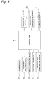
- the control unit 6 is connected to components such as the compressor 31, the four-way switching valve 32 , the motor operated valve 33, the outdoor fan motor 34, the outdoor unit temperature sensor 35, the indoor fan motor 24, the indoor unit temperature sensor 25, and the like, as depicted in FIG. 4. If the control unit 6 receives an operation command from a remote control 7, then it controls the operation of the air conditioner 1a by controlling the various components.
- FIG. 2 depicts an external view of the radiation panel structure 5a.
- the radiation panel structure 5a has a thin, plate shaped external form, and is flatly shaped. In addition, the radiation panel structure 5a is disposed in the vicinity of the ceiling surface and parallel to the ceiling surface. Consequently, with respect to the living space below, the radiation panel structure 5a has a projected area that is larger than in other directions.
- the radiation panel structure 5a comprises the air intake 51, a radiation part 52a (pressure generating space component), a plurality of shape supporting members 53a, and the like.
- the air intake 51 is the portion where the temperature adjusted air is taken in, and is an opening provided on one of the side surfaces of the radiation panel structure 5a.
- the air intake 51 is detachably connected to the connection port 27a of the indoor unit casing 21a, and the air sent by the indoor fan 23 (refer to the outline arrow A1) passes therethrough.
- the radiation part 52a comprises a first radiation surface 54 (first part), a second radiation surface 55 (second part), and three side surfaces 56, and internally constitutes a pressure generating space PS wherein a pressure greater than the atmospheric pressure is generated by the air.
- the first radiation surface 54 has a quadrilateral, thin, sheet shape, and closes the lower part of the pressure generating space PS.
- the first radiation surface 54 is disposed parallel to the ceiling surface at a position facing the living space of the room.
- the first radiation surface 54 is made of a woven fabric having a radiation rate of approximately 0.9.
- the second radiation surface 55 is shaped the same as the first radiation surface 54, and closes the upper part of the pressure generating space PS.
- the second radiation surface 55 is disposed opposing the first radiation surface 54 at a position facing the ceiling surface. Namely, the second radiation surface 55 is disposed between the first radiation surface 54 and the ceiling surface.
- the second radiation surface 55 is made of a woven fabric the same as the first radiation surface 54.
- the three side surfaces 56 each have a long rectangular shape, and close the side parts of the pressure generating space PS, excluding the air intake 51.
- the three side surfaces 56 are respectively connected to the three sides of the first radiation surface 54 and the three sides of the second radiation surface 55.
- the three side surfaces 56 are made of a woven fabric the same as the first radiation surface 54 and the second radiation surface 55.
- the radiation panel structure 5a has a closed bag shape.
- the plurality of shape supporting members 53a are thread shaped members disposed spaced apart. Each of the plurality of shape supporting members 53a is the same length, with one end fixed to the first radiation surface 54, and the other end fixed to the second radiation surface 55. The plurality of shape supporting members 53a is disposed substantially evenly on the flat surfaces of the first radiation surface 54 and the second radiation surface 55. If a pressure greater than the atmospheric pressure is generated in the pressure generating space PS, then the shape supporting members 53a maintain the first radiation surface 54 and the second radiation surface 55 as flat shapes, thereby maintaining the radiation part 52a as a plate shape. Furthermore, symbols are affixed only to one of the shape supporting members 53a in FIG. 2, and are omitted from the other shape supporting members 53a.
- the indoor heat exchanger 22 functions as an evaporator, and captures the heat from the air passing therethrough.
- the heat from the air in the room taken in by the indoor fan 23 from the inlet 26a into the indoor unit casing 21a is captured when it passes through the indoor heat exchanger 22, and is thereby cooled.
- this cooled air passes through the connection port 27a and the air intake 51, and is sent to the pressure generating space PS inside the radiation part 52a.
- a positive static pressure greater than the atmospheric pressure is generated in the pressure generating space PS.
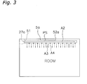
- a pressure greater than the atmospheric pressure is generated in a direction perpendicular to the current of air flowing parallel to the ceiling surface (refer to the solid arrow A2). Consequently, the cooled air is pushed out from the gaps between the fibers of the woven fabric of the radiation part 52a, and gently blown out into the room (refer to the solid arrow A3).
- the radiation part 52a is cooled by making contacting with the cooled air. Consequently, cold radiation is generated by the radiation part 52a (refer to the broken arrow A4).
- the indoor heat exchanger 22 functions as a condenser, and heats the air passing therethrough.
- the heated air is sent to the pressure generating space PS inside the radiation part 52a, the same as during cooling operation. Further, the heated air is pushed out from between the fibers of the woven fabric, and gently blown out into the room.
- the radiation part 52a is heated by making contacting with the heated air. Further, heat radiation is generated by the radiation part 52a.
- the room is heated by the heat radiation of the radiation part 52a.
- the room can be cooled and heated by radiation and the gentle blow out of air, as described above. Consequently, the discomfort caused by drafts can be eliminated.
- this air conditioner 1a By increasing the surface area of the first radiation surface 54 with this air conditioner 1a, it is possible to radiate and to gently blow out air from the vicinity of the ceiling surface toward a large area of the living space of the room. Consequently, the entire room can be heated or cooled substantially evenly. Thereby, it is possible to prevent the generation of an uncomfortable temperature differential between places in the room. Accordingly, the discomfort of the occupants and the like can be eliminated with this air conditioner 1a. In addition, even if there are a plurality of occupants and the like in the room, it is possible to generate a comfortable temperature environment for many occupants and the like.
- the radiation panel structure 5a is disposed in the vicinity of the ceiling surface, and has a thin, plate shape. Consequently, even if the surface area of the first radiation surface 54 facing the living space is made relatively large, there is little risk of it interfering with the occupants and the like.
- This air conditioner 1a performs both heating and cooling by radiation and heating and cooling by blowing out. Consequently, the convection performance by blowing out can be reduced more than the case wherein heating and cooling of the room is performed only by blowing out.
- the radiation part 52a is made of a woven fabric, which has a radiation rate of approximately 0.9. Consequently, even though it is a woven fabric, the heating and cooling of the room by radiation can be performed with sufficient effectiveness.
- the air blown out from the gaps between the fibers of the woven fabric make the temperature up to the outer side of the first radiation surface 54 the same as the temperature inside the radiation part 52a. Consequently, the heating and cooling of the room by radiation can be performed efficiently.
- the radiation part 52a which is made of woven fabric, tends to bulge and approach a cylindrical shape if a pressure greater than the atmospheric pressure is generated in the pressure generating space PS. In this case, there is a risk that the flat shape of the abovementioned type of radiation part 52a will not be maintained.
- the distance between the first radiation surface 54 and the second radiation surface 55 is maintained by the shape supporting members 53a. Consequently, bulging of the flexible first radiation surface 54 and second radiation surface 55 is suppressed, and their flat shapes can be maintained.
- the plurality of shape supporting members 53a is provided substantially evenly on the flat surfaces of the first radiation surface 54 and the second radiation surface 55. Consequently, the flat shape of the radiation part 52a can be maintained with greater precision.
- the abovementioned shape supporting members 53a are thread shaped members, but may be strip shaped members or rigid, pole shaped members, and can achieve the effect of holding the shape of the radiation part 52a.
- the shape supporting members 53a are made of a thread shaped flexible material.
- the radiation panel structure 5a is detachably attached to the connection port 27a of the indoor unit casing 21a. Consequently, it is easy to detach and reattach the radiation panel structure 5a from and to the indoor unit casing 21a. Accordingly, the installation work and the maintenance of the radiation panel structure 5a are easy.
- the radiation part 52a is made of a woven fabric. Consequently, if dirt adheres to the radiation part 52a, then it can be cleaned by detaching the radiation panel structure 5a.
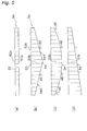
- FIG. 5(b) depicts a side view of a radiation panel structure 5b according to the second embodiment of the present invention.
- This radiation panel structure 5b comprises a plurality of shape supporting members 53b, the same as the radiation panel structure 5a according to the first embodiment.
- each of the plurality of shape supporting members 53a is the same length. Consequently, as depicted in FIG. 5(a), the first radiation surface 54 and the second radiation surface 55 are substantially parallel, and the radiation part 52a is maintained in a flat shape.
- each of the plurality of shape supporting members 53b is not the same length, but rather has differing lengths so that a radiation part 52b has an arbitrary shape. Namely, as depicted in FIG.
- the length of the shape supporting members 53b increases, in a side view, toward the center, and the length increases as a linear function advancing from the side end to the center. Consequently, when air is taken into the pressure generating space PS, the first radiation surface 54 bulges increasingly downward the closer the position to the center thereof.
- two inclined surfaces 540, 541 that sandwich the center are formed in the first radiation surface 54. These two inclined surfaces are connected at the center of the first radiation surface 54, and are respectively inclined downward toward the center of the first radiation surface 54.
- symbols are affixed to only one of the shape supporting members 53b and are omitted from the other shape supporting members 53b.
- a curved surface in a side view, is formed in the first radiation surface 54 that is smoothly curved downwardly convex. This curved surface is curved so that the center of the first radiation surface 54 bulges downward.
- the radiation part 52a is flatly formed as depicted in FIG. 5(a), then a difference in the radiation quantity arises depending on the position of the occupants and the like who are below the first radiation surface 54.
- the shape factor which affects the radiation quantity, differs for the case in which the occupants and the like are at the center of the first radiation surface 54 and for the case in which the occupants and the like are at the edges of the first radiation surface 54. Consequently, a difference in the radiation quantity received by the occupants and the like differs for the case in which the occupants and the like are below the center of the first radiation surface 54 and for the case in which the occupants and the like are below the edges of the first radiation surface 54. Specifically, the radiation quantity is greatest at the vicinity of the center, and decreases toward the edges.
- the plurality of shape supporting members 53b maintains the radiation part 52b in the shape as described above, and it is possible to thereby change the direction of radiation (refer to the solid arrows A5, A6). Accordingly, the shape factor of the radiation part 52b can be made substantially equal with respect to an arbitrary location of the room. Thereby, the radiation quantity can be made substantially the same for the case in which an occupant is at the center of the first radiation surface 54 and for the case in which an occupant is at an edge of the first radiation surface 54. Accordingly, with this radiation panel structure 5b, the plurality of shape supporting members 53b enables a more uniform adjustment of the room temperature.
- the shape supporting members in a side view, lengthen the more they are positioned toward the left side, and the length of the shape supporting members increase as a linear function of advancing from the right side to the left side. Consequently, the first radiation surface 54 is inclined so that it slopes downward to the left side.
- a substantially uniform radiation quantity is provided to the right side space of the indoor space below the radiation part 52b. Accordingly, if, for example, the space on the right side of the indoor space is the principle occupative area, then a more uniform temperature environment can be created than for occupants and the like at the peripheral space. Thereby, the comfort of the occupants and the like can be further increased.
- the inclination angle and the curvature of the first radiation surface 54 can be more finely adjusted by changing the length and spacing of the abovementioned shape supporting members 53b. Accordingly, it is possible to make the first radiation surface 54 a shape so that it faces the direction where the temperature adjustment is needed. Consequently, it is possible to radiate and to blow out in a direction appropriate to the size of the room, the position of the occupants and the like, and so on.
- the shape of the radiation part 52b can be maintained in an arbitrary shape so that a comfortable temperature environment is created.
- the shape of the radiation part 52b is also acceptable to determine the shape of the radiation part 52b from the viewpoint of design rather than the viewpoint of radiation quantity adjustment. Namely, by adjusting the length of the shape supporting members 53b, it is acceptable to reflect a designed shape in the radiation part 52b that visually stimulates the occupants and the like.
- the coarseness of the fiber weave of the first radiation surface 54 and the second radiation surface 55 varies by the portion. Specifically, a plurality of fine fiber weave portions and a plurality of coarse fiber weave portions are alternately disposed in the first radiation surface 54 (refer to FIG. 6). In addition, the coarseness of the fiber weave of the second radiation surface 55 varies by portion the same as in the first radiation surface 54.
- FIG. 6 depicts a side view of the radiation panel structure 5c in a state wherein air has been sent into a radiation part 52c.
- the radiation part 52a in the radiation panel structure 5a according to the first embodiment is capable of collecting undesirable substances, such as dust, viruses, and pollen, included in the air that passes through the gaps between the fibers of the woven fabric.
- this radiation panel structure 5a when the air from the pressure generating space PS passes through the gaps between the fibers of the radiation part 52a and is blown out to the indoor space, the undesirable substances included in the air can be collected by the inner surfaces of the radiation part 52a, as depicted in FIG. 3. Namely, because the radiation part 52a is made of woven fabric, undesirable substances can be collected by the weave of the woven fabric. Consequently, with this radiation panel structure 5a, the undesirable substances can be eliminated from the air sent to the room, and the air in the room can thereby be cleanly maintained.
- the present invention can also be applied to an air conditioner that takes in air from the outdoors and sends it to the radiation panel structure.
- an air conditioner it is often the case that undesirable substances of the types mentioned above are included in the air. Consequently, the present invention, which is capable of collecting undesirable substances, is particularly effective.
- the radiation part 52a in the radiation panel structure 5a according to the first embodiment contains an active ingredient that eliminates unpleasant substances included in the air that passes between the fibers.
- an active ingredient that eliminates unpleasant substances included in the air that passes between the fibers.
- deodorizers, bactericides, and the like can eliminate odor causing chemical components and microorganisms from the air blown out from the pressure generating space PS into the room. It is acceptable to include such active ingredients in the woven fabric of the radiation part 52a, or to provide, separate from the woven fabric, a member that blows out active ingredients on the upstream side of the air blown out into the room.
- the active ingredients possessed by the radiation part 52a can eliminate unpleasant substances included in the air that passes between the fibers of the woven fabric. Consequently, the air sent into the room can be deodorized and disinfected, and clean air can be blown out into the room. Thereby, the comfort of the occupants and the like in the room can be enhanced.
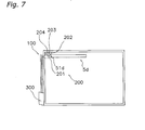
- FIG. 7 depicts a radiation panel structure 5d according to the sixth embodiment of the present invention.
- This radiation panel structure 5d is detachably connected to an existing convection type air conditioner 100.
- the convection type air conditioner 100 is a separate type air conditioner divided into an indoor unit 200 and an outdoor unit 300, and the indoor unit 200 is disposed on a side wall, in the vicinity of the ceiling surface, or the like, of the room.
- This convection type air conditioner 100 comprises refrigerant circuit components, such as an indoor heat exchanger 204, and an outdoor heat exchanger (not shown), the same as the air conditioner 1a according to the first embodiment, and constitutes a refrigerant circuit between the outdoor unit 300 and the indoor unit 200.
- the indoor unit 200 comprises an indoor unit casing 201, an indoor fan 203, and the like.
- the indoor unit casing 201 comprises an outlet 202 through which passes temperature adjusted air.
- the indoor fan 203 generates a current of air that is taken in from the room, passes through the indoor heat exchanger 204, and is blown out from the outlet 202.
- the convection type air conditioner 100 adjusts the temperature of the air taken into the indoor unit 200, and blows out temperature adjusted air from the outlet 202 provided in the indoor unit 200.
- this convection type air conditioner 100 can cool and heat a room on its own by blowing out temperature adjusted air from the outlet 202 into the room.
- the radiation panel structure 5d is connected to the outlet 202 of the convection type air conditioner 100.
- an air intake 51d of the radiation panel structure 5d is structured connectable to the outlet 202 of an existing convection type air conditioner 100.
- this air intake 51d and outlet 202 are detachable.
- This radiation panel structure 5d can be connected to an existing convection type air conditioner 100. Accordingly, an air conditioner having the same performance as the air conditioner 1a according to the first embodiment can be easily constituted just by attaching the radiation panel structure 5d. Consequently, an existing convection type air conditioner 100 can be effectively utilized.
- the existing convection type air conditioner 100 and the radiation panel structure 5d are detachable, the radiation panel structure 5d can be easily attached and detached. Consequently, maintenance, such as cleaning and replacement, of the radiation panel structure 5d can be easily performed.
- the present invention can be applied to a radiation panel structure capable of collecting undesirable substances, such as dust, viruses, and pollen, and maintenance, such as internal cleaning, of the radiation panel structure can thereby be easily performed.
- FIG. 8(a) depicts a side view of a radiation panel structure 5e according to the seventh embodiment of the present invention.
- the radiation panel structure 5e comprises a guide mechanism 57 (a modifying part).
- the guide mechanism 57 is provided in a radiation part 52e, and expands and contracts the radiation part 52e along the direction in which the air is blown in (refer to the outline arrow A9).
- This guide mechanism 57 expands and contracts the radiation part 52e into accordion-like folds, as depicted in FIG. 8(b).
- the guide mechanism 57 can increase or decrease the surface area of the first radiation surface 54 and the second radiation surface 55 by expanding and contracting the radiation part 52e.
- the guide mechanism 57 can increase and decrease the surface area of the radiation part 52e.
- the guide mechanism 57 can contract the portion of the radiation part 52e from the air intake 51 to the center, and can maintain the portion from the center to the tip in a flat shape.
- the surface area of the radiation part 52e is approximately half that of the state before contracting.
- the radiation panel structure 5e can change the surface area of the first radiation surface 54 and the second radiation surface 55 by expanding and contracting the radiation part 52e. Furthermore, the radiation quantity and the quantity of temperature adjusted air blown out can be adjusted by changing the surface area of the first radiation surface 54 and the second radiation surface 55. In addition, the range over which heating and cooling is performed can also be adjusted.
- expansion and contraction of such a radiation part 52e may be performed manually or automatically. If expansion and contraction is performed automatically, then a drive mechanism (not shown) that drives the guide mechanism 57 is further provided. In addition, by controlling the drive mechanism with the control unit 6, the surface area of the radiation part 52e can also be automatically adjusted in accordance with the operating status, such as whether cooling or heating is being performed.
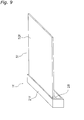
- FIG. 9 depicts an external view of one part of an air conditioner 1f according to the eighth embodiment of the present invention.
- a radiation panel structure 5f comprises the guide mechanism 57 that expands and contracts a radiation part 52f, the same as the radiation panel structure 5f according to the seventh embodiment.
- an indoor unit casing 21f (the housing part) is provided with a housing opening 28 for housing the radiation panel structure 5f.
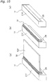
- the radiation panel structure 5f becomes smaller by the contraction of the radiation part 52f by the guide mechanism 57, as depicted in FIG. 10(a) and FIG. 10(b). Furthermore, as depicted in FIG. 10(c), the radiation panel structure 5f is housed inside the indoor unit casing 21f through the housing opening 28. Conversely, during operation of the air conditioner If, the housed radiation panel structure 5f is taken out and the radiation part 52f is expanded.
- the radiation panel structure 5f it is also acceptable for the radiation panel structure 5f to be expanded and contracted by the guide mechanism 57 rolling up the radiation part 52f into a cylindrical shape, as depicted in FIG. 11 (a).
- the radiation panel structure 5f becomes smaller by the guide mechanism 57 curling up the radiation part 52f into a cylindrical shape.
- the radiation panel which has become smaller, is housed inside the indoor unit casing 21f from the housing opening 28.
- the radiation part 52f is also acceptable for the radiation part 52f to be folded into strips.
- the guide mechanism 57 can reduce the size of the radiation panel structure 5f, and can house it in the indoor unit casing 21f. Consequently, by housing the radiation panel structure 5f beforehand, the radiation panel structure 5f does not interfere with the occupants and the like when operation of the air conditioner 1f is stopped. In addition, during operation of the air conditioner 1f, taking the radiation panel structure 5f out of the indoor unit casing 21f and expanding it enables the room temperature to be adjusted once again.
- the present invention is not limited to the case wherein the radiation panel structure 5f is housed in the indoor unit casing 21f, and the radiation panel structure 5f may also be provided with a housing part that houses the radiation part 52f. Effects the same as those described above can also be achieved in this case.
- control is performed as depicted in FIG. 12 in the air conditioner 1a of the first embodiment.
- the control unit 6 receives an operation stop command when the air conditioner 1a is performing cooling operation, then the control unit 6 performs drying control prior to stopping the operation of the air conditioner 1a. Drying control suppresses the generation of condensation by the radiation part 52a.
- air of a temperature higher than the room temperature is sent to the radiation part 52a by the control unit 6 controlling the indoor fan 23 and the temperature of the air sent to the pressure generating space PS of the radiation part 52a. Thereby, the generation of condensation in the radiation part 52a can be suppressed.
- step S1 if the control unit 6 receives operation stop command of an air conditioner 1a from the remote control and the like, then processing proceeds to step S2.
- step S2 a timer is started, and the counting of time T is started. Then, processing proceeds to step S3.
- step S3 drying operation is performed at a temperature higher than the indoor temperature. Namely, with this drying operation, air of a temperature higher than the room temperature is sent to the radiation part 52a. Thereby, the radiation part 52a is heated and dried.
- step S4 the value of time T is decremented; in step S5, the process judges whether time T has reached zero, i.e., whether the count has ended. If the count has not ended, then processing returns to step S3, and drying operation continues. If the count has ended, then the operation of the air conditioner 1a is stopped in step S6.
- the abovementioned time T is an empirically derived drying time.
- the surface temperature of the radiation part 52a falls due to the cold air blown out from the surface of the radiation part 52a. Furthermore, even immediately after the air conditioner 1a has stopped cooling operation, the surface of the radiation part 52a maintains a low temperature. Consequently, immediately after the air conditioner 1a stops cooling operation, the surface of the radiation part 52a makes contact with the indoor air having a high ambient humidity, which tends to generate condensation on the radiation part 52a.
- the control unit 6 performs a drying control that reduces the wetting of the radiation part 52a.
- drying control the control unit 6 blows out air, for a fixed time period, of a temperature higher than the room temperature prior to stopping the air conditioner 1a, as described above, and then stops the operation of the air conditioner 1a. Accordingly, the surface of the radiation part 52a is heated prior to stopping operation of the air conditioner 1a. Consequently, with this air conditioner 1a, the generation of condensation by the radiation part 52a can be prevented.
- drying control is not limited to the case wherein drying operation is performed for just a predetermined time period as described above, and it is also acceptable to determine the time period for performing drying operation by detecting the temperature of the vicinity of the outer side of the radiation part 52a.
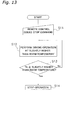
- FIG. 13 depicts a flow chart of drying control for this case.
- step S11 if the control unit 6 receives an air conditioner 1a operation stop command from the remote control and the like, then processing proceeds to step S12.
- step S12 drying operation is performed at a temperature slightly higher than the indoor temperature. Thereby, the radiation part 52a is heated.
- step S13 the process judges whether the temperature Th of the air in the vicinity of the outer side of the radiation part 52a is greater than or equal to, or slightly higher than the room temperature. Namely, in step S13, the process judges whether the temperature of the air in the vicinity of the outside of the radiation part 52a is higher than the room temperature by a prescribed temperature or greater. If the air temperature is low, then processing returns to step S12 and drying operation continues. If the air temperature is sufficiently high, then operation of the air conditioner 1a is stopped in step S14.
- drying control it is effective to perform drying control not only for the case wherein cooling operation is performed as described above, but also for cases where other operations are performed.
- the abovementioned drying control can prevent the generation of condensation by the radiation part for the case where outdoor high humidity air is taken in and blown out, for the case where air from the outdoors is taken in during the winter, and the like.
- drying control is not limited to the objective of heating the radiation part 52a as described above, but may also be performed with the objective of drying the moisture included in the woven fabric of the radiation part 52a.
- control unit 6 controls the indoor fan 23 so that air is sent to the radiation panel structure 5a with a 1/f fluctuation.
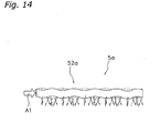
- FIG. 14 depicts one part of the radiation panel structure 5a for the case where such control is performed.
- this air conditioner air with a fluctuation of 1/f is sent to the radiation part 52a.
- the radiation part 52a is made of woven fabric that is flexible
- the first radiation surface 54 and the second radiation surface 55 fluctuate with a rhythm of 1/f due to air fluctuations. Accordingly, as depicted by the solid arrows and the broken arrows in the figure, the radiation direction and the distance of the radiation, and the blow out direction vary with a rhythm of 1/f. Thereby, comfort can be enhanced by impinging the occupants and the like with a natural feeling.
- the fluctuation of the first radiation surface 54 can also provide the occupants and the like with visually natural aesthetics. As described above, this air conditioner can enhance the comfort of the occupants and the like in the room.
- FIG. 15 and FIG. 16 depict an air conditioning system S1 according to the eleventh embodiment of the present invention.
- FIG. 15 is a side view of the air conditioning system S1, and a room R wherein the air conditioning system S1 is disposed; and
- FIG. 16 is a cross sectional view taken along the XVI-XVI line in FIG. 15.
- This air conditioning system S1 comprises a transport pathway SP1 and an air conditioner 1i.
- a bed B is provided in the room R.
- This bed B is, for example, a bed, and is disposed in the room R, such as a bedroom.
- the air conditioner 1i adjusts the temperature of the room R wherein the bed B is disposed.
- the transport pathway SP1 is a space adjacent to the room R and that communicates with the lower part of the room R.
- the transport pathway SP1 is adjacent to a side of the room R, and houses an indoor unit 2i.
- the room R and the transport pathway SP1 are partitioned by a partition W.
- the partition W is provided extending from a floor F of the room R to a ceiling surface CL, and air can enter and exit between the room R and the transport pathway SP1.
- the transport pathway SP1 can take in air from the lower part of the room R and transport it to the indoor unit 2i.
- the transport pathway SP1 may be a space dedicated to the transport of air for air conditioning, and may also use a housing space, such as a closet provided in a side surface of the room R.
- the air conditioner 1i comprises a radiation panel structure 5i, the indoor unit 2i, and the outdoor unit 3 (refer to FIG. 22), and is capable of air conditioning, such as heating and cooling, the room R by radiation and by blowing out temperature adjusted air.
- the radiation panel structure 5i is disposed in the vicinity of the ceiling surface CL along the ceiling surface CL, and performs air conditioning, such as heating and cooling, by radiation using the temperature of the temperature adjusted air, and by blowing out temperature adjusted air.
- the overall radiation panel structure 5i has a thin, plate shaped outline, and is flatly shaped.
- One side surface of the radiation panel structure 5i is proximate to the partition W, and is connected to the indoor unit 2i inside the transport pathway SP1.
- the radiation panel structure 5i comprises a radiation part 52i and an external frame 4i.
- the radiation part 52i is the portion that radiates, and that blows out air.
- FIG. 17 depicts an external view of the radiation part 52i.
- FIG. 17(a) is a plan view of the radiation part 52i
- FIG. 17(b) is a side view of the radiation part 52i.
- the plan view of the radiation part 52i of FIG. 17(a) is a view looking up from below at the radiation part 52i installed in the ceiling surface CL.
- the radiation part 52i has a thin, plate shaped outline, and is flatly shaped.
- the radiation part 52i is disposed proximate to the ceiling surface CL of the room R, and has a rectangular outline shape in a plan view.
- the radiation part 52i has a size that substantially planarly covers the bed B, and is disposed directly above the bed B.
- the radiation part 52i comprises a bag part 53i, an internal frame 57i (the frame part) (refer to FIG. 19 and FIG. 20), and a heat insulating material 58i.
- the bag part 53i is disposed directly above the bed B in the vicinity of the ceiling surface CL and substantially parallel to the ceiling surface CL, and has a size that substantially planarly covers the bed B.
- the bag part 53i is bag shaped and made of a fiber material, such as woven fabric or non-woven fabric, and internally constitutes the pressure generating space PS, as depicted in FIG. 18.
- FIG. 18 depicts a side cross sectional view of the bag part 53i, but the internal frame 57i, and the like, are omitted.
- the sending of temperature adjusted air from the indoor unit 2i generates a pressure greater than the atmospheric pressure in the pressure generating space PS.
- the fiber material that forms the bag part 53i is flexible, capable of transmitting air, and has a radiation rate of approximately 0.9. Consequently, the air sent to the pressure generating space PS is gently blown out from the gaps in the weave of the bag part 53i. In addition, by adjusting the temperature of the bag part 53i by the air sent to the pressure generating space PS, radiation is generated from the bag part 53i. Thereby, the room R can be temperature adjusted by radiation and by the gentle blowing out of air. Furthermore, the fiber material is elastic.
- the bag part 53i has a flat, thin plate shape, and comprises the second radiation surface 55, the first radiation surface 54, and the side surfaces 56.
- the second radiation surface 55 of the bag part 53i is the upper surface of the bag part 53i, and is disposed along the ceiling surface CL of the room R substantially parallel to the ceiling surface CL. In addition, the second radiation surface 55 of the bag part 53i is disposed proximate to the ceiling surface CL.
- the first radiation surface 54 of the bag part 53i is the lower surface of the bag part 53i, and is disposed at a position facing the room R and substantially parallel to the ceiling surface CL.
- the first radiation surface 54 of the bag part 53i has a rectangular projected shape with respect to the room R below, as depicted in FIG. 17(a) and has a size on the order that, for example, planarly covers the bed B disposed in the room R.
- the side surfaces 56 of the bag part 53i are each long, thin, and rectangular shaped, as depicted in FIG. 17(b). Radiation and the blow out of air are also generated from the side surfaces 56 of the bag part 53i, the same as from the second radiation surface 55 and the first radiation surface 54, and the radiation and blow out of air from the side surfaces 56 of the bag part 53i are collected in a desired direction by the external frame 4i.
- the external frame 4i is explained later in detail.
- one of the side surfaces 56 of the bag part 53i is provided with an internal frame insertion hole 560, which is an opening through which the internal frame 57i is inserted; and an open/close part 561 that opens and closes the internal frame insertion hole 560.
- the open/close part 561 comprises a fastener that opens and closes the internal frame insertion hole 560.
- one of the side surfaces 56 of the bag part 53i is provided with an air intake 51.
- the air intake 51 is a portion wherein temperature adjusted air is taken in; the air intake 51 is connected to one end of a duct 9, whose other end is attached to an outlet 27i of the indoor unit 2i, and air sent from the indoor unit 2i to the pressure generating space PS passes therethrough.
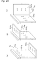
- the internal frame 57i is a member that is disposed inside the bag part 53i and that supports the bag part 53i in a thin, plate shape of the type described above.
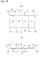
- FIG. 19 depicts an external view of the internal frame 57i.
- FIG. 19(a) is a plan view of the internal frame 57i, and is a view of the internal frame 57i from the ceiling surface CL side.
- the internal frame 57i comprises a plurality of linear members L1- L6 combined in a flat shape.
- the plurality of linear members L1- L6 is each made of, for example, a member having a prescribed rigidity, such as a metal like stainless steel, a resin, and the like.
- the internal frame 57i is formed as a separate body from the bag part 53i, and the bag part 53i is detachable from the internal frame 57i.
- an upper surface 58 of the internal frame 57i has a substantially rectangular outline shape, and comprises the two first linear members L1 that constitute the two long sides of the rectangle, and the plurality of second linear members L2 provided across the two first linear members L1.
- Two of the plurality of second linear members L2 constitute the short sides of the rectangle, and the other second linear members L2 are disposed substantially equispaced and parallel to the short sides of the rectangle.
- the second linear members L2 are made slightly longer than the spacing of the first linear members L1, and protruding parts 570 are consequently formed on both sides of each of the second linear members L2 and protrude slightly from the first linear members L1, i.e., the long sides of the rectangle.
- the upper surface 58 of this internal frame 57i maintains the second radiation surface 55 of the bag part 53i in a shape of the type described above.
- a lower surface 59 of the internal frame 57i comprises the third linear members L3 combined in a rectangular shape of a size the same as the outline shape of the upper surface 58 of the internal frame 57i, the fourth linear members L4 combined in a rectangular shape slightly smaller than the outline shape of the upper surface 58 of the internal frame 57i, and the fifth linear members L5 that join the third linear members L3 and the fourth linear members L4.
- the lower surface 59 of this internal frame 57i maintains the first radiation surface 54 of the bag part 53i in a shape of the type described above.
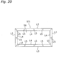
- FIG. 20 is a cross sectional view taken along the XX-XX line in FIG. 19(b).
- side surfaces 60 of the internal frame 57i comprise the plurality of sixth linear members L6 that connects the upper surface 58 and the lower surface 59 of the internal frame 57i.
- the side surfaces 60 of this internal frame 57i maintain the side surfaces 56 of the bag part 53i in a shape of the type described above.
- the internal frame 57i is inserted from the internal frame insertion hole 560 of the bag part 53i depicted in FIG. 17(a) to the interior of the bag part 53i.
- the dimensions of the bag part 53i and the internal frame 57i are designed so that a predetermined tension acts upon the bag part 53i by closing the fastener of the open/close part 561 in a state with the internal frame 57i disposed inside the bag part 53i.
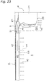
- the heat insulating material 58i is fixed to the upper surface positioned on the ceiling surface CL side of the radiation part 52i, i.e., to the second radiation surface 55 of the bag part 53i, and is provided on the ceiling surface CL side of the pressure generating space PS.
- a gap of approximately 6 mm is provided between the second radiation surface 55 of the bag part 53i and the ceiling surface CL, and the heat insulating material 58i is fixed to the second radiation surface 55 of the bag part 53i, and faces this gap.
- the heat insulating material 58i is sheet shaped and has a thickness of approximately 5 mm, and the gap between the heat insulating material 58i and the ceiling surface CL is extremely small. Accordingly, the heat insulating material 58i is proximate to the ceiling surface CL.
- the heat insulating material 58i covers substantially the entirety of the second radiation surface 55 of the bag part 53i.
- the external frame 4i is a wood frame combined so that its outline is a rectangular shape with one short side missing, and surrounds the side surfaces of the radiation part 52i outside of the bag part 53i, i.e., the side surfaces 56 of the bag part 53i.
- the material that constitutes the external frame 4i is not limited to wood, and may be one having a prescribed rigidity capable of supporting the radiation part 52i. Excepting the side surface 56 wherein the air intake 51 of the bag part 53i is provided, i.e., excepting the side surface 56 facing the partition W, the external frame 4i surrounds all of the other side surfaces 56. Accordingly, the external frame 4i surrounds the entirety of the side surfaces 56 of the radiation part 52i facing the room R.
- the upper end of the external frame 4i is fixed to the ceiling surface CL without any gaps, and the lower end is of a height substantially the same as the first radiation surface 54 of the bag part 53i.
- the dimension of the external frame 4i in the height direction is approximately 60 mm, and the radiation panel structure 5i is extremely thin shaped. Accordingly, the radiation panel structure 5i reduces the feeling by the occupants and the like in the room R of being cramped.
- the shape of the first radiation surface 54 bulges convexly downward due to the self weight, internal pressure, and the like, of the bag part 53i, but the height of the external frame 4i is substantially the same as the position at which it connects with the first radiation surface 54, which forms the base of the bulge, and the side surfaces 56.
- the external frame 4i comprises support parts 40i that support the internal frame 57i.
- FIG. 21 is a cross sectional view taken along the XXI-XXI line in FIG. 16.
- a support part 40i is provided on both of the two long sides of the external frame 4i.
- Each support part 40i comprises a slit 41 i provided on the inner side of the external frame 4i, and a metal rail 42i provided in the slit 41i.
- the slit 41i is provided, within the inner side of the external frame 4i, at a position close to the ceiling surface CL, and is provided parallel to the ceiling surface CL.
- the protruding parts 570 of the internal frame 57i latch from the sides of the external frame 4i through these support parts 40i to the support parts 40i, and the radiation part 52i is thereby supported by the external frame 4i.
- the indoor unit 2i sends temperature adjusted air to the pressure generating space PS of the radiation part 52i.
- the indoor unit 2i is disposed in the transport pathway SP1 partitioned from the room R, is the upper part of the transport pathway SP1, and is disposed in the vicinity of the radiation panel structure 5i of the room R.
- the indoor unit 2i comprises the indoor heat exchanger 22, the indoor fan 23, the indoor fan motor 24, and an indoor unit casing 21i (refer to FIG. 15).
- the indoor unit casing 21i internally houses the indoor heat exchanger 22, the indoor fan 23, the indoor fan motor 24, and the like, and comprises an inlet 26i and the outlet 27i, as depicted in FIG. 18.
- the inlet 26i is an opening through which passes the air taken in from the room R into the indoor unit casing 21 i.
- the inlet 26i is provided in the lower surface of the indoor unit casing 21i, and is provided facing downward so that air from below is sucked in.
- the inlet 26i is disposed lower than the radiation part 52i, and is disposed lower than the outlet 27i.
- the indoor unit 2i is disposed in the transport pathway SP1, and the inlet 26i is provided so that air from the lower part of the room R is sucked in via the transport pathway SP1. If a housing space, such as a closet, is used as the transport pathway SP1, then the air in the room is sucked in from gaps in the housing space, and is sucked in from the inlet 26i of the indoor unit 2i into the indoor unit 2i.
- the outlet 27i is provided higher than the inlet 26i, and is an opening through which passes the air sent through the indoor heat exchanger 22 inside the indoor unit casing 21i to the radiation panel structure 5i.
- the outlet 27i is connected to one end of the duct 9, which is connected to the air intake 51 of the radiation panel structure 5i, and blows out the air of the indoor unit 2i in a substantially horizontal direction.
- the indoor heat exchanger 22 is connected via refrigerant pipings 29a, 29b to an outdoor heat exchanger 30, the compressor 32, and the like.
- the indoor heat exchanger 22 adjusts the temperature of the air by exchanging heat with the air passing therethrough.
- the indoor fan motor 24 rotatably drives the indoor fan 23, which generates a current of air that is taken in from the room R and sent to the radiation panel structure 5i. This air current is taken in from the inlet 26i into the interior of the indoor unit casing 21i, passes through the indoor heat exchanger 22, the outlet 27i and the air intake 51, and arrives at the pressure generating space PS inside the radiation part 52i.
- the outdoor unit 3 is disposed outdoors, and, as shown in FIG. 22, comprises the accumulator 31, the compressor 32, the four-way switching valve 32, the motor operated valve 33, an outdoor fan 38, an outdoor fan motor 39, the outdoor heat exchanger 30, and the like.
- the compressor 32, the motor operated valve 33, the four-way switching valve 32 , the outdoor heat exchanger 30, and the like, comprise the indoor heat exchanger 22 together with the refrigerant circuit.
- the outdoor fan motor 39 rotatably drives the outdoor fan 38, which generates a current of air that passes through the outdoor heat exchanger 30.
- the indoor heat exchanger 22 functions as an evaporator, and captures the heat from the air passing therethrough. As shown in FIG. 23, the heat of the room R air taken in by the indoor fan 23 from the inlet 26i via the transport pathway SP1 into the indoor unit casing 21 i (refer to the solid arrow A5) is captured when it passes through the indoor heat exchanger 22, and is thereby cooled.
- This cooled air is blown out from the outlet 27i, and sent through the duct 9 to the air intake 51 (refer to the solid arrow A6).
- This air blown out from the indoor unit 2i is sent to the pressure generating space PS inside the bag part 53i.
- a positive static pressure greater than the atmospheric pressure is generated in the pressure generating space PS. Namely, a pressure greater than the atmospheric pressure is generated in a direction perpendicular to the flow of air flowing parallel to the ceiling surface CL (refer to the solid arrow A2). Consequently, the cooled air is pushed out from the gaps between the fibers of the bag part 53i, and gently blown out into the room R (refer to the solid arrow A3).
- the bag part 53i is cooled when it makes contacts with the cooled air. Consequently, cold radiation is generated by the bag part 53i (refer to the broken arrow A4).
- the air of the room R is sucked in from the lower part of the room R into the transport pathway SP1, and is sucked in once again from the inlet 26i of the indoor unit 2i into the indoor unit 2i.
- the indoor heat exchanger 22 functions as a condenser, and heats the air passing therethrough.
- the heated air is sent to the pressure generating space PS inside the bag part 53i, the same as during cooling operation. Further, the heated air is pushed out from the gaps between the fibers of the bag part 53i, and is gently blown out into the room R.
- the bag part 53i is heated when it makes contact with the heated air. Further, heat radiation is generated by the bag part 53i.
- this air conditioning system S1 With this air conditioning system S1, the air sent from the indoor unit 2i to the radiation part 52i in the vicinity of the ceiling surface CL is blown out into the room R, circulates in the room R, returns to the indoor unit 2i, and is once again blown out from the radiation part 52i, as described above. Consequently, with this air conditioning system S1, it is possible to ensure the circulation of air circulating in the room R.
- the outlet 27i of the indoor unit 2i is provided higher than the inlet 26i.
- the outlet 27i is connected to the radiation part 52i provided in the vicinity of the ceiling surface CL; however, with this indoor unit 2i, the outlet 27i is provided above, making it easy to connect the indoor unit 2i to the radiation part 52i provided in the vicinity of the ceiling surface CL.
- the indoor unit 2i can adequately suck in air from the space below, which has ample space compared with the space above.
- the indoor unit 2i is disposed in the transport pathway SP1 provided on a side of the room R, but an indoor unit 2j may be disposed in the floor F of the room R, as in an air conditioning system S2 depicted in FIG. 24.
- an inlet 26j is provided on the side of an indoor unit casing 21j, and sucks in air from the vicinity of the floor F of the room.
- the air sucked into the indoor unit 2j is blown out from an outlet 27j, and sent to the radiation part 52i through a duct 91 that connects the outlet 27j with the air intake 51 of the radiation part 52i.
- the indoor unit 2j can suck in from the vicinity of the floor F the air that was blown out from the vicinity of the ceiling surface CL, and once again blow that air out from the vicinity of the ceiling surface CL. Consequently, according to this air conditioning system S2, circulation can be more favorably ensured, and the temperature can be more effectively adjusted.
- the indoor unit 2i is disposed at the upper part of the transport pathway SP1 provided on a side of the room R; however, as with an air conditioning system S3 depicted in FIG. 25, an indoor unit 2k may be housed in an indoor unit housing SP2 provided in the vicinity of the ceiling surface CL of the room R.
- This indoor unit housing SP2 projects from the ceiling surface CL into the room R so that it covers the indoor unit 2k, and is provided adjacent to the upper part of a side wall of the room R.
- the indoor unit 2k is constituted the same as the indoor unit 2i according to the first embodiment, and comprises an inlet 26k and an outlet 27k.
- the installation of the indoor unit 2k is easy, the same as in the first embodiment.
- the indoor unit housing SP2 can be formed relatively small, the work of installation in the room is simple, and more of the space in the room R can be utilized as living space.
- the indoor unit 2i is disposed in the transport pathway SP1 provided on a side of the room R, but an indoor unit 2m may be provided outdoors, as in an air conditioning system S4 depicted in FIG. 26.
- the indoor unit 2m sucks in air from the outdoors and sends it to the radiation part 52i.
- the indoor unit 2m is constituted the same as the indoor unit 2i according to the first embodiment, and comprises an inlet 26m and an outlet 27m.
- the installation of the indoor unit 2m is easy, the same as the air conditioning system S1 according to the eleventh embodiment. Namely, because the outlet 27m is provided above, it is easy to connect the outlet 27m with a duct 92, which extends from the radiation part 52i. Consequently, the installation of the indoor unit 2m is easy.
- an inlet may be provided on a wall surface of the room R, and connected to the inlet 26m of the indoor unit 2m via a duct, and the like.
- the temperature adjusted air is blown out from the vicinity of the ceiling surface CL of the room R, sucked in from the inlet of the side wall, and sent once again to the room R.
- favorable circulation can be ensured.
- the indoor unit 2i is disposed in the transport pathway SP1 provided on a side of the room R, but an indoor unit 2n may be housed behind the ceiling as in the air conditioning system S5 depicted in FIG. 27.
- the indoor unit 2n sucks in the air of the room R from an inlet 26n provided on the lower surface, and blows out temperature adjusted air from an outlet 27n in a substantially horizontal direction.
- the air blown out from the outlet 27n is sent to the radiation part 52i through a duct 93.
- the indoor unit 2n is provided behind the ceiling, the indoor unit 2n can be hidden from the visual field of the occupants and the like in the room R. Thereby, the aesthetics of the room R can be enhanced.
- the radiation panel structure 5a is disposed in the vicinity of the ceiling surface, but the radiation panel structure may be disposed along the vicinity of a side wall of the room.
- a radiation part 52g that is shaped bent midway may also be provided.
- the radiation part 52g may comprise a first flat surface 521g parallel to the side wall, and a second flat surface 522g that extends perpendicularly from the lower end of the first flat surface 521 g.
- the radiation part 52g may comprise a third flat surface 523g parallel to a side wall, and a fourth flat surface 524g that extends perpendicularly from the upper end of the third flat surface 523g.
- FIG. 28(a) the radiation part 52g may comprise a first flat surface 521g parallel to the side wall, and a second flat surface 522g that extends perpendicularly from the lower end of the first flat surface 521 g.
- the radiation part 52g may comprise a third flat surface 523g parallel to a side wall, and a fourth flat surface 524g that extends perpendicularly from the upper end of the third flat surface 523g.
- the radiation part 52g may comprise a fifth flat surface 525g parallel to a side wall, and a sixth flat surface 526g that extends perpendicularly from the side end of the fifth flat surface 525g and that is parallel to another side wall.
- the radiation part 52g is made of woven fabric, and it is consequently easy to shape the radiation part 52g bent midway.
- the radiation part 52a is a closed bag shape, excepting the air intake 51; however, as shown in FIG. 29, it may be shaped with the air intake 51 and the ceiling surface side open.
- This radiation part 52h comprises a first radiation surface 54 disposed in the vicinity of the ceiling surface opposing the living space of the room, and three side surfaces 56 that join the first radiation surface 54 and the ceiling surface.
- the first radiation surface 54 closes the lower part of the pressure generating space PS, and the three side surfaces 56 close the sides of the pressure generating space PS, excepting the air intake port.
- FIG. 29(a) is a side view of a radiation panel structure 5h seen from a direction perpendicular to the air current of the pressure generating space PS (solid arrow A2)
- FIG. 29(b) is a side view of the radiation panel structure 5h seen from the direction of the air current of the pressure generating space PS.
- the radiation panel structure 5h may comprise two side surfaces 56 instead of three.
- the side surface 56 perpendicular to the direction of the air flowing through the pressure generating space PS i.e., the side surface 56 positioned at the tip of the radiation part 52h
- the effect the same as mentioned above can be achieved by the generation of internal static pressure in a direction perpendicular to the air flowing through the pressure generating space PS.
- the side opposite the air intake 51 of the radiation part 52h is open, air from this portion can be blown out into the room. Consequently, the temperature adjusted air can be sent distantly. Accordingly, temperature adjusted air can be made to sufficiently reach the indoor space, thereby enabling the creation of a more comfortable temperature environment.
- the first radiation surface 54 and the second radiation surface 55 are flatly formed; however, if shaped in this manner, then the radiation panel structure 5a disposed in the vicinity of the ceiling surface may block the illumination, and the like. Accordingly, the radiation part 52a may be shaped so that it avoids the portion opposing the illumination, and the like. For example, the portion opposing the illumination, and the like, may be provided with an opening, a notch, or the like. In addition, if the radiation panel structure 5a is provided in the vicinity of a side wall, then it may be shaped to avoid the window, and the like. Thereby, the radiation panel structure 5a can prevent becoming an obstruction to the illumination, and the like.
- the radiation part 52a of the radiation panel structure 5a is made of woven fabric, it is easy to form it into a shape, unlike metal and the like. Consequently, it can be formed easily even if it is a complex shape of the type mentioned above.
- the air in the room is taken into the indoor unit casing 21a, and sent to the radiation panel structure 5a; however, it is also acceptable to send to the radiation panel structure 5a air that was taken in from the outdoors.
- woven fabric was used as the material of the radiation part 52a, but a fiber material other than woven fabric may also be used.
- the entire radiation part 52a was made of woven fabric; however, it is also acceptable if only the first radiation surface 54 is made of woven fabric and the other portions are made of another material that is flexible.
- first radiation surface 54 is made of woven fabric, and the other portions are made of another material that is rigid. In this case as well, drafts can be prevented by the radiation and the gentle blow out from the first radiation surface 54.
- humidifying operation and dehumidifying operation may also be performed by sending humidity adjusted air to the radiation part 52a and the like.
- heating operation and cooling operation may also be performed simultaneous with humidifying operation and dehumidifying operation.
- ventilating operation may also be performed by sending to the radiation part 52a air from the outdoors that has not been temperature adjusted, and the like.
- the radiation panel structure 5a is connected to the connection port 27a of the indoor unit casing 21 a; however, if a duct exit that blows out air is provided directly in a room side wall, ceiling surface, or the like, then the radiation panel structure 5a may be connected to the duct exit.
- the first radiation surface 54, the second radiation surface 55, and the side surfaces 56 may be of a single body, instead of separately formed and joined bodies.
- the air conditioner 1a is not limited to a separate type wherein the outdoor unit 3 and the indoor unit 2a of the type mentioned above are separate bodies, but may be an integrated type air conditioner.
- woven fabric having a radiation rate of 0.9 is used; however, it may be woven fabric having a radiation rate of 0.6 or greater, more preferably 0.7 or greater, or 0.8 or greater. Furthermore, the woven fabric may have a radiation rate of 0.6 or less, in accordance with the required radiation performance, the application, and the like; in this case as well, it is possible to adjust the temperature of the room.
- the bag part 53i was made of a fiber material, but another material having a prescribed radiation rate and capable of transmitting air may be used.
- a porous resin film, and the like may be used.
- the material that forms the bag part 53i is not necessarily of one type, and the bag part 53i may be made of material having a plurality of differing elasticities.
- the bag part 53i may be made of material having a plurality of differing elasticities.
- the degree of bulging by the bag part 53i due to the static pressure differs by the portion. Accordingly, by forming the bag part 53i with a material having a plurality of differing elasticities, the bag part 53i in a bulging state can be made into a desired shape.
- a curtain is further provided that extends downward and envelops the periphery of the radiation part 52i, the periphery of the external frame 4i, and the like.
- This curtain concentrates the air blow out and the radiation to a specific space below, and mitigates the impact on other spaces, e.g., a curtain made of a fiber material and the like, an air curtain, and the like.
- Such a curtain enables the more effective temperature adjustment of the specific space.
- the periphery of the bed B can be intensively temperature adjusted, making more effective temperature adjustment possible.
- the radiation part 52i may be of a size substantially the same as the bed B, slightly smaller than the bed B, larger than the bed B and covering a large area of the ceiling surface CL, and the like.
- the external frame 4i and the like with a radiation temperature sensor, to provide the indoor unit with an inlet temperature sensor, and for a control unit (not shown) to perform temperature control of the room.
- the radiation temperature sensor measures the radiation temperature of the target person, the bed, and the like.
- the temperature of the room R is measured by measuring the temperature of the air sucked into the indoor unit.
- the control unit controls the temperature, flow volume, and the like, of the air blown out based on the radiation temperature and the inlet temperature. Thereby, it is possible to more appropriately control the temperature of the room R.
- the radiation temperature sensor may serve double duty as a human sensor.
- the radiation temperature sensor sensing the entrance and exit of people to and from the room R, it is possible to perform control that automatically turns the air conditioner 1i on and off in accordance with the entrance and exit of people.
- the heat insulating material 58i was fixed to the bag part 53i, but the heat insulating material 58i may be fixed to the internal frame 57i. In addition, the heat insulating material 58i may be fixed to the external frame 4i. With such a constitution as well, it is also possible to suppress the generation of condensation at the ceiling surface CL, the same as mentioned above.
- the air of room R is taken into the indoor unit casing 21i and sent to the radiation panel structure 5i, but air taken in from the outdoors may be sent to the radiation panel structure 5i.
- a ventilating apparatus that integrates the indoor unit 2i and the outdoor unit 3 may be used.
- the radiation part 52i is rectangularly shaped in a plan view, but may be of another shape.
- it may be another polygonal shape, such as a square or hexagon, or it may be a circle, and the like.
- the radiation part 52i and the indoor unit 2i are connected via the duct 9, but the radiation part 52i may be fixed to the indoor unit 2i, or the radiation part 52i and the indoor unit 2i may be integrated.
- the radiation panel structure 5i is provided along the surface of the flat ceiling surface CL; however, as shown in FIG. 30, a hollow portion CLS wherein the radiation panel structure 5i is housed may be provided in the ceiling surface CL, and the radiation panel structure 5i may be installed in this hollow portion CLS.
- the bag part 53i of the radiation panel structure 5i detachable from the internal frame 57i, the bag part 53i can be easily detached, even if the radiation panel structure 5i is provided and embedded in the ceiling surface CL in this manner, thereby improving serviceability.
- the first radiation surface 54 of the bag part 53i (the sheet part) detachable from other portions of the bag part 53i and from the internal frame, instead of only making the entire bag part 53i detachable, it is possible to detach only the first radiation surface 54 from other portions during maintenance, without detaching the entire bag part 53i. Serviceability is thereby further improved.
- the pressure generating space PS is constituted by a bag shaped bag part 53i; however, the pressure generating space component that constitutes the pressure generating space PS does not necessarily have to be bag shaped.
- the pressure generating space PS may be constituted by the combination of a sheet shaped sheet part 54j and other members.
- the sheet part 54j is made of a porous material, such as a fiber material, the same as the abovementioned bag part 53i.
- the internal frame 57i, the external frame 4i, the ceiling surface CL, and the like, of the abovementioned embodiments are conceivable as the other members that constitute the pressure generating space PS. Such a constitution enables the same effect as mentioned above to be achieved.
- the thickness of the radiation parts 52a, 52i be 80 mm or less. In addition, it is more preferable that it be 60 mm or less. The smaller the lower limit of the thickness, the better; for example, 10 mm or greater, 1 mm or greater, and the like, are conceivable.
- the radiation parts 52a, 52i have a flat surface of 2 m 2 or greater.
- the first radiation surface 54 have a surface area of 2 m 2 or greater.
- one side be 1,000 mm or greater, or 1,500 mm or greater, and that the other side be 2,000 mm or greater, or 2,500 mm or greater.
- the radiation parts 52a, 52i have a thickness of 1/5 or less of the short lateral width. Namely, it is preferable that the length of the side surface in the height direction is 1/5 or less the lateral width of the short side of the first radiation surface 54.
- a radiation panel structure 5p is disposed opposing a light source, such as an illumination LT provided in the ceiling surface CL, and a second radiation surface 55p (transmitting part) may be made of a transparent material.
- the second radiation surface 55p is disposed between a first radiation surface 54p and the ceiling surface CL, is positioned between the illumination LT and a first radiation surface 54p, and sufficiently transmits the light of the illumination LT to the first radiation surface 54p side.
- the first radiation surface 54p has the same constitution as the first radiation surface 54 according to the first embodiment, and the disposition, shape, and the like, of the second radiation surface 55p are the same as the second radiation surface 55 according to the first embodiment.
- other aspects of the constitution of the radiation panel structure 5p are the same as the radiation panel structure 5a according to the first embodiment.
- This radiation panel structure 5p not only performs temperature adjustment of the room, but can also achieve the effect of indirect illumination using the illumination LT of the room.
- the radiation panel structure 5p is disposed in the vicinity of the ceiling surface CL of the room, and opposes the illumination LT.
- the second radiation surface 55p opposing the ceiling surface CL is transparent. Consequently, the light emitted from the illumination LT is transmitted through the second radiation surface 55p, and reaches the upper side of the first radiation surface 54p (the ceiling side).
- the first radiation surface 54p is made of woven fabric, the light that reaches the upper side of the first radiation surface 54p is transmitted to below the first radiation surface 54p through the gaps in the woven fabric. Consequently, the first radiation surface 54p diffuses the light of the illumination LT, and thereby functions as indirect illumination. Consequently, the room is illuminated by a light that is softer than the direct light of the illumination LT.
- the radiation panel structure 5p of the type mentioned above functions as indirect illumination using the illumination LT. Consequently, a soft illumination effect is obtained.
- the occupants and the like are favorably affected visually, and the comfort of the occupants and the like can be enhanced.
- the radiation panel structure 5p is integrated with the illumination LT and functions as the interior, the occupants and the like can be provided with more than just air conditioning, i.e., they can also be provided with the effect of comfort.
- the effect of indirect illumination of the type described above can also be obtained if the second radiation surface 55p has light transmissivity to some extent, even if it is not transparent.
- a first radiation surface 54q may comprise a first transmitting part 57q having a first light transmittance, and a second transmitting part 58q having a second light transmittance.
- the light transmittance is on an order that transmits light.
- the first transmitting part 57q and the second transmitting part 58q are both made of woven fabric, but the coarseness of the weave of the woven fabric differs for the first transmitting part 57q and the second transmitting part 58q.
- the weave of the first transmitting part 57q is rough, and is looser than that of the second transmitting part 58q.
- the first light transmittance of the first transmitting part 57q is greater than the second light transmittance of the second transmitting part 58q, and the first transmitting part 57q therefore transmits light more than the second transmitting part 58q.
- Other aspects of the constitution are the same as the abovementioned radiation panel structure 5p.
- this radiation panel structure 5q it is possible to transmit light at transmittances that differ between the first transmitting part 57q and the second transmitting part 58q. Consequently, an illumination effect is obtained that differs by the portion of the room R. Accordingly, it is possible to provide the room with illumination suited to the occupants and the like by disposing the first transmitting part 57q and the second transmitting part 58q in accordance with the room R usage circumstances, and the like. Thereby, the comfort of the occupants and the like can be enhanced.
- a first radiation surface 54r constitutes the ceiling surface CL together with the pressure generating space PS
- the light source LT is provided inside a radiation part 52r
- a first radiation surface 54r may be disposed opposing the illumination LT.
- a first transmitting part 57r which is one part of the first radiation surface 54r, may be transparent and positioned directly below the illumination LT.
- the first transmitting part 57r has a shape slightly larger than the projected area of the illumination LT.
- the first transmitting part 57r is provided with a plurality of minute holes.
- the first transmitting part 57r is attached to a second transmitting part 58r by a fastener, and the like, and is freely detachable. Furthermore, one part of the second transmitting part 58r positioned directly below the illumination LT is also attached to another portion by a fastener, and the like, and is freely detachable. The portion excluding the first transmitting part 57r of the first radiation surface 54r forms the second transmitting part 58r, which is made of woven fabric. In addition, a transparent part 55r, which is transparent, is provided between the first radiation surface 54r and the illumination LT. Other aspects of the constitution are the same as the abovementioned radiation panel structure 5p.
- the transparent first transmitting part 57r is positioned directly below the illumination LT. Consequently, the light of the illumination LT passes through the transparent part 55r and the first transmitting part 57r, and irradiates the living space of the room R (refer to the broken arrow A10) almost without weakening. Consequently, obstruction of the illumination by the radiation panel structure 5r is prevented. Accordingly, it is effective especially in the case where direct light stronger than indirect illumination is needed. Thereby, the comfort of the occupants and the like is enhanced.
- a first radiation surface 54s comprises a first colored part 57s and a second colored part 58s.
- the first colored part 57s has a first color
- the second colored part 58s has a second color.
- the first color and the second color are different colors, and the first color has a higher radiation rate than the second color.
- the first colored part 57s is distributed along the edge part of the first radiation surface 54s, and the surface area of the portion positioned at the vicinity of the tip of a radiation part 52s is comparatively large.
- the second colored part 58s is distributed from a position proximate to the air intake 51 of the first radiation surface 54s toward the vicinity of the center of the first radiation surface 54s.
- Other aspects of the constitution are the same as the radiation panel structure 5a according to the first embodiment.
- the first colored part 57s is distributed along the edge part of the first radiation surface 54s. Consequently, the first colored part 57s is positioned above the vicinity of a side wall of the room R in a state wherein the radiation panel structure 5s is disposed in the vicinity of the ceiling surface CL. Furthermore, the radiation rate of the first colored part 57s is higher than the radiation rate of the second colored part 58s. Accordingly, heating and cooling of the vicinity of the side walls of the room R are performed slightly more strongly due to the radiation from the first colored part 57s.
- the second colored part 58s is distributed from a position proximate to the air intake 51 of the first radiation surface 54s toward the vicinity of the center of the first radiation surface 54s. Consequently, the second colored part 58s is positioned above the vicinity of the center portion of the room R. Accordingly, cooling and heating of the vicinity of the center of the room R by the radiation from the second colored part 58s is performed slightly more strongly.
- the vicinity of the side walls of the room R are strongly cooled and heated, and the center portion of the room R is weakly cooled and heated.
- the center portion of the room R is weakly cooled and heated.
- both the first color and the second color cool colors it is possible to achieve a visual effect that gives a cool impression.
- the first color and the second color warm colors it is possible to achieve a visual affect that gives a warm impression.
- a design may be reflected in the first radiation surface 54s by the use of the first color and the second color, or by the use of more numerous colors. This improves the interior design of the radiation panel structure 5s.
- An air conditioner may be constituted so that it is possible to switch between air conditioning by radiation from a first radiation surface 54t and the gentle blow out of air, and air conditioning by direct blow out into the room R.
- a radiation panel structure 5t depicted in FIG. 36 comprises a switching apparatus 8t.
- the switching apparatus 8t comprises a switching apparatus casing 61t, a switching damper 63t (a switching means), and the like, and is provided between an indoor unit 2t and a radiation part 52t.
- the switching apparatus casing 61t is provided with a connection mechanism (not shown), an inlet 64t, a first outlet 65t, a second outlet 66t, and the like.
- connection mechanism is a portion detachably fixed to the periphery of a ventilation port 27t of the indoor unit 2t, and the switching apparatus 8t is fixed to the indoor unit 2t by the connection mechanism.
- the inlet 64t is detachably connected to the ventilation port 27t of the indoor unit 2t by the connection mechanism, and sucks in the air blown out from the ventilation port 27t.
- the first outlet 65t is connected to the air intake 51 of the radiation part 52t, and blows out the air sucked in from the inlet 64t to the pressure generating space PS of the radiation part 52t.
- the second outlet 66t is provided in the lower surface of the switching apparatus casing 61t, downwardly blows out the air sucked in from the inlet 64t, and blows out the air sent from the indoor unit 2t into the room R (refer to FIG. 37).
- the switching damper 63t switches between blow out from the first outlet 65t and blow out from the second outlet 66t.
- Other aspects of the constitution are the same as the air conditioner 1a according to the first embodiment.
- an air conditioner 1t by switching between blow out of air from the first outlet 65t and blow out of air from the second outlet 66t, it is possible to switch between air conditioning by radiation from the first radiation surface 54t and gentle blow out, and air conditioning by direct blow out from the second outlet 66t. Thereby, it is possible to appropriately air condition the room R as needed. For example, if it is necessary to air condition a room in a short time period as immediately after starting air conditioning, then air conditioning can be performed in a short time period by performing air conditioning by direct blow out from the second outlet 66t. Further, after air conditioning has been performed to a certain extent, it is possible to perform comfortable air conditioning with few drafts by switching to air conditioning by radiation from the first radiation surface 54t and by gentle blow out.
- the indoor unit 2t may be directly provided with the first outlet 65t, the second outlet 66t, and the like, instead of the switching apparatus 8t.
- the radiation panel structure according to the present invention it is possible to air condition a room by radiation and the gentle blow out of air, thereby reducing discomfort due to drafts.
Landscapes
- Engineering & Computer Science (AREA)
- Chemical & Material Sciences (AREA)
- Combustion & Propulsion (AREA)
- Mechanical Engineering (AREA)
- General Engineering & Computer Science (AREA)
- Life Sciences & Earth Sciences (AREA)
- Sustainable Development (AREA)
- Textile Engineering (AREA)
- Devices For Blowing Cold Air, Devices For Blowing Warm Air, And Means For Preventing Water Condensation In Air Conditioning Units (AREA)
- Air-Flow Control Members (AREA)
Abstract
The present invention provides a radiation panel structure and air conditioner that can
reduce discomfort due to drafts. A radiation panel structure (5a) comprises an air intake (51)
and a radiation part (52a). The air intake (51) takes in temperature adjusted air. The radiation
part (52a) constitutes a pressure generating space (PS) wherein air generates pressure greater
than the atmospheric pressure. Furthermore, at least a first radiation surface (54) of the
radiation part (52a) is made of a porous material having a prescribed radiation rate.
Description
The present invention relates to a radiation panel structure and an air conditioner.
Convection type air conditioners are frequently used that adjust the temperature of a
room by blowing out temperature adjusted air into a room. A convection type air conditioner
is normally provided with an outlet through which passes the air blown out into the room.
This outlet is, for example, an opening provided at the front surface lower part of the indoor
unit along the longitudinal direction of an indoor unit of the air conditioner. The convection
type air conditioner blows the temperature adjusted air from the outlet out into the room, and
produces a convection of temperature adjusted air in the room. Thereby, the temperature
adjusted air can be made to reach a large area of the room, thus enabling the room
temperature to be adjusted (refer to Japanese Published Patent Application No. 2001-41488).
However, with the convection type air conditioner of the type mentioned above, there
is a risk that a draft will be generated. Namely, with a convection type air conditioner, the
convection of air blown out from the outlet easily and directly contacts the occupants and the
like in the room, and there is consequently a risk that the occupants and the like will feel
uncomfortable.
It is an object of the present invention to provide a radiation panel structure and an air
conditioner capable of reducing discomfort caused by drafts.
A radiation panel structure as recited in Claim 1 comprises an air intake part and a
pressure generating space component. The air intake part takes in temperature adjusted air.
The pressure generating space component constitutes a pressure generating space wherein the
air generates a pressure larger than atmospheric pressure. Further, at least a first part of the
pressure generating space component is made of a porous material having a prescribed
radiation rate. Furthermore, from the viewpoint of temperature adjustment by radiation, it is
preferable that the radiation rate of the first part be 0.6 or greater.
With this radiation panel structure, the temperature of the first part of the pressure
generating space is adjusted by the temperature adjusted air. Further, the first part is made of
a porous material having a prescribed radiation rate. Consequently, this radiation panel
structure can perform temperature adjustment of the room by the radiation from the first part
that used the temperature of the air in the pressure generating space. In addition, the
temperature adjusted air generates a pressure in the pressure generating space larger than
atmospheric pressure. Accordingly, temperature adjusted air is gently blown out from the
plurality of holes in the first part into the room. Consequently, this radiation panel structure
can perform temperature adjustment of the room by the air gently blown out from the first
part.
Thus, with this radiation panel structure, temperature adjustment of the room can be
performed by radiation and by gentle blow out of air. Consequently, with this radiation panel
structure, discomfort caused by drafts can be reduced.
A radiation panel structure as recited in Claim 2 is a radiation panel structure as
recited in Claim 1, wherein the first part is made of a fiber material having a prescribed
radiation rate.
With this radiation panel structure, the temperature of the first part of the pressure
generating space is adjusted by the temperature adjusted air. Furthermore, the first part is
made of a fiber material having a prescribed radiation rate. Consequently, this radiation panel
structure can perform temperature adjustment of the room by the radiation from the first part
that used the temperature of the air in the pressure generating space. In addition, the
temperature adjusted air generates a pressure in the pressure generating space greater than
atmospheric pressure. Accordingly, temperature adjusted air is gently blown out from the
gaps in the weave of the first part into the room. Consequently, this radiation panel structure
can perform temperature adjustment of the room by the air gently blown out from the first
part.
Thus, with this radiation panel structure, temperature adjustment of the room can be
performed by radiation and by the gentle blow out of air. Consequently, with this radiation
panel structure, discomfort caused by drafts can be reduced.
A radiation panel structure as recited in Claim 3 is a radiation panel structure as
recited in Claim 1 or Claim 2, wherein the pressure generating space component comprises a
second part opposing the first part, and further comprising a shape supporting member. The
shape supporting member, with one end fixed to the first part and the other end fixed to the
second part, supports the shape of the pressure generating space component.
Because the fiber material is flexible, if a pressure greater than atmospheric pressure
is generated in the pressure generating space, there is a risk that the first part made of the
fiber material and the second part opposing the first part will bulge, and the prescribed shape
will not be maintained.
With this radiation panel structure, the distance between the first part and the second
part is maintained by the shape supporting member. Consequently, with this radiation panel
structure, bulging of the flexible first part and second part is suppressed, and their shapes can
be maintained.
A radiation panel structure as recited in Claim 4 is a radiation panel structure as
recited in Claim 3, comprising a plurality of the shape supporting members disposed spaced
apart.
This radiation panel structure comprises a plurality of shape supporting members
disposed spaced apart. Consequently, by disposing a plurality of shape supporting members
spaced apart, the first part, which attempts to bulge due to the pressure, can be maintained in
an arbitrary shape.
A radiation panel structure as recited in Claim 5 is a radiation panel structure as
recited in any one claim of Claim 2 through Claim 4, wherein the coarseness of the weave of
the first part differs by portion.
With this radiation panel structure, the coarseness of the weave of the first part differs
by portion, and the wind speed of the air blown out from the gaps in the fiber consequently
differs by portion. Accordingly, the reaction force generated differs by portion due to the
differences in the wind speed of the blown out air. In addition, because the first part is
flexible, it is deformed by the reaction force of the blow out. Consequently, with this
radiation panel structure, a deformation is generated that differs by the portion of the first part,
and an irregular pattern can therefore be created in the surface of the first part. Thereby, the
aesthetics of the radiation panel structure can be enhanced.
A radiation panel structure as recited in Claim 6 is a radiation panel structure as
recited in any one claim of Claim 2 through Claim 5, wherein the first part is capable of
collecting undesirable substances included in the air that passes through gaps in the fiber.
With this radiation panel structure, undesirable substances, such as dust, viruses, and
pollen, can be collected by the weave. Accordingly, air in which undesirable substances have
been reduced can be blown out from the first part into the room. Consequently, with this
radiation panel structure, the air in the room can be cleanly maintained.
A radiation panel structure as recited in Claim 7 is a radiation panel structure as
recited in any one claim of Claim 2 through Claim 6, wherein the first part contains an active
ingredient that reduces unpleasant substances included in the air that passes between the
fibers.
With this radiation panel structure, unpleasant substances included in the air that
passes between the fibers can be reduced by the active ingredient possessed by the first part.
For example, by adding a deodorizer, a bactericide, and the like, to the first part, the air sent
into the room can be deodorized and disinfected. Consequently, air in which unpleasant
substances have been reduced can be blown out from the first part into the room. Thereby,
with this radiation panel structure, the comfort of the occupants and the like in the room can
be enhanced.
A radiation panel structure as recited in Claim 8 is a radiation panel structure as
recited in any one claim of Claim 1 through Claim 7 attached to a separate convection type
air conditioner. The convection type air conditioner performs temperature adjustment of the
air and blows out the temperature adjusted air. Further, the air intake part is connected to the
convection type air conditioner.
With this radiation panel structure, the air intake part can be connected to a separate
convection type air conditioner. Consequently, this radiation panel structure can be attached
to an existing convection type air conditioner. Accordingly, with this radiation panel structure,
an existing convection type air conditioner can be effectively utilized.
A radiation panel structure as recited in Claim 9 is a radiation panel structure as
recited in any one claim of Claim 1 through Claim 8, wherein the pressure generating space
component comprises a flexible material, and further comprises a modifying part. The
modifying part increases or decreases the surface area of the first part of the pressure
generating space component by modifying the pressure generating space component.
With this radiation panel structure, the surface area of the first part can be increased or
decreased by the modifying part. Consequently, with this radiation panel structure, the
radiation from the first part can be adjusted by increasing or decreasing the surface area of the
first part.
An air conditioner as recited in Claim 10 comprises the radiation panel structure as
recited in any one claim of Claim 1 through Claim 9, a temperature adjusting unit, and a
ventilating part. The temperature adjusting unit performs temperature adjustment of the air.
The ventilating part sends the temperature adjusted air to the air intake part.
With this air conditioner, temperature adjustment of the air is performed by the
temperature adjusting unit, and the temperature adjusted air is sent to the air intake part by
the ventilating part. Furthermore, temperature adjustment of the room is performed by the
radiation from the first part that used the temperature of the air in the pressure generating
space. In addition, the air in the pressure generating space is gently blown out into the room
from the plurality of holes in the first part, the gaps between the fibers, and the like. Thus,
this air conditioner can perform temperature adjustment of the room by radiation and by the
gentle blow out of air. Consequently, with this air conditioner, discomfort caused by drafts
can be reduced.
An air conditioner as recited in Claim 11 comprises the radiation panel structure as
recited in Claim 9, the temperature adjusting unit, the ventilating part, and a housing part.
The temperature adjusting unit performs temperature adjustment of the air. The ventilating
part sends the temperature adjusted air to the air intake part. The housing part houses the
pressure generating space component.
With this air conditioner, the pressure generating space component can be housed in
the housing part. Consequently, in cases such as when temperature adjustment of the room is
not performed by radiation and when temperature adjustment of the room is not performed by
gentle blow out of air, housing the pressure generating space component in the housing part
makes it possible to reduce the risk that the pressure generating space component will
interfere with the occupants and the like.
An air conditioner as recited in Claim 12 is an air conditioner as recited in Claim 10
or Claim 11, further comprising a ventilation port. The ventilation port is a portion through
which passes the air sent from the ventilating part to the air intake part. Further, the air intake
part is detachably connected to the ventilation port.
With this air conditioner, the air intake part and the ventilation port are detachably
connected. Consequently, the radiation panel structure can be easily attached and detached.
Consequently, initial installation work, and maintenance such as cleaning and replacing the
radiation panel structure, can be performed easily:
An air conditioner as recited in Claim 13 is an air conditioner as recited in any one
claim of Claim 10 through Claim 12, further comprising a first control unit. The first control
unit performs drying control to suppress the generation of condensation at the first part.
With this air conditioner, the first control unit performs drying control that suppresses
the generation of condensation at the first part. Consequently, with this air conditioner, the
generation of condensation at the first part can be suppressed.
An air conditioner as recited in Claim 14 is an air conditioner as recited in Claim 13,
wherein the first control unit performs drying control by controlling the temperature of the
temperature adjusting unit and the ventilation from the ventilating part, and sending air whose
temperature is higher than the indoor temperature to the pressure generating space component.
With this air conditioner, by sending air whose temperature is higher than the indoor
temperature to the pressure generating space component, it is possible to make it difficult for
condensation to be generated at the first part. Thereby, with this air conditioner, the
generation of condensation at the first part can be suppressed.
An air conditioner as recited in Claim 15 is an air conditioner as recited in any one
claim of Claim 10 through Claim 12, further comprising a second control unit. The second
control unit controls the ventilating part so that the air is sent to the pressure generating space
component with a prescribed fluctuation.
With this air conditioner, air with a prescribed fluctuation can be sent to the pressure
generating space component by the second control unit controlling the ventilating part. In
addition, because the first part is made of a fiber material, it is flexible. Consequently, the air
with a prescribed fluctuation can cause the first part to fluctuate. Thereby, with this air
conditioner, the fluctuation of the first part and the fluctuation of the blown out air can
improve the comfort of the occupants and the like in the room.
An air conditioner as recited in Claim 16 is an air conditioner as recited in Claim 15,
wherein the prescribed fluctuation is 1/f.
With this air conditioner, the first part can be caused to fluctuate at a rhythm of 1/f.
Thereby, with this air conditioner, the occupants and the like in the room are provided with a
natural sense due to the 1/f rhythm, and the comfort of the occupants and the like can thereby
be enhanced.
An air conditioner as recited in Claim 17 is an air conditioner as recited in Claim 15,
wherein the prescribed fluctuation is a characteristic value of the first part.
With this air conditioner, air with a fluctuation of the characteristic value of the first
part is sent to the pressure generating space component, and the first part can thereby be
caused to fluctuate. Consequently, the occupants and the like can be provided with visual
variety. Thereby, with this air conditioner, the comfort of the occupants and the like in the
room can be enhanced.
A radiation panel structure as recited in Claim 18 is a radiation panel structure as
recited in any one claim of Claim 1 through Claim 9, further comprising a frame part formed
separately from the pressure generating space component and that supports the pressure
generating space component.
With this radiation panel structure, the frame part can support the pressure generating
space component. Consequently, even if the pressure generating space component is made of
a flexible material, the pressure generating space component can be maintained in a
prescribed shape.
A radiation panel structure as recited in Claim 19 is a radiation panel structure as
recited in Claim 18, wherein the pressure generating space component is detachable from the
frame part.
With this radiation panel structure, the pressure generating space component is
detachable from the frame part. Consequently, the pressure generating space component can
be easily attached and detached to and from the frame part. Accordingly, maintenance is easy.
A radiation panel structure as recited in Claim 20 is a radiation panel structure as
recited in Claim 18 or Claim 19, wherein the pressure generating space component comprises
a sheet shaped first sheet part that is detachable from another portion of the pressure
generating space component, and from the frame part.
With this radiation panel structure, the first sheet part can be easily detached from
other portions of the pressure generating space component and from the frame part, and the
first sheet part can be easily attached to the other portions of the pressure generating space
component and to the frame part. Consequently, when performing maintenance and the like,
maintenance is easier because there is no need to detach the entirety of the pressure
generating space component.
A radiation panel structure as recited in Claim 21 is a radiation panel structure as
recited in any one claim of Claim 18 through Claim 20, wherein the radiation panel structure
is installed embedded in a hollow portion provided in a ceiling surface of a room.
The aesthetics of the room are improved because this radiation panel structure is
installed embedded in a hollow portion of the ceiling surface. In addition, even though the
radiation panel structure is imbedded in a hollow portion, maintenance is easy because the
pressure generating space component, the first sheet part, and the like are detachable.
A radiation panel structure as recited in Claim 22 is a radiation panel structure as
recited in any one claim of Claim 1 through Claim 9, wherein the pressure generating space
component has a flat outline shape.
Generally, if the radiation panel structure is installed in a room and the radiation panel
structure is thick, then there is a risk that the occupants of the room will feel cramped. In
addition, the greater the surface area of the portion contacting the indoor space, the higher the
effectiveness of air conditioning due to the radiation panel structure, and it is therefore
preferable that the surface area of the portion facing the indoor space of the radiation panel
structure is large.
With this radiation panel structure, the pressure generating space component has a flat
outline shape. Consequently, it is possible to reduce the feeling in the room of being cramped,
as well as to ensure a relatively large surface area that contacts the indoor space.
A radiation panel structure as recited in Claim 23 is a radiation panel structure as
recited in any one claim of Claim 1 through Claim 9, wherein the pressure generating space
component has a thickness of 1/5 or less of the short lateral width.
With this radiation panel structure, the thickness of the pressure generating space
component is 1/5 or less of the short lateral width, and consequently has a flat outline shape.
Consequently, it is possible to reduce the feeling in the room of being cramped, and to ensure
a relatively large surface area that contacts the indoor space.
A radiation panel structure as recited in Claim 24 is a radiation panel structure as
recited in Claim 22 or Claim 23, wherein the pressure generating space component has a
thickness of 80 mm or less.
With this radiation panel structure, the pressure generating space component has a
thickness of 80 mm or less. If the thickness of the pressure generating space component is 80
mm or less, then it is possible to more effectively reduce the feeling in the room of being
cramped.
A radiation panel structure as recited in Claim 25 is a radiation panel structure as
recited in any one claim of Claim 22 through Claim 24, wherein the pressure generating
space component has a flat surface of 2 m2 or greater.
With this radiation panel structure, the pressure generating space component has a flat
surface of 2 m2 or greater. If the flat surface is 2 m2 or greater, then it is possible to more
effectively perform air conditioning by the radiation panel structure. For example, if the flat
surface is 2 m2 or greater, then the size needed to cover the bed disposed below is secured,
and it is possible to more effectively perform air conditioning of the occupants and the like
sleeping in the bed.
A radiation panel structure as recited in Claim 26 is a radiation panel structure as
recited in any one claim of Claim 1 through Claim 9 that is disposed opposing a light source.
With this radiation panel structure, the pressure generating space component comprises a
transmitting part disposed between the first part and the light source, and having light
transmissivity.
With this radiation panel structure, the light emitted from the light source passes
through the transmitting part, and passes through the plurality of holes of the first part.
Consequently, the first part functions as indirect illumination, and a soft illumination effect is
thereby obtained. Thus, with this radiation panel structure, the comfort of the occupants and
' the like can be enhanced by utilizing the light source.
A radiation panel structure as recited in Claim 27 is a radiation panel structure as
recited in any one claim of Claim 1 through Claim 9 disposed opposing a light source. With
this radiation panel structure, the first part comprises a first transmitting part having a first
light transmittance, and a second transmitting part having a second light transmittance
different from the first light transmittance.
With this radiation panel structure, light can be transmitted through the first part and
the second part with differing transmittances. Consequently, illumination effects are obtained
that differ by the portion of the room. Thereby, with this radiation panel structure, the
comfort of the occupants and the like can be further enhanced.
A radiation panel structure as recited in Claim 28 is a radiation panel structure as
recited in Claim 27, wherein the first transmitting part comprises a plurality of first holes. In
addition, the second transmitting part comprises a plurality of second holes differing in size
or quantity from the plurality of the first holes.
With this radiation panel structure, the first holes possessed by the first transmitting
part and the second holes possessed by the second transmitting part have differing sizes or
quantities. Consequently, the light transmittance differs between the first transmitting part
and the second transmitting part. Thereby, differing indirect illumination effects are obtained
in the first transmitting part and the second transmitting part.
A radiation panel structure as recited in Claim 29 is a radiation panel structure as
recited in any one claim of Claim 1 through Claim 9 disposed in the vicinity of the ceiling of
the room. With this radiation panel structure, the pressure generating space component
comprises the ceiling or a side wall, together with the pressure generating space; and the first
part is disposed opposing the light source.
With this radiation panel structure, the light emitted from the light source passes
through the plurality of holes of the first part opposing the light source. Consequently, the
first part functions as indirect illumination, and a soft illumination effect is obtained. Thus,
with this radiation panel structure, the comfort of the occupants and the like can be enhanced
by utilizing the light source.
A radiation panel structure as recited in Claim 30 is a radiation panel structure as
recited in any one claim of Claim 1 through Claim 9, and Claim 29, wherein the light source
is disposed inside the pressure generating space component.
With this radiation panel structure, the light emitted from the light source passes
through the plurality of holes of the first part. Consequently, the first part functions as
indirect illumination, and a soft illumination effect is obtained. Thus, with this radiation panel
structure, the comfort of the occupants and the like can be enhanced by utilizing the light
source.
A radiation panel structure as recited in Claim 31 is a radiation panel structure as
recited in Claim 29 or Claim 30, wherein a portion of the first part positioned in front of the
light source is transparent.
With this radiation panel structure, the portion of the first part positioned in front of
the light source is transparent. Consequently, the light from the light source passes through
the first part and arrives in the room. Consequently, with this radiation panel structure,
obstruction of the light from the light source is suppressed.
A radiation panel structure as recited in Claim 32 is a radiation panel structure as
recited in any one claim of Claim 1 through Claim 9, wherein the first part comprises a first
colored part, and a second colored part. The first colored part has a first color, and performs
temperature adjustment of the room by radiation. The second colored part has a second color
that is a color different from the first color, and performs temperature adjustment of the room
by radiation.
With this radiation panel structure, the first colored part and the second colored part
have differing colors. Furthermore, because the radiation quantity is affected by the color of
the first part, the radiation quantity differs if the color differs. Consequently, with this
radiation panel structure, the radiation quantity can be adjusted by combining differing colors.
Thereby, with this radiation panel structure, the radiation quantity can be appropriately
adjusted.
A radiation panel structure as recited in Claim 33 is a radiation panel structure as
recited in Claim 32, wherein the first colored part and the second colored part are made of the
same material.
With this radiation panel structure, the first colored part and the second colored part
are made of the same material. Consequently, the first colored part and the second colored
part having differing colors can be easily formed by using the same material and making the
colors different.
A radiation panel structure as recited in Claim 34 is a radiation panel structure as
recited in Claim 32 or Claim 33, wherein the first color and the second color are colors in
accordance with the radiation quantity needed by each partial area inside the room.
With this radiation panel structure, the colors of the first color and the second color
are in accordance with the radiation quantity needed by each partial area of the room.
Consequently, a radiation quantity that differs by the need of each partial area of the room
can be respectively discharged from the first color and the second color. Thereby, with this
radiation panel structure, the radiation quantity can be appropriately adjusted in accordance
with the need of the partial areas of the room.
A radiation panel structure as recited in Claim 35 is a radiation panel structure as
recited in any one claim of Claim 32 through Claim 34, wherein the first color and the second
color are colors having prescribed visual effects.
With this radiation panel structure, the colors of the first colored part and the second
colored part produce greater visual effects. For example, a cool color gives the viewer a cool
feeling, and a warm color gives the viewer a warm feeling. Thereby, with this radiation panel
structure, the comfort of the occupants and the like can be enhanced by visual effects.
A radiation panel structure as recited in Claim 36 is a radiation panel structure as
recited in any one claim of Claim 32 through Claim 35, wherein the first color and the second
color constitute at least one part of a prescribed design.
With this radiation panel structure, the first colored part and the second colored part
express at least one part of a prescribed design. Consequently, with this radiation panel
structure, the interior design can be improved.
A radiation panel structure as recited in Claim 37 is a radiation panel structure as
recited in any one claim of Claim 32 through Claim 36, wherein the first color, the second
color, and the holes of the porous material constitute at least one part of a prescribed design.
With this radiation panel structure, the colors of the first colored part and the second
colored part, and the holes of the porous material express at least one part of a prescribed
design. Consequently, with this radiation panel structure, the colors of the first part and the
second part, and the texture of the plurality of holes can further improve the interior design.
A radiation panel structure as recited in Claim 38 is a radiation panel structure as
recited in any one claim of Claim 1 through Claim 9, further comprising a first outlet, a
second outlet, and a switching means. The first outlet blows out the air to the pressure
generating space. The second outlet blows out the air to the room. The switching means
switches between blowing out the air from the first outlet and blowing out the air from the
second outlet.
With this radiation panel structure, it is possible to switch between air conditioning by
radiation from the first part and gentle blow out and air conditioning by direct blow-out from
the second outlet by switching between blow out of air from the first outlet and blow out of
' air from the second outlet. Thereby, the room can be appropriately air conditioned, as needed.
For example, if air conditioning is needed for a short time period, as immediately after
starting air conditioning, then air conditioning can be performed for a short time period by
performing air conditioning by direct blow-out from the second outlet. Furthermore, after air
conditioning has been performed to some extent, comfortable air conditioning with few drafts
can be performed by switching to air conditioning by radiation from the first part and by
gentle blow out.
An air conditioner as recited in Claim 39 is an air conditioner as recited in any one
claim of Claim 10 through Claim 17, further comprising a first outlet, a second outlet, and a
switching means. The first outlet blows out the air to the radiation panel structure. The
second outlet blows out the air to the room. The switching means switches between blowing
out the air from the first outlet and blowing out the air from the second outlet.
With this air conditioner, it is possible to switch between air conditioning by radiation
from the first part and gentle blow out and air conditioning by direct blow-out from the
second outlet by switching between blow out of air from the first outlet and blow out of air
from the second outlet. Thereby, the room can be appropriately air conditioned, as needed.
For example, if air conditioning is needed for a short time period, as immediately after
starting air conditioning, air conditioning can be performed for a short time period by
performing air conditioning by direct blow-out from the second outlet. Further, after air
conditioning has been performed to some extent, comfortable air conditioning with few drafts
can be performed by switching to air conditioning by radiation from the first part and by
gentle blow out.
An air conditioner 1a according to the first embodiment of the present invention is
depicted in FIG. 1. This air conditioner 1a comprises an indoor unit 2a and an outdoor unit 3,
and is capable of air conditioning, such as cooling and heating, a room by radiating and by
blowing out temperature adjusted air. Furthermore, to simplify understanding, FIG. 1 depicts
part of the air conditioner 1a as a cross sectional view.
The outdoor unit 3 is disposed outdoors, and comprises a compressor 31, a four-way
switching valve 32 , a motor operated valve 33, an outdoor fan (not shown), an outdoor fan
motor 34, an outdoor unit temperature sensor 35 (refer to FIG. 4 for the above), an outdoor
heat exchanger (not shown), and the like.
The compressor 31, the motor operated valve 33, the four-way switching valve 32, the
outdoor heat exchanger, and the like constitute an indoor heat exchanger (discussed later) and
a refrigerant circuit. The outdoor fan motor 34 rotatably drives the outdoor fan, which
generates a current of air that passes through the outdoor heat exchanger. The outdoor unit
temperature sensor 35 includes various temperature sensors that detect the temperature of the
outdoor heat exchanger, the temperature of the outdoor air, and the like.
The indoor unit 2a is disposed in the room at the vicinity of the ceiling surface, on a
side wall, or the like, and comprises an indoor unit casing 21a, an indoor heat exchanger 22
(temperature adjusting unit), an indoor fan 23 (ventilating part), an indoor fan motor 24 (refer
to FIG. 4), an indoor unit temperature sensor 25 (refer to FIG. 4), a radiation panel structure
5a, and the like.
The indoor unit casing 21 a internally houses the indoor heat exchanger 22, the indoor
fan 23, and the like, and comprises an inlet 26a and a connection port 27a (ventilation port).
The inlet 26a is an opening through which passes the air taken in from the room into the
indoor unit casing 21a. The connection port 27a is an opening through which passes air sent
from inside the indoor unit casing 21 a through the indoor heat exchanger 22 to the radiation
panel structure 5a, and is connected to an air intake 51 of the radiation panel structure 5a,
which is discussed later.
The indoor heat exchanger 22 is connected via a refrigerant piping 4 to the outdoor
heat exchanger, the compressor 31, and the like. The indoor heat exchanger 22 adjusts the air
temperature by exchanging heat with the air that passes therethrough.
The indoor fan motor 24 rotatably drives the indoor fan 23, which generates an air
current that is taken in from the room and sent to the radiation panel structure 5a. This air
current is a current of air that is taken in from the inlet 26a into the indoor unit casing 21a,
passes through the indoor heat exchanger 22, the connection port 27a, and the air intake 51,
and arrives inside the radiation panel structure 5a.
The indoor unit temperature sensor 25 includes various temperature sensors that
detect the temperature of the indoor heat exchanger, the temperature of the indoor air, and the
like.
The radiation panel structure 5a is disposed in the vicinity of the ceiling surface, and
performs air conditioning, such as heating and cooling, by radiation using the temperature of
the temperature adjusted air, and by blowing out the temperature adjusted air. The
constitution of the radiation panel structure 5a will be discussed later in detail.
In addition, the air conditioner 1a comprises a control unit 6 (a first control unit and a
second control unit). The control unit 6 is disposed split between the outdoor unit 3 and the
indoor unit 2a, and controls the operation of the air conditioner 1a. The control unit 6 is
connected to components such as the compressor 31, the four-way switching valve 32 , the
motor operated valve 33, the outdoor fan motor 34, the outdoor unit temperature sensor 35,
the indoor fan motor 24, the indoor unit temperature sensor 25, and the like, as depicted in
FIG. 4. If the control unit 6 receives an operation command from a remote control 7, then it
controls the operation of the air conditioner 1a by controlling the various components.
FIG. 2 depicts an external view of the radiation panel structure 5a.
The radiation panel structure 5a has a thin, plate shaped external form, and is flatly
shaped. In addition, the radiation panel structure 5a is disposed in the vicinity of the ceiling
surface and parallel to the ceiling surface. Consequently, with respect to the living space
below, the radiation panel structure 5a has a projected area that is larger than in other
directions. The radiation panel structure 5a comprises the air intake 51, a radiation part 52a
(pressure generating space component), a plurality of shape supporting members 53a, and the
like.
The air intake 51 is the portion where the temperature adjusted air is taken in, and is
an opening provided on one of the side surfaces of the radiation panel structure 5a. The air
intake 51 is detachably connected to the connection port 27a of the indoor unit casing 21a,
and the air sent by the indoor fan 23 (refer to the outline arrow A1) passes therethrough.
The radiation part 52a comprises a first radiation surface 54 (first part), a second
radiation surface 55 (second part), and three side surfaces 56, and internally constitutes a
pressure generating space PS wherein a pressure greater than the atmospheric pressure is
generated by the air.
The first radiation surface 54 has a quadrilateral, thin, sheet shape, and closes the
lower part of the pressure generating space PS. The first radiation surface 54 is disposed
parallel to the ceiling surface at a position facing the living space of the room. In addition, the
first radiation surface 54 is made of a woven fabric having a radiation rate of approximately
0.9.
The second radiation surface 55 is shaped the same as the first radiation surface 54,
and closes the upper part of the pressure generating space PS. The second radiation surface
55 is disposed opposing the first radiation surface 54 at a position facing the ceiling surface.
Namely, the second radiation surface 55 is disposed between the first radiation surface 54 and
the ceiling surface. In addition, the second radiation surface 55 is made of a woven fabric the
same as the first radiation surface 54.
The three side surfaces 56 each have a long rectangular shape, and close the side parts
of the pressure generating space PS, excluding the air intake 51. The three side surfaces 56
are respectively connected to the three sides of the first radiation surface 54 and the three
sides of the second radiation surface 55. In addition, the three side surfaces 56 are made of a
woven fabric the same as the first radiation surface 54 and the second radiation surface 55.
Thus, excepting the air intake 51, the radiation panel structure 5a has a closed bag
shape.
The plurality of shape supporting members 53a are thread shaped members disposed
spaced apart. Each of the plurality of shape supporting members 53a is the same length, with
one end fixed to the first radiation surface 54, and the other end fixed to the second radiation
surface 55. The plurality of shape supporting members 53a is disposed substantially evenly
on the flat surfaces of the first radiation surface 54 and the second radiation surface 55. If a
pressure greater than the atmospheric pressure is generated in the pressure generating space
PS, then the shape supporting members 53a maintain the first radiation surface 54 and the
second radiation surface 55 as flat shapes, thereby maintaining the radiation part 52a as a
plate shape. Furthermore, symbols are affixed only to one of the shape supporting members
53a in FIG. 2, and are omitted from the other shape supporting members 53a.
The following explains the operation for the case where this air conditioner 1a air
conditions a room.
During cooling operation, the indoor heat exchanger 22 functions as an evaporator,
and captures the heat from the air passing therethrough. The heat from the air in the room
taken in by the indoor fan 23 from the inlet 26a into the indoor unit casing 21a is captured
when it passes through the indoor heat exchanger 22, and is thereby cooled.
As depicted in FIG. 3, this cooled air passes through the connection port 27a and the
air intake 51, and is sent to the pressure generating space PS inside the radiation part 52a.
When the air is sent to the pressure generating space PS, a positive static pressure greater
than the atmospheric pressure is generated in the pressure generating space PS. Namely, a
pressure greater than the atmospheric pressure is generated in a direction perpendicular to the
current of air flowing parallel to the ceiling surface (refer to the solid arrow A2).
Consequently, the cooled air is pushed out from the gaps between the fibers of the woven
fabric of the radiation part 52a, and gently blown out into the room (refer to the solid arrow
A3).
In addition, the radiation part 52a is cooled by making contacting with the cooled air.
Consequently, cold radiation is generated by the radiation part 52a (refer to the broken arrow
A4).
Thus, when air is gently blown out from the gaps between the fibers of the radiation
part 52a with this air conditioner 1a, the room is cooled by the cold radiation of the radiation
part 52a.
During heating operation, the indoor heat exchanger 22 functions as a condenser, and
heats the air passing therethrough. The heated air is sent to the pressure generating space PS
inside the radiation part 52a, the same as during cooling operation. Further, the heated air is
pushed out from between the fibers of the woven fabric, and gently blown out into the room.
In addition, the radiation part 52a is heated by making contacting with the heated air. Further,
heat radiation is generated by the radiation part 52a. Thus, when air is gently blown out from
between the gaps of the fibers of the radiation part 52a with this air conditioner 1a, the room
is heated by the heat radiation of the radiation part 52a.
In the case of a convection type air conditioner that blows out temperature adjusted air
directly into the room, there is a tendency for so-called drafts to be generated, wherein the
blown out air directly impinges the occupants and the like. If such a draft is generated, then
the occupants and the like often feel uncomfortable. In addition, even if the room temperature
is adjusted by the blow out of the air, there is a risk that the draft will degrade the sensible
temperature of the occupants and the like.
With this air conditioner 1a, the room can be cooled and heated by radiation and the
gentle blow out of air, as described above. Consequently, the discomfort caused by drafts can
be eliminated.
In the case of the convection type air conditioners used frequently in the past, there is
a risk that large temperature differentials will be generated from place to place inside the
room. Namely, a temperature differential tends to be generated between a place that the
blown out air easily reaches and a place that it is difficult for the blown out air to reach. If
large temperature differentials are generated from place to place, then the differences in the
comfort level by place will increase greatly. In addition, there is also a risk that a large
temperature differential will be generated in the height direction in the room.
By increasing the surface area of the first radiation surface 54 with this air conditioner
1a, it is possible to radiate and to gently blow out air from the vicinity of the ceiling surface
toward a large area of the living space of the room. Consequently, the entire room can be
heated or cooled substantially evenly. Thereby, it is possible to prevent the generation of an
uncomfortable temperature differential between places in the room. Accordingly, the
discomfort of the occupants and the like can be eliminated with this air conditioner 1a. In
addition, even if there are a plurality of occupants and the like in the room, it is possible to
generate a comfortable temperature environment for many occupants and the like.
Conversely, it is also possible to partially change the temperature environment of the
room by changing the surface area of the first radiation surface 54. Further, by generating a
temperature environment in the room desired by the occupants and the like, it is possible to
further enhance the comfort of the occupants and the like.
Furthermore, the radiation panel structure 5a is disposed in the vicinity of the ceiling
surface, and has a thin, plate shape. Consequently, even if the surface area of the first
radiation surface 54 facing the living space is made relatively large, there is little risk of it
interfering with the occupants and the like.
This air conditioner 1a performs both heating and cooling by radiation and heating
and cooling by blowing out. Consequently, the convection performance by blowing out can
be reduced more than the case wherein heating and cooling of the room is performed only by
blowing out.
Conventional air conditioners that perform air conditioning by radiation often use a
metal radiation panel having a high radiation rate.
With this air conditioner 1a, the radiation part 52a is made of a woven fabric, which
has a radiation rate of approximately 0.9. Consequently, even though it is a woven fabric, the
heating and cooling of the room by radiation can be performed with sufficient effectiveness.
In addition, the air blown out from the gaps between the fibers of the woven fabric
make the temperature up to the outer side of the first radiation surface 54 the same as the
temperature inside the radiation part 52a. Consequently, the heating and cooling of the room
by radiation can be performed efficiently.
Because woven fabric is flexible, the radiation part 52a, which is made of woven
fabric, tends to bulge and approach a cylindrical shape if a pressure greater than the
atmospheric pressure is generated in the pressure generating space PS. In this case, there is a
risk that the flat shape of the abovementioned type of radiation part 52a will not be
maintained.
However, with the radiation panel structure 5a of this air conditioner 1a, the distance
between the first radiation surface 54 and the second radiation surface 55 is maintained by the
shape supporting members 53a. Consequently, bulging of the flexible first radiation surface
54 and second radiation surface 55 is suppressed, and their flat shapes can be maintained.
In addition, with the radiation panel structure 5a of this air conditioner 1a, the
plurality of shape supporting members 53a is provided substantially evenly on the flat
surfaces of the first radiation surface 54 and the second radiation surface 55. Consequently,
the flat shape of the radiation part 52a can be maintained with greater precision.
Furthermore, the abovementioned shape supporting members 53a are thread shaped
members, but may be strip shaped members or rigid, pole shaped members, and can achieve
the effect of holding the shape of the radiation part 52a. However, in order for the radiation
panel structure 5a to achieve this effect based on the flexibility of a woven fabric, it is
preferable that the shape supporting members 53a are made of a thread shaped flexible
material.
With this air conditioner 1a, the radiation panel structure 5a is detachably attached to
the connection port 27a of the indoor unit casing 21a. Consequently, it is easy to detach and
reattach the radiation panel structure 5a from and to the indoor unit casing 21a. Accordingly,
the installation work and the maintenance of the radiation panel structure 5a are easy.
In addition, the radiation part 52a is made of a woven fabric. Consequently, if dirt
adheres to the radiation part 52a, then it can be cleaned by detaching the radiation panel
structure 5a.
FIG. 5(b) depicts a side view of a radiation panel structure 5b according to the second
embodiment of the present invention.
This radiation panel structure 5b comprises a plurality of shape supporting members
53b, the same as the radiation panel structure 5a according to the first embodiment. In the
first embodiment, each of the plurality of shape supporting members 53a is the same length.
Consequently, as depicted in FIG. 5(a), the first radiation surface 54 and the second radiation
surface 55 are substantially parallel, and the radiation part 52a is maintained in a flat shape.
However, with the radiation panel structure 5b according to the second embodiment, each of
the plurality of shape supporting members 53b is not the same length, but rather has differing
lengths so that a radiation part 52b has an arbitrary shape. Namely, as depicted in FIG. 5(b),
the length of the shape supporting members 53b increases, in a side view, toward the center,
and the length increases as a linear function advancing from the side end to the center.
Consequently, when air is taken into the pressure generating space PS, the first radiation
surface 54 bulges increasingly downward the closer the position to the center thereof. Further,
two inclined surfaces 540, 541 that sandwich the center are formed in the first radiation
surface 54. These two inclined surfaces are connected at the center of the first radiation
surface 54, and are respectively inclined downward toward the center of the first radiation
surface 54. Furthermore, in FIG. 5, symbols are affixed to only one of the shape supporting
members 53b and are omitted from the other shape supporting members 53b.
In addition, as depicted in FIG. 5(c), it is also acceptable if a curved surface, in a side
view, is formed in the first radiation surface 54 that is smoothly curved downwardly convex.
This curved surface is curved so that the center of the first radiation surface 54 bulges
downward.
Other aspects of this constitution are the same as the air conditioner 1a according to
the first embodiment.
If the radiation part 52a is flatly formed as depicted in FIG. 5(a), then a difference in
the radiation quantity arises depending on the position of the occupants and the like who are
below the first radiation surface 54. Namely, the shape factor, which affects the radiation
quantity, differs for the case in which the occupants and the like are at the center of the first
radiation surface 54 and for the case in which the occupants and the like are at the edges of
the first radiation surface 54. Consequently, a difference in the radiation quantity received by
the occupants and the like differs for the case in which the occupants and the like are below
the center of the first radiation surface 54 and for the case in which the occupants and the like
are below the edges of the first radiation surface 54. Specifically, the radiation quantity is
greatest at the vicinity of the center, and decreases toward the edges.
However, with the radiation panel structure 5b according to the present embodiment,
the plurality of shape supporting members 53b maintains the radiation part 52b in the shape
as described above, and it is possible to thereby change the direction of radiation (refer to the
solid arrows A5, A6). Accordingly, the shape factor of the radiation part 52b can be made
substantially equal with respect to an arbitrary location of the room. Thereby, the radiation
quantity can be made substantially the same for the case in which an occupant is at the center
of the first radiation surface 54 and for the case in which an occupant is at an edge of the first
radiation surface 54. Accordingly, with this radiation panel structure 5b, the plurality of shape
supporting members 53b enables a more uniform adjustment of the room temperature.
Furthermore, as depicted in FIG. 5(d), it is also acceptable to maintain the radiation
part 52b in the shape of a type where the first radiation surface 54 is inclined. With this
radiation panel structure, the shape supporting members, in a side view, lengthen the more
they are positioned toward the left side, and the length of the shape supporting members
increase as a linear function of advancing from the right side to the left side. Consequently,
the first radiation surface 54 is inclined so that it slopes downward to the left side.
With this radiation panel structure, a substantially uniform radiation quantity is
provided to the right side space of the indoor space below the radiation part 52b. Accordingly,
if, for example, the space on the right side of the indoor space is the principle occupative area,
then a more uniform temperature environment can be created than for occupants and the like
at the peripheral space. Thereby, the comfort of the occupants and the like can be further
increased.
In addition, the inclination angle and the curvature of the first radiation surface 54 can
be more finely adjusted by changing the length and spacing of the abovementioned shape
supporting members 53b. Accordingly, it is possible to make the first radiation surface 54 a
shape so that it faces the direction where the temperature adjustment is needed. Consequently,
it is possible to radiate and to blow out in a direction appropriate to the size of the room, the
position of the occupants and the like, and so on. Thus, with this radiation panel structure 5b,
the shape of the radiation part 52b can be maintained in an arbitrary shape so that a
comfortable temperature environment is created.
Furthermore, it is also acceptable to determine the shape of the radiation part 52b
from the viewpoint of design rather than the viewpoint of radiation quantity adjustment.
Namely, by adjusting the length of the shape supporting members 53b, it is acceptable to
reflect a designed shape in the radiation part 52b that visually stimulates the occupants and
the like.
With a radiation panel structure 5c according to the third embodiment of the present
invention, the coarseness of the fiber weave of the first radiation surface 54 and the second
radiation surface 55 varies by the portion. Specifically, a plurality of fine fiber weave
portions and a plurality of coarse fiber weave portions are alternately disposed in the first
radiation surface 54 (refer to FIG. 6). In addition, the coarseness of the fiber weave of the
second radiation surface 55 varies by portion the same as in the first radiation surface 54.
Other aspects of the constitution are the same as for the air conditioner 1a according
to the first embodiment.
FIG. 6 depicts a side view of the radiation panel structure 5c in a state wherein air has
been sent into a radiation part 52c.
With this radiation panel structure 5c, the coarseness of the fiber weave of the first
radiation surface 54 and the second radiation surface 55 varies by portion, and the wind speed
of the air blown out from the gaps of the fiber consequently varies by the portion (refer to the
solid arrows A7, A8). Consequently, the reaction force due to the difference in the wind
speed of the blown out air varies by portion. Further, this difference in the reaction force
enables the direction in which first radiation surface 54 and the second radiation surface 55
sink to be changed by portion. In so doing, an irregular pattern is expressed in the surfaces of
the first radiation surface 54 and the second radiation surface 55. Thereby, the occupants and
the like are visually stimulated, enabling an improvement in the aesthetics of the radiation
panel structure 5c.
With the radiation panel structure according to the fourth embodiment of the present
invention, the radiation part 52a in the radiation panel structure 5a according to the first
embodiment is capable of collecting undesirable substances, such as dust, viruses, and pollen,
included in the air that passes through the gaps between the fibers of the woven fabric.
Other aspects of the constitution are the same as the air conditioner 1a according to
the first embodiment.
With this radiation panel structure 5a, when the air from the pressure generating space
PS passes through the gaps between the fibers of the radiation part 52a and is blown out to
the indoor space, the undesirable substances included in the air can be collected by the inner
surfaces of the radiation part 52a, as depicted in FIG. 3. Namely, because the radiation part
52a is made of woven fabric, undesirable substances can be collected by the weave of the
woven fabric. Consequently, with this radiation panel structure 5a, the undesirable substances
can be eliminated from the air sent to the room, and the air in the room can thereby be cleanly
maintained.
Furthermore, the present invention can also be applied to an air conditioner that takes
in air from the outdoors and sends it to the radiation panel structure. With such an air
conditioner, it is often the case that undesirable substances of the types mentioned above are
included in the air. Consequently, the present invention, which is capable of collecting
undesirable substances, is particularly effective.
With the radiation panel structure according to the fifth embodiment of the present
invention, the radiation part 52a in the radiation panel structure 5a according to the first
embodiment contains an active ingredient that eliminates unpleasant substances included in
the air that passes between the fibers. Specifically, deodorizers, bactericides, and the like can
eliminate odor causing chemical components and microorganisms from the air blown out
from the pressure generating space PS into the room. It is acceptable to include such active
ingredients in the woven fabric of the radiation part 52a, or to provide, separate from the
woven fabric, a member that blows out active ingredients on the upstream side of the air
blown out into the room.
Other aspects of the constitution are the same as the air conditioner 1a according to
the first embodiment.
With this radiation panel structure 5a, the active ingredients possessed by the
radiation part 52a can eliminate unpleasant substances included in the air that passes between
the fibers of the woven fabric. Consequently, the air sent into the room can be deodorized and
disinfected, and clean air can be blown out into the room. Thereby, the comfort of the
occupants and the like in the room can be enhanced.
FIG. 7 depicts a radiation panel structure 5d according to the sixth embodiment of the
present invention. This radiation panel structure 5d is detachably connected to an existing
convection type air conditioner 100.
The convection type air conditioner 100 is a separate type air conditioner divided into
an indoor unit 200 and an outdoor unit 300, and the indoor unit 200 is disposed on a side wall,
in the vicinity of the ceiling surface, or the like, of the room. This convection type air
conditioner 100 comprises refrigerant circuit components, such as an indoor heat exchanger
204, and an outdoor heat exchanger (not shown), the same as the air conditioner 1a according
to the first embodiment, and constitutes a refrigerant circuit between the outdoor unit 300 and
the indoor unit 200. The indoor unit 200 comprises an indoor unit casing 201, an indoor fan
203, and the like. The indoor unit casing 201 comprises an outlet 202 through which passes
temperature adjusted air. The indoor fan 203 generates a current of air that is taken in from
the room, passes through the indoor heat exchanger 204, and is blown out from the outlet 202.
The convection type air conditioner 100 adjusts the temperature of the air taken into the
indoor unit 200, and blows out temperature adjusted air from the outlet 202 provided in the
indoor unit 200. Thus, this convection type air conditioner 100 can cool and heat a room on
its own by blowing out temperature adjusted air from the outlet 202 into the room.
The radiation panel structure 5d is connected to the outlet 202 of the convection type
air conditioner 100. Specifically, an air intake 51d of the radiation panel structure 5d is
structured connectable to the outlet 202 of an existing convection type air conditioner 100. In
addition, this air intake 51d and outlet 202 are detachable.
Other aspects of the constitution are the same as the radiation panel structure 5a
according to the first embodiment.
This radiation panel structure 5d can be connected to an existing convection type air
conditioner 100. Accordingly, an air conditioner having the same performance as the air
conditioner 1a according to the first embodiment can be easily constituted just by attaching
the radiation panel structure 5d. Consequently, an existing convection type air conditioner
100 can be effectively utilized.
In addition, because the existing convection type air conditioner 100 and the radiation
panel structure 5d are detachable, the radiation panel structure 5d can be easily attached and
detached. Consequently, maintenance, such as cleaning and replacement, of the radiation
panel structure 5d can be easily performed. For example, as in the radiation panel structure 5a
according to the fourth embodiment, the present invention can be applied to a radiation panel
structure capable of collecting undesirable substances, such as dust, viruses, and pollen, and
maintenance, such as internal cleaning, of the radiation panel structure can thereby be easily
performed.
FIG. 8(a) depicts a side view of a radiation panel structure 5e according to the seventh
embodiment of the present invention. The radiation panel structure 5e comprises a guide
mechanism 57 (a modifying part). The guide mechanism 57 is provided in a radiation part
52e, and expands and contracts the radiation part 52e along the direction in which the air is
blown in (refer to the outline arrow A9). This guide mechanism 57 expands and contracts the
radiation part 52e into accordion-like folds, as depicted in FIG. 8(b). Thus, the guide
mechanism 57 can increase or decrease the surface area of the first radiation surface 54 and
the second radiation surface 55 by expanding and contracting the radiation part 52e.
With this radiation panel structure 5e, the guide mechanism 57 can increase and
decrease the surface area of the radiation part 52e. For example, as depicted in FIG. 8(b), the
guide mechanism 57 can contract the portion of the radiation part 52e from the air intake 51
to the center, and can maintain the portion from the center to the tip in a flat shape. In this
case, the surface area of the radiation part 52e is approximately half that of the state before
contracting.
Thus, the radiation panel structure 5e can change the surface area of the first radiation
surface 54 and the second radiation surface 55 by expanding and contracting the radiation
part 52e. Furthermore, the radiation quantity and the quantity of temperature adjusted air
blown out can be adjusted by changing the surface area of the first radiation surface 54 and
the second radiation surface 55. In addition, the range over which heating and cooling is
performed can also be adjusted.
Furthermore, the expansion and contraction of such a radiation part 52e may be
performed manually or automatically. If expansion and contraction is performed
automatically, then a drive mechanism (not shown) that drives the guide mechanism 57 is
further provided. In addition, by controlling the drive mechanism with the control unit 6, the
surface area of the radiation part 52e can also be automatically adjusted in accordance with
the operating status, such as whether cooling or heating is being performed.
FIG. 9 depicts an external view of one part of an air conditioner 1f according to the
eighth embodiment of the present invention. With this air conditioner 1f, a radiation panel
structure 5f comprises the guide mechanism 57 that expands and contracts a radiation part 52f,
the same as the radiation panel structure 5f according to the seventh embodiment. In addition,
an indoor unit casing 21f (the housing part) is provided with a housing opening 28 for
housing the radiation panel structure 5f.
With this air conditioner 1f, when operation is stopped, the radiation panel structure
5f becomes smaller by the contraction of the radiation part 52f by the guide mechanism 57, as
depicted in FIG. 10(a) and FIG. 10(b). Furthermore, as depicted in FIG. 10(c), the radiation
panel structure 5f is housed inside the indoor unit casing 21f through the housing opening 28.
Conversely, during operation of the air conditioner If, the housed radiation panel structure 5f
is taken out and the radiation part 52f is expanded.
In addition, it is also acceptable for the radiation panel structure 5f to be expanded and
contracted by the guide mechanism 57 rolling up the radiation part 52f into a cylindrical
shape, as depicted in FIG. 11 (a). The radiation panel structure 5f becomes smaller by the
guide mechanism 57 curling up the radiation part 52f into a cylindrical shape. Further, the
radiation panel, which has become smaller, is housed inside the indoor unit casing 21f from
the housing opening 28.
Furthermore, instead of expanding and contracting in an accordion shape or being
curled up as described above, it is also acceptable for the radiation part 52f to be folded into
strips.
Other aspects of the constitution are the same as the air conditioner 1a according to
the first embodiment.
With this air conditioner 1f, the guide mechanism 57 can reduce the size of the
radiation panel structure 5f, and can house it in the indoor unit casing 21f. Consequently, by
housing the radiation panel structure 5f beforehand, the radiation panel structure 5f does not
interfere with the occupants and the like when operation of the air conditioner 1f is stopped.
In addition, during operation of the air conditioner 1f, taking the radiation panel structure 5f
out of the indoor unit casing 21f and expanding it enables the room temperature to be
adjusted once again.
Furthermore, the present invention is not limited to the case wherein the radiation
panel structure 5f is housed in the indoor unit casing 21f, and the radiation panel structure 5f
may also be provided with a housing part that houses the radiation part 52f. Effects the same
as those described above can also be achieved in this case.
With the air conditioner according to the ninth embodiment of the present invention,
control is performed as depicted in FIG. 12 in the air conditioner 1a of the first embodiment.
With this air conditioner 1a, if the control unit 6 receives an operation stop command when
the air conditioner 1a is performing cooling operation, then the control unit 6 performs drying
control prior to stopping the operation of the air conditioner 1a. Drying control suppresses the
generation of condensation by the radiation part 52a. With this drying control, air of a
temperature higher than the room temperature is sent to the radiation part 52a by the control
unit 6 controlling the indoor fan 23 and the temperature of the air sent to the pressure
generating space PS of the radiation part 52a. Thereby, the generation of condensation in the
radiation part 52a can be suppressed.
First, in step S1, if the control unit 6 receives operation stop command of an air
conditioner 1a from the remote control and the like, then processing proceeds to step S2.
In step S2, a timer is started, and the counting of time T is started. Then, processing
proceeds to step S3.
In step S3, drying operation is performed at a temperature higher than the indoor
temperature. Namely, with this drying operation, air of a temperature higher than the room
temperature is sent to the radiation part 52a. Thereby, the radiation part 52a is heated and
dried.
In step S4, the value of time T is decremented; in step S5, the process judges whether
time T has reached zero, i.e., whether the count has ended. If the count has not ended, then
processing returns to step S3, and drying operation continues. If the count has ended, then the
operation of the air conditioner 1a is stopped in step S6.
Furthermore, the abovementioned time T is an empirically derived drying time.
Other aspects of the constitution are the same as the air conditioner 1a according to
the first embodiment.
If the air conditioner 1a is performing cooling operation, then the surface temperature
of the radiation part 52a falls due to the cold air blown out from the surface of the radiation
part 52a. Furthermore, even immediately after the air conditioner 1a has stopped cooling
operation, the surface of the radiation part 52a maintains a low temperature. Consequently,
immediately after the air conditioner 1a stops cooling operation, the surface of the radiation
part 52a makes contact with the indoor air having a high ambient humidity, which tends to
generate condensation on the radiation part 52a.
With this air conditioner 1a, the control unit 6 performs a drying control that reduces
the wetting of the radiation part 52a. In drying control, the control unit 6 blows out air, for a
fixed time period, of a temperature higher than the room temperature prior to stopping the air
conditioner 1a, as described above, and then stops the operation of the air conditioner 1a.
Accordingly, the surface of the radiation part 52a is heated prior to stopping operation of the
air conditioner 1a. Consequently, with this air conditioner 1a, the generation of condensation
by the radiation part 52a can be prevented.
Furthermore, drying control is not limited to the case wherein drying operation is
performed for just a predetermined time period as described above, and it is also acceptable
to determine the time period for performing drying operation by detecting the temperature of
the vicinity of the outer side of the radiation part 52a. FIG. 13 depicts a flow chart of drying
control for this case.
First, in step S11, if the control unit 6 receives an air conditioner 1a operation stop
command from the remote control and the like, then processing proceeds to step S12.
In step S12, drying operation is performed at a temperature slightly higher than the
indoor temperature. Thereby, the radiation part 52a is heated.
In step S13, the process judges whether the temperature Th of the air in the vicinity of
the outer side of the radiation part 52a is greater than or equal to, or slightly higher than the
room temperature. Namely, in step S13, the process judges whether the temperature of the air
in the vicinity of the outside of the radiation part 52a is higher than the room temperature by a
prescribed temperature or greater. If the air temperature is low, then processing returns to step
S12 and drying operation continues. If the air temperature is sufficiently high, then operation
of the air conditioner 1a is stopped in step S14.
In addition, it is effective to perform drying control not only for the case wherein
cooling operation is performed as described above, but also for cases where other operations
are performed. For example, for the case of an air conditioner that takes in air from the
outdoors and blows it out into the room, the abovementioned drying control can prevent the
generation of condensation by the radiation part for the case where outdoor high humidity air
is taken in and blown out, for the case where air from the outdoors is taken in during the
winter, and the like.
Furthermore, it is acceptable to perform drying control not only immediately before
stopping operation of the air conditioner 1a as described above, but also during operation of
the air conditioner 1a.
In addition, drying control is not limited to the objective of heating the radiation part
52a as described above, but may also be performed with the objective of drying the moisture
included in the woven fabric of the radiation part 52a.
With the air conditioner according to the tenth embodiment of the present invention,
the control unit 6 controls the indoor fan 23 so that air is sent to the radiation panel structure
5a with a 1/f fluctuation.
Other aspects of the constitution are the same as the air conditioner 1a according to
the first embodiment.
FIG. 14 depicts one part of the radiation panel structure 5a for the case where such
control is performed.
With this air conditioner, air with a fluctuation of 1/f is sent to the radiation part 52a.
Because the radiation part 52a is made of woven fabric that is flexible, the first radiation
surface 54 and the second radiation surface 55 fluctuate with a rhythm of 1/f due to air
fluctuations. Accordingly, as depicted by the solid arrows and the broken arrows in the figure,
the radiation direction and the distance of the radiation, and the blow out direction vary with
a rhythm of 1/f. Thereby, comfort can be enhanced by impinging the occupants and the like
with a natural feeling. In addition, the fluctuation of the first radiation surface 54 can also
provide the occupants and the like with visually natural aesthetics. As described above, this
air conditioner can enhance the comfort of the occupants and the like in the room.
In addition, instead of a fluctuation of 1/f, it is also acceptable to provide a fluctuation
of the characteristic value possessed by the radiation part 52a, the first radiation surface 54,
and the like. In this case, the blow out and the like is varied by the sufficient fluctuation of
the radiation part 52a or the first radiation surface 54, and the occupants and the like are also
provided with visual variety. Thereby, the comfort of the occupants and the like can be
enhanced.
FIG. 15 and FIG. 16 depict an air conditioning system S1 according to the eleventh
embodiment of the present invention. FIG. 15 is a side view of the air conditioning system S1,
and a room R wherein the air conditioning system S1 is disposed; and FIG. 16 is a cross
sectional view taken along the XVI-XVI line in FIG. 15. This air conditioning system S1
comprises a transport pathway SP1 and an air conditioner 1i.
In addition, a bed B is provided in the room R. This bed B is, for example, a bed, and
is disposed in the room R, such as a bedroom. The air conditioner 1i adjusts the temperature
of the room R wherein the bed B is disposed.
As depicted in FIG. 15, the transport pathway SP1 is a space adjacent to the room R
and that communicates with the lower part of the room R. The transport pathway SP1 is
adjacent to a side of the room R, and houses an indoor unit 2i. The room R and the transport
pathway SP1 are partitioned by a partition W. The partition W is provided extending from a
floor F of the room R to a ceiling surface CL, and air can enter and exit between the room R
and the transport pathway SP1. The transport pathway SP1 can take in air from the lower part
of the room R and transport it to the indoor unit 2i.
Furthermore, the transport pathway SP1 may be a space dedicated to the transport of
air for air conditioning, and may also use a housing space, such as a closet provided in a side
surface of the room R.
The air conditioner 1i comprises a radiation panel structure 5i, the indoor unit 2i, and
the outdoor unit 3 (refer to FIG. 22), and is capable of air conditioning, such as heating and
cooling, the room R by radiation and by blowing out temperature adjusted air.
As depicted in FIG. 15, the radiation panel structure 5i is disposed in the vicinity of
the ceiling surface CL along the ceiling surface CL, and performs air conditioning, such as
heating and cooling, by radiation using the temperature of the temperature adjusted air, and
by blowing out temperature adjusted air. As depicted in FIG. 15 and FIG. 16, the overall
radiation panel structure 5i has a thin, plate shaped outline, and is flatly shaped. One side
surface of the radiation panel structure 5i is proximate to the partition W, and is connected to
the indoor unit 2i inside the transport pathway SP1. The radiation panel structure 5i
comprises a radiation part 52i and an external frame 4i.
The radiation part 52i is the portion that radiates, and that blows out air. FIG. 17
depicts an external view of the radiation part 52i. FIG. 17(a) is a plan view of the radiation
part 52i, and FIG. 17(b) is a side view of the radiation part 52i. Furthermore, the plan view of
the radiation part 52i of FIG. 17(a) is a view looking up from below at the radiation part 52i
installed in the ceiling surface CL. The radiation part 52i has a thin, plate shaped outline, and
is flatly shaped. The radiation part 52i is disposed proximate to the ceiling surface CL of the
room R, and has a rectangular outline shape in a plan view. The radiation part 52i has a size
that substantially planarly covers the bed B, and is disposed directly above the bed B. The
radiation part 52i comprises a bag part 53i, an internal frame 57i (the frame part) (refer to
FIG. 19 and FIG. 20), and a heat insulating material 58i.
The bag part 53i is disposed directly above the bed B in the vicinity of the ceiling
surface CL and substantially parallel to the ceiling surface CL, and has a size that
substantially planarly covers the bed B. The bag part 53i is bag shaped and made of a fiber
material, such as woven fabric or non-woven fabric, and internally constitutes the pressure
generating space PS, as depicted in FIG. 18. Furthermore, FIG. 18 depicts a side cross
sectional view of the bag part 53i, but the internal frame 57i, and the like, are omitted. The
sending of temperature adjusted air from the indoor unit 2i generates a pressure greater than
the atmospheric pressure in the pressure generating space PS. In addition, the fiber material
that forms the bag part 53i is flexible, capable of transmitting air, and has a radiation rate of
approximately 0.9. Consequently, the air sent to the pressure generating space PS is gently
blown out from the gaps in the weave of the bag part 53i. In addition, by adjusting the
temperature of the bag part 53i by the air sent to the pressure generating space PS, radiation is
generated from the bag part 53i. Thereby, the room R can be temperature adjusted by
radiation and by the gentle blowing out of air. Furthermore, the fiber material is elastic.
The bag part 53i has a flat, thin plate shape, and comprises the second radiation
surface 55, the first radiation surface 54, and the side surfaces 56.
The second radiation surface 55 of the bag part 53i is the upper surface of the bag part
53i, and is disposed along the ceiling surface CL of the room R substantially parallel to the
ceiling surface CL. In addition, the second radiation surface 55 of the bag part 53i is disposed
proximate to the ceiling surface CL.
The first radiation surface 54 of the bag part 53i is the lower surface of the bag part
53i, and is disposed at a position facing the room R and substantially parallel to the ceiling
surface CL. The first radiation surface 54 of the bag part 53i has a rectangular projected
shape with respect to the room R below, as depicted in FIG. 17(a) and has a size on the order
that, for example, planarly covers the bed B disposed in the room R.
The side surfaces 56 of the bag part 53i are each long, thin, and rectangular shaped, as
depicted in FIG. 17(b). Radiation and the blow out of air are also generated from the side
surfaces 56 of the bag part 53i, the same as from the second radiation surface 55 and the first
radiation surface 54, and the radiation and blow out of air from the side surfaces 56 of the bag
part 53i are collected in a desired direction by the external frame 4i. The external frame 4i is
explained later in detail.
In addition, as depicted in FIG. 17(a), one of the side surfaces 56 of the bag part 53i is
provided with an internal frame insertion hole 560, which is an opening through which the
internal frame 57i is inserted; and an open/close part 561 that opens and closes the internal
frame insertion hole 560. The open/close part 561 comprises a fastener that opens and closes
the internal frame insertion hole 560.
Furthermore, one of the side surfaces 56 of the bag part 53i is provided with an air
intake 51. The air intake 51 is a portion wherein temperature adjusted air is taken in; the air
intake 51 is connected to one end of a duct 9, whose other end is attached to an outlet 27i of
the indoor unit 2i, and air sent from the indoor unit 2i to the pressure generating space PS
passes therethrough.
The internal frame 57i is a member that is disposed inside the bag part 53i and that
supports the bag part 53i in a thin, plate shape of the type described above. FIG. 19 depicts an
external view of the internal frame 57i. FIG. 19(a) is a plan view of the internal frame 57i,
and is a view of the internal frame 57i from the ceiling surface CL side. The internal frame
57i comprises a plurality of linear members L1- L6 combined in a flat shape. The plurality of
linear members L1- L6 is each made of, for example, a member having a prescribed rigidity,
such as a metal like stainless steel, a resin, and the like. The internal frame 57i is formed as a
separate body from the bag part 53i, and the bag part 53i is detachable from the internal
frame 57i.
As depicted in FIG. 19(a), an upper surface 58 of the internal frame 57i has a
substantially rectangular outline shape, and comprises the two first linear members L1 that
constitute the two long sides of the rectangle, and the plurality of second linear members L2
provided across the two first linear members L1. Two of the plurality of second linear
members L2 constitute the short sides of the rectangle, and the other second linear members
L2 are disposed substantially equispaced and parallel to the short sides of the rectangle. The
second linear members L2 are made slightly longer than the spacing of the first linear
members L1, and protruding parts 570 are consequently formed on both sides of each of the
second linear members L2 and protrude slightly from the first linear members L1, i.e., the
long sides of the rectangle. The upper surface 58 of this internal frame 57i maintains the
second radiation surface 55 of the bag part 53i in a shape of the type described above.
As depicted in FIG. 20, a lower surface 59 of the internal frame 57i comprises the
third linear members L3 combined in a rectangular shape of a size the same as the outline
shape of the upper surface 58 of the internal frame 57i, the fourth linear members L4
combined in a rectangular shape slightly smaller than the outline shape of the upper surface
58 of the internal frame 57i, and the fifth linear members L5 that join the third linear
members L3 and the fourth linear members L4. The lower surface 59 of this internal frame
57i maintains the first radiation surface 54 of the bag part 53i in a shape of the type described
above. Furthermore, FIG. 20 is a cross sectional view taken along the XX-XX line in FIG.
19(b).
In addition, as depicted in FIG. 19(b), side surfaces 60 of the internal frame 57i
comprise the plurality of sixth linear members L6 that connects the upper surface 58 and the
lower surface 59 of the internal frame 57i. The side surfaces 60 of this internal frame 57i
maintain the side surfaces 56 of the bag part 53i in a shape of the type described above.
The internal frame 57i is inserted from the internal frame insertion hole 560 of the bag
part 53i depicted in FIG. 17(a) to the interior of the bag part 53i. The dimensions of the bag
part 53i and the internal frame 57i are designed so that a predetermined tension acts upon the
bag part 53i by closing the fastener of the open/close part 561 in a state with the internal
frame 57i disposed inside the bag part 53i.
As depicted in FIG. 17(b) and FIG. 18, the heat insulating material 58i is fixed to the
upper surface positioned on the ceiling surface CL side of the radiation part 52i, i.e., to the
second radiation surface 55 of the bag part 53i, and is provided on the ceiling surface CL side
of the pressure generating space PS. A gap of approximately 6 mm is provided between the
second radiation surface 55 of the bag part 53i and the ceiling surface CL, and the heat
insulating material 58i is fixed to the second radiation surface 55 of the bag part 53i, and
faces this gap. The heat insulating material 58i is sheet shaped and has a thickness of
approximately 5 mm, and the gap between the heat insulating material 58i and the ceiling
surface CL is extremely small. Accordingly, the heat insulating material 58i is proximate to
the ceiling surface CL. The heat insulating material 58i covers substantially the entirety of the
second radiation surface 55 of the bag part 53i.
As depicted in FIG. 16, the external frame 4i is a wood frame combined so that its
outline is a rectangular shape with one short side missing, and surrounds the side surfaces of
the radiation part 52i outside of the bag part 53i, i.e., the side surfaces 56 of the bag part 53i.
Furthermore, the material that constitutes the external frame 4i is not limited to wood, and
may be one having a prescribed rigidity capable of supporting the radiation part 52i.
Excepting the side surface 56 wherein the air intake 51 of the bag part 53i is provided, i.e.,
excepting the side surface 56 facing the partition W, the external frame 4i surrounds all of the
other side surfaces 56. Accordingly, the external frame 4i surrounds the entirety of the side
surfaces 56 of the radiation part 52i facing the room R. As depicted in FIG. 15, the upper end
of the external frame 4i is fixed to the ceiling surface CL without any gaps, and the lower end
is of a height substantially the same as the first radiation surface 54 of the bag part 53i. The
dimension of the external frame 4i in the height direction is approximately 60 mm, and the
radiation panel structure 5i is extremely thin shaped. Accordingly, the radiation panel
structure 5i reduces the feeling by the occupants and the like in the room R of being cramped.
Furthermore, the shape of the first radiation surface 54 bulges convexly downward due to the
self weight, internal pressure, and the like, of the bag part 53i, but the height of the external
frame 4i is substantially the same as the position at which it connects with the first radiation
surface 54, which forms the base of the bulge, and the side surfaces 56.
In addition, as depicted in FIG. 21, the external frame 4i comprises support parts 40i
that support the internal frame 57i. Furthermore, FIG. 21 is a cross sectional view taken along
the XXI-XXI line in FIG. 16. A support part 40i is provided on both of the two long sides of
the external frame 4i. Each support part 40i comprises a slit 41 i provided on the inner side of
the external frame 4i, and a metal rail 42i provided in the slit 41i. The slit 41i is provided,
within the inner side of the external frame 4i, at a position close to the ceiling surface CL, and
is provided parallel to the ceiling surface CL. The protruding parts 570 of the internal frame
57i latch from the sides of the external frame 4i through these support parts 40i to the support
parts 40i, and the radiation part 52i is thereby supported by the external frame 4i.
The indoor unit 2i sends temperature adjusted air to the pressure generating space PS
of the radiation part 52i. As discussed above, the indoor unit 2i is disposed in the transport
pathway SP1 partitioned from the room R, is the upper part of the transport pathway SP1, and
is disposed in the vicinity of the radiation panel structure 5i of the room R. As depicted in
FIG. 22, the indoor unit 2i comprises the indoor heat exchanger 22, the indoor fan 23, the
indoor fan motor 24, and an indoor unit casing 21i (refer to FIG. 15).
The indoor unit casing 21i internally houses the indoor heat exchanger 22, the indoor
fan 23, the indoor fan motor 24, and the like, and comprises an inlet 26i and the outlet 27i, as
depicted in FIG. 18.
The inlet 26i is an opening through which passes the air taken in from the room R into
the indoor unit casing 21 i. The inlet 26i is provided in the lower surface of the indoor unit
casing 21i, and is provided facing downward so that air from below is sucked in. The inlet
26i is disposed lower than the radiation part 52i, and is disposed lower than the outlet 27i.
The indoor unit 2i is disposed in the transport pathway SP1, and the inlet 26i is provided so
that air from the lower part of the room R is sucked in via the transport pathway SP1. If a
housing space, such as a closet, is used as the transport pathway SP1, then the air in the room
is sucked in from gaps in the housing space, and is sucked in from the inlet 26i of the indoor
unit 2i into the indoor unit 2i.
The outlet 27i is provided higher than the inlet 26i, and is an opening through which
passes the air sent through the indoor heat exchanger 22 inside the indoor unit casing 21i to
the radiation panel structure 5i. The outlet 27i is connected to one end of the duct 9, which is
connected to the air intake 51 of the radiation panel structure 5i, and blows out the air of the
indoor unit 2i in a substantially horizontal direction.
As shown in FIG. 22, the indoor heat exchanger 22 is connected via refrigerant
pipings 29a, 29b to an outdoor heat exchanger 30, the compressor 32, and the like. The
indoor heat exchanger 22 adjusts the temperature of the air by exchanging heat with the air
passing therethrough. The indoor fan motor 24 rotatably drives the indoor fan 23, which
generates a current of air that is taken in from the room R and sent to the radiation panel
structure 5i. This air current is taken in from the inlet 26i into the interior of the indoor unit
casing 21i, passes through the indoor heat exchanger 22, the outlet 27i and the air intake 51,
and arrives at the pressure generating space PS inside the radiation part 52i.
The outdoor unit 3 is disposed outdoors, and, as shown in FIG. 22, comprises the
accumulator 31, the compressor 32, the four-way switching valve 32, the motor operated
valve 33, an outdoor fan 38, an outdoor fan motor 39, the outdoor heat exchanger 30, and the
like. The compressor 32, the motor operated valve 33, the four-way switching valve 32 , the
outdoor heat exchanger 30, and the like, comprise the indoor heat exchanger 22 together with
the refrigerant circuit. The outdoor fan motor 39 rotatably drives the outdoor fan 38, which
generates a current of air that passes through the outdoor heat exchanger 30.
The following explains operation for the case wherein this air conditioning system S1
air conditions the room R.
During cooling operation, the indoor heat exchanger 22 functions as an evaporator,
and captures the heat from the air passing therethrough. As shown in FIG. 23, the heat of the
room R air taken in by the indoor fan 23 from the inlet 26i via the transport pathway SP1 into
the indoor unit casing 21 i (refer to the solid arrow A5) is captured when it passes through the
indoor heat exchanger 22, and is thereby cooled.
This cooled air is blown out from the outlet 27i, and sent through the duct 9 to the air
intake 51 (refer to the solid arrow A6). This air blown out from the indoor unit 2i is sent to
the pressure generating space PS inside the bag part 53i. When the air is sent to the pressure
generating space PS, a positive static pressure greater than the atmospheric pressure is
generated in the pressure generating space PS. Namely, a pressure greater than the
atmospheric pressure is generated in a direction perpendicular to the flow of air flowing
parallel to the ceiling surface CL (refer to the solid arrow A2). Consequently, the cooled air is
pushed out from the gaps between the fibers of the bag part 53i, and gently blown out into the
room R (refer to the solid arrow A3).
In addition, the bag part 53i is cooled when it makes contacts with the cooled air.
Consequently, cold radiation is generated by the bag part 53i (refer to the broken arrow A4).
The gentle blow out of air and the cool air from radiation reach the bed B positioned
directly below the bag part 53i, thereby cooling the surroundings of the bed B.
In addition, the air of the room R is sucked in from the lower part of the room R into
the transport pathway SP1, and is sucked in once again from the inlet 26i of the indoor unit 2i
into the indoor unit 2i.
Thus, when air is gently blown out from the gaps between the fibers of the bag part
53i with this air conditioning system S1, the room R is cooled by the cold radiation of the bag
part 53i.
During heating operation, the indoor heat exchanger 22 functions as a condenser, and
heats the air passing therethrough. The heated air is sent to the pressure generating space PS
inside the bag part 53i, the same as during cooling operation. Further, the heated air is pushed
out from the gaps between the fibers of the bag part 53i, and is gently blown out into the
room R. In addition, the bag part 53i is heated when it makes contact with the heated air.
Further, heat radiation is generated by the bag part 53i.
This gentle blowing out of air and heated air from radiation reaches the bed B
positioned directly below the bag part 53i, and heats the surroundings of the bed B. Thus,
with this air conditioning system S1, the room R is heated by the gentle blow out of air from
the gaps between the fibers of the bag part 53i, and by the heat radiation of the bag part 53i.
With this air conditioning system S1, the air sent from the indoor unit 2i to the
radiation part 52i in the vicinity of the ceiling surface CL is blown out into the room R,
circulates in the room R, returns to the indoor unit 2i, and is once again blown out from the
radiation part 52i, as described above. Consequently, with this air conditioning system S1, it
is possible to ensure the circulation of air circulating in the room R.
With this air conditioning system S1, the outlet 27i of the indoor unit 2i is provided
higher than the inlet 26i. The outlet 27i is connected to the radiation part 52i provided in the
vicinity of the ceiling surface CL; however, with this indoor unit 2i, the outlet 27i is provided
above, making it easy to connect the indoor unit 2i to the radiation part 52i provided in the
vicinity of the ceiling surface CL.
In particular, even if the space above the indoor unit 2i is limited, the connection
between the indoor unit 2i and the radiation part 52i is easy, as is the installation of the indoor
unit 2i. In addition, because the inlet 26i is provided below the outlet 27i, the indoor unit 2i
can adequately suck in air from the space below, which has ample space compared with the
space above.
With the abovementioned first embodiment, the indoor unit 2i is disposed in the
transport pathway SP1 provided on a side of the room R, but an indoor unit 2j may be
disposed in the floor F of the room R, as in an air conditioning system S2 depicted in FIG. 24.
With the indoor unit 2j, an inlet 26j is provided on the side of an indoor unit casing 21j, and
sucks in air from the vicinity of the floor F of the room. The air sucked into the indoor unit 2j
is blown out from an outlet 27j, and sent to the radiation part 52i through a duct 91 that
connects the outlet 27j with the air intake 51 of the radiation part 52i.
Other aspects of the constitution are the same as the air conditioning system S1
according to the eleventh embodiment.
According to this air conditioning system S2, the indoor unit 2j can suck in from the
vicinity of the floor F the air that was blown out from the vicinity of the ceiling surface CL,
and once again blow that air out from the vicinity of the ceiling surface CL. Consequently,
according to this air conditioning system S2, circulation can be more favorably ensured, and
the temperature can be more effectively adjusted.
With the abovementioned eleventh embodiment, the indoor unit 2i is disposed at the
upper part of the transport pathway SP1 provided on a side of the room R; however, as with
an air conditioning system S3 depicted in FIG. 25, an indoor unit 2k may be housed in an
indoor unit housing SP2 provided in the vicinity of the ceiling surface CL of the room R. This
indoor unit housing SP2 projects from the ceiling surface CL into the room R so that it covers
the indoor unit 2k, and is provided adjacent to the upper part of a side wall of the room R.
The indoor unit 2k is constituted the same as the indoor unit 2i according to the first
embodiment, and comprises an inlet 26k and an outlet 27k.
Other aspects of the constitution are the same as the air conditioning system S1
according to the eleventh embodiment.
With such an air conditioning system S3 as well, the installation of the indoor unit 2k
is easy, the same as in the first embodiment. In particular, because the indoor unit housing
SP2 can be formed relatively small, the work of installation in the room is simple, and more
of the space in the room R can be utilized as living space. In addition, there is little risk of
adversely affecting the interior aesthetics of the overall room R.
In addition, by sucking in air from the lower part of the indoor unit housing SP2 into
the indoor unit housing SP2, a more favorable circulation of air can be ensured in the room R.
With the abovementioned eleventh embodiment, the indoor unit 2i is disposed in the
transport pathway SP1 provided on a side of the room R, but an indoor unit 2m may be
provided outdoors, as in an air conditioning system S4 depicted in FIG. 26. The indoor unit
2m sucks in air from the outdoors and sends it to the radiation part 52i. The indoor unit 2m is
constituted the same as the indoor unit 2i according to the first embodiment, and comprises
an inlet 26m and an outlet 27m.
Other aspects of the constitution are the same as the air conditioning system S4
according to the eleventh embodiment.
With such an air conditioning system S4 as well, the installation of the indoor unit 2m
is easy, the same as the air conditioning system S1 according to the eleventh embodiment.
Namely, because the outlet 27m is provided above, it is easy to connect the outlet 27m with a
duct 92, which extends from the radiation part 52i. Consequently, the installation of the
indoor unit 2m is easy.
In addition, an inlet may be provided on a wall surface of the room R, and connected
to the inlet 26m of the indoor unit 2m via a duct, and the like. Thereby, the temperature
adjusted air is blown out from the vicinity of the ceiling surface CL of the room R, sucked in
from the inlet of the side wall, and sent once again to the room R. Thereby, favorable
circulation can be ensured.
With the eleventh embodiment, the indoor unit 2i is disposed in the transport pathway
SP1 provided on a side of the room R, but an indoor unit 2n may be housed behind the ceiling
as in the air conditioning system S5 depicted in FIG. 27. The indoor unit 2n sucks in the air
of the room R from an inlet 26n provided on the lower surface, and blows out temperature
adjusted air from an outlet 27n in a substantially horizontal direction. The air blown out from
the outlet 27n is sent to the radiation part 52i through a duct 93.
In such an air conditioning system S5 as well, the effect of ensuring the circulation of
air in the room R is obtained, the same as the air conditioning system S1 according to the
eleventh embodiment.
In addition, because the indoor unit 2n is provided behind the ceiling, the indoor unit
2n can be hidden from the visual field of the occupants and the like in the room R. Thereby,
the aesthetics of the room R can be enhanced.
In the abovementioned embodiments, the radiation panel structure 5a is disposed in
the vicinity of the ceiling surface, but the radiation panel structure may be disposed along the
vicinity of a side wall of the room.
In addition, as depicted in FIG. 28, a radiation part 52g that is shaped bent midway
may also be provided. For example, as shown in FIG. 28(a), the radiation part 52g may
comprise a first flat surface 521g parallel to the side wall, and a second flat surface 522g that
extends perpendicularly from the lower end of the first flat surface 521 g. In addition, as
depicted in FIG. 28(b), the radiation part 52g may comprise a third flat surface 523g parallel
to a side wall, and a fourth flat surface 524g that extends perpendicularly from the upper end
of the third flat surface 523g. Furthermore, as depicted in FIG. 28(c), the radiation part 52g
may comprise a fifth flat surface 525g parallel to a side wall, and a sixth flat surface 526g
that extends perpendicularly from the side end of the fifth flat surface 525g and that is
parallel to another side wall.
As described above, by making the radiation part 52g shaped bent midway, a
temperature environment can be created that conforms to the desires of the occupants and the
like. In addition, with a radiation panel structure 5g according to the present invention, the
radiation part 52g is made of woven fabric, and it is consequently easy to shape the radiation
part 52g bent midway.
With the abovementioned embodiments, the radiation part 52a is a closed bag shape,
excepting the air intake 51; however, as shown in FIG. 29, it may be shaped with the air
intake 51 and the ceiling surface side open. This radiation part 52h comprises a first radiation
surface 54 disposed in the vicinity of the ceiling surface opposing the living space of the
room, and three side surfaces 56 that join the first radiation surface 54 and the ceiling surface.
The first radiation surface 54 closes the lower part of the pressure generating space PS, and
the three side surfaces 56 close the sides of the pressure generating space PS, excepting the
air intake port.
Furthermore, FIG. 29(a) is a side view of a radiation panel structure 5h seen from a
direction perpendicular to the air current of the pressure generating space PS (solid arrow A2),
and FIG. 29(b) is a side view of the radiation panel structure 5h seen from the direction of the
air current of the pressure generating space PS.
In such a radiation panel structure 5h as well, the effect the same as mentioned above
can be achieved by constituting the pressure generating space PS between the ceiling surface
and the first radiation surface 54.
In addition, the radiation panel structure 5h may comprise two side surfaces 56
instead of three. For example, in the abovementioned radiation panel structure 5h, it is
acceptable if the side surface 56 perpendicular to the direction of the air flowing through the
pressure generating space PS, i.e., the side surface 56 positioned at the tip of the radiation
part 52h, does not exist. In this case as well, the effect the same as mentioned above can be
achieved by the generation of internal static pressure in a direction perpendicular to the air
flowing through the pressure generating space PS. In addition, because the side opposite the
air intake 51 of the radiation part 52h is open, air from this portion can be blown out into the
room. Consequently, the temperature adjusted air can be sent distantly. Accordingly,
temperature adjusted air can be made to sufficiently reach the indoor space, thereby enabling
the creation of a more comfortable temperature environment.
With the abovementioned embodiments, the first radiation surface 54 and the second
radiation surface 55 are flatly formed; however, if shaped in this manner, then the radiation
panel structure 5a disposed in the vicinity of the ceiling surface may block the illumination,
and the like. Accordingly, the radiation part 52a may be shaped so that it avoids the portion
opposing the illumination, and the like. For example, the portion opposing the illumination,
and the like, may be provided with an opening, a notch, or the like. In addition, if the
radiation panel structure 5a is provided in the vicinity of a side wall, then it may be shaped to
avoid the window, and the like. Thereby, the radiation panel structure 5a can prevent
becoming an obstruction to the illumination, and the like.
Furthermore, because the radiation part 52a of the radiation panel structure 5a is made
of woven fabric, it is easy to form it into a shape, unlike metal and the like. Consequently, it
can be formed easily even if it is a complex shape of the type mentioned above.
With the abovementioned embodiments, the air in the room is taken into the indoor
unit casing 21a, and sent to the radiation panel structure 5a; however, it is also acceptable to
send to the radiation panel structure 5a air that was taken in from the outdoors.
With the abovementioned embodiments, woven fabric was used as the material of the
radiation part 52a, but a fiber material other than woven fabric may also be used.
With the abovementioned embodiments, the entire radiation part 52a was made of
woven fabric; however, it is also acceptable if only the first radiation surface 54 is made of
woven fabric and the other portions are made of another material that is flexible.
In addition, from the viewpoint of preventing drafts, it is also acceptable if only the
first radiation surface 54 is made of woven fabric, and the other portions are made of another
material that is rigid. In this case as well, drafts can be prevented by the radiation and the
gentle blow out from the first radiation surface 54.
The abovementioned embodiments principally recited heating operation and cooling
operation; however, humidifying operation and dehumidifying operation may also be
performed by sending humidity adjusted air to the radiation part 52a and the like. In addition,
heating operation and cooling operation may also be performed simultaneous with
humidifying operation and dehumidifying operation. Furthermore, ventilating operation may
also be performed by sending to the radiation part 52a air from the outdoors that has not been
temperature adjusted, and the like.
With the abovementioned embodiments, the radiation panel structure 5a is connected
to the connection port 27a of the indoor unit casing 21 a; however, if a duct exit that blows out
air is provided directly in a room side wall, ceiling surface, or the like, then the radiation
panel structure 5a may be connected to the duct exit.
In the abovementioned embodiments, the first radiation surface 54, the second
radiation surface 55, and the side surfaces 56 may be of a single body, instead of separately
formed and joined bodies.
In the abovementioned embodiments, the air conditioner 1a is not limited to a separate
type wherein the outdoor unit 3 and the indoor unit 2a of the type mentioned above are
separate bodies, but may be an integrated type air conditioner.
With the abovementioned embodiments, woven fabric having a radiation rate of 0.9 is
used; however, it may be woven fabric having a radiation rate of 0.6 or greater, more
preferably 0.7 or greater, or 0.8 or greater. Furthermore, the woven fabric may have a
radiation rate of 0.6 or less, in accordance with the required radiation performance, the
application, and the like; in this case as well, it is possible to adjust the temperature of the
room.
With the abovementioned embodiments, the bag part 53i was made of a fiber material,
but another material having a prescribed radiation rate and capable of transmitting air may be
used. For example, a porous resin film, and the like, may be used.
With the abovementioned embodiments, the material that forms the bag part 53i is not
necessarily of one type, and the bag part 53i may be made of material having a plurality of
differing elasticities. For example, it is conceivable to form the center part of the lower
surface of the bag part 53i with a material having comparatively low elasticity, and to form
the peripheral portion of the lower surface of the bag part 53i with a material having a
comparatively high elasticity. In this case, when air is sent to the pressure generating space
PS, the degree of bulging by the bag part 53i due to the static pressure differs by the portion.
Accordingly, by forming the bag part 53i with a material having a plurality of differing
elasticities, the bag part 53i in a bulging state can be made into a desired shape.
In the abovementioned air conditioning system S1, a curtain is further provided that
extends downward and envelops the periphery of the radiation part 52i, the periphery of the
external frame 4i, and the like. This curtain concentrates the air blow out and the radiation to
a specific space below, and mitigates the impact on other spaces, e.g., a curtain made of a
fiber material and the like, an air curtain, and the like.
The provision of such a curtain enables the more effective temperature adjustment of
the specific space. For example, by providing a curtain so that it extends from the radiation
part 52i to the bed B and envelops the periphery of the bed B, the periphery of the bed B can
be intensively temperature adjusted, making more effective temperature adjustment possible.
In the abovementioned embodiments, the radiation part 52i may be of a size
substantially the same as the bed B, slightly smaller than the bed B, larger than the bed B and
covering a large area of the ceiling surface CL, and the like.
It is also acceptable to provide the external frame 4i and the like with a radiation
temperature sensor, to provide the indoor unit with an inlet temperature sensor, and for a
control unit (not shown) to perform temperature control of the room. The radiation
temperature sensor measures the radiation temperature of the target person, the bed, and the
like. The temperature of the room R is measured by measuring the temperature of the air
sucked into the indoor unit. The control unit controls the temperature, flow volume, and the
like, of the air blown out based on the radiation temperature and the inlet temperature.
Thereby, it is possible to more appropriately control the temperature of the room R.
In addition, it is also acceptable to make the structure capable of changing the
orientation of the abovementioned radiation temperature sensor. It thereby becomes possible
to measure the radiation temperature of the portion of the radiation part 52i that requires
measurement of the radiation temperature, and it is therefore possible to more appropriately
control the temperature of the room R.
Furthermore, the radiation temperature sensor may serve double duty as a human
sensor. By the radiation temperature sensor sensing the entrance and exit of people to and
from the room R, it is possible to perform control that automatically turns the air conditioner
1i on and off in accordance with the entrance and exit of people.
With the air conditioning system S1 according to the abovementioned first
embodiment, the heat insulating material 58i was fixed to the bag part 53i, but the heat
insulating material 58i may be fixed to the internal frame 57i. In addition, the heat insulating
material 58i may be fixed to the external frame 4i. With such a constitution as well, it is also
possible to suppress the generation of condensation at the ceiling surface CL, the same as
mentioned above.
With the air conditioning system S1 according to the abovementioned first
embodiment, the air of room R is taken into the indoor unit casing 21i and sent to the
radiation panel structure 5i, but air taken in from the outdoors may be sent to the radiation
panel structure 5i. In addition, a ventilating apparatus that integrates the indoor unit 2i and the
outdoor unit 3 may be used.
With the air conditioning system S1 according to the abovementioned first
embodiment, the radiation part 52i is rectangularly shaped in a plan view, but may be of
another shape. For example, it may be another polygonal shape, such as a square or hexagon,
or it may be a circle, and the like.
With the abovementioned embodiments, the radiation part 52i and the indoor unit 2i
are connected via the duct 9, but the radiation part 52i may be fixed to the indoor unit 2i, or
the radiation part 52i and the indoor unit 2i may be integrated.
With the abovementioned embodiments, the radiation panel structure 5i is provided
along the surface of the flat ceiling surface CL; however, as shown in FIG. 30, a hollow
portion CLS wherein the radiation panel structure 5i is housed may be provided in the ceiling
surface CL, and the radiation panel structure 5i may be installed in this hollow portion CLS.
According to such a constitution, it is possible to suppress the protrusion of the
radiation panel structure 5i into the room R, and to improve the aesthetics of the room R.
In addition, by making the bag part 53i of the radiation panel structure 5i detachable
from the internal frame 57i, the bag part 53i can be easily detached, even if the radiation
panel structure 5i is provided and embedded in the ceiling surface CL in this manner, thereby
improving serviceability.
Furthermore, by making the first radiation surface 54 of the bag part 53i (the sheet
part) detachable from other portions of the bag part 53i and from the internal frame, instead
of only making the entire bag part 53i detachable, it is possible to detach only the first
radiation surface 54 from other portions during maintenance, without detaching the entire bag
part 53i. Serviceability is thereby further improved.
With the abovementioned embodiments, the pressure generating space PS is
constituted by a bag shaped bag part 53i; however, the pressure generating space component
that constitutes the pressure generating space PS does not necessarily have to be bag shaped.
For example, as shown in FIG. 31, the pressure generating space PS may be constituted by
the combination of a sheet shaped sheet part 54j and other members. The sheet part 54j is
made of a porous material, such as a fiber material, the same as the abovementioned bag part
53i. Furthermore, along with the sheet part 54j, the internal frame 57i, the external frame 4i,
the ceiling surface CL, and the like, of the abovementioned embodiments are conceivable as
the other members that constitute the pressure generating space PS. Such a constitution
enables the same effect as mentioned above to be achieved.
In the abovementioned embodiments, it is preferable, from the perspective of
reducing the feeling by the occupants in the room R of being cramped, that the thickness of
the radiation parts 52a, 52i be 80 mm or less. In addition, it is more preferable that it be 60
mm or less. The smaller the lower limit of the thickness, the better; for example, 10 mm or
greater, 1 mm or greater, and the like, are conceivable.
In addition, from the viewpoint of enhancing the effects of radiation and blow out, it
is preferable that the radiation parts 52a, 52i have a flat surface of 2 m2 or greater.
Specifically, it is preferable that the first radiation surface 54 have a surface area of 2 m2 or
greater. Furthermore, if the first radiation surface 54 is rectangular, then it is more preferable
that one side be 1,000 mm or greater, or 1,500 mm or greater, and that the other side be 2,000
mm or greater, or 2,500 mm or greater.
Furthermore, it is more preferable that the radiation parts 52a, 52i have a thickness of
1/5 or less of the short lateral width. Namely, it is preferable that the length of the side
surface in the height direction is 1/5 or less the lateral width of the short side of the first
radiation surface 54.
As depicted in FIG. 32, a radiation panel structure 5p is disposed opposing a light
source, such as an illumination LT provided in the ceiling surface CL, and a second radiation
surface 55p (transmitting part) may be made of a transparent material. The second radiation
surface 55p is disposed between a first radiation surface 54p and the ceiling surface CL, is
positioned between the illumination LT and a first radiation surface 54p, and sufficiently
transmits the light of the illumination LT to the first radiation surface 54p side. The first
radiation surface 54p has the same constitution as the first radiation surface 54 according to
the first embodiment, and the disposition, shape, and the like, of the second radiation surface
55p are the same as the second radiation surface 55 according to the first embodiment. In
addition, other aspects of the constitution of the radiation panel structure 5p are the same as
the radiation panel structure 5a according to the first embodiment.
This radiation panel structure 5p not only performs temperature adjustment of the
room, but can also achieve the effect of indirect illumination using the illumination LT of the
room. Namely, the radiation panel structure 5p is disposed in the vicinity of the ceiling
surface CL of the room, and opposes the illumination LT. Further, the second radiation
surface 55p opposing the ceiling surface CL is transparent. Consequently, the light emitted
from the illumination LT is transmitted through the second radiation surface 55p, and reaches
the upper side of the first radiation surface 54p (the ceiling side). Because the first radiation
surface 54p is made of woven fabric, the light that reaches the upper side of the first radiation
surface 54p is transmitted to below the first radiation surface 54p through the gaps in the
woven fabric. Consequently, the first radiation surface 54p diffuses the light of the
illumination LT, and thereby functions as indirect illumination. Consequently, the room is
illuminated by a light that is softer than the direct light of the illumination LT.
Thus, with this radiation panel structure 5p, the radiation panel structure 5p of the
type mentioned above functions as indirect illumination using the illumination LT.
Consequently, a soft illumination effect is obtained. Thereby, with this radiation panel
structure 5p, the occupants and the like are favorably affected visually, and the comfort of the
occupants and the like can be enhanced. In addition, because the radiation panel structure 5p
is integrated with the illumination LT and functions as the interior, the occupants and the like
can be provided with more than just air conditioning, i.e., they can also be provided with the
effect of comfort. Furthermore, the effect of indirect illumination of the type described above
can also be obtained if the second radiation surface 55p has light transmissivity to some
extent, even if it is not transparent.
Furthermore, as in a radiation panel structure 5q depicted in FIG. 33, a first radiation
surface 54q may comprise a first transmitting part 57q having a first light transmittance, and a
second transmitting part 58q having a second light transmittance. The light transmittance is
on an order that transmits light. The first transmitting part 57q and the second transmitting
part 58q are both made of woven fabric, but the coarseness of the weave of the woven fabric
differs for the first transmitting part 57q and the second transmitting part 58q. The weave of
the first transmitting part 57q is rough, and is looser than that of the second transmitting part
58q. Consequently, the first light transmittance of the first transmitting part 57q is greater
than the second light transmittance of the second transmitting part 58q, and the first
transmitting part 57q therefore transmits light more than the second transmitting part 58q.
Other aspects of the constitution are the same as the abovementioned radiation panel structure
5p.
With this radiation panel structure 5q, it is possible to transmit light at transmittances
that differ between the first transmitting part 57q and the second transmitting part 58q.
Consequently, an illumination effect is obtained that differs by the portion of the room R.
Accordingly, it is possible to provide the room with illumination suited to the occupants and
the like by disposing the first transmitting part 57q and the second transmitting part 58q in
accordance with the room R usage circumstances, and the like. Thereby, the comfort of the
occupants and the like can be enhanced.
Furthermore, as in a radiation panel structure 5r depicted in FIG. 34, a first radiation
surface 54r constitutes the ceiling surface CL together with the pressure generating space PS,
the light source LT is provided inside a radiation part 52r, and a first radiation surface 54r
may be disposed opposing the illumination LT. Thereby, the effect of indirect illumination
can also be obtained the same as mentioned above. In addition, a first transmitting part 57r,
which is one part of the first radiation surface 54r, may be transparent and positioned directly
below the illumination LT. The first transmitting part 57r has a shape slightly larger than the
projected area of the illumination LT. Furthermore, the first transmitting part 57r is provided
with a plurality of minute holes. In addition, the first transmitting part 57r is attached to a
second transmitting part 58r by a fastener, and the like, and is freely detachable. Furthermore,
one part of the second transmitting part 58r positioned directly below the illumination LT is
also attached to another portion by a fastener, and the like, and is freely detachable. The
portion excluding the first transmitting part 57r of the first radiation surface 54r forms the
second transmitting part 58r, which is made of woven fabric. In addition, a transparent part
55r, which is transparent, is provided between the first radiation surface 54r and the
illumination LT. Other aspects of the constitution are the same as the abovementioned
radiation panel structure 5p.
With this radiation panel structure 5r, the transparent first transmitting part 57r is
positioned directly below the illumination LT. Consequently, the light of the illumination LT
passes through the transparent part 55r and the first transmitting part 57r, and irradiates the
living space of the room R (refer to the broken arrow A10) almost without weakening.
Consequently, obstruction of the illumination by the radiation panel structure 5r is prevented.
Accordingly, it is effective especially in the case where direct light stronger than indirect
illumination is needed. Thereby, the comfort of the occupants and the like is enhanced.
As in a radiation panel structure 5s depicted in FIG. 35, it may be constituted so that a
first radiation surface 54s comprises a first colored part 57s and a second colored part 58s.
The first colored part 57s has a first color, and the second colored part 58s has a second color.
The first color and the second color are different colors, and the first color has a higher
radiation rate than the second color. The first colored part 57s is distributed along the edge
part of the first radiation surface 54s, and the surface area of the portion positioned at the
vicinity of the tip of a radiation part 52s is comparatively large. The second colored part 58s
is distributed from a position proximate to the air intake 51 of the first radiation surface 54s
toward the vicinity of the center of the first radiation surface 54s. Other aspects of the
constitution are the same as the radiation panel structure 5a according to the first embodiment.
With this radiation panel structure 5s, the first colored part 57s is distributed along the
edge part of the first radiation surface 54s. Consequently, the first colored part 57s is
positioned above the vicinity of a side wall of the room R in a state wherein the radiation
panel structure 5s is disposed in the vicinity of the ceiling surface CL. Furthermore, the
radiation rate of the first colored part 57s is higher than the radiation rate of the second
colored part 58s. Accordingly, heating and cooling of the vicinity of the side walls of the
room R are performed slightly more strongly due to the radiation from the first colored part
57s. In addition, the second colored part 58s is distributed from a position proximate to the air
intake 51 of the first radiation surface 54s toward the vicinity of the center of the first
radiation surface 54s. Consequently, the second colored part 58s is positioned above the
vicinity of the center portion of the room R. Accordingly, cooling and heating of the vicinity
of the center of the room R by the radiation from the second colored part 58s is performed
slightly more strongly.
Thus, with this radiation panel structure 5s, the vicinity of the side walls of the room
R are strongly cooled and heated, and the center portion of the room R is weakly cooled and
heated. Thereby, it is possible to prevent excessive cooling and heating of the occupants and
the like under room R usage conditions such as when there are many occupants and the like
in the vicinity of the center of the room R. In addition, because the side walls are strongly
cooled and heated, the temperature of the room R is efficiently adjusted.
In addition, by making both the first color and the second color cool colors, it is
possible to achieve a visual effect that gives a cool impression. Conversely, by making both
the first color and the second color warm colors, it is possible to achieve a visual affect that
gives a warm impression.
Furthermore, a design may be reflected in the first radiation surface 54s by the use of
the first color and the second color, or by the use of more numerous colors. This improves the
interior design of the radiation panel structure 5s.
An air conditioner may be constituted so that it is possible to switch between air
conditioning by radiation from a first radiation surface 54t and the gentle blow out of air, and
air conditioning by direct blow out into the room R. A radiation panel structure 5t depicted in
FIG. 36 comprises a switching apparatus 8t. The switching apparatus 8t comprises a
switching apparatus casing 61t, a switching damper 63t (a switching means), and the like, and
is provided between an indoor unit 2t and a radiation part 52t. The switching apparatus casing
61t is provided with a connection mechanism (not shown), an inlet 64t, a first outlet 65t, a
second outlet 66t, and the like. The connection mechanism is a portion detachably fixed to
the periphery of a ventilation port 27t of the indoor unit 2t, and the switching apparatus 8t is
fixed to the indoor unit 2t by the connection mechanism. The inlet 64t is detachably
connected to the ventilation port 27t of the indoor unit 2t by the connection mechanism, and
sucks in the air blown out from the ventilation port 27t. The first outlet 65t is connected to the
air intake 51 of the radiation part 52t, and blows out the air sucked in from the inlet 64t to the
pressure generating space PS of the radiation part 52t. The second outlet 66t is provided in
the lower surface of the switching apparatus casing 61t, downwardly blows out the air sucked
in from the inlet 64t, and blows out the air sent from the indoor unit 2t into the room R (refer
to FIG. 37). The switching damper 63t switches between blow out from the first outlet 65t
and blow out from the second outlet 66t. Other aspects of the constitution are the same as the
air conditioner 1a according to the first embodiment.
According to such an air conditioner 1t, by switching between blow out of air from
the first outlet 65t and blow out of air from the second outlet 66t, it is possible to switch
between air conditioning by radiation from the first radiation surface 54t and gentle blow out,
and air conditioning by direct blow out from the second outlet 66t. Thereby, it is possible to
appropriately air condition the room R as needed. For example, if it is necessary to air
condition a room in a short time period as immediately after starting air conditioning, then air
conditioning can be performed in a short time period by performing air conditioning by direct
blow out from the second outlet 66t. Further, after air conditioning has been performed to a
certain extent, it is possible to perform comfortable air conditioning with few drafts by
switching to air conditioning by radiation from the first radiation surface 54t and by gentle
blow out.
Furthermore, the indoor unit 2t may be directly provided with the first outlet 65t, the
second outlet 66t, and the like, instead of the switching apparatus 8t.
By using the radiation panel structure according to the present invention, it is possible
to air condition a room by radiation and the gentle blow out of air, thereby reducing
discomfort due to drafts.
Claims (39)
- A radiation panel structure (5a - 5t), comprising:an air intake part (51) that takes in temperature adjusted air; anda pressure generating space component (52a - 52t) that constitutes a pressure generating space (PS) wherein said air generates a pressure larger than atmospheric pressure; and
wherein,at least a first part (54, 54j, 54p - 54t) of said pressure generating space component (52a - 52t) is made of a porous material having a prescribed radiation rate. - A radiation panel structure (5a - 5t) as recited in Claim 1, wherein
said first part (54, 54j, 54p - 54t) is made of a fiber material having a prescribed radiation rate. - A radiation panel structure (5a, 5b) as recited in Claim 1 or Claim 2, wherein
said pressure generating space component (52a, 52b) comprises a second part (55) opposing said first part (54); and
further comprising:a shape supporting member (53a, 53b), with one end fixed to said first part (54) and the other end fixed to said second part (55), that supports the shape of said pressure generating space component (52a, 52b). - A radiation panel structure (5a, 5b) as recited in Claim 3, comprising:a plurality of said shape supporting members (53a, 53b) disposed spaced apart.
- A radiation panel structure (5c) as recited in any one claim of Claim 2 through Claim 4, wherein
the coarseness of the weave of said first part (54) differs by portion. - A radiation panel structure (5a) as recited in any one claim of Claim 2 through Claim 5, wherein
said first part (54) is capable of collecting undesirable substances included in the air that passes through gaps in the fiber. - A radiation panel structure (5a) as recited in any one claim of Claim 2 through Claim 6, wherein
said first part (54) contains an active ingredient that reduces unpleasant substances included in the air that passes between the fibers. - A radiation panel structure (5d) as recited in any one claim of Claim 1 through Claim 7 attached to a separate convection type air conditioner (100) that performs temperature adjustment of the air and blows out said temperature adjusted air, wherein
said air intake part (51) is connected to said convection type air conditioner (100). - A radiation panel structure (5e, 5f) as recited in any one claim of Claim 1 through Claim 8, wherein
said pressure generating space component (52e, 52f) comprises a flexible material; and
further comprising:a modifying part (57) that increases or decreases the surface area of said first part (54) of said pressure generating space component (52e, 52f) by modifying said pressure generating space component (52e, 52f); - An air conditioner (1a - 1t), comprising:the radiation panel structure (5a - 5t) as recited in any one claim of Claim 1 through Claim 9;a temperature adjusting unit (22) that performs temperature adjustment of said air; anda ventilating part (23) that sends said temperature adjusted air to said air intake part (51).
- An air conditioner (1f), comprising:the radiation panel structure (5e, 5f) as recited in Claim 9;the temperature adjusting unit (22) that performs temperature adjustment of said air;the ventilating part (23) that sends said temperature adjusted air to said air intake part (51); anda housing part (21f) that houses said pressure generating space component (52e, 52f).
- An air conditioner (1a - 1t) as recited in Claim 10 or Claim 11, further comprising:a ventilation port (27a - 27t) through which passes the air sent from said ventilating part (23) to said air intake part (51);
wherein,
said air intake part (51) is detachably connected to said ventilation port (27a - 27t). - An air conditioner (1a) as recited in any one claim of Claim 10 through Claim 12, further comprising:a first control unit (6) that performs drying control to suppress the generation of condensation at said first part (54).
- An air conditioner (1a) as recited in Claim 13, wherein
said first control unit (6) performs said drying control by controlling the temperature of said temperature adjusting unit (22) and the ventilation from said ventilating part (23), and sending air whose temperature is higher than the indoor temperature to said pressure generating space component (52a). - An air conditioner (1a) as recited in any one claim of Claim 10 through Claim 12, further comprising:a second control unit (6) that controls said ventilating part (23) so that said air is sent to said pressure generating space component (52a) with a prescribed fluctuation.
- An air conditioner (1a) as recited in Claim 15, wherein
said prescribed fluctuation is 1/f. - An air conditioner (1a) as recited in Claim 15, wherein
said prescribed fluctuation is a characteristic value of said first part (54). - A radiation panel structure (5i) as recited in any one claim of Claim 1 through Claim 9, further comprising:a frame part (57i) formed separately from said pressure generating space component (52i) and that supports said pressure generating space component (52i).
- A radiation panel structure (5i) as recited in Claim 18, wherein
said pressure generating space component (52i) is detachable from said frame part (57i). - A radiation panel structure (5i) as recited in Claim 18 or Claim 19, wherein
said pressure generating space component (52i) comprises a sheet shaped first sheet part (54, 54j) that is detachable from another portion of said pressure generating space component (52i), and from said frame part (57i). - A radiation panel structure (5i) as recited in any one claim of Claim 18 through Claim 20, wherein
said radiation panel structure (5i) is installed embedded in a hollow portion (CLS) provided in a ceiling surface (CL) of a room (R). - A radiation panel structure (5a - 5t) as recited in any one claim of Claim 1 through Claim 9, wherein
said pressure generating space component (52a - 52t) has a flat outline shape. - A radiation panel structure (5a - 5t) as recited in any one claim of Claim 1 through Claim 9, wherein
said pressure generating space component (52a - 52t) has a thickness of 1/5 or less of the short lateral width. - A radiation panel structure (5a - 5t) as recited in Claim 22 or Claim 23, wherein
said pressure generating space component (52a - 52t) has a thickness of 80 mm or less. - A radiation panel structure (5a - 5t) as recited in any one claim of Claim 22 through Claim 24, wherein
said pressure generating space component (52a - 52t) has a flat surface of 2 m2 or greater. - A radiation panel structure (5p) as recited in any one claim of Claim 1 through Claim 9 that is disposed opposing a light source (LT), wherein
said pressure generating space component (52a) comprises a transmitting part (55p) disposed between said first part (54p) and said light source (LT), and having light transmissivity. - A radiation panel structure (5q, 5r) as recited in any one claim of Claim 1 through Claim 9 disposed opposing a light source (LT), wherein
said first part (54q, 54r) comprises a first transmitting part (57q, 57r) having a first light transmittance, and a second transmitting part (58q, 58r) having a second light transmittance different from said first light transmittance. - A radiation panel structure (5q) as recited in Claim 27, wherein
said first transmitting part (57q) comprises a plurality of first holes; and
said second transmitting part (58q) comprises a plurality of second holes differing in size or quantity from the plurality of said first holes. - A radiation panel structure (5r) as recited in any one claim of Claim 1 through Claim 9 disposed in the vicinity of the ceiling (CL) of the room, wherein
said pressure generating space component (52r) comprises said ceiling (CL) or a side wall, together with said pressure generating space (PS); and
said first part (54r) is disposed opposing the light source (LT). - A radiation panel structure (5r) as recited in any one claim of Claim 1 through Claim 9, and Claim 29, wherein
the light source is disposed inside said pressure generating space component (52r). - A radiation panel structure (5r) as recited in Claim 29 or Claim 30, wherein
a portion of said first part (54r) positioned in front of said light source (LT) is transparent. - A radiation panel structure (5s) as recited in any one claim of Claim 1 through Claim 9, wherein
said first part (54s) comprises:a first colored part (57s) having a first color and that performs temperature adjustment of the room by radiation; anda second colored part (58s) having a second color that is a color different from said first color and that performs temperature adjustment of the room by radiation. - A radiation panel structure (5s) as recited in Claim 32, wherein
said first colored part (57s) and said second colored part (58s) are made of the same material. - A radiation panel structure (5s) as recited in Claim 32 or Claim 33, wherein
said first color and said second color are colors in accordance with the radiation quantity needed by each partial area inside said room. - A radiation panel structure (5s) as recited in any one claim of Claim 32 through Claim 34, wherein
said first color and said second color are colors having prescribed visual effects. - A radiation panel structure (5s) as recited in any one claim of Claim 32 through Claim 35, wherein
said first color and said second color constitute at least one part of a prescribed design. - A radiation panel structure (5s) as recited in any one claim of Claim 32 through Claim 36, wherein
said first color, said second color, and the holes of said porous material constitute at least one part of a prescribed design. - A radiation panel structure (5t) as recited in any one claim of Claim 1 through Claim 9, further comprising:a first outlet (65t) that blows out said air to said pressure generating space (PS);a second outlet (66t) that blows out said air to the room (R); anda switching means (63t) that switches between blowing out said air from said first outlet (65t) and blowing out said air from said second outlet (66t).
- An air conditioner (1t) as recited in any one claim of Claim 10 through Claim 17, further comprising:a first outlet (65t) that blows out said air to said radiation panel structure;a second outlet (66t) that blows out said air to the room (R); anda switching means (63t) that switches between blowing out said air from said first outlet (65t) and blowing out said air from said second outlet (66t).
Applications Claiming Priority (5)
| Application Number | Priority Date | Filing Date | Title |
|---|---|---|---|
| JP2003042805 | 2003-02-20 | ||
| JP2003042805 | 2003-02-20 | ||
| JP2003376558A JP4449421B2 (en) | 2003-11-06 | 2003-11-06 | Air conditioning system |
| JP2003376558 | 2003-11-06 | ||
| PCT/JP2004/001847 WO2004074747A1 (en) | 2003-02-20 | 2004-02-18 | Radiation panel structure and air conditioner |
Publications (2)
| Publication Number | Publication Date |
|---|---|
| EP1602884A1 true EP1602884A1 (en) | 2005-12-07 |
| EP1602884A4 EP1602884A4 (en) | 2009-04-08 |
Family
ID=32911412
Family Applications (1)
| Application Number | Title | Priority Date | Filing Date |
|---|---|---|---|
| EP04712206A Withdrawn EP1602884A4 (en) | 2003-02-20 | 2004-02-18 | RADIANT PANEL STRUCTURE AND AIR CONDITIONING APPARATUS |
Country Status (2)
| Country | Link |
|---|---|
| EP (1) | EP1602884A4 (en) |
| WO (1) | WO2004074747A1 (en) |
Cited By (2)
| Publication number | Priority date | Publication date | Assignee | Title |
|---|---|---|---|---|
| NL2009385C2 (en) * | 2012-08-29 | 2014-03-04 | Emiel Willem Karthaus | METHOD FOR CLIMATE MANAGEMENT OF A BUILDING THROUGH A SMOOTH RADIATION BODY. |
| ITMI20131379A1 (en) * | 2013-08-09 | 2015-02-10 | Setten Genesio S P A | ENVIRONMENTAL AIR-CONDITIONING SYSTEM FOR IRRADIATION, THROUGH AIR AS A THERMOVECTOR FLUID. |
Families Citing this family (1)
| Publication number | Priority date | Publication date | Assignee | Title |
|---|---|---|---|---|
| JP7676182B2 (en) * | 2021-03-30 | 2025-05-14 | 株式会社フジタ | Radiant air conditioning equipment |
Family Cites Families (9)
| Publication number | Priority date | Publication date | Assignee | Title |
|---|---|---|---|---|
| GB2135442A (en) * | 1983-02-24 | 1984-08-30 | Howorth Air Eng Ltd | Air supply duct |
| FR2663111A1 (en) * | 1990-06-12 | 1991-12-13 | Ouest Sarl Diffusion Thermique | Network for diffusion of air at a positive or negative temperature with controlled air jets with a double anti-condensate envelope |
| JPH06174261A (en) * | 1992-10-05 | 1994-06-24 | Kansai Electric Power Co Inc:The | Air heating/cooling method |
| JPH08159521A (en) * | 1994-10-04 | 1996-06-21 | Kansai Electric Power Co Inc:The | Air heating and cooling system |
| US5746653A (en) * | 1995-09-15 | 1998-05-05 | Solar Attic, Inc. | Air distributor or collector |
| JP3223087B2 (en) * | 1995-11-21 | 2001-10-29 | 三洋電機株式会社 | Radiant cooling device |
| US6280320B1 (en) * | 1999-07-13 | 2001-08-28 | Rite-Hite Holding Corporation | Frame to support a deflated fabric air duct |
| DE20000418U1 (en) * | 2000-01-12 | 2000-05-04 | Wilhelmi Werke AG, 35633 Lahnau | Climatic element for heating and / or cooling a room |
| US20020155805A1 (en) * | 2001-04-18 | 2002-10-24 | Paschke Nicolas B. | Illuminated fabric air duct |
-
2004
- 2004-02-18 EP EP04712206A patent/EP1602884A4/en not_active Withdrawn
- 2004-02-18 WO PCT/JP2004/001847 patent/WO2004074747A1/en not_active Ceased
Cited By (3)
| Publication number | Priority date | Publication date | Assignee | Title |
|---|---|---|---|---|
| NL2009385C2 (en) * | 2012-08-29 | 2014-03-04 | Emiel Willem Karthaus | METHOD FOR CLIMATE MANAGEMENT OF A BUILDING THROUGH A SMOOTH RADIATION BODY. |
| EP2703742A1 (en) * | 2012-08-29 | 2014-03-05 | Emiel Willem Karthaus | Method for climate controlling a building by means of a flexible radiation body |
| ITMI20131379A1 (en) * | 2013-08-09 | 2015-02-10 | Setten Genesio S P A | ENVIRONMENTAL AIR-CONDITIONING SYSTEM FOR IRRADIATION, THROUGH AIR AS A THERMOVECTOR FLUID. |
Also Published As
| Publication number | Publication date |
|---|---|
| WO2004074747A1 (en) | 2004-09-02 |
| EP1602884A4 (en) | 2009-04-08 |
Similar Documents
| Publication | Publication Date | Title |
|---|---|---|
| JP4330335B2 (en) | Bathroom air conditioner | |
| CN108700312B (en) | Indoor air conditioning system | |
| JP5396223B2 (en) | Air conditioner | |
| JP2020134124A (en) | Air-conditioning system and control method for air-conditioning device | |
| WO2018154660A1 (en) | Air conditioning device | |
| JP2004150679A (en) | Air conditioning system | |
| JP4622718B2 (en) | Air conditioner | |
| JP4539353B2 (en) | Air conditioner | |
| JP2005030756A (en) | Radiant panel structure and air conditioner | |
| JP2002061916A (en) | Air conditioner | |
| JP3651478B2 (en) | Radiant panel structure and air conditioner | |
| JP2020034247A (en) | Air conditioner and air conditioning system | |
| WO2004074747A1 (en) | Radiation panel structure and air conditioner | |
| JP4581891B2 (en) | Air conditioner | |
| JP3265343B2 (en) | Air conditioner | |
| JP4683041B2 (en) | Air conditioner | |
| JP2014043997A (en) | Indoor unit of air conditioner | |
| JP4561716B2 (en) | Bed with air conditioner and air conditioning control method thereof | |
| KR20190026380A (en) | Air conditioner and control method thereof | |
| JP2009002618A (en) | Ventilation equipment | |
| JP2019002653A (en) | Air conditioning ventilation system | |
| JP4093115B2 (en) | Air conditioner | |
| JP4147979B2 (en) | Radiant panel structure and air conditioner | |
| JP4706378B2 (en) | Bathroom air conditioner | |
| JPH10153340A (en) | Attachment of air conditioner |
Legal Events
| Date | Code | Title | Description |
|---|---|---|---|
| PUAI | Public reference made under article 153(3) epc to a published international application that has entered the european phase |
Free format text: ORIGINAL CODE: 0009012 |
|
| 17P | Request for examination filed |
Effective date: 20050916 |
|
| AK | Designated contracting states |
Kind code of ref document: A1 Designated state(s): AT BE BG CH CY CZ DE DK EE ES FI FR GB GR HU IE IT LI LU MC NL PT RO SE SI SK TR |
|
| AX | Request for extension of the european patent |
Extension state: AL LT LV MK |
|
| DAX | Request for extension of the european patent (deleted) | ||
| A4 | Supplementary search report drawn up and despatched |
Effective date: 20090306 |
|
| 17Q | First examination report despatched |
Effective date: 20090616 |
|
| STAA | Information on the status of an ep patent application or granted ep patent |
Free format text: STATUS: THE APPLICATION IS DEEMED TO BE WITHDRAWN |
|
| 18D | Application deemed to be withdrawn |
Effective date: 20091027 |