EP1602862A2 - Device for conveying shift movement in a gearbox for vehicle - Google Patents
Device for conveying shift movement in a gearbox for vehicle Download PDFInfo
- Publication number
- EP1602862A2 EP1602862A2 EP05011984A EP05011984A EP1602862A2 EP 1602862 A2 EP1602862 A2 EP 1602862A2 EP 05011984 A EP05011984 A EP 05011984A EP 05011984 A EP05011984 A EP 05011984A EP 1602862 A2 EP1602862 A2 EP 1602862A2
- Authority
- EP
- European Patent Office
- Prior art keywords
- shift
- shift fork
- shift rail
- pivot pin
- base
- Prior art date
- Legal status (The legal status is an assumption and is not a legal conclusion. Google has not performed a legal analysis and makes no representation as to the accuracy of the status listed.)
- Granted
Links
Images


Classifications
-
- F—MECHANICAL ENGINEERING; LIGHTING; HEATING; WEAPONS; BLASTING
- F16—ENGINEERING ELEMENTS AND UNITS; GENERAL MEASURES FOR PRODUCING AND MAINTAINING EFFECTIVE FUNCTIONING OF MACHINES OR INSTALLATIONS; THERMAL INSULATION IN GENERAL
- F16H—GEARING
- F16H63/00—Control outputs from the control unit to change-speed- or reversing-gearings for conveying rotary motion or to other devices than the final output mechanism
- F16H63/02—Final output mechanisms therefor; Actuating means for the final output mechanisms
- F16H63/30—Constructional features of the final output mechanisms
- F16H63/32—Gear shift yokes, e.g. shift forks
- F16H2063/321—Gear shift yokes, e.g. shift forks characterised by the interface between fork body and shift rod, e.g. fixing means, bushes, cams or pins
-
- F—MECHANICAL ENGINEERING; LIGHTING; HEATING; WEAPONS; BLASTING
- F16—ENGINEERING ELEMENTS AND UNITS; GENERAL MEASURES FOR PRODUCING AND MAINTAINING EFFECTIVE FUNCTIONING OF MACHINES OR INSTALLATIONS; THERMAL INSULATION IN GENERAL
- F16H—GEARING
- F16H63/00—Control outputs from the control unit to change-speed- or reversing-gearings for conveying rotary motion or to other devices than the final output mechanism
- F16H63/02—Final output mechanisms therefor; Actuating means for the final output mechanisms
- F16H63/30—Constructional features of the final output mechanisms
- F16H63/32—Gear shift yokes, e.g. shift forks
- F16H2063/327—Gear shift yokes, e.g. shift forks essentially made of sheet metal
Definitions
- the invention relates to a device for transmission of switching movements in a motor vehicle transmission according to the preamble of claim 1, as they are in bulk used in the automotive industry.
- the prior art already has devices for transmission of shifting movements in a motor vehicle manual transmission known having a shift fork and a shift rail, which directed by a right angle to the shift rail axis Pivot in the direction of the shift rail axis are fixed relative to each other immovable, the Shift fork by at least two opposite, to each other plane-parallel guide surfaces against the shift rail out about the pivot axis by a small angular amount is pivotable relative to the shift rail.
- This enabled low swing angle clearance of about 1 to 2 ° is used occurring during operation tumbling movements of the sliding sleeve, in which the shift fork with their fork ends engages to compensate and thus the transmission of vibrations into the Shift linkage to avoid.
- Such a device is in the generic EP 1 079 154 B1 of the Applicant.
- the shift fork a recording projection for recording the shift rail forge formed
- the one opening has, at the two opposite, plane-parallel to each other Guide surfaces by machining the receiving projection are formed, which the shift fork pivotable to the through the receiving projection perpendicular to the Guide surfaces and passed through the shift rail Guide pivot pin on the shift rail.
- the invention is accordingly the object of a measured In the prior art, cheaper to produce, a Shift fork and a shift rail having device for Transmission of switching movements in a motor vehicle manual transmission to create, where the shift fork as low tolerance is pivotally mounted on the shift rail.
- a device for transmitting switching movements in a motor vehicle transmission which has a shift fork and a shift rail, which by means of a right angle to the shift rail axis pivot pin in the direction the shift rail axis fixed relative to each other immovable are, wherein the shift fork by at least two opposite facing each other plane-parallel guide surfaces the shift rail guided around the pivot axis about a small angular amount relative to the shift rail pivot is, according to the invention at least one of the guide surfaces a guide member formed of a flat material, which firmly connected to the shift fork or the shift rail.
- a sheet i. a material whose dimension in the Thickness direction compared to the dimensions in the transverse and Longitudinal directions is significantly smaller and already parallel Main surfaces, is initially very inexpensive in Trade available.
- On a flat material can then be The required flat guide surfaces on simple and thus cost-effective way and with tight tolerances by non-cutting Material separation, e.g. Create fineblanking, if not even the guide surface already through one of the main surfaces of the Sheet, i. whose top or bottom formed is.
- a forge forming of the shift fork and a subsequent machining of the guide surfaces are therefore expendable.
- the shift fork may have a main body which is made of a flat material, wherein the guide part is formed integrally with the main body of the shift fork, so that the device advantageously consists of only a few, to be joined together components, which also their assembly simplified.
- the main body of the shift fork expediently seen in a plan view substantially have a rectangular base with two longitudinal sides and two transverse sides, with a shift fork arm extending from each lateral side, while a guide part connects to each longitudinal side, which is bent at right angles from the base.
- the shift fork may have a main body, which consists of a flat material, wherein the guide part as initially made of the main body of the shift fork separate part is, the form and possibly non-positively with the body connected is.
- the basic body the shift fork seen in a plan view substantially rectangular base with two long sides and two transverse sides have, from each transverse side a Weggabelarm stretched away, while on each longitudinal side at least joins a projection that has a complementarily shaped Opening in one of the respective longitudinal side of the base associated Guide member passes through and with the latter in process-safe and cost-effective manner is hot riveted, so that the respective guide part encloses a right angle with the base.
- each guide part with a recess for receiving the shift rail be provided, each recess a pair of plane-parallel Having guide surfaces, so that the shift fork advantageous over two axially spaced pairs of guide surfaces with a very small tilting play on the shift rail is guided.
- the base of the shift fork main body with a provided central bore for receiving the pivot pin be, wherein the recess of each guide member formed as a slot is, which is parallel to the base of the shift fork body extends, and wherein the slots in a Direction of rotation about the pivot axis seen in the same Open direction.
- a trained device can be especially easy to preassemble, with the shift fork with her central bore so mounted over the on the shift rail Pivot pin is set, that the shift rail located between the guide parts.
- the Shift fork only in the opening direction of the slots by 90 ° the pivot pin axis are rotated, with the slots in the guide parts slide over the shift rail to the Complete pre-assembly.
- a simple, tool-free pre-assembly is also beneficial an embodiment of the pivot pin, in which this in one middle area is provided with a collar, focusing on one side of the collar of the pivot with one end in the central hole in the base of the shift fork body extends into it while the pivot pin on the other Side of the covenant with its other end in a hole in the Shift rail is used.
- the clear distance of the guide surfaces at the recess of respective guide part on the one hand and the dimensions of the Shift rail in a direction perpendicular to the shift rail axis on the other hand be coordinated with each other so that the Shift rail in the direction of the shift rail axis in the recess the respective management part is insertable to the Shift fork by means of the pivot pin on the shift rail to assemble.
- the recess can be a circumferential have closed shape, in particular formed as a slot be, which in a very simple way springing up the recess in a direction perpendicular to the guide surfaces themselves prevented at high forces acting on the shift fork arms forces.
- the pivot pin by means of a securing element on the shift rail or the shift fork captive set. It may be in the fuse element advantageous to act around a spring clip in an am Trunnion mounted radial groove engages and the shift rail engages to the pivot pin captive on the Set shift rail.
- the holes in the metal strip pass through and into assigned threaded holes in the shift rail are screwed in.
- the guide member on the shift rail means Rivets are fastened, which drill on both sides of the recess pass through in the guide part and in the shift rail.
- the Trunnion in a central area provided with a collar being on one side of the covenant Pivot pin with one end in a central bore in the guide part extends into it while the pivot pin on the other side of the covenant with its other end in a hole is inserted in the recess of the shift rail, so that the pivot pin held captive in a simple manner is.
- Figs. 1 to 8 illustrate a first embodiment a device for transmitting switching movements in a motor vehicle transmission in not built into it Condition, which is a shift rail 10 and a special on it Sway pivoted shift fork 12 has. More accurate said shift rail 10 and the shift fork 12 by means a right angle to the shift rail axis pivot pin 14 in the direction of the shift rail axis, i. longitudinal the shift rail 10 relative to each other immovable set, wherein the shift fork 12 by at least two opposite plane-parallel guide surfaces 16 relative to the shift rail 10 guided about the pivot pin axis S (see Fig. 4) by a small angle amount relative to the shift rail 10 is pivotable. It is essential that as will be explained in more detail below, at least one of the guide surfaces 16 on a guide member 18 of a Flat material is formed, which in the illustrated embodiment firmly connected to the shift fork 12.
- the shift fork 12 a base body 20, which consists of a metallic sheet is made, with two guide members 18 in one piece is formed with the main body 20 of the shift fork 12. More accurate said the main body 20 of the shift fork 12 has an in seen in plan view (see Figs. 5 and 6) substantially rectangular, with a central bore 22 for receiving the pivot pin 14 provided, planar base 24 with two longitudinal sides and two transverse sides.
- the shift fork arms 26 bent a second time, so that their free ends with respect to the base 24 are at right angles.
- the free ends the shift fork arms 26 are in the illustrated embodiment each provided with a mounting hole 30, the the attachment of engagement bodies 32 (see Fig. 1, 3 and 4) - also called “Padden" - serve over which the Shift fork 12 in a conventional manner with the switching or Sliding sleeve (not shown) of the motor vehicle gearbox is operatively connected.
- Each guide member 18 is further according to the particular Fig. 1, 3 and 4 with a recess 34 for receiving the Switching rail 10 is provided, wherein each recess 34 is a pair plane-parallel guide surfaces 16, which in turn parallel to the base 24 of the base body 20.
- the recess 34 of each guide member 18 is formed as a slot, parallel to the base 24 of the shift fork main body 20 extends, wherein the slots in the guide parts 18 according to particular FIGS. 1 and 5 in one direction of rotation seen around the axis S of the pivot pin 14 in the open the same direction.
- the depth of the slots chosen such that in the mounted state of the device between the respective slot end and the shift rail 10 a Pivoting game is present, as can be seen in Fig. 4.
- the shift rail 10 is in the illustrated embodiment made of a metallic round material, which is close its end on opposite sides, each with a flattening or recess 36 is provided, the plane-parallel Counter surfaces 38 for the guide surfaces 16 on the guide parts 18 training.
- the recesses 36 are e.g. by Rooms so worked on the shift rail 10 that the Counter surfaces 38 have a distance from each other, with respect to the clearance of the guide surfaces 16 on the guide parts 18 has a slight undersize.
- the shift rail 10 centered with respect to the recesses 36th with a through bore 40 for receiving the pivot pin 14 provided perpendicular to the longitudinal axis of the shift rail 10 and to the mating surfaces 38 in the shift rail 10th is introduced.
- the metallic pivot pin 14th provided in a central region with a collar 42.
- the pivot pin 14 extends on one side of the Federal 42 with a shorter end 44 in the central bore 22nd in the base 24 of the shift fork main body 20, while the pivot pin 14 on the other side of the collar 42 with his other, longer end 46 in the bore 40 in the Shift rail 10 is inserted.
- the length of the federal 42 is hereby dimensioned so that it is slightly shorter than that clear distance between the upper in Fig. 3 and 4 main surface the base 24 of the shift fork main body 20 and the this facing counter surface 38 to the corresponding recess 36 of the shift rail 10. Since the collar 42 of the pivot pin 14 has an outer diameter that is larger than that Inner diameter of the bores 22, 40 in the shift fork 12th or the shift rail 10, which is slightly on both sides on the bores 22, 40 projecting pivot pin 14 at the device set captive.
- the shift rail 10 For the preparation of the device, first, the shift rail 10, the main body 20 of the shift fork 12 and the Pivot pin 14 prefabricated.
- the recesses 36 on the shift rail 10th e.g. generated by spaces, so that the mating surfaces 38 at the Shift rail 10 have a defined distance from each other.
- the main body 20 of the shift fork 12 is -. by fineblanking from a flat material - initially as a flat part with its base 24, the guide parts 18 and the shift fork arms 26 produced, wherein at the same time the recesses 28, 34 and possibly generates the mounting holes 30 for the engaging body 32 be before the guide members 18 and the shift fork arms 26th as defined in Fig. 5 are bent from the base 24.
- the fine blanking process already results in a defined Distance of the substantially perpendicular with respect to the Main surfaces of the body 20 extending guide surfaces 16 at the respective recess 34.
- the pivot pin 14 is e.g. in a lathe with defined dimensions of his Federal 42 and the ends 44, 46 finished.
- shift rail 10 For pre-assembly of the device is initially the shift rail 10 between the guide members 18 of the shift fork main body 20 set. Then, shift rail 10 and body 20 rotated relative to each other, so that the guide surfaces 16 at the recesses 34 of the main body 20 via the mating surfaces 38 slide on the recesses 36 of the shift rail 10. In the As a result, the shift rail 10 and the main body 20 are aligned and set in exactly adjusted position, whereupon the shift rail 10 and the main body 20 in this fixed relative position to form the same diameter Receiving bores 22, 40 for the pivot pin 14 in one Drilling be drilled together. After the drilling process Shift rail 10 and body 20 separated from each other.
- the shift fork 12 a base body 20, which consists of a metallic sheet consists.
- the guide members 18, however, are considered first from the main body 20 separate parts of a metallic Flat material produced, which differs from the flat material of the main body 20 can but need not before the guide members 18 form and possibly non-positively with the Main body 20 are connected.
- the main body has 20 of the shift fork 12 according to particular FIG. 13 a substantially rectangular view in a plan view Base 24 with two long sides and two transverse sides, where extending from each transverse side a shift fork arm 26.
- the so achieved positive connection between the base 24 and the Guide parts 18 can be superimposed on an additional frictional connection be, by an excess of the respective projection 48 at the Base 24 with respect to the associated opening 50 in the respective Guide member 18 is effected, so that the guide members 18 already prior to hot riveting in the manner of an interference fit at the base 24 are set.
- the manufacture or assembly of the device according to the second Embodiment differs from that of the first embodiment described method only in terms of Prefabrication of the composite of the shift fork main body 20 and the guide members 18.
- the main body 20 the shift fork 12 with its base 24, the shift fork arms 26 and the projections 48 on the one hand and the guide members 18th otherwise, e.g. produced by fineblanking as flat parts, at the same time the recesses 34 and openings 50 in the guide members 18 and possibly the mounting holes 30th generated for the engagement body 32 on the shift fork arms 26 become.
- the shift fork arms 26 are defined by the Base 24 of the base 20 bent, whereupon the guide parts 18 as indicated in Fig.
- the third embodiment of the device is intended below be described only with reference to FIGS. 14 to 22, as it is from the first and second embodiments essentially different.
- the shift fork 12 supporting section the shift rail 10 a circular throughout Cross-section - without recesses as in the above Embodiments - with an outer diameter that is slightly is smaller than the clear distance of the guide surfaces 16th at the recesses 34 in the guide parts 18.
- the bore 40th for receiving the pivot pin 14 is so in the shift rail 10 introduced that they are the longitudinal axis of the shift rail 10 cuts at right angles.
- FIGS. 18 to 21 differs the main body 20 of the shift fork 12 in the third embodiment of the main body in the first Embodiment essentially in that also the guide parts 18 in bilateral symmetry with respect to an imaginary one Level are bent away from the base base 24, which the center axis of the bore 22 in the base 24 includes, and that the recesses 34 in the guide members 18 a circumferential have closed form, more precisely than to the flat base 24 parallel slots are formed.
- the pivot pin 14 by means of a separate securing element in the form of a magnified in Fig. 22
- Spring clips 52 made of preferably spring steel on the shift rail 10 fixed captive.
- the spring clip 52 is in a side view seen (see Fig. 17) is substantially C-shaped, with a first end having a circular opening 54, the inner diameter of which is slightly larger than the outer diameter the pivot pin 14, and a second end which with a slot 56, whose clear width is slightly is smaller than the outer diameter of the pivot pin 14, and on both sides of the slot 56 with inwardly bent Noses 58 is provided.
- the cylindrical pivot pin 14 has a radial groove 60 in a middle region, which is slightly wider than the spring clip 52 thick and the groove bottom has a diameter that is slightly smaller than the clear width of the slot 56 in the spring clip 52.
- the shift rail 10 For producing the device according to the third embodiment First, the shift rail 10, the body 20 of the shift fork 12, the pivot pin 14 and the spring clip Prefabricated 52, wherein the shift rail 10 only of one To cut round material is the main body 20 of the shift fork 12 as described with reference to the first embodiment a flat material is formed and the pivot pin 14th about to be provided in a lathe with the radial groove 60 is.
- the production of the spring clip 52 is required for the skilled person no further explanation.
- the shift rail 10 in the direction of her Longitudinal axis through the recesses 34 in the guide parts 18th the shift fork 12 inserted through.
- the Shift rail 10 and the shift fork 12 aligned and in fixed to each other exactly adjusted position, after which the shift rail 10 and the shift fork 12 in this fixed relative position for the formation of the same diameter receiving bores 22, 40 for the pivot pin 14 in a drilling operation with a Drills are drilled together.
- the assembly of the device in the motor vehicle manual transmission now mainly in the axial direction the shift rail 10 can be done by these with respect to the Shift fork 12 suitably angularly positioned as far as in the recesses 34 in the guide parts 18 of the shift fork 12 into it is inserted until the holes 22, 40 in shift rail 10 and Shift fork 12 are aligned. Thereafter, the pivot pin 14 in the transverse direction to the shift rail 10 in the holes 22, 40 inserted and by transverse pushing the spring-loaded or spring-loaded spring clips 52 secured to the shift rail 10 be, with the spring clip 52 in the area of his Slit 56 pushed over the radial groove 60 in the pivot pin 14 and with its opening 54 at the in Fig. 14, 16 and 17 upper end 46 of the pivot pin 14 is locked.
- the Guide members 18 in one piece with the main body 20 of the shift fork 12 are formed, it can be here at the guide parts also at first separated from the main body of the shift fork manufactured guide parts act analogous to the under Referring to Figs. 9 to 13 described second embodiment the device then form and possibly non-positively - About by means of hot riveting corresponding projections on the guide parts or the main body, the openings in the other part of the attack - with the Shift fork main body are connected.
- FIGS. 23 to 31 show a fourth exemplary embodiment to remove the device, which differs from the above Embodiments essentially thereby differs that one firmly connected to the shift rail 10 Guide member 18 made of a flat material one of the guide surfaces 16 forms for the shift fork 12.
- FIGS. 23, 25 and 28 it is in the guide part 18 of the device according to the fourth embodiment attached to the shift rail 10, flat metal strips with two plane-parallel main surfaces.
- FIG. 25 in particular, the upper part in this FIG Main surface of the guide member 18, one of the guide surfaces 16th for the shift fork 12, while the shift rail 10 with a stepped, for example, cleared recess 62 provided which is the other, in Fig. 25 upper guide surface 16 trains.
- the shift fork 12 one made of a flat material Base body 20, which in the region of its flat base 24 with slight movement play between the guide surface 16 at the recess 62 of the shift rail 10 and the guide surface 16 is added to the guide member 18.
- Figs. 29 and 30 are details of the stepped ones Recess 62 can be seen on the shift rail 10. Accordingly, has the recess 62 in bilateral symmetry on both sides the guide surface 16 a to the latter parallel bearing surface 64 for the guide member 18, wherein each support surface 64 in a direction perpendicular to the guide surface 16 of the latter to spaced an amount slightly larger than the thickness of the shift fork body 20 in the base 24.
- a continuous Mounting hole 66 perpendicular to the shift rail axis in the Switching rail 10 is introduced, which is the inclusion of a fastener, in the illustrated embodiment of a rivet 68 serves.
- each mounting hole 66 with a conical lowering 70th provided, in which, as Fig. 25 shows, a complementarily shaped Rivet 72 of the respective rivet 68 is added.
- a recess 74 for receiving the collar 42 on the pivot pin 14 is provided, the depth of which is slightly is greater than the width of the collar 42 in the longitudinal direction the pivot pin 14.
- the guide part is also the 18 forming sheet metal strips at both longitudinal ends with each a continuous mounting hole 76 provided with respect to Distance and inner diameter of the mounting holes 66 in the shift rail 10 correspond.
- Figs. 25 and 26 also show that in the assembled state of Device provided in a central region with the collar 42 Pivot pin 14 on one side of the collar 42nd with its in Figs.
- Lower end 44 through the bearing bore 22 in the base 24 of the shift fork main body 20 through in the central bore 78 extends in the guide part 18, while the pivot pin 14 on the other side of the covenant 42 with its in Figs.
- Upper end 46, the bore 40 in the Recess 74 of the shift rail recess 62 passes through.
- the Result is the pivot pin 14 via the collar 42 captive held on the device.
- the guide member 18 forming sheet metal strip can be made from the flat material by fine blanking be, where at the same time the end mounting holes 76 are generated.
- the recess 62 is the recess 62 to form the guide surface 16, the bearing surfaces 64 and the recess 74, e.g. vacated.
- the shift rail 10 For pre-assembly of the device, the shift rail 10, the Shift fork 12 and the guide member 18 forming sheet metal strip sandwiched over one another.
- the shift rail 10 and the main body 20 aligned and in each other set exactly adjusted position, whereupon the guide part 18, the main body 20 and the shift rail 10 set in this Relative position for the formation of the same diameter receiving bores 78, 22 and 40 for the pivot pin 14 in one Drilling process can be drilled together with a drill.
- the Shift rail 10 each formed of a round material is, it will be apparent to those skilled in that the shift rail according to the respective functional and installation requirements can also be made from a flat material.
- the one Has shift fork and a shift rail which means a right angle to the shift rail axis pivot pin in the direction of the shift rail axis relative to each other are fixed immovably, the shift fork through at least two opposite, plane-parallel Guide surfaces against the shift rail guided around the Pivot pin axis by a small angular amount relative to Switching rail is pivotal to a transmission of Avoid vibrations in the shift linkage.
- the invention is at least one of the guide surfaces on a guide part formed of a flat material, which firmly with the Shift fork or, alternatively, connected to the shift rail is.
Landscapes
- Engineering & Computer Science (AREA)
- General Engineering & Computer Science (AREA)
- Mechanical Engineering (AREA)
- Gear-Shifting Mechanisms (AREA)
- Mechanical Operated Clutches (AREA)
- Arrangement And Mounting Of Devices That Control Transmission Of Motive Force (AREA)
Abstract
Description
Die Erfindung bezieht sich auf eine Vorrichtung zur Übertragung
von Schaltbewegungen in einem Kraftfahrzeug-Schaltgetriebe gemäß
dem Oberbegriff des Patentanspruchs 1, wie sie massenweise
in der Automobilindustrie zum Einsatz kommen.The invention relates to a device for transmission
of switching movements in a motor vehicle transmission according to
the preamble of
Im Stand der Technik sind bereits Vorrichtungen zur Übertragung von Schaltbewegungen in einem Kraftfahrzeug-Schaltgetriebe bekannt, die eine Schaltgabel und eine Schaltschiene aufweisen, welche mittels eines rechtwinklig zur Schaltschienenachse gerichteten Schwenkzapfens in Richtung der Schaltschienenachse relativ zueinander unverschiebbar festgelegt sind, wobei die Schaltgabel durch mindestens zwei gegenüberliegende, zueinander planparallele Führungsflächen gegenüber der Schaltschiene geführt um die Schwenkzapfenachse um einen geringen Winkelbetrag relativ zur Schaltschiene verschwenkbar ist. Das hier ermöglichte, geringe Schwenkwinkelspiel um etwa 1 bis 2° dient dazu, im Betrieb auftretende Taumelbewegungen der Schaltmuffe, in welche die Schaltgabel mit ihren Gabelenden eingreift, auszugleichen und somit die Übertragung von Schwingungen in das Schaltgestänge zu vermeiden.The prior art already has devices for transmission of shifting movements in a motor vehicle manual transmission known having a shift fork and a shift rail, which directed by a right angle to the shift rail axis Pivot in the direction of the shift rail axis are fixed relative to each other immovable, the Shift fork by at least two opposite, to each other plane-parallel guide surfaces against the shift rail out about the pivot axis by a small angular amount is pivotable relative to the shift rail. This enabled low swing angle clearance of about 1 to 2 ° is used occurring during operation tumbling movements of the sliding sleeve, in which the shift fork with their fork ends engages to compensate and thus the transmission of vibrations into the Shift linkage to avoid.
Eine solche Vorrichtung ist in der gattungsbildenden EP 1 079
154 B1 der Anmelderin offenbart. Bei diesem Stand der Technik
ist an die Schaltgabel ein Aufnahmevorsprung für die Aufnahme
der Schaltschiene schmiedetechnisch angeformt, der eine Öffnung
aufweist, an der die zwei gegenüberliegenden, zueinander planparallelen
Führungsflächen durch spanende Bearbeitung des Aufnahmevorsprungs
ausgebildet sind, welche die Schaltgabel verschwenkbar
um den durch den Aufnahmevorsprung senkrecht zu den
Führungsflächen und durch die Schaltschiene hindurchgeführten
Schwenkzapfen an der Schaltschiene führen.Such a device is in the
Obgleich bei diesem Stand der Technik die Schaltgabel sehr toleranzarm und dennoch leichtgängig an der Schaltschiene schwenkgelagert ist, ist die vorbekannte Vorrichtung im Hinblick auf eine wirtschaftliche Herstellung noch verbesserungsbedürftig.Although in this prior art, the shift fork very low-tolerance and yet smooth on the shift rail is pivotally mounted, the known device in terms of on an economic production still in need of improvement.
Der Erfindung liegt demgemäß die Aufgabe zugrunde, eine gemessen am Stand der Technik kostengünstiger herstellbare, eine Schaltgabel und eine Schaltschiene aufweisende Vorrichtung zur Übertragung von Schaltbewegungen in einem Kraftfahrzeug-Schaltgetriebe zu schaffen, bei der die Schaltgabel möglichst toleranzarm an der Schaltschiene schwenkgelagert ist.The invention is accordingly the object of a measured In the prior art, cheaper to produce, a Shift fork and a shift rail having device for Transmission of switching movements in a motor vehicle manual transmission to create, where the shift fork as low tolerance is pivotally mounted on the shift rail.
Diese Aufgabe wird durch die im Patentanspruch 1 angegebenen
Merkmale gelöst. Vorteilhafte bzw. zweckmäßige Weiterbildungen
der Erfindung sind Gegenstand der Patentansprüche 2 bis 16.This object is specified by the in
Bei einer Vorrichtung zur Übertragung von Schaltbewegungen in einem Kraftfahrzeug-Schaltgetriebe, die eine Schaltgabel und eine Schaltschiene aufweist, welche mittels eines rechtwinklig zur Schaltschienenachse gerichteten Schwenkzapfens in Richtung der Schaltschienenachse relativ zueinander unverschiebbar festgelegt sind, wobei die Schaltgabel durch mindestens zwei gegenüberliegende zueinander planparallele Führungsflächen gegenüber der Schaltschiene geführt um die Schwenkzapfenachse um einen geringen Winkelbetrag relativ zur Schaltschiene verschwenkbar ist, ist erfindungsgemäß wenigstens eine der Führungsflächen an einem Führungsteil aus einem Flachmaterial ausgebildet, welches fest mit der Schaltgabel oder der Schaltschiene verbunden ist.In a device for transmitting switching movements in a motor vehicle transmission, which has a shift fork and a shift rail, which by means of a right angle to the shift rail axis pivot pin in the direction the shift rail axis fixed relative to each other immovable are, wherein the shift fork by at least two opposite facing each other plane-parallel guide surfaces the shift rail guided around the pivot axis about a small angular amount relative to the shift rail pivot is, according to the invention at least one of the guide surfaces a guide member formed of a flat material, which firmly connected to the shift fork or the shift rail.
Ein Flachmaterial, d.h. ein Material, dessen Abmessung in der Dickenrichtung gegenüber den Abmessungen in den Quer- und Längsrichtungen deutlich kleiner ist und das bereits parallele Hauptflächen aufweist, ist zunächst sehr kostengünstig im Handel erhältlich. An einem Flachmaterial lassen sich sodann die benötigten ebenen Führungsflächen auf einfache und damit kostengünstige Weise und mit engen Toleranzen durch spanloses Werkstofftrennen, z.B. Feinschneiden herstellen, wenn nicht sogar die Führungsfläche schon durch eine der Hauptflächen des Flachmaterials, d.h. dessen Ober- oder Unterseite ausgebildet ist. Eine schmiedetechnische Umformung der Schaltgabel und eine sich daran anschließende spanende Bearbeitung der Führungsflächen, wie sie im gattungsbildenden Stand der Technik vorgesehen sind, sind mithin entbehrlich.A sheet, i. a material whose dimension in the Thickness direction compared to the dimensions in the transverse and Longitudinal directions is significantly smaller and already parallel Main surfaces, is initially very inexpensive in Trade available. On a flat material can then be The required flat guide surfaces on simple and thus cost-effective way and with tight tolerances by non-cutting Material separation, e.g. Create fineblanking, if not even the guide surface already through one of the main surfaces of the Sheet, i. whose top or bottom formed is. A forge forming of the shift fork and a subsequent machining of the guide surfaces, as provided in the generic state of the art are therefore expendable.
In einer bevorzugten Ausgestaltung der erfindungsgemäßen Vorrichtung kann die Schaltgabel einen Grundkörper aufweisen, der aus einem Flachmaterial hergestellt ist, wobei das Führungsteil einteilig mit dem Grundkörper der Schaltgabel ausgebildet ist, so daß die Vorrichtung in vorteilhafter Weise aus nur wenigen, miteinander zu fügenden Bauteilen besteht, was auch deren,Montage vereinfacht. Hierbei kann der Grundkörper der Schaltgabel zweckmäßig eine in einer Draufsicht gesehen im wesentlichen rechteckige Basis mit zwei Längsseiten und zwei Querseiten aufweisen, wobei sich von jeder Querseite ein Schaltgabelarm wegerstreckt, während sich an jede Längsseite ein Führungsteil anschließt, welches von der Basis rechtwinklig abgebogen ist.In a preferred embodiment of the device according to the invention the shift fork may have a main body which is made of a flat material, wherein the guide part is formed integrally with the main body of the shift fork, so that the device advantageously consists of only a few, to be joined together components, which also their assembly simplified. Here, the main body of the shift fork expediently seen in a plan view substantially have a rectangular base with two longitudinal sides and two transverse sides, with a shift fork arm extending from each lateral side, while a guide part connects to each longitudinal side, which is bent at right angles from the base.
In einer zu der vorbeschriebenen Ausgestaltung alternativen Ausbildung kann die Schaltgabel einen Grundkörper aufweisen, der aus einem Flachmaterial besteht, wobei das Führungsteil als zunächst vom Grundkörper der Schaltgabel separates Teil hergestellt ist, das form- und ggf. kraftschlüssig mit dem Grundkörper verbunden ist. Dies hat den Vorteil, daß das Flachmaterial des Führungsteils den jeweiligen Funktionserfordernissen entsprechend hinsichtlich der Materialdicke und des Werkstoffs unabhängig von dem Flachmaterial des Schaltgabel-Grundkörpers gewählt werden kann. Bei dieser Alternative kann der Grundkörper der Schaltgabel eine in einer Draufsicht gesehen im wesentlichen rechteckige Basis mit zwei Längsseiten und zwei Querseiten aufweisen, wobei sich von jeder Querseite ein Schaltgabelarm wegerstreckt, während sich an jede Längsseite wenigstens ein Vorsprung anschließt, der eine dazu komplementär geformte Öffnung in einem der jeweiligen Längsseite der Basis zugeordneten Führungsteil durchgreift und mit letzterem in prozeßsicherer und kostengünstiger Weise warmvernietet ist, so daß das jeweilige Führungsteil mit der Basis einen rechten Winkel einschließt.In an alternative to the above-described embodiment Training, the shift fork may have a main body, which consists of a flat material, wherein the guide part as initially made of the main body of the shift fork separate part is, the form and possibly non-positively with the body connected is. This has the advantage that the sheet of the guide part according to the respective functional requirements in terms of material thickness and material independent of the flat material of the shift fork main body can be chosen. In this alternative, the basic body the shift fork seen in a plan view substantially rectangular base with two long sides and two transverse sides have, from each transverse side a Schaltgabelarm stretched away, while on each longitudinal side at least joins a projection that has a complementarily shaped Opening in one of the respective longitudinal side of the base associated Guide member passes through and with the latter in process-safe and cost-effective manner is hot riveted, so that the respective guide part encloses a right angle with the base.
Grundsätzlich ist es denkbar, daß sich die Schaltgabelarme und die Führungsteile in Dickenrichtung der Grundkörperbasis der Schaltgabel gesehen in die gleiche Richtung von der Basis wegerstrecken. Insbesondere im Hinblick auf eine einfache Herstellung und Montage der Vorrichtung ist es jedoch bevorzugt, wenn sich die Schaltgabelarme einerseits und die Führungsteile andererseits in Dickenrichtung der Basis gesehen in entgegengesetzte Richtungen von der Basis wegerstrecken.In principle, it is conceivable that the shift fork arms and the guide parts in the thickness direction of the base body of the Shift fork seen extending in the same direction from the base. Especially with regard to a simple production and assembly of the device, however, it is preferred if the shift fork arms on the one hand and the guide parts on the other hand seen in the thickness direction of the base in opposite To extend directions from the base.
Im weiteren Verfolg des Erfindungsgedankens kann jedes Führungsteil mit einer Aussparung zur Aufnahme der Schaltschiene versehen sein, wobei jede Aussparung ein Paar planparalleler Führungsflächen aufweist, so daß die Schaltgabel vorteilhaft über zwei axial voneinander beabstandete Paare von Führungsflächen mit einem nur sehr geringen Kippspiel an der Schaltschiene geführt ist. In the further pursuit of the inventive concept, each guide part with a recess for receiving the shift rail be provided, each recess a pair of plane-parallel Having guide surfaces, so that the shift fork advantageous over two axially spaced pairs of guide surfaces with a very small tilting play on the shift rail is guided.
Hierbei kann die Basis des Schaltgabel-Grundkörpers mit einer zentralen Bohrung zur Aufnahme des Schwenkzapfens versehen sein, wobei die Aussparung jedes Führungsteils als Schlitz ausgebildet ist, der sich parallel zur Basis des Schaltgabel-Grundkörpers erstreckt, und wobei sich die Schlitze in einer Drehrichtung um die Schwenkzapfenachse gesehen in die gleiche Richtung öffnen. Eine derart ausgebildete Vorrichtung läßt sich besonders leicht vormontieren, wobei die Schaltgabel mit ihrer zentralen Bohrung derart über den an der Schaltschiene angebrachten Schwenkzapfen gesetzt wird, daß sich die Schaltschiene zwischen den Führungsteilen befindet. In der Folge braucht die Schaltgabel nur noch in Öffnungsrichtung der Schlitze um 90° um die Schwenkzapfenachse gedreht werden, wobei sich die Schlitze in den Führungsteilen über die Schaltschiene schieben, um die Vormontage abzuschließen.Here, the base of the shift fork main body with a provided central bore for receiving the pivot pin be, wherein the recess of each guide member formed as a slot is, which is parallel to the base of the shift fork body extends, and wherein the slots in a Direction of rotation about the pivot axis seen in the same Open direction. Such a trained device can be especially easy to preassemble, with the shift fork with her central bore so mounted over the on the shift rail Pivot pin is set, that the shift rail located between the guide parts. As a result, the Shift fork only in the opening direction of the slots by 90 ° the pivot pin axis are rotated, with the slots in the guide parts slide over the shift rail to the Complete pre-assembly.
Einer einfachen, werkzeuglosen Vormontage förderlich ist auch eine Ausgestaltung des Schwenkzapfens, bei der dieser in einem mittleren Bereich mit einem Bund versehen ist, wobei sich auf der einen Seite des Bundes der Schwenkzapfen mit einem Ende in die zentrale Bohrung in der Basis des Schaltgabel-Grundkörpers hinein erstreckt, während der Schwenkzapfen auf der anderen Seite des Bundes mit seinem anderen Ende in eine Bohrung in der Schaltschiene eingesetzt ist.A simple, tool-free pre-assembly is also beneficial an embodiment of the pivot pin, in which this in one middle area is provided with a collar, focusing on one side of the collar of the pivot with one end in the central hole in the base of the shift fork body extends into it while the pivot pin on the other Side of the covenant with its other end in a hole in the Shift rail is used.
In einer zu der vorbeschriebenen Ausgestaltung der Aussparungen zur Aufnahme der Schaltschiene alternativen Ausbildung können der lichte Abstand der Führungsflächen an der Aussparung des jeweiligen Führungsteils einerseits und die Abmessungen der Schaltschiene in einer Richtung senkrecht zur Schaltschienenachse andererseits derart aufeinander abgestimmt sein, daß die Schaltschiene in Richtung der Schaltschienenachse in die Aussparung des jeweiligen Führungsteils einführbar ist, um die Schaltgabel mittels des Schwenkzapfens an der Schaltschiene zu montieren. Dies gestattet in vorteilhafter Weise ein stirnseitiges Aufschieben der Schaltgabel auf die Schaltschiene, so daß der Verbund aus Schaltgabel und Schaltschiene nicht außerhalb des Kraftfahrzeug-Schaltgetriebes vormontiert werden muß, vielmehr die Schaltgabel noch während der Montage des Schaltgetriebes an der Schaltschiene angebracht werden kann, die dabei aus einem einfachen Rundmaterial mit einer vorbestimmten Durchmessertoleranz bestehen kann.In a to the above-described embodiment of the recesses for receiving the shift rail alternative training the clear distance of the guide surfaces at the recess of respective guide part on the one hand and the dimensions of the Shift rail in a direction perpendicular to the shift rail axis on the other hand be coordinated with each other so that the Shift rail in the direction of the shift rail axis in the recess the respective management part is insertable to the Shift fork by means of the pivot pin on the shift rail to assemble. This advantageously allows a frontal Sliding the shift fork on the shift rail, so that the composite of shift fork and shift rail is not outside the motor vehicle transmission must be pre-assembled, but rather the shift fork still during assembly of the gearbox can be attached to the shift rail, while doing a simple round material with a predetermined diameter tolerance can exist.
Bei dieser Ausgestaltung kann die Aussparung eine umfänglich geschlossene Form haben, insbesondere als Langloch ausgebildet sein, was auf denkbar einfache Weise ein Auffedern der Aussparung in einer Richtung senkrecht zu den Führungsflächen selbst bei hohen an den Schaltgabelarmen angreifenden Kräften verhindert.In this embodiment, the recess can be a circumferential have closed shape, in particular formed as a slot be, which in a very simple way springing up the recess in a direction perpendicular to the guide surfaces themselves prevented at high forces acting on the shift fork arms forces.
Wenngleich bei dieser Ausgestaltung der Aussparungen zur Aufnahme der Schaltschiene der Schwenkzapfen endseitig mit einem Gewindeabschnitt versehen sein kann, der in einen komplementären Gewindeabschnitt in der Schaltgabel oder der Schaltschiene einschraubbar ist, um den Schwenkzapfen in seiner Achsrichtung verliersicher festzulegen, ist es im Hinblick auf eine einfache Montage bevorzugt, den Schwenkzapfen mittels eines Sicherungselements an der Schaltschiene oder der Schaltgabel verliersicher festzulegen. Dabei kann es sich bei dem Sicherungselement vorteilhaft um einen Federclip handeln, der in eine am Schwenkzapfen angebrachte Radialnut eingreift und die Schaltschiene umgreift, um den Schwenkzapfen verliersicher an der Schaltschiene festzulegen.Although in this embodiment of the recesses for receiving the shift rail of the pivot pin end with a Threaded portion may be provided in a complementary Threaded section in the shift fork or shift rail is screwed to the pivot pin in its axial direction it is with a view to a simple determination Assembly preferably, the pivot pin by means of a securing element on the shift rail or the shift fork captive set. It may be in the fuse element advantageous to act around a spring clip in an am Trunnion mounted radial groove engages and the shift rail engages to the pivot pin captive on the Set shift rail.
Es wurde bereits eingangs erwähnt, daß das aus einem Flachmaterial bestehende Führungsteil als Alternative zu einer festen Verbindung mit der Schaltgabel auch fest mit der Schaltschiene verbunden sein kann. So kann es sich bei dem Führungsteil um einen an der Schaltschiene befestigten, ebenen Blechstreifen handeln, dessen eine Hauptfläche eine der Führungsflächen ausbildet, während die Schaltschiene mit einer Ausnehmung versehen ist, welche die andere Führungsfläche ausbildet, wobei die Schaltgabel einen aus einem Flachmaterial hergestellten Grundkörper aufweist, der im Bereich einer ebenen Basis zwischen der Führungsfläche an der Ausnehmung der Schaltschiene und der Führungsfläche am Führungsteil aufgenommen ist.It has already been mentioned at the beginning that this is made of a flat material existing leadership as an alternative to a fixed one Connection with the shift fork also fixed to the shift rail can be connected. So it may be at the guide part to one attached to the shift rail, flat sheet metal strip act whose one main surface forms one of the guide surfaces, while the shift rail provided with a recess is, which forms the other guide surface, wherein the Shift fork a base body made of a flat material which is in the area of a flat base between the Guide surface on the recess of the shift rail and the guide surface is added to the guide part.
Zur Befestigung des Blechstreifens an der Schaltschiene können etwa Schrauben vorgesehen sein, die Bohrungen im Blechstreifen durchgreifen und in zugeordnete Gewindelöcher in der Schaltschiene eingeschraubt sind. Im Hinblick auf eine kostengünstige Herstellung der Vorrichtung bevorzugt ist jedoch eine Ausgestaltung, bei der das Führungsteil an der Schaltschiene mittels Nieten befestigt ist, die zu beiden Seiten der Ausnehmung Bohrungen im Führungsteil und in der Schaltschiene durchgreifen.To attach the metal strip to the shift rail can be provided about screws, the holes in the metal strip pass through and into assigned threaded holes in the shift rail are screwed in. In terms of a cost-effective Production of the device is preferred, however, an embodiment in which the guide member on the shift rail means Rivets are fastened, which drill on both sides of the recess pass through in the guide part and in the shift rail.
Schließlich kann auch bei diesem Ausführungsbeispiel der Schwenkzapfen in einem mittleren Bereich mit einem Bund versehen sein, wobei sich auf der einen Seite des Bundes der Schwenkzapfen mit einem Ende in eine zentrale Bohrung im Führungsteil hinein erstreckt, während der Schwenkzapfen auf der anderen Seite des Bundes mit seinem anderen Ende in eine Bohrung in der Ausnehmung der Schaltschiene eingesetzt ist, so daß der Schwenkzapfen auf einfache Weise verliersicher gehalten ist.Finally, in this embodiment, the Trunnion in a central area provided with a collar being on one side of the covenant Pivot pin with one end in a central bore in the guide part extends into it while the pivot pin on the other side of the covenant with its other end in a hole is inserted in the recess of the shift rail, so that the pivot pin held captive in a simple manner is.
Im folgenden wird die Erfindung anhand bevorzugter Ausführungsbeispiele unter Bezugnahme auf die beigefügten Zeichnungen näher erläutert, wobei gleiche oder entsprechende Teile mit den gleichen Bezugszeichen versehen sind. In den Zeichnungen zeigen:
- Fig. 1
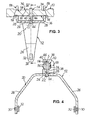
- eine abgebrochene perspektivische Darstellung einer Vorrichtung zur Übertragung von Schaltbewegungen nach einem ersten Ausführungsbeispiel der Erfindung, die eine Schaltgabel mit einteilig damit ausgebildeten Führungsteilen aus Flachmaterial, eine Schaltschiene und einen Schwenkzapfen in der Form eines Bundbolzens aufweist,
- Fig. 2
- eine abgebrochene Draufsicht auf die Vorrichtung gemäß Fig. 1,
- Fig. 3
- eine abgebrochene Schnittansicht der Vorrichtung gemäß Fig. 1 entsprechend der Schnittverlaufslinie III-III in Fig. 2,
- Fig. 4
- eine Schnittansicht der Vorrichtung gemäß Fig. 1 entsprechend der Schnittverlaufslinie IV-IV in Fig. 3,
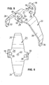
- Fig. 5
- eine perspektivische Darstellung des Grundkörpers der bei der Vorrichtung gemäß Fig. 1 verwendeten Schaltgabel,
- Fig. 6
- eine Draufsicht auf den Schaltgabel-Grundkörper gemäß Fig. 5,
- Fig. 7
- eine Vorderansicht des Schaltgabel-Grundkörpers gemäß Fig. 5,
- Fig. 8
- eine Seitenansicht des Schaltgabel-Grundkörpers gemäß Fig. 5 von links in den Fig. 6 und 7,
- Fig. 9
- eine abgebrochene perspektivische Darstellung einer Vorrichtung zur Übertragung von Schaltbewegungen nach einem zweiten Ausführungsbeispiel der Erfindung, die eine Schaltgabel mit daran formschlüssig angebrachten Führungsteilen aus Flachmaterial, eine Schaltschiene und einen Schwenkzapfen in der Form eines Bundbolzens aufweist,
- Fig. 10
- eine abgebrochene Draufsicht auf die Vorrichtung gemäß Fig. 9,
- Fig. 11
- eine abgebrochene Schnittansicht der Vorrichtung gemäß Fig. 9 entsprechend der Schnittverlaufslinie XI-XI in Fig. 10,
- Fig. 12
- eine Schnittansicht der Vorrichtung gemäß Fig. 9 entsprechend der Schnittverlaufslinie XII-XII in Fig. 11,
- Fig. 13
- eine perspektivische Darstellung des Schaltgabel-Grundkörpers und eines der Führungsteile der Vorrichtung gemäß Fig. 9, die veranschaulicht, wie das Führungsteil formschlüssig an der Schaltgabel angebracht wird,
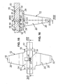
- Fig. 14
- eine abgebrochene perspektivische Darstellung einer Vorrichtung zur Übertragung von Schaltbewegungen nach einem dritten Ausführungsbeispiel der Erfindung, die eine Schaltgabel mit einteilig damit ausgebildeten Führungsteilen aus Flachmaterial, eine Schaltschiene, einen Schwenkzapfen und ein Sicherungselement zum Sichern des Schwenkzapfens an der Schaltschiene aufweist,
- Fig. 15
- eine abgebrochene Draufsicht auf die Vorrichtung gemäß Fig. 14,
- Fig. 16
- eine abgebrochene Schnittansicht der Vorrichtung gemäß Fig. 14 entsprechend der Schnittverlaufslinie XVI-XVI in Fig. 15,
- Fig. 17
- eine Schnittansicht der Vorrichtung gemäß Fig. 14 entsprechend der Schnittverlaufslinie XVII-XVII in Fig. 16,
- Fig. 18
- eine perspektivische Darstellung des Grundkörpers der bei der Vorrichtung gemäß Fig. 14 verwendeten Schaltgabel,
- Fig. 19
- eine Draufsicht auf den Schaltgabel-Grundkörper gemäß Fig. 18,
- Fig. 20
- eine Vorderansicht des Schaltgabel-Grundkörpers gemäß Fig. 18,
- Fig. 21
- eine Seitenansicht des Schaltgabel-Grundkörpers gemäß
Fig. 18 von links in den Fig. 19
und 20, - Fig. 22
- eine im Maßstab vergrößerte, perspektivische Darstellung des bei der Vorrichtung gemäß Fig. 14 verwendeten Sicherungselements,
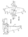
- Fig. 23
- eine abgebrochene perspektivische Darstellung einer Vorrichtung zur Übertragung von Schaltbewegungen nach einem vierten Ausführungsbeispiel der Erfindung, die eine Schaltgabel, eine Schaltschiene, einen Schwenkzapfen in der Form eines Bundbolzens sowie ein an der Schaltschiene befestigtes Führungsteil aus Flachmaterial aufweist,
- Fig. 24
- eine beidseitig abgebrochene Draufsicht auf die Vorrichtung gemäß Fig. 23,
- Fig. 25
- eine beidseitig abgebrochene Schnittansicht der Vorrichtung gemäß Fig. 23 entsprechend der Schnittverlaufslinie XXV-XXV in Fig. 24,
- Fig. 26
- eine Schnittansicht der Vorrichtung gemäß Fig. 23 entsprechend der Schnittverlaufslinie XXVI-XXVI in Fig. 25,
- Fig. 27
- eine perspektivische Darstellung des Grundkörpers der bei der Vorrichtung gemäß Fig. 23 verwendeten Schaltgabel,
- Fig. 28
- eine perspektivische Darstellung des bei der Vorrichtung gemäß Fig. 23 verwendeten Führungsteils,
- Fig. 29
- eine beidseitig abgebrochene Unteransicht der bei der Vorrichtung gemäß Fig. 23 verwendeten Schaltschiene im Lagerbereich für die Schaltgabel,
- Fig. 30
- eine beidseitig abgebrochene Seitenansicht der Schaltschiene gemäß Fig. 29 und
- Fig. 31
- eine beidseitig abgebrochene Draufsicht auf die Schaltschiene gemäß Fig. 29.
- Fig. 1
- a broken perspective view of a device for transmitting switching movements according to a first embodiment of the invention, which has a shift fork with integrally formed therewith guide members made of flat material, a shift rail and a pivot pin in the form of a collar bolt,
- Fig. 2
- a broken plan view of the device of FIG. 1,
- Fig. 3
- 3 is a broken sectional view of the device according to FIG. 1 corresponding to the section line III-III in FIG. 2, FIG.
- Fig. 4
- 1 is a sectional view of the device according to FIG. 1 corresponding to the section line IV-IV in FIG. 3, FIG.
- Fig. 5
- a perspective view of the main body of the shift fork used in the apparatus of FIG. 1,
- Fig. 6
- a top view of the shift fork main body of FIG. 5,
- Fig. 7
- a front view of the shift fork main body of FIG. 5,
- Fig. 8
- 5 is a side view of the shift fork main body according to FIG. 5 from the left in FIGS. 6 and 7,
- Fig. 9
- a broken perspective view of a device for transmitting switching movements according to a second embodiment of the invention, which has a shift fork with form-fitting mounted guide members made of flat material, a shift rail and a pivot pin in the form of a collar bolt,
- Fig. 10
- a broken plan view of the device of FIG. 9,
- Fig. 11
- 9 is a broken sectional view of the device according to FIG. 9 corresponding to the section line XI-XI in FIG. 10, FIG.
- Fig. 12
- 9 shows a sectional view of the device according to FIG. 9 corresponding to the section line XII-XII in FIG. 11,
- Fig. 13
- 9 is a perspective view of the shift fork main body and one of the guide parts of the device according to FIG. 9, which illustrates how the guide part is positively attached to the shift fork,
- Fig. 14
- a broken perspective view of a device for transmitting switching movements according to a third embodiment of the invention, which has a shift fork with integrally formed guide members made of flat material, a shift rail, a pivot pin and a securing element for securing the pivot pin on the shift rail,
- Fig. 15
- a broken plan view of the device of FIG. 14,
- Fig. 16
- FIG. 15 is a fragmentary sectional view of the device according to FIG. 14, corresponding to the section line XVI-XVI in FIG. 15, FIG.
- Fig. 17
- a sectional view of the device according to FIG. 14 corresponding to the section line XVII-XVII in FIG. 16, FIG.
- Fig. 18
- a perspective view of the main body of the shift fork used in the apparatus of FIG. 14,
- Fig. 19
- a top view of the shift fork main body of FIG. 18,
- Fig. 20
- a front view of the shift fork main body of FIG. 18,
- Fig. 21
- a side view of the shift fork main body according to FIG. 18 from the left in FIGS. 19 and 20,
- Fig. 22
- an enlarged scale perspective view of the fuse element used in the apparatus of FIG. 14,
- Fig. 23
- a broken perspective view of a device for transmitting switching movements according to a fourth embodiment of the invention, which has a shift fork, a shift rail, a pivot pin in the form of a collar pin and a mounted on the shift rail guide member made of flat material,
- Fig. 24
- a broken off on both sides plan view of the device according to FIG. 23,
- Fig. 25
- 2 is a broken away sectional view of the device according to FIG. 23 corresponding to the section line XXV-XXV in FIG. 24, FIG.
- Fig. 26
- a sectional view of the device according to FIG. 23 corresponding to the section line XXVI-XXVI in FIG. 25, FIG.
- Fig. 27
- a perspective view of the main body of the shift fork used in the apparatus of FIG. 23,
- Fig. 28
- a perspective view of the guide member used in the apparatus of FIG. 23,
- Fig. 29
- a broken off on both sides bottom view of the shift rail used in the apparatus of FIG. 23 in the storage area for the shift fork,
- Fig. 30
- a broken off on both sides side view of the shift rail of FIG. 29 and
- Fig. 31
- a broken off on both sides plan view of the shift rail of FIG. 29th
Die Fig. 1 bis 8 veranschaulichen ein erstes Ausführungsbeispiel
einer Vorrichtung zur Übertragung von Schaltbewegungen in
einem Kraftfahrzeug-Schaltgetriebe im nicht darin eingebauten
Zustand, die eine Schaltschiene 10 und eine daran auf besondere
Art und Weise schwenkgelagerte Schaltgabel 12 aufweist. Genauer
gesagt sind die Schaltschiene 10 und die Schaltgabel 12 mittels
eines rechtwinklig zur Schaltschienenachse gerichteten Schwenkzapfens
14 in Richtung der Schaltschienenachse, d.h. in Längsrichtung
der Schaltschiene 10 relativ zueinander unverschiebbar
festgelegt, wobei die Schaltgabel 12 durch mindestens zwei
gegenüberliegende zueinander planparallele Führungsflächen 16
gegenüber der Schaltschiene 10 geführt um die Schwenkzapfenachse
S (siehe Fig. 4) um einen geringen Winkelbetrag relativ
zur Schaltschiene 10 verschwenkbar ist. Wesentlich ist, daß,
wie nachfolgend noch näher erläutert werden wird, wenigstens
eine der Führungsflächen 16 an einem Führungsteil 18 aus einem
Flachmaterial ausgebildet ist, welches im dargestellten Ausführungsbeispiel
fest mit der Schaltgabel 12 verbunden ist.Figs. 1 to 8 illustrate a first embodiment
a device for transmitting switching movements in
a motor vehicle transmission in not built into it
Condition, which is a
Wie insbesondere die Fig. 5 bis 8 zeigen, weist die Schaltgabel
12 einen Grundkörper 20 auf, der aus einem metallischen Flachmaterial
hergestellt ist, wobei zwei Führungsteile 18 einteilig
mit dem Grundkörper 20 der Schaltgabel 12 ausgebildet ist. Genauer
gesagt hat der Grundkörper 20 der Schaltgabel 12 eine in
einer Draufsicht gesehen (siehe die Fig. 5 und 6) im wesentlichen
rechteckige, mit einer zentralen Bohrung 22 zur Aufnahme
des Schwenkzapfens 14 versehene, ebene Basis 24 mit zwei Längsseiten
und zwei Querseiten. Von jeder Querseite der Basis 24
erstreckt sich in bilateraler Symmetrie bezüglich einer gedachten,
durch die Längsachse der Bohrung 22 verlaufenden Ebene ein
Schaltgabelarm 26 weg, während sich - in Liniensymmetrie bezüglich
der Mittelachse der Bohrung 22 - an jede Längsseite der
Basis 24 eines der Führungsteile 18 anschließt, die, wie die
Fig. 3 und 7 zeigen, rechtwinklig von der Basis 24 abgebogen
sind. Zur Erleichterung des Biegevorgangs ist hierbei das
Flachmaterial des Schaltgabel-Grundkörpers 20 im Übergangsbereich
von Basis 24 und Führungsteil 18 jeweils mit einer Aussparung
28 versehen. Wie des weiteren in den Fig. 1, 3, 4, 5, 7
und 8 deutlich zu erkennen ist, erstrecken sich die Schaltgabelarme
26 einerseits und die Führungsteile 18 andererseits
in Dickenrichtung der Basis 24 gesehen in entgegengesetzte
Richtungen von der Basis 24 weg. As particularly Figs. 5 to 8 show, the shift fork
12 a
Gemäß insbesondere den Fig. 4 und 8 sind die Schaltgabelarme 26
noch ein zweites Mal abgekröpft, derart, daß ihre freien Enden
bezüglich der Basis 24 rechtwinklig stehen. Die freien Enden
der Schaltgabelarme 26 sind im dargestellten Ausführungsbeispiel
jeweils mit einer Befestigungsbohrung 30 versehen, die
der Befestigung von Eingriffskörpern 32 (vergl. die Fig. 1, 3
und 4) - auch "Padden" genannt - dienen, über welche die
Schaltgabel 12 in an sich bekannter Weise mit der Schalt- bzw.
Schiebemuffe (nicht dargestellt) des Kraftfahrzeug-Schaltgetriebes
wirkverbindbar ist.Referring particularly to FIGS. 4 and 8, the
Jedes Führungsteil 18 ist des weiteren gemäß insbesondere den
Fig. 1, 3 und 4 mit einer Aussparung 34 zur Aufnahme der
Schaltschiene 10 versehen, wobei jede Aussparung 34 ein Paar
planparalleler Führungsflächen 16 aufweist, die ihrerseits
parallel zu der Basis 24 des Grundkörpers 20 verlaufen. Bei dem
in den Fig. 1 bis 8 dargestellten ersten Ausführungsbeispiel
ist die Aussparung 34 jedes Führungsteils 18 als Schlitz ausgebildet,
der sich parallel zur Basis 24 des Schaltgabel-Grundkörpers
20 erstreckt, wobei sich die Schlitze in den Führungsteilen
18 gemäß insbesondere den Fig. 1 und 5 in einer Drehrichtung
um die Achse S des Schwenkzapfens 14 gesehen in die
gleiche Richtung öffnen. Hierbei ist die Tiefe der Schlitze
derart gewählt, daß im montierten Zustand der Vorrichtung zwischen
dem jeweiligen Schlitzende und der Schaltschiene 10 ein
Schwenkspiel vorhanden ist, wie in Fig. 4 zu erkennen ist.Each
Die Schaltschiene 10 ist im dargestellten Ausführungsbeispiel
aus einem metallischen Rundmaterial hergestellt, welches nahe
seinem Ende auf gegenüberliegenden Seiten mit jeweils einer Abflachung
oder Ausnehmung 36 versehen ist, die planparallele
Gegenflächen 38 für die Führungsflächen 16 an den Führungsteilen
18 ausbilden. Hierbei sind die Ausnehmungen 36 z.B. durch
Räumen derart an der Schaltschiene 10 angearbeitet, daß die
Gegenflächen 38 einen Abstand zueinander aufweisen, der bezüglich
des lichten Abstands der Führungsflächen 16 an den Führungsteilen
18 ein geringfügiges Untermaß hat. Schließlich ist
auch die Schaltschiene 10 mittig bezüglich der Ausnehmungen 36
mit einer durchgehenden Bohrung 40 zur Aufnahme des Schwenkzapfens
14 versehen, die senkrecht zur Längsachse der Schaltschiene
10 und zu den Gegenflächen 38 in die Schaltschiene 10
eingebracht ist.The
Bei dem ersten Ausführungsbeispiel der Vorrichtung ist gemäß
den Fig. 3 und 4 schließlich der metallische Schwenkzapfen 14
in einem mittleren Bereich mit einem Bund 42 versehen. Dabei
erstreckt sich der Schwenkzapfen 14 auf der einen Seite des
Bundes 42 mit einem kürzeren Ende 44 in die zentrale Bohrung 22
in der Basis 24 des Schaltgabel-Grundkörpers 20 hinein, während
der Schwenkzapfen 14 auf der anderen Seite des Bundes 42 mit
seinem anderen, längeren Ende 46 in die Bohrung 40 in der
Schaltschiene 10 eingesetzt ist. Die Länge des Bundes 42 ist
hierbei so bemessen, daß sie geringfügig kürzer ist als der
lichte Abstand zwischen der in den Fig. 3 und 4 oberen Hauptfläche
der Basis 24 des Schaltgabel-Grundkörpers 20 und der
dieser zugewandten Gegenfläche 38 an der entsprechenden Ausnehmung
36 der Schaltschiene 10. Da der Bund 42 des Schwenkzapfens
14 einen Außendurchmesser aufweist, der größer ist als der
Innendurchmesser der Bohrungen 22, 40 in der Schaltgabel 12
bzw. der Schaltschiene 10, ist der auf beiden Seiten geringfügig
über die Bohrungen 22, 40 vorstehende Schwenkzapfen 14 an
der Vorrichtung verliersicher festgelegt.In the first embodiment of the device is according to
3 and 4, finally, the metallic pivot pin 14th
provided in a central region with a
Zur Herstellung der Vorrichtung werden zunächst die Schaltschiene
10, der Grundkörper 20 der Schaltgabel 12 und der
Schwenkzapfen 14 vorgefertigt. Hierbei werden nach Ablängen der
Schaltschiene 10 die Ausnehmungen 36 an der Schaltschiene 10
z.B. durch Räumen erzeugt, so daß die Gegenflächen 38 an der
Schaltschiene 10 einen definierten Abstand zueinander haben. For the preparation of the device, first, the
Der Grundkörper 20 der Schaltgabel 12 wird - z.B. durch Feinschneiden
aus einem Flachmaterial - zunächst als Flachteil mit
seiner Basis 24, den Führungsteilen 18 und den Schaltgabelarmen
26 hergestellt, wobei zugleich die Aussparungen 28, 34 und ggf.
die Befestigungsbohrungen 30 für die Eingriffskörper 32 erzeugt
werden, bevor die Führungsteile 18 und die Schaltgabelarme 26
wie in Fig. 5 gezeigt definiert von der Basis 24 abgebogen werden.
Bei dem Feinschneidvorgang ergibt sich bereits ein definierter
Abstand der im wesentlichen rechtwinklig bezüglich der
Hauptflächen des Grundkörpers 20 verlaufenden Führungsflächen
16 an der jeweiligen Aussparung 34. Der Schwenkzapfen 14 wird
z.B. in einem Drehautomaten mit definierten Abmessungen seines
Bundes 42 und der Enden 44, 46 fertigbearbeitet.The
Zur Vormontage der Vorrichtung wird zunächst die Schaltschiene
10 zwischen die Führungsteile 18 des Schaltgabel-Grundkörpers
20 gesetzt. Sodann werden Schaltschiene 10 und Grundkörper 20
relativ zueinander verdreht, so daß die Führungsflächen 16 an
den Aussparungen 34 des Grundkörpers 20 über die Gegenflächen
38 an den Ausnehmungen 36 der Schaltschiene 10 gleiten. In der
Folge werden die Schaltschiene 10 und der Grundkörper 20 ausgerichtet
und in zueinander genau justierter Lage festgelegt,
worauf die Schaltschiene 10 und der Grundkörper 20 in dieser
festgelegten Relativlage zur Bildung der durchmessergleichen
Aufnahmebohrungen 22, 40 für den Schwenkzapfen 14 in einem
Bohrvorgang gemeinsam gebohrt werden. Nach dem Bohrvorgang werden
Schaltschiene 10 und Grundkörper 20 voneinander getrennt.
Sodann wird die Schaltschiene 10 unter Zwischenfügung des
Schwenkzapfens 14 wieder zwischen die Führungsteile 18 des
Grundkörpers 20 gesetzt, wobei der Schwenkzapfen 14 mit seinen
Enden 44 und 46 in die Bohrungen 22 bzw. 40 gleitet. Durch Verdrehen
der Schaltschiene 10 relativ zum Grundkörper 20 um die
Achse S des Schwenkzapfens 14 gelangen schließlich die Führungsflächen
16 an den Aussparungen 34 des Grundkörpers 20
wieder über die zugeordneten Gegenflächen 38 an den Ausnehmungen
36 der Schaltschiene 10. Nach Befestigen der Eingriffskörper
32 in den Befestigungsbohrungen 30 an den Schaltgabelarmen
26 kann jetzt die vormontierte Vorrichtung im Kraftfahrzeug-Schaltgetriebe
in an sich bekannter Weise fertigmontiert werden.For pre-assembly of the device is initially the
Im folgenden soll das zweite Ausführungsbeispiel der Vorrichtung unter Bezugnahme auf die Fig. 9 bis 13 nur insoweit beschrieben werden, als es sich von dem unter Bezugnahme auf die Fig. 1 bis 8 beschriebenen ersten Ausführungsbeispiel wesentlich unterscheidet.In the following, the second embodiment of the device with reference to Figs. 9 to 13 described only insofar be, as it is from the reference to the Fig. 1 to 8 described the first embodiment substantially different.
Auch bei dem zweiten Ausführungsbeispiel weist die Schaltgabel
12 einen Grundkörper 20 auf, der aus einem metallischen Flachmaterial
besteht. Die Führungsteile 18 jedoch werden als zunächst
vom Grundkörper 20 separate Teile aus einem metallischen
Flachmaterial hergestellt, welches sich von dem Flachmaterial
des Grundkörpers 20 unterscheiden kann aber nicht muß, bevor
die Führungsteile 18 form- und ggf. kraftschlüssig mit dem
Grundkörper 20 verbunden werden. Genauer gesagt hat der Grundkörper
20 der Schaltgabel 12 gemäß insbesondere der Fig. 13
eine in einer Draufsicht gesehen im wesentlichen rechteckige
Basis 24 mit zwei Längsseiten und zwei Querseiten, wobei sich
von jeder Querseite ein Schaltgabelarm 26 wegerstreckt. An jede
Längsseite der Basis 24 indes schließen sich wenigstens ein, im
dargestellten Ausführungsbeispiel zwei Vorsprünge 48 mit im
wesentlichen rechteckigen Querschnitt an, die dazu im wesentlichen
komplementär geformte Öffnungen 50 in dem der jeweiligen
Längsseite der Basis 24 zugeordneten Führungsteil 18 durchgreifen
und mit letzterem warmvernietet sind, so daß das jeweilige
Führungsteil 18 fest mit der Basis 24 des Grundkörpers 20 verbunden
ist und mit diesem einen rechten Winkel einschließt. Der
so erzielten Formschlußverbindung zwischen der Basis 24 und den
Führungsteilen 18 kann ein zusätzlicher Kraftschluß überlagert
sein, der durch ein Übermaß des jeweiligen Vorsprungs 48 an der
Basis 24 bezüglich der zugeordneten Öffnung 50 im jeweiligen
Führungsteil 18 bewirkt wird, so daß die Führungsteile 18 schon
vor dem Warmvernieten in der Art eines Preßsitzes an der Basis
24 festgelegt sind.Also in the second embodiment, the shift fork
12 a
Die Herstellung bzw. Montage der Vorrichtung nach dem zweiten
Ausführungsbeispiel unterscheidet sich von dem zum ersten Ausführungsbeispiel
beschriebenen Verfahren nur hinsichtlich der
Vorfertigung des Verbunds aus dem Schaltgabel-Grundkörper 20
und den Führungsteilen 18. Hierbei werden der Grundkörper 20
der Schaltgabel 12 mit seiner Basis 24, den Schaltgabelarmen 26
und den Vorsprüngen 48 einerseits und die Führungsteile 18
andererseits z.B. durch Feinschneiden als Flachteile hergestellt,
wobei zugleich die Aussparungen 34 und Öffnungen 50 in
den Führungsteilen 18 sowie ggf. die Befestigungsbohrungen 30
für die Eingriffskörper 32 an den Schaltgabelarmen 26 erzeugt
werden. Sodann werden die Schaltgabelarme 26 definiert von der
Basis 24 des Grundkörpers 20 abgebogen, worauf die Führungsteile
18 wie in Fig. 13 mit gestrichelten Linien angedeutet mit
ihren Öffnungen 50 auf die Vorsprünge 48 an der Grundkörperbasis
24 aufgeschoben werden. Schließlich werden die über die
Öffnungen 50 vorstehenden Enden der Vorsprünge 48 warmvernietet,
um die Führungsteile 18 am Schaltgabel-Grundkörper 20 zu
befestigen.The manufacture or assembly of the device according to the second
Embodiment differs from that of the first embodiment
described method only in terms of
Prefabrication of the composite of the shift fork
Auch das dritte Ausführungsbeispiel der Vorrichtung soll nachfolgend anhand der Fig. 14 bis 22 nur insoweit beschrieben werden, als es sich vom ersten und zweiten Ausführungsbeispiel wesentlich unterscheidet.Also, the third embodiment of the device is intended below be described only with reference to FIGS. 14 to 22, as it is from the first and second embodiments essentially different.
Um eine Montage der Einzelteile der Vorrichtung noch im Kraftfahrzeug-Schaltgetriebe
zu gestatten, sind bei dem dritten Ausführungsbeispiel
der lichte Abstand der Führungsflächen 16 an
den Aussparungen 34 der Führungsteile 18 einerseits und die Abmessungen
der Schaltschiene 10 in einer Richtung senkrecht zur
Schaltschienenachse andererseits derart aufeinander abgestimmt,
daß die Schaltschiene 10 in Richtung der Schaltschienenachse in
die Aussparungen 34 der Führungsteils 18 einführbar ist bevor
die Schaltgabel 12 mittels des Schwenkzapfens 14 an der Schaltschiene
10 montiert wird.To an assembly of the items of the device still in the motor vehicle manual transmission
to allow are in the third embodiment
the clear distance of the guide surfaces 16 at
the
Hierbei hat gemäß Fig. 14 der die Schaltgabel 12 tragende Abschnitt
der Schaltschiene 10 einen durchgehend kreisrunden
Querschnitt - ohne Ausnehmungen wie bei den vorbeschriebenen
Ausführungsbeispielen - mit einem Außendurchmesser, der geringfügig
kleiner ist als der lichte Abstand der Führungsflächen 16
an den Aussparungen 34 in den Führungsteilen 18. Die Bohrung 40
zur Aufnahme des Schwenkzapfens 14 ist dabei so in die Schaltschiene
10 eingebracht, daß sie die Längsachse der Schaltschiene
10 im rechten Winkel schneidet.Here, as shown in FIG. 14, the
Wie insbesondere in den Fig. 18 bis 21 zu erkennen ist, unterscheidet
sich der Grundkörper 20 der Schaltgabel 12 bei dem
dritten Ausführungsbeispiel von dem Grundkörper bei dem ersten
Ausführungsbeispiel im wesentlichen dadurch, daß auch die Führungsteile
18 in bilateraler Symmetrie bezüglich einer gedachten
Ebene von der Grundkörperbasis 24 abgebogen sind, welche
die Mittelachse der Bohrung 22 in der Basis 24 enthält, und daß
die Aussparungen 34 in den Führungsteilen 18 eine umfänglich
geschlossene Form haben, genauer gesagt als zur ebenen Basis 24
parallel verlaufende Langlöcher ausgebildet sind.As can be seen in particular in FIGS. 18 to 21, differs
the
Im Gegensatz zu den vorbeschriebenen Ausführungsbeispielen ist
ferner der Schwenkzapfen 14 mittels eines separaten Sicherungselements
in der Form eines in Fig. 22 vergrößert dargestellten
Federclips 52 aus vorzugsweise Federstahl an der Schaltschiene
10 verliersicher festgelegt. Der Federclip 52 ist in einer Seitenansicht
gesehen (vergl. Fig. 17) im wesentlichen C-förmig,
mit einem ersten Ende, das eine kreisrunde Öffnung 54 aufweist,
deren Innendurchmesser geringfügig größer ist als der Außendurchmesser
des Schwenkzapfens 14, und einem zweiten Ende, welches
mit einem Schlitz 56, dessen lichte Breite geringfügig
kleiner ist als der Außendurchmesser des Schwenkzapfens 14, und
zu beiden Seiten des Schlitzes 56 mit nach innen abgekröpften
Nasen 58 versehen ist. Der zylindrische Schwenkzapfen 14 hingegen
weist in einem mittleren Bereich eine Radialnut 60 auf,
die etwas breiter ist als der Federclip 52 dick und deren Nutgrund
einen Durchmesser hat, der geringfügig kleiner ist als
die lichte Breite des Schlitzes 56 im Federclip 52. Wie die
Fig. 14 bis 17 zeigen, greift der Federclip 52 im Bereich seines
Schlitzes 56 mit einem Ende in die Radialnut 60 am Schwenkzapfen
14 ein und umgreift die Schaltschiene 10, wobei sich das
in den Fig. 14, 16 und 17 obere Ende 46 des Schwenkzapfens 14,
welches geringfügig über die Bohrung 40 in der Schaltschiene 10
übersteht, durch die Öffnung 54 am anderen Ende des Federclips
52 hindurch erstreckt. Es ist ersichtlich, daß der Federclip 52
somit den Schwenkzapfen 14 unverlierbar aber bei Bedarf lösbar
an der Schaltschiene 10 festlegt.In contrast to the above-described embodiments
further, the
Zur Herstellung der Vorrichtung gemäß dem dritten Ausführungsbeispiel
werden zunächst die Schaltschiene 10, der Grundkörper
20 der Schaltgabel 12, der Schwenkzapfen 14 und der Federclip
52 vorgefertigt, wobei die Schaltschiene 10 lediglich von einem
Rundmaterial abzulängen ist, der Grundkörper 20 der Schaltgabel
12 wie anhand des ersten Ausführungsbeispiels beschrieben aus
einem Flachmaterial ausgebildet wird und der Schwenkzapfen 14
etwa in einem Drehautomaten mit der Radialnut 60 zu versehen
ist. Die Fertigung des Federclips 52 bedarf für den Fachmann
keiner näheren Erläuterung.For producing the device according to the third embodiment
First, the
Sodann werden die Bohrungen 22 und 40 in der Basis 24 des
Schaltgabel-Grundkörpers 20 bzw. der Schaltschiene 10 gemeinsam
gebohrt. Hierzu wird die Schaltschiene 10 in Richtung ihrer
Längsachse durch die Aussparungen 34 in den Führungsteilen 18
der Schaltgabel 12 hindurch gesteckt. In der Folge werden die
Schaltschiene 10 und die Schaltgabel 12 ausgerichtet und in
zueinander genau justierter Lage festgelegt, wonach die Schaltschiene
10 und die Schaltgabel 12 in dieser festgelegten Relativlage
zur Bildung der durchmessergleichen Aufnahmebohrungen
22, 40 für den Schwenkzapfen 14 in einem Bohrvorgang mit einem
Bohrer gemeinsam gebohrt werden. Sodann werden Schaltschiene 10
und Schaltgabel 12 wieder voneinander getrennt. Für den Fachmann
ist ersichtlich, daß die Montage der Vorrichtung im Kraftfahrzeug-Schaltgetriebe
jetzt vornehmlich in axialer Richtung
der Schaltschiene 10 erfolgen kann, indem diese bezüglich der
Schaltgabel 12 geeignet winkelpositioniert soweit in die Aussparungen
34 in den Führungsteilen 18 der Schaltgabel 12 hinein
gesteckt wird bis die Bohrungen 22, 40 in Schaltschiene 10 und
Schaltgabel 12 ausgefluchtet sind. Danach kann der Schwenkzapfen
14 in Querrichtung zur Schaltschiene 10 in die Bohrungen
22, 40 eingefügt und durch Queraufschieben des aufgefederten
oder auffedernden Federclips 52 an der Schaltschiene 10 gesichert
werden, wobei der Federclip 52 im Bereich seines
Schlitzes 56 über die Radialnut 60 im Schwenkzapfen 14 geschoben
wird und mit seiner Öffnung 54 an dem in den Fig. 14,
16 und 17 oberen Ende 46 des Schwenkzapfens 14 verrastet.Then, the
Obgleich bei dem unter Bezugnahme auf die Fig. 14 bis 22 beschriebenen
dritten Ausführungsbeispiel der Vorrichtung die
Führungsteile 18 einteilig mit dem Grundkörper 20 der Schaltgabel
12 ausgebildet sind, kann es sich hier bei den Führungsteilen
auch um zunächst vom Grundkörper der Schaltgabel getrennt
hergestellte Führungsteile handeln, die analog dem unter
Bezugnahme auf die Fig. 9 bis 13 beschriebenen zweiten Ausführungsbeispiel
der Vorrichtung sodann form- und ggf. kraftschlüssig
- etwa mittels Warmvernieten entsprechender Vorsprünge
an den Führungsteilen oder dem Grundkörper, die Öffnungen
in dem jeweils anderen Teil durchgreifen - mit dem
Schaltgabel-Grundkörper verbunden werden. Although described with reference to Figs
third embodiment of the device the
Den Fig. 23 bis 31 ist schließlich ein viertes Ausführungsbeispiel
der Vorrichtung zu entnehmen, welches sich von den vorbeschriebenen
Ausführungsbeispielen im wesentlichen dadurch
unterscheidet, daß ein mit der Schaltschiene 10 fest verbundenes
Führungsteil 18 aus einem Flachmaterial eine der Führungsflächen
16 für die Schaltgabel 12 ausbildet.Finally, FIGS. 23 to 31 show a fourth exemplary embodiment
to remove the device, which differs from the above
Embodiments essentially thereby
differs that one firmly connected to the
Wie insbesondere die Fig. 23, 25 und 28 zeigen, handelt es sich
bei dem Führungsteil 18 der Vorrichtung gemäß dem vierten Ausführungsbeispiel
um einen an der Schaltschiene 10 befestigten,
ebenen Blechstreifen mit zwei planparallelen Hauptflächen.
Gemäß insbesondere der Fig. 25 bildet die in dieser Fig. obere
Hauptfläche des Führungsteils 18 eine der Führungsflächen 16
für die Schaltgabel 12 aus, während die Schaltschiene 10 mit
einer gestuften, beispielsweise geräumten Ausnehmung 62 versehen
ist, welche die andere, in der Fig. 25 obere Führungsfläche
16 ausbildet. Auch bei diesem Ausführungsbeispiel weist
die Schaltgabel 12 einen aus einem Flachmaterial hergestellten
Grundkörper 20 auf, der im Bereich seiner ebenen Basis 24 mit
geringfügigem Bewegungsspiel zwischen der Führungsfläche 16 an
der Ausnehmung 62 der Schaltschiene 10 und der Führungsfläche
16 am Führungsteil 18 aufgenommen ist.As particularly shown in FIGS. 23, 25 and 28, it is
in the
Insbesondere den Fig. 29 und 30 sind Einzelheiten der gestuften
Ausnehmung 62 an der Schaltschiene 10 zu entnehmen. Demgemäß
hat die Ausnehmung 62 in bilateraler Symmetrie zu beiden Seiten
der Führungsfläche 16 eine zu letzterer parallele Auflagerfläche
64 für das Führungsteil 18, wobei jede Auflagerfläche 64 in
einer Richtung senkrecht zur Führungsfläche 16 von letzterer um
einen Betrag beabstandet ist, der geringfügig größer ist als
die Dicke des Schaltgabel-Grundkörpers 20 im Bereich der Basis
24. Ausgehend von jeder Auflagerfläche 64 ist eine durchgehende
Befestigungsbohrung 66 senkrecht zur Schaltschienenachse in die
Schaltschiene 10 eingebracht, die der Aufnahme eines Befestigungselements,
im dargestellten Ausführungsbeispiel eines Niets
68 dient. An ihrem von der Auflagerfläche 64 abgewandten Ende
ist jede Befestigungsbohrung 66 mit einer Kegelabsenkung 70
versehen, in der, wie die Fig. 25 zeigt, ein komplementär geformter
Nietkopf 72 des jeweiligen Niets 68 aufgenommen ist.
Mittig zwischen den Auflagerflächen 64 ist die Ausnehmung 62 in
der Schaltschiene 10 an der Führungsfläche 16 schließlich noch
mit einer Vertiefung 74 zur Aufnahme des Bunds 42 am Schwenkzapfen
14 (siehe die Fig. 25 und 26) versehen, deren Tiefe geringfügig
größer ist als die Breite des Bunds 42 in Längsrichtung
des Schwenkzapfens 14.In particular, Figs. 29 and 30 are details of the stepped ones
Recess 62 can be seen on the
Gemäß insbesondere Fig. 28 ist auch der das Führungsteil 18
ausbildende Blechstreifen an beiden Längsenden mit jeweils
einer durchgehenden Befestigungsbohrung 76 versehen, die hinsichtlich
Abstand und Innendurchmesser den Befestigungsbohrungen
66 in der Schaltschiene 10 entsprechen. Schließlich weist
das Führungsteil 18 mittig zwischen den Befestigungsbohrungen
66 noch eine durchgehende Bohrung 78 zur Aufnahme des Endes 44
des Schwenkzapfens 14 auf.According to FIG. 28 in particular, the guide part is also the 18
forming sheet metal strips at both longitudinal ends with each
a continuous mounting
Aus Fig. 25 ist ersichtlich, daß, um das Führungsteil 18 an der
Schaltschiene 10 zu befestigen, das Führungsteil 18 derart auf
die Auflagerflächen 64 an der Ausnehmung 62 der Schaltschiene
10 aufgelegt wird, daß die Befestigungsbohrungen 76 im Führungsteil
18 mit den Befestigungsbohrungen 66 in der Schaltschiene
10 fluchten. Nun können die noch unverformten Niete 68
ausgehend von den Kegelabsenkungen 70 in die Befestigungsbohrungen
66, 76 eingefügt werden, so daß die Niete 68 die Befestigungsbohrungen
66, 76 durchgreifen. Bei Anlage der Nietköpfe
72 an den Kegelabsenkungen 70 werden schließlich die über
die Befestigungsbohrungen 76 im Führungsteil 18 vorstehenden
Enden der Niete 68 gegen die von der Führungsfläche 16 abgewandte
Hauptfläche des Führungsteils 18 warmvernietet, um letzteres
an der Schaltschiene 10 festzulegen. From Fig. 25 it is seen that, to the
Die Fig. 25 und 26 zeigen auch, daß im montierten Zustand der
Vorrichtung der in einem mittleren Bereich mit dem Bund 42 versehene
Schwenkzapfen 14 sich auf der einen Seite des Bundes 42
mit seinem in den Fig. unteren Ende 44 durch die Lagerbohrung
22 in der Basis 24 des Schaltgabel-Grundkörpers 20 hindurch in
die zentrale Bohrung 78 im Führungsteil 18 hinein erstreckt,
während der Schwenkzapfen 14 auf der anderen Seite des Bundes
42 mit seinem in den Fig. oberen Ende 46 die Bohrung 40 in der
Vertiefung 74 der Schaltschienen-Ausnehmung 62 durchgreift. Im
Ergebnis ist der Schwenkzapfen 14 über den Bund 42 verliersicher
an der Vorrichtung gehalten.Figs. 25 and 26 also show that in the assembled state of
Device provided in a central region with the
Die Vorfertigung des Schwenkzapfens 14 und des Grundkörpers 20
der Schaltgabel 12 erfolgt analog der oben beschriebenen Vorgehensweise.
Auch der das Führungsteil 18 ausbildende Blechstreifen
kann aus dem Flachmaterial durch Feinschneiden hergestellt
werden, wobei zugleich die endseitigen Befestigungsbohrungen
76 erzeugt werden. Zur Vorfertigung der Schaltschiene 10
wird die Ausnehmung 62 unter Ausbildung der Führungsfläche 16,
der Auflagerflächen 64 und der Vertiefung 74 z.B. geräumt. In
Folgeschritten werden die Befestigungsbohrungen 66 und die
Kegelabsenkungen 70 ausgebildet.The prefabrication of the
Zur Vormontage der Vorrichtung werden die Schaltschiene 10, die
Schaltgabel 12 und der das Führungsteil 18 ausbildende Blechstreifen
sandwichartig übereinandergelegt. Hierbei erfolgt eine
Ausrichtung des Führungsteils 18 bezüglich der Schaltschiene 10
durch z.B. Stifte (nicht gezeigt) einer Montagevorrichtung, die
in die Befestigungsbohrungen 66, 76 in Schaltschiene 10 und
Führungsteil 18 eingreifen. In der Folge werden die Schaltschiene
10 und der Grundkörper 20 ausgerichtet und in zueinander
genau justierter Lage festgelegt, worauf das Führungsteil
18, der Grundkörper 20 und die Schaltschiene 10 in dieser festgelegten
Relativlage zur Bildung der durchmessergleichen Aufnahmebohrungen
78, 22 und 40 für den Schwenkzapfen 14 in einem
Bohrvorgang mit einem Bohrer gemeinsam gebohrt werden. Nach dem
Bohrvorgang werden die gesandwichten Einzelteile wieder auseinandergenommen,
der Schwenkzapfen 14 wird wie in den Fig. 25
und 26 gezeigt zwischen Schaltschiene 10 und Schaltgabel 12
eingefügt und das über das Ende 44 des Schwenkzapfens 14 gesetzte
Führungsteil 18 wird schließlich wie oben bereits beschrieben
mit der Schaltschiene 10 unter Zuhilfenahme der Niete
68 warmvernietet. Die dergestalt vormontierte Vorrichtung kann
jetzt im Kraftfahrzeug-Schaltgetriebe in an sich bekannter
Weise fertigmontiert werden.For pre-assembly of the device, the
Wenngleich bei den vorbeschriebenen Ausführungsbeispielen die
Schaltschiene 10 jeweils aus einem Rundmaterial ausgebildet
ist, ist es für den Fachmann ersichtlich, daß die Schaltschiene
den jeweiligen Funktions- und Einbauerfordernissen entsprechend
auch aus einem Flachmaterial hergestellt werden kann.Although in the above embodiments, the
Es wird eine Vorrichtung zur Übertragung von Schaltbewegungen in einem Kraftfahrzeug-Schaltgetriebe offenbart, die eine Schaltgabel und eine Schaltschiene aufweist, welche mittels eines rechtwinklig zur Schaltschienenachse gerichteten Schwenkzapfens in Richtung der Schaltschienenachse relativ zueinander unverschiebbar festgelegt sind, wobei die Schaltgabel durch mindestens zwei gegenüberliegende, zueinander planparallele Führungsflächen gegenüber der Schaltschiene geführt um die Schwenkzapfenachse um einen geringen Winkelbetrag relativ zur Schaltschiene verschwenkbar ist, um eine Übertragung von Schwingungen in das Schaltgestänge zu vermeiden. Erfindungsgemäß ist wenigstens eine der Führungsflächen an einem Führungsteil aus einem Flachmaterial ausgebildet, welches fest mit der Schaltgabel oder, alternativ dazu, mit der Schaltschiene verbunden ist. Im Ergebnis wird eine gemessen am Stand der Technik insbesondere in der Massenfertigung kostengünstiger herstellbare Vorrichtung geschaffen, bei der die Schaltgabel gleichwohl toleranzarm an der Schaltschiene schwenkgelagert ist. It is a device for transmitting switching movements disclosed in a motor vehicle manual transmission, the one Has shift fork and a shift rail, which means a right angle to the shift rail axis pivot pin in the direction of the shift rail axis relative to each other are fixed immovably, the shift fork through at least two opposite, plane-parallel Guide surfaces against the shift rail guided around the Pivot pin axis by a small angular amount relative to Switching rail is pivotal to a transmission of Avoid vibrations in the shift linkage. According to the invention is at least one of the guide surfaces on a guide part formed of a flat material, which firmly with the Shift fork or, alternatively, connected to the shift rail is. As a result, one measured by the prior art especially in mass production cost-effectively manufacturable Device created in which the shift fork nevertheless low-tolerance on the shift rail is pivotally mounted.
- 1010
- Schaltschieneshift rail
- 1212
- Schaltgabelshift fork
- 1414
- Schwenkzapfenpivot pin
- 1616
- Führungsflächeguide surface
- 1818
- Führungsteilguide part
- 2020
- Grundkörperbody
- 2222
- Bohrungdrilling
- 2424
- BasisBase
- 2626
- SchaltgabelarmSchaltgabelarm
- 2828
- Aussparungrecess
- 3030
- Befestigungsbohrungmounting hole
- 3232
- Eingriffskörperengaging body
- 3434
- Aussparungrecess
- 3636
- Ausnehmungrecess
- 3838
- Gegenflächecounter surface
- 4040
- Bohrungdrilling
- 4242
- BundFederation
- 4444
- EndeThe End
- 4646
- EndeThe End
- 4848
- Vorsprunghead Start
- 5050
- Öffnungopening
- 5252
- Federclipspring clip
- 5454
- Öffnungopening
- 5656
- Schlitzslot
- 5858
- Nasenose
- 6060
- Radialnutradial groove
- 6262
- Ausnehmungrecess
- 6464
- Auflagerflächebearing surface
- 6666
- Befestigungsbohrungmounting hole
- 6868
- Nietrivet
- 7070
- Kegelabsenkungcone reduction
- 7272
- Nietkopfrivet head
- 7474
- Vertiefung deepening
- 7676
- Befestigungsbohrungmounting hole
- 7878
- Bohrungdrilling
- SS
- SchwenkzapfenachsePivot axis
Claims (16)
Applications Claiming Priority (2)
| Application Number | Priority Date | Filing Date | Title |
|---|---|---|---|
| DE102004027201A DE102004027201B4 (en) | 2004-06-03 | 2004-06-03 | Device for transmitting switching movements in a motor vehicle manual transmission |
| DE102004027201 | 2004-06-03 |
Publications (3)
| Publication Number | Publication Date |
|---|---|
| EP1602862A2 true EP1602862A2 (en) | 2005-12-07 |
| EP1602862A3 EP1602862A3 (en) | 2006-07-19 |
| EP1602862B1 EP1602862B1 (en) | 2008-03-19 |
Family
ID=34937206
Family Applications (1)
| Application Number | Title | Priority Date | Filing Date |
|---|---|---|---|
| EP05011984A Not-in-force EP1602862B1 (en) | 2004-06-03 | 2005-06-03 | Device for conveying shift movement in a gearbox for vehicle |
Country Status (4)
| Country | Link |
|---|---|
| EP (1) | EP1602862B1 (en) |
| AT (1) | ATE389836T1 (en) |
| DE (2) | DE102004027201B4 (en) |
| ES (1) | ES2303974T3 (en) |
Cited By (1)
| Publication number | Priority date | Publication date | Assignee | Title |
|---|---|---|---|---|
| WO2007074030A1 (en) * | 2005-12-24 | 2007-07-05 | Schaeffler Kg | Shift arrangement having a shift fork |
Families Citing this family (2)
| Publication number | Priority date | Publication date | Assignee | Title |
|---|---|---|---|---|
| DE102010014271A1 (en) | 2010-04-08 | 2011-10-13 | Hofer-Pdc Gmbh | Internal circuit for manual transmission, particularly motor vehicle, has shift fork and shift rail, which stand in interference with each other for switching movement transmission |
| AT509997B1 (en) | 2010-08-27 | 2012-01-15 | Stiwa Holding Gmbh | SWITCHING DEVICE FOR A GEAR CHANGING GEAR |
Citations (1)
| Publication number | Priority date | Publication date | Assignee | Title |
|---|---|---|---|---|
| EP1079154A2 (en) | 1999-08-27 | 2001-02-28 | SELZER FERTIGUNGSTECHNIK GMBH & CO. | Selecting shaft with attached shifting fork for a vehicle transmission |
Family Cites Families (3)
| Publication number | Priority date | Publication date | Assignee | Title |
|---|---|---|---|---|
| DE10126438A1 (en) * | 2001-05-31 | 2002-12-12 | Ina Schaeffler Kg | Shift rail with a shift fork |
| DE10159441B4 (en) * | 2001-12-04 | 2011-06-16 | Schaeffler Technologies Gmbh & Co. Kg | Shift fork on a relative to a change gear sliding shift rail |
| DE10220062A1 (en) * | 2002-05-04 | 2003-11-20 | Ina Schaeffler Kg | Attachment of a shift fork |
-
2004
- 2004-06-03 DE DE102004027201A patent/DE102004027201B4/en not_active Expired - Fee Related
-
2005
- 2005-06-03 EP EP05011984A patent/EP1602862B1/en not_active Not-in-force
- 2005-06-03 ES ES05011984T patent/ES2303974T3/en active Active
- 2005-06-03 DE DE502005003270T patent/DE502005003270D1/en active Active
- 2005-06-03 AT AT05011984T patent/ATE389836T1/en not_active IP Right Cessation
Patent Citations (1)
| Publication number | Priority date | Publication date | Assignee | Title |
|---|---|---|---|---|
| EP1079154A2 (en) | 1999-08-27 | 2001-02-28 | SELZER FERTIGUNGSTECHNIK GMBH & CO. | Selecting shaft with attached shifting fork for a vehicle transmission |
Cited By (3)
| Publication number | Priority date | Publication date | Assignee | Title |
|---|---|---|---|---|
| WO2007074030A1 (en) * | 2005-12-24 | 2007-07-05 | Schaeffler Kg | Shift arrangement having a shift fork |
| DE102005062248A1 (en) * | 2005-12-24 | 2007-07-05 | Schaeffler Kg | Automotive gearshift fork assembly has U-shaped sheet metal section with three apertures |
| CN101346570B (en) * | 2005-12-24 | 2011-11-16 | 谢夫勒科技有限两合公司 | Shift arrangement having a shift fork |
Also Published As
| Publication number | Publication date |
|---|---|
| DE502005003270D1 (en) | 2008-04-30 |
| ES2303974T3 (en) | 2008-09-01 |
| DE102004027201A1 (en) | 2005-12-29 |
| ATE389836T1 (en) | 2008-04-15 |
| EP1602862A3 (en) | 2006-07-19 |
| EP1602862B1 (en) | 2008-03-19 |
| DE102004027201B4 (en) | 2006-12-21 |
Similar Documents
| Publication | Publication Date | Title |
|---|---|---|
| DE19580804C1 (en) | Locking sleeve for securing adjustment positions of an actuating element, in particular a shift linkage for motor vehicles | |
| DE202005015034U1 (en) | Slider for a fitting | |
| EP2606766A1 (en) | Pull-out guide for drawers, with a catch hook | |
| EP2730456B1 (en) | Drive for a seat adjusting device for motor vehicles | |
| DE102019127546A1 (en) | Planet carrier with rivets made from carrier halves and manufacturing processes for riveted connections | |
| EP2288826B1 (en) | Method for producing a shift finger arrangement | |
| DE102008029264A1 (en) | Assembly and transport safety arrangement for a switching mechanism of a transmission | |
| DE102008024154B4 (en) | Safety catch of a vehicle lock and lock arrangement | |
| EP1297994A1 (en) | Hinge for a vehicle seat | |
| EP1602862B1 (en) | Device for conveying shift movement in a gearbox for vehicle | |
| DE102014217396B4 (en) | Load-optimized asymmetric planet carrier design | |
| EP1612459B1 (en) | Shift movement transmitting device in a vehicle transmission and method of manufacturing such a device | |
| DE4340410C2 (en) | Surface drainage device | |
| DE102016205977A1 (en) | Assembly for a synchronization device and synchronization device with the module | |
| EP0384158B1 (en) | Rocker fork for motor vehicle shift transmissions | |
| DE102004001593B3 (en) | Production process for fixing element of vehicle seat adjuster involves first step of forging defined length of wire into blank, and second step of producing final outer contour | |
| AT510673B1 (en) | SWITCHING ELEMENT AND METHOD FOR THE PRODUCTION THEREOF AND SWITCHING DEVICE | |
| AT510576B1 (en) | BEARING UNIT FOR A SWITCHING DEVICE OF A MOTOR VEHICLE GEARBOX | |
| DE19705709B4 (en) | Anchoring unit for fastening pipes or similar objects | |
| EP2334957A1 (en) | Shift arrangement for a manual transmission | |
| EP1746312B1 (en) | Actuating device for an selector sleeve | |
| DE10046724B4 (en) | Storage compartment built into a motor vehicle | |
| DE102007036103A1 (en) | Transmission component and method for producing the transmission component | |
| DE19818916C2 (en) | A connection between components | |
| DE202009005552U1 (en) | Forming tool for producing an inner profile, in particular an internal toothing of a workpiece |
Legal Events
| Date | Code | Title | Description |
|---|---|---|---|
| PUAI | Public reference made under article 153(3) epc to a published international application that has entered the european phase |
Free format text: ORIGINAL CODE: 0009012 |
|
| AK | Designated contracting states |
Kind code of ref document: A2 Designated state(s): AT BE BG CH CY CZ DE DK EE ES FI FR GB GR HU IE IS IT LI LT LU MC NL PL PT RO SE SI SK TR |
|
| AX | Request for extension of the european patent |
Extension state: AL BA HR LV MK YU |
|
| PUAL | Search report despatched |
Free format text: ORIGINAL CODE: 0009013 |
|
| AK | Designated contracting states |
Kind code of ref document: A3 Designated state(s): AT BE BG CH CY CZ DE DK EE ES FI FR GB GR HU IE IS IT LI LT LU MC NL PL PT RO SE SI SK TR |
|
| AX | Request for extension of the european patent |
Extension state: AL BA HR LV MK YU |
|
| 17P | Request for examination filed |
Effective date: 20070105 |
|
| 17Q | First examination report despatched |
Effective date: 20070220 |
|
| AKX | Designation fees paid |
Designated state(s): AT BE BG CH CY CZ DE DK EE ES FI FR GB GR HU IE IS IT LI LT LU MC NL PL PT RO SE SI SK TR |
|
| GRAP | Despatch of communication of intention to grant a patent |
Free format text: ORIGINAL CODE: EPIDOSNIGR1 |
|
| GRAS | Grant fee paid |
Free format text: ORIGINAL CODE: EPIDOSNIGR3 |
|
| GRAA | (expected) grant |
Free format text: ORIGINAL CODE: 0009210 |
|
| AK | Designated contracting states |
Kind code of ref document: B1 Designated state(s): AT BE BG CH CY CZ DE DK EE ES FI FR GB GR HU IE IS IT LI LT LU MC NL PL PT RO SE SI SK TR |
|
| REG | Reference to a national code |
Ref country code: GB Ref legal event code: FG4D Free format text: NOT ENGLISH |
|
| REG | Reference to a national code |
Ref country code: CH Ref legal event code: EP |
|
| REF | Corresponds to: |
Ref document number: 502005003270 Country of ref document: DE Date of ref document: 20080430 Kind code of ref document: P |
|
| REG | Reference to a national code |
Ref country code: IE Ref legal event code: FG4D Free format text: LANGUAGE OF EP DOCUMENT: GERMAN |
|
| REG | Reference to a national code |
Ref country code: SE Ref legal event code: TRGR |
|
| PG25 | Lapsed in a contracting state [announced via postgrant information from national office to epo] |
Ref country code: LT Free format text: LAPSE BECAUSE OF FAILURE TO SUBMIT A TRANSLATION OF THE DESCRIPTION OR TO PAY THE FEE WITHIN THE PRESCRIBED TIME-LIMIT Effective date: 20080319 Ref country code: FI Free format text: LAPSE BECAUSE OF FAILURE TO SUBMIT A TRANSLATION OF THE DESCRIPTION OR TO PAY THE FEE WITHIN THE PRESCRIBED TIME-LIMIT Effective date: 20080319 |
|
| NLV1 | Nl: lapsed or annulled due to failure to fulfill the requirements of art. 29p and 29m of the patents act | ||
| REG | Reference to a national code |
Ref country code: ES Ref legal event code: FG2A Ref document number: 2303974 Country of ref document: ES Kind code of ref document: T3 |
|
| PG25 | Lapsed in a contracting state [announced via postgrant information from national office to epo] |
Ref country code: SI Free format text: LAPSE BECAUSE OF FAILURE TO SUBMIT A TRANSLATION OF THE DESCRIPTION OR TO PAY THE FEE WITHIN THE PRESCRIBED TIME-LIMIT Effective date: 20080319 Ref country code: PL Free format text: LAPSE BECAUSE OF FAILURE TO SUBMIT A TRANSLATION OF THE DESCRIPTION OR TO PAY THE FEE WITHIN THE PRESCRIBED TIME-LIMIT Effective date: 20080319 |
|
| REG | Reference to a national code |
Ref country code: IE Ref legal event code: FD4D |
|
| PG25 | Lapsed in a contracting state [announced via postgrant information from national office to epo] |
Ref country code: PT Free format text: LAPSE BECAUSE OF FAILURE TO SUBMIT A TRANSLATION OF THE DESCRIPTION OR TO PAY THE FEE WITHIN THE PRESCRIBED TIME-LIMIT Effective date: 20080826 Ref country code: SK Free format text: LAPSE BECAUSE OF FAILURE TO SUBMIT A TRANSLATION OF THE DESCRIPTION OR TO PAY THE FEE WITHIN THE PRESCRIBED TIME-LIMIT Effective date: 20080319 Ref country code: CZ Free format text: LAPSE BECAUSE OF FAILURE TO SUBMIT A TRANSLATION OF THE DESCRIPTION OR TO PAY THE FEE WITHIN THE PRESCRIBED TIME-LIMIT Effective date: 20080319 |
|
| PG25 | Lapsed in a contracting state [announced via postgrant information from national office to epo] |
Ref country code: RO Free format text: LAPSE BECAUSE OF FAILURE TO SUBMIT A TRANSLATION OF THE DESCRIPTION OR TO PAY THE FEE WITHIN THE PRESCRIBED TIME-LIMIT Effective date: 20080319 Ref country code: NL Free format text: LAPSE BECAUSE OF FAILURE TO SUBMIT A TRANSLATION OF THE DESCRIPTION OR TO PAY THE FEE WITHIN THE PRESCRIBED TIME-LIMIT Effective date: 20080319 |
|
| BERE | Be: lapsed |
Owner name: SELZER FERTIGUNGSTECHNIK G.M.B.H. & CO.KG Effective date: 20080630 |
|
| PG25 | Lapsed in a contracting state [announced via postgrant information from national office to epo] |
Ref country code: IS Free format text: LAPSE BECAUSE OF FAILURE TO SUBMIT A TRANSLATION OF THE DESCRIPTION OR TO PAY THE FEE WITHIN THE PRESCRIBED TIME-LIMIT Effective date: 20080719 |
|
| ET | Fr: translation filed | ||
| PLBE | No opposition filed within time limit |
Free format text: ORIGINAL CODE: 0009261 |
|
| STAA | Information on the status of an ep patent application or granted ep patent |
Free format text: STATUS: NO OPPOSITION FILED WITHIN TIME LIMIT |
|
| PG25 | Lapsed in a contracting state [announced via postgrant information from national office to epo] |
Ref country code: DK Free format text: LAPSE BECAUSE OF FAILURE TO SUBMIT A TRANSLATION OF THE DESCRIPTION OR TO PAY THE FEE WITHIN THE PRESCRIBED TIME-LIMIT Effective date: 20080319 Ref country code: IE Free format text: LAPSE BECAUSE OF FAILURE TO SUBMIT A TRANSLATION OF THE DESCRIPTION OR TO PAY THE FEE WITHIN THE PRESCRIBED TIME-LIMIT Effective date: 20080319 Ref country code: MC Free format text: LAPSE BECAUSE OF NON-PAYMENT OF DUE FEES Effective date: 20080630 |
|
| 26N | No opposition filed |
Effective date: 20081222 |
|
| PG25 | Lapsed in a contracting state [announced via postgrant information from national office to epo] |
Ref country code: BE Free format text: LAPSE BECAUSE OF NON-PAYMENT OF DUE FEES Effective date: 20080630 |
|
| PG25 | Lapsed in a contracting state [announced via postgrant information from national office to epo] |
Ref country code: BG Free format text: LAPSE BECAUSE OF FAILURE TO SUBMIT A TRANSLATION OF THE DESCRIPTION OR TO PAY THE FEE WITHIN THE PRESCRIBED TIME-LIMIT Effective date: 20080619 Ref country code: EE Free format text: LAPSE BECAUSE OF FAILURE TO SUBMIT A TRANSLATION OF THE DESCRIPTION OR TO PAY THE FEE WITHIN THE PRESCRIBED TIME-LIMIT Effective date: 20080319 |
|
| PG25 | Lapsed in a contracting state [announced via postgrant information from national office to epo] |
Ref country code: AT Free format text: LAPSE BECAUSE OF NON-PAYMENT OF DUE FEES Effective date: 20080603 |
|
| PG25 | Lapsed in a contracting state [announced via postgrant information from national office to epo] |
Ref country code: CY Free format text: LAPSE BECAUSE OF FAILURE TO SUBMIT A TRANSLATION OF THE DESCRIPTION OR TO PAY THE FEE WITHIN THE PRESCRIBED TIME-LIMIT Effective date: 20080319 |
|
| REG | Reference to a national code |
Ref country code: CH Ref legal event code: PL |
|
| PG25 | Lapsed in a contracting state [announced via postgrant information from national office to epo] |
Ref country code: CH Free format text: LAPSE BECAUSE OF NON-PAYMENT OF DUE FEES Effective date: 20090630 Ref country code: LI Free format text: LAPSE BECAUSE OF NON-PAYMENT OF DUE FEES Effective date: 20090630 |
|
| PG25 | Lapsed in a contracting state [announced via postgrant information from national office to epo] |
Ref country code: LU Free format text: LAPSE BECAUSE OF NON-PAYMENT OF DUE FEES Effective date: 20080603 Ref country code: HU Free format text: LAPSE BECAUSE OF FAILURE TO SUBMIT A TRANSLATION OF THE DESCRIPTION OR TO PAY THE FEE WITHIN THE PRESCRIBED TIME-LIMIT Effective date: 20080920 |
|
| PG25 | Lapsed in a contracting state [announced via postgrant information from national office to epo] |
Ref country code: TR Free format text: LAPSE BECAUSE OF FAILURE TO SUBMIT A TRANSLATION OF THE DESCRIPTION OR TO PAY THE FEE WITHIN THE PRESCRIBED TIME-LIMIT Effective date: 20080319 |
|
| PG25 | Lapsed in a contracting state [announced via postgrant information from national office to epo] |
Ref country code: GR Free format text: LAPSE BECAUSE OF FAILURE TO SUBMIT A TRANSLATION OF THE DESCRIPTION OR TO PAY THE FEE WITHIN THE PRESCRIBED TIME-LIMIT Effective date: 20080620 |
|
| REG | Reference to a national code |
Ref country code: FR Ref legal event code: PLFP Year of fee payment: 12 |
|
| REG | Reference to a national code |
Ref country code: FR Ref legal event code: PLFP Year of fee payment: 13 |
|
| REG | Reference to a national code |
Ref country code: FR Ref legal event code: PLFP Year of fee payment: 14 |
|
| PGFP | Annual fee paid to national office [announced via postgrant information from national office to epo] |
Ref country code: IT Payment date: 20190513 Year of fee payment: 15 Ref country code: DE Payment date: 20190613 Year of fee payment: 15 |
|
| PGFP | Annual fee paid to national office [announced via postgrant information from national office to epo] |
Ref country code: SE Payment date: 20190516 Year of fee payment: 15 Ref country code: FR Payment date: 20190415 Year of fee payment: 15 |
|
| PGFP | Annual fee paid to national office [announced via postgrant information from national office to epo] |
Ref country code: ES Payment date: 20190704 Year of fee payment: 15 |
|
| PGFP | Annual fee paid to national office [announced via postgrant information from national office to epo] |
Ref country code: GB Payment date: 20190731 Year of fee payment: 15 |
|
| REG | Reference to a national code |
Ref country code: DE Ref legal event code: R119 Ref document number: 502005003270 Country of ref document: DE |
|
| GBPC | Gb: european patent ceased through non-payment of renewal fee |
Effective date: 20200603 |
|
| PG25 | Lapsed in a contracting state [announced via postgrant information from national office to epo] |
Ref country code: FR Free format text: LAPSE BECAUSE OF NON-PAYMENT OF DUE FEES Effective date: 20200630 Ref country code: GB Free format text: LAPSE BECAUSE OF NON-PAYMENT OF DUE FEES Effective date: 20200603 |
|
| PG25 | Lapsed in a contracting state [announced via postgrant information from national office to epo] |
Ref country code: DE Free format text: LAPSE BECAUSE OF NON-PAYMENT OF DUE FEES Effective date: 20210101 Ref country code: SE Free format text: LAPSE BECAUSE OF NON-PAYMENT OF DUE FEES Effective date: 20200604 |
|
| REG | Reference to a national code |
Ref country code: SE Ref legal event code: EUG |
|
| REG | Reference to a national code |
Ref country code: ES Ref legal event code: FD2A Effective date: 20211026 |
|
| PG25 | Lapsed in a contracting state [announced via postgrant information from national office to epo] |
Ref country code: ES Free format text: LAPSE BECAUSE OF NON-PAYMENT OF DUE FEES Effective date: 20200604 |
|
| PG25 | Lapsed in a contracting state [announced via postgrant information from national office to epo] |
Ref country code: IT Free format text: LAPSE BECAUSE OF NON-PAYMENT OF DUE FEES Effective date: 20200603 |