EP1602614A1 - Elevator equipment - Google Patents
Elevator equipment Download PDFInfo
- Publication number
- EP1602614A1 EP1602614A1 EP02778082A EP02778082A EP1602614A1 EP 1602614 A1 EP1602614 A1 EP 1602614A1 EP 02778082 A EP02778082 A EP 02778082A EP 02778082 A EP02778082 A EP 02778082A EP 1602614 A1 EP1602614 A1 EP 1602614A1
- Authority
- EP
- European Patent Office
- Prior art keywords
- car
- rope
- upper beam
- elevator apparatus
- hoistway
- Prior art date
- Legal status (The legal status is an assumption and is not a legal conclusion. Google has not performed a legal analysis and makes no representation as to the accuracy of the status listed.)
- Withdrawn
Links
Images

Classifications
-
- B—PERFORMING OPERATIONS; TRANSPORTING
- B66—HOISTING; LIFTING; HAULING
- B66B—ELEVATORS; ESCALATORS OR MOVING WALKWAYS
- B66B7/00—Other common features of elevators
- B66B7/06—Arrangements of ropes or cables
- B66B7/08—Arrangements of ropes or cables for connection to the cars or cages, e.g. couplings
-
- B—PERFORMING OPERATIONS; TRANSPORTING
- B66—HOISTING; LIFTING; HAULING
- B66B—ELEVATORS; ESCALATORS OR MOVING WALKWAYS
- B66B11/00—Main component parts of lifts in, or associated with, buildings or other structures
- B66B11/02—Cages, i.e. cars
-
- B—PERFORMING OPERATIONS; TRANSPORTING
- B66—HOISTING; LIFTING; HAULING
- B66B—ELEVATORS; ESCALATORS OR MOVING WALKWAYS
- B66B11/00—Main component parts of lifts in, or associated with, buildings or other structures
- B66B11/02—Cages, i.e. cars
- B66B11/0226—Constructional features, e.g. walls assembly, decorative panels, comfort equipment, thermal or sound insulation
-
- B—PERFORMING OPERATIONS; TRANSPORTING
- B66—HOISTING; LIFTING; HAULING
- B66B—ELEVATORS; ESCALATORS OR MOVING WALKWAYS
- B66B11/00—Main component parts of lifts in, or associated with, buildings or other structures
- B66B11/04—Driving gear ; Details thereof, e.g. seals
Definitions
- the present invention relates to an elevator apparatus in which a main rope for suspending a car inside a hoistway is connected to an upper portion of the car.
- a driving machine for raising and lowering a car and a counterweight is disposed in an upper portion inside a hoistway 1.
- a main rope is wound around a drive sheave of the driving machine, the car being connected to a first end portion of the main rope and the counterweight being connected to a second end portion of the main rope.
- the first end portion of the main rope is connected to an upper beam of the car by means of a rope shackle and a buffering member.
- the upper beam is disposed above a cabin.
- the present invention aims to solve the above problems and an object of the present invention is to provide an elevator apparatus enabling vertical dimensions of a hoistway to be reduced.
- an elevator apparatus including a driving machine having a drive sheave; a car raised and lowered inside a hoistway by a driving force from the driving machine, having a car frame including an upper beam, and a cabin supported by the car frame and including a ceiling portion; a main rope for suspending the car inside the hoistway, having a car connecting end portion and being wound around the drive sheave; and a rope end connecting apparatus for connecting the car connecting end portion to the upper beam, wherein the upper beam is disposed such that a lower extremity portion thereof is positioned lower than an upper surface of the ceiling portion.
- an elevator apparatus including a driving machine having a drive sheave; a car raised and lowered inside a hoistway by a driving force from the driving machine, having a ceiling portion; a main rope for suspending the car inside the hoistway, having a car connecting end portion and being wound around the drive sheave; and a rope end connecting apparatus for connecting the car connecting end portion to an upper portion of the car, wherein the rope end connecting apparatus is disposed such that a lower extremity portion thereof is positioned lower than an upper surface of the ceiling portion.
- Figure 1 is a general front elevation showing an elevator apparatus according to Embodiment 1 of the present invention.
- a pair of car guide rails 2 and a pair of counterweight guide rails 3 are installed inside a hoistway 1.
- a car 4 is guided by the car guide rails 2 while being raised and lowered inside the hoistway 1.
- a counterweight 5 is guided by the counterweight guide rails 3 while being raised and lowered inside the hoistway 1.
- a plurality of car guide shoes 6 for engaging the car guide rails 2 are disposed on the car 4.
- a plurality of counterweight guide shoes 7 for engaging the counterweight guide rails 3 are disposed on the counterweight 5.
- a supporting platform 8 is mounted to an upper end portion of the guide rails 2 and 3.
- a driving machine (a hoisting machine) 9 is mounted to the supporting platform 8.
- the driving machine 9 has: a motor 10; and a drive sheave 11 rotated by the motor 10.
- the driving machine 9 has a thin external shape in which an axial length is smaller than a diameter thereof.
- the driving machine 9 is disposed such that an axis of the drive sheave 11 extends along a vertical direction.
- the driving machine 9 is disposed above a corner portion of the car 4.
- a plurality of main ropes 12 (only one is shown in the figure) are wound around the drive sheave 11.
- Each of the main ropes 12 has: a car connecting end portion 12a connected to the car 4; and a counterweight connecting end portion 12b connected to the counterweight 5.
- the car 4 and the counterweight 5 are suspended inside the hoistway 1 using a 1:1 roping method.
- a first direction-changing deflection sheave 13 for directing the main ropes 12 from the driving machine 9 to the car 4, and a second direction-changing deflection sheave 14 for directing the main ropes 12 from the driving machine 9 to the counterweight 5 are supported by the supporting platform 8.
- the first and second direction-changing deflection sheaves 13 and 14 are disposed such that rotating shafts thereof extend horizontally.
- the first direction-changing deflection sheave 13 and the second direction-changing deflection sheave 14 are disposed directly above the car 4 and directly above the counterweight 5, respectively.
- the car 4 has: a car frame 21; and a cabin 22 supported by the car frame 21.
- the car frame 21 has: a pair of vertical stanchions 21a extending vertically parallel to each other; a lower beam 23 secured between lower end portions of the vertical stanchions 21a; and an upper beam 24 secured between upper end portions of the vertical stanchions 21a.
- the cabin 22 has: a car floor (not shown); cabin walls 25; a car door 26; and a ceiling portion 27.
- the ceiling portion 27 has a predetermined vertical dimension (a thickness dimension) H, equipment such as lighting equipment (not shown), etc., being housed inside the ceiling portion 27.
- the upper beam 24 is disposed such that a lower extremity portion thereof is positioned lower than an upper surface 27a of the ceiling portion 27. In this embodiment, the upper beam 24 is housed entirely within a range of the vertical dimension H of the ceiling portion 27.
- the car connecting end portion 12a of each of the main ropes 12 is connected to the upper beam 24 by a rope end connecting apparatus 31.
- the counterweight connecting end portion 12b of each of the main ropes 12 is connected to an upper beam 5a of the counterweight 5 by means of a rope shackle 15 and a buffering member 16.
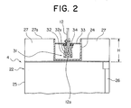
- FIG. 2 is a cross section taken along line II - II in Figure 1, delineation of the equipment accommodated inside the ceiling portion 27 being omitted.
- the rope end connecting apparatus 31 has: a rope shackle 32 functioning as a securing member secured to the car connecting end portion 12a; a supporting member 33 secured to the upper beam 24 so as to be positioned above the rope shackle 32; and a buffering member 34 interposed between the rope shackle 32 and the supporting member 33.
- the rope shackle 32, the supporting member 33, and the buffering member 34 are disposed inside the upper beam 24 (inside a groove formed by the upper beam 24), and are housed within a range of the vertical dimension H of the ceiling portion 27.
- the rope shackle 32 has a wedge rope fastener portion 32a.
- a rubber plate, for example, is used for the buffering member 34.
- the upper beam 24 is disposed horizontally along a width direction of the car 4 so as to divide the ceiling portion 27 generally uniformly in two in a depth direction of the car 4.
- the upper beam 24 is disposed such that a lower extremity portion thereof is positioned lower than an upper surface 27a of the ceiling portion 27, vertical dimensions of the car 4 can be reduced, thereby enabling vertical dimensions of the hoistway 1 to be reduced. Furthermore, overhead dimensions in a top portion of the hoistway 1 can also be reduced, enabling the hoistway to be prevented from projecting through an upper portion of a building, thereby enabling reductions in construction costs and also enabling the appearance of the building to be improved.
- the upper beam 24 is disposed horizontally along a width direction of the car 4 so as to divide the ceiling portion 27 in two in a depth direction of the car 4, the upper beam 24 can be housed within a range of the vertical dimension H of the ceiling portion 27 by a simple construction.
- the rope end connecting apparatus 31 has a rope shackle 32, a supporting member 33, and a buffering member 34, the rope end connecting apparatus 31 can be made compact.
- the main ropes 12 can be connected firmly to the upper beam 24 by a simple construction.
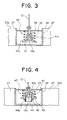
- FIG. 3 is a cross section of a rope end connecting apparatus of an elevator apparatus according to Embodiment 2 of the present invention.
- a rope shackle 41 functioning as a securing member having a wedge rope fastener portion 41a and a spring bearing flange 41b is secured to a car connecting end portion 12a.
- a spring 42 functioning as a buffering member is interposed between the spring bearing flange 41b and a supporting member 33.
- a rope end connecting apparatus 43 includes the rope shackle 41, the supporting member 33, and the spring 42.
- the rope shackle 41, the supporting member 33, and the spring 42 are disposed inside the upper beam 24, being housed within a range of a vertical dimension H of a ceiling portion 27.
- the rest of the construction is similar to that of Embodiment 1.
- FIG. 4 is a cross section of a rope end connecting apparatus of an elevator apparatus according to Embodiment 3 of the present invention.
- a rope shackle 44 functioning as a securing member having a wedge rope fastener portion 44a is secured to a car connecting end portion 12a.
- a screw threaded portion 44b is disposed on an outer peripheral portion of the rope shackle 44.
- An adjusting member 45 for adjusting tension in the main ropes 12 by adjusting its position relative to the rope shackle 44 is screwed onto the screw threaded portion 44b.
- a locknut 46 for locking the position of the adjusting member 45 relative to the rope shackle 44 is also screwed onto the screw threaded portion 44b.
- a rope end connecting apparatus 47 includes the rope shackle 44, the supporting member 33, the spring 42, the adjusting member 45, and the lock nut 46.
- the rope shackle 44, the supporting member 33, the spring 42, the adjusting member 45, and the lock nut 46 are disposed inside the upper beam 24, being housed within a range of a vertical dimension H of a ceiling portion 27.
- the rest of the construction is similar to that of Embodiment 1.
- tension in each of the main ropes 12 can be adjusted by an adjusting member 45, tension in the main ropes 12 can be made more uniform.
Landscapes
- Engineering & Computer Science (AREA)
- Civil Engineering (AREA)
- Mechanical Engineering (AREA)
- Structural Engineering (AREA)
- Lift-Guide Devices, And Elevator Ropes And Cables (AREA)
- Cage And Drive Apparatuses For Elevators (AREA)
Abstract
In an elevator apparatus, a car is suspended inside a hoistway
by a main rope wound around a drive sheave of a driving machine.
The car has an upper beam and a ceiling portion. A car connecting
end portion of the main rope is connected to the upper beam by means
of a rope end connecting apparatus. The upper beam is disposed such
that a lower extremity portion thereof is positioned lower than
an upper surface of the ceiling portion.
Description
The present invention relates to an elevator apparatus in which
a main rope for suspending a car inside a hoistway is connected
to an upper portion of the car.
In conventional elevator apparatuses (machine-roomless
elevators), such as that disclosed in International Publication
No. WO 02/16247 A1, for example, a driving machine for raising and
lowering a car and a counterweight is disposed in an upper portion
inside a hoistway 1. A main rope is wound around a drive sheave
of the driving machine, the car being connected to a first end portion
of the main rope and the counterweight being connected to a second
end portion of the main rope.
The first end portion of the main rope is connected to an upper
beam of the car by means of a rope shackle and a buffering member.
The upper beam is disposed above a cabin.
However, in conventional elevator apparatuses such as that
described above, since the upper beam, the rope shackle, and the
buffering member, etc., are disposed above the cabin, vertical
dimensions of the car are increased. For this reason, it is necessary
to increase overhead dimensions (top portion space dimensions) of
the hoistway, increasing overall vertical dimensions of the
hoistway.
The present invention aims to solve the above problems and
an object of the present invention is to provide an elevator apparatus
enabling vertical dimensions of a hoistway to be reduced.
In order to achieve the above object, according to one aspect
of the present invention, there is provided an elevator apparatus
including a driving machine having a drive sheave; a car raised
and lowered inside a hoistway by a driving force from the driving
machine, having a car frame including an upper beam, and a cabin
supported by the car frame and including a ceiling portion; a main
rope for suspending the car inside the hoistway, having a car
connecting end portion and being wound around the drive sheave;
and a rope end connecting apparatus for connecting the car connecting
end portion to the upper beam, wherein the upper beam is disposed
such that a lower extremity portion thereof is positioned lower
than an upper surface of the ceiling portion.
According to another aspect of the present invention, there
is provided an elevator apparatus including a driving machine having
a drive sheave; a car raised and lowered inside a hoistway by a
driving force from the driving machine, having a ceiling portion;
a main rope for suspending the car inside the hoistway, having a
car connecting end portion and being wound around the drive sheave;
and a rope end connecting apparatus for connecting the car connecting
end portion to an upper portion of the car, wherein the rope end
connecting apparatus is disposed such that a lower extremity portion
thereof is positioned lower than an upper surface of the ceiling
portion.
Preferred embodiments of the present invention will now be
explained with reference to the drawings.
Figure 1 is a general front elevation showing an elevator
apparatus according to Embodiment 1 of the present invention.
In the figure, a pair of car guide rails 2 and a pair of
counterweight guide rails 3 are installed inside a hoistway 1. A
car 4 is guided by the car guide rails 2 while being raised and
lowered inside the hoistway 1. A counterweight 5 is guided by the
counterweight guide rails 3 while being raised and lowered inside
the hoistway 1.
A plurality of car guide shoes 6 for engaging the car guide
rails 2 are disposed on the car 4. A plurality of counterweight
guide shoes 7 for engaging the counterweight guide rails 3 are disposed
on the counterweight 5.
A supporting platform 8 is mounted to an upper end portion
of the guide rails 2 and 3. A driving machine (a hoisting machine)
9 is mounted to the supporting platform 8. The driving machine 9
has: a motor 10; and a drive sheave 11 rotated by the motor 10.
The driving machine 9 has a thin external shape in which an axial
length is smaller than a diameter thereof. In addition, the driving
machine 9 is disposed such that an axis of the drive sheave 11 extends
along a vertical direction. Furthermore, the driving machine 9 is
disposed above a corner portion of the car 4.
A plurality of main ropes 12 (only one is shown in the figure)
are wound around the drive sheave 11. Each of the main ropes 12
has: a car connecting end portion 12a connected to the car 4; and
a counterweight connecting end portion 12b connected to the
counterweight 5. In other words, the car 4 and the counterweight
5 are suspended inside the hoistway 1 using a 1:1 roping method.
A first direction-changing deflection sheave 13 for directing
the main ropes 12 from the driving machine 9 to the car 4, and a
second direction-changing deflection sheave 14 for directing the
main ropes 12 from the driving machine 9 to the counterweight 5
are supported by the supporting platform 8. The first and second
direction-changing deflection sheaves 13 and 14 are disposed such
that rotating shafts thereof extend horizontally. The first
direction-changing deflection sheave 13 and the second
direction-changing deflection sheave 14 are disposed directly above
the car 4 and directly above the counterweight 5, respectively.
The car 4 has: a car frame 21; and a cabin 22 supported by
the car frame 21. The car frame 21 has: a pair of vertical stanchions
21a extending vertically parallel to each other; a lower beam 23
secured between lower end portions of the vertical stanchions 21a;
and an upper beam 24 secured between upper end portions of the vertical
stanchions 21a. The cabin 22 has: a car floor (not shown); cabin
walls 25; a car door 26; and a ceiling portion 27.
The ceiling portion 27 has a predetermined vertical dimension
(a thickness dimension) H, equipment such as lighting equipment
(not shown), etc., being housed inside the ceiling portion 27. The
upper beam 24 is disposed such that a lower extremity portion thereof
is positioned lower than an upper surface 27a of the ceiling portion
27. In this embodiment, the upper beam 24 is housed entirely within
a range of the vertical dimension H of the ceiling portion 27.
The car connecting end portion 12a of each of the main ropes
12 is connected to the upper beam 24 by a rope end connecting apparatus
31. The counterweight connecting end portion 12b of each of the
main ropes 12 is connected to an upper beam 5a of the counterweight
5 by means of a rope shackle 15 and a buffering member 16.
Figure 2 is a cross section taken along line II - II in Figure
1, delineation of the equipment accommodated inside the ceiling
portion 27 being omitted. The rope end connecting apparatus 31 has:
a rope shackle 32 functioning as a securing member secured to the
car connecting end portion 12a; a supporting member 33 secured to
the upper beam 24 so as to be positioned above the rope shackle
32; and a buffering member 34 interposed between the rope shackle
32 and the supporting member 33.
The rope shackle 32, the supporting member 33, and the buffering
member 34 are disposed inside the upper beam 24 (inside a groove
formed by the upper beam 24), and are housed within a range of the
vertical dimension H of the ceiling portion 27. The rope shackle
32 has a wedge rope fastener portion 32a. A rubber plate, for example,
is used for the buffering member 34. The upper beam 24 is disposed
horizontally along a width direction of the car 4 so as to divide
the ceiling portion 27 generally uniformly in two in a depth direction
of the car 4.
In an elevator apparatus of this kind, because the upper beam
24 is disposed such that a lower extremity portion thereof is
positioned lower than an upper surface 27a of the ceiling portion
27, vertical dimensions of the car 4 can be reduced, thereby enabling
vertical dimensions of the hoistway 1 to be reduced. Furthermore,
overhead dimensions in a top portion of the hoistway 1 can also
be reduced, enabling the hoistway to be prevented from projecting
through an upper portion of a building, thereby enabling reductions
in construction costs and also enabling the appearance of the building
to be improved.
Because the upper beam 24 is housed entirely within a range
of the vertical dimension H of the ceiling portion 27, vertical
dimensions of the car 4 can be further reduced, thereby enabling
vertical dimensions of the hoistway 1 to be further reduced.
In addition, because the upper beam 24 is disposed horizontally
along a width direction of the car 4 so as to divide the ceiling
portion 27 in two in a depth direction of the car 4, the upper beam
24 can be housed within a range of the vertical dimension H of the
ceiling portion 27 by a simple construction.
Furthermore, because the rope end connecting apparatus 31 has
a rope shackle 32, a supporting member 33, and a buffering member
34, the rope end connecting apparatus 31 can be made compact.
Because the rope shackle 32, the supporting member 33, and
the buffering member 34 are housed within a range of the vertical
dimension H of the ceiling portion 27, vertical dimensions of the
car 4 can be further reduced, thereby enabling vertical dimensions
of the hoistway 1 to be further reduced.
In addition, because the rope shackle 32 has a wedge rope fastener
portion 32a, the main ropes 12 can be connected firmly to the upper
beam 24 by a simple construction.
Next, Figure 3 is a cross section of a rope end connecting
apparatus of an elevator apparatus according to Embodiment 2 of
the present invention. A rope shackle 41 functioning as a securing
member having a wedge rope fastener portion 41a and a spring bearing
flange 41b is secured to a car connecting end portion 12a. A spring
42 functioning as a buffering member is interposed between the spring
bearing flange 41b and a supporting member 33.
A rope end connecting apparatus 43 includes the rope shackle
41, the supporting member 33, and the spring 42. The rope shackle
41, the supporting member 33, and the spring 42 are disposed inside
the upper beam 24, being housed within a range of a vertical dimension
H of a ceiling portion 27. The rest of the construction is similar
to that of Embodiment 1.
When a rope end connecting apparatus 43 of this kind is used,
vertical dimensions of the car 4 can also be reduced, thereby enabling
vertical dimensions of the hoistway 1 to be reduced.
Next, Figure 4 is a cross section of a rope end connecting
apparatus of an elevator apparatus according to Embodiment 3 of
the present invention. A rope shackle 44 functioning as a securing
member having a wedge rope fastener portion 44a is secured to a
car connecting end portion 12a. A screw threaded portion 44b is
disposed on an outer peripheral portion of the rope shackle 44.
An adjusting member 45 for adjusting tension in the main ropes
12 by adjusting its position relative to the rope shackle 44 is
screwed onto the screw threaded portion 44b. A locknut 46 for locking
the position of the adjusting member 45 relative to the rope shackle
44 is also screwed onto the screw threaded portion 44b.
A rope end connecting apparatus 47 includes the rope shackle
44, the supporting member 33, the spring 42, the adjusting member
45, and the lock nut 46. The rope shackle 44, the supporting member
33, the spring 42, the adjusting member 45, and the lock nut 46
are disposed inside the upper beam 24, being housed within a range
of a vertical dimension H of a ceiling portion 27. The rest of the
construction is similar to that of Embodiment 1.
When a rope end connecting apparatus 47 of this kind is used,
vertical dimensions of the car 4 can also be reduced, thereby enabling
vertical dimensions of the hoistway 1 to be reduced.
Because tension in each of the main ropes 12 can be adjusted
by an adjusting member 45, tension in the main ropes 12 can be made
more uniform.
Moreover, machine-roomless elevators were explained in the
above examples, but the present invention can also be applied to
elevator apparatuses having a machine room.
Claims (8)
- An elevator apparatus comprising:wherein said upper beam is disposed such that a lower extremity portion thereof is positioned lower than an upper surface of said ceiling portion.a driving machine having a drive sheave;a car raised and lowered inside a hoistway by a driving force from said driving machine, having a car frame including an upper beam, and a cabin supported by said car frame and including a ceiling portion;a main rope for suspending said car inside said hoistway, having a car connecting end portion and being wound around said drive sheave; anda rope end connecting apparatus for connecting said car connecting end portion to said upper beam,
- The elevator apparatus according to Claim 1, wherein said upper beam is housed entirely within a range of a vertical dimension of said ceiling portion.
- The elevator apparatus according to Claim 1, wherein said upper beam is disposed horizontally along a width direction of said car so as to divide said ceiling portion substantially uniformly in two in a depth direction of said car.
- The elevator apparatus according to Claim 1, wherein said rope end connecting apparatus has:a securing member secured to said car connecting end portion;a supporting member secured to said upper beam so as to be positioned above said securing member; anda buffering member interposed between said securing member and said supporting member.
- The elevator apparatus according to Claim 4, wherein said securing member, said supporting member, and said buffering member are housed within a range of a vertical dimension of said ceiling portion.
- The elevator apparatus according to Claim 4, wherein said securing member has a wedge rope fastener portion.
- The elevator apparatus according to Claim 4, wherein said buffering member is a spring, and an adjusting member for adjusting tension in said main rope by adjusting a position thereof relative to said securing member is disposed between said securing member and said spring.
- An elevator apparatus comprising:wherein said rope end connecting apparatus is disposed such that a lower extremity portion thereof is positioned lower than an upper surface of said ceiling portion.a driving machine having a drive sheave;a car raised and lowered inside a hoistway by a driving force from said driving machine, having a ceiling portion;a main rope for suspending said car inside said hoistway, having a car connecting end portion and being wound around said drive sheave; anda rope end connecting apparatus for connecting said car connecting end portion to an upper portion of said car,
Applications Claiming Priority (1)
| Application Number | Priority Date | Filing Date | Title |
|---|---|---|---|
| PCT/JP2002/011686 WO2004041702A1 (en) | 2002-11-08 | 2002-11-08 | Elevator equipment |
Publications (2)
| Publication Number | Publication Date |
|---|---|
| EP1602614A1 true EP1602614A1 (en) | 2005-12-07 |
| EP1602614A4 EP1602614A4 (en) | 2011-06-15 |
Family
ID=32310242
Family Applications (1)
| Application Number | Title | Priority Date | Filing Date |
|---|---|---|---|
| EP02778082A Withdrawn EP1602614A4 (en) | 2002-11-08 | 2002-11-08 | ELEVATOR EQUIPMENT |
Country Status (5)
| Country | Link |
|---|---|
| EP (1) | EP1602614A4 (en) |
| JP (1) | JPWO2004041702A1 (en) |
| KR (1) | KR100641307B1 (en) |
| CN (2) | CN1292972C (en) |
| WO (1) | WO2004041702A1 (en) |
Cited By (4)
| Publication number | Priority date | Publication date | Assignee | Title |
|---|---|---|---|---|
| WO2009050113A1 (en) * | 2007-10-11 | 2009-04-23 | Pfeifer Holding Gmbh & Co. Kg | End connector for a cable, combination of a plurality of end connectors, system or device having the same, arrangement having the same and a mounting rail, and use of the same |
| DE202008012659U1 (en) * | 2008-09-25 | 2010-02-25 | Pfeifer Holding Gmbh & Co. Kg | End connection for a cable and system or device with at least one end connection |
| CN101823662A (en) * | 2010-04-13 | 2010-09-08 | 黄海 | Seesaw-type rope end balancing device for forcibly driving elevator |
| EP2751007A4 (en) * | 2011-08-29 | 2015-04-22 | Kone Corp | ELEVATOR CABIN AND ELEVATOR |
Families Citing this family (8)
| Publication number | Priority date | Publication date | Assignee | Title |
|---|---|---|---|---|
| EP2116501A1 (en) * | 2007-02-26 | 2009-11-11 | Mitsubishi Electric Corporation | Elevator rope end device and rope device |
| JP4869385B2 (en) * | 2009-06-26 | 2012-02-08 | 株式会社日立製作所 | Rope elevator |
| FI124543B (en) * | 2012-12-30 | 2014-10-15 | Kone Corp | Linen mount and lift |
| CN104003266B (en) * | 2014-04-14 | 2017-01-25 | 西尼电梯(杭州)有限公司 | Arrangement structure of villa lift |
| JP6395945B2 (en) * | 2015-09-16 | 2018-09-26 | 三菱電機株式会社 | Elevator Bending Car Replacement Method and Bending Car Replacement Jig |
| CN107265247A (en) * | 2017-07-28 | 2017-10-20 | 森赫电梯股份有限公司 | It is a kind of single around high speed passenger lift |
| CN108706430B (en) * | 2018-06-14 | 2023-12-08 | 徐州市三森威尔矿山科技有限公司 | Translation combination beam bearing mechanism |
| CN114455428B (en) * | 2022-01-27 | 2024-08-02 | 西子电梯科技有限公司 | Elevator cable anti-breaking device |
Family Cites Families (16)
| Publication number | Priority date | Publication date | Assignee | Title |
|---|---|---|---|---|
| DE245407C (en) * | ||||
| GB1054349A (en) * | 1900-01-01 | |||
| DE651872C (en) * | 1934-10-09 | 1937-10-21 | Carl Flohr A G | Frameless basket for elevators |
| GB496286A (en) * | 1937-02-25 | 1938-11-25 | Express Lift Co Ltd | Improvements in and relating to elevator cars |
| JPS56117980A (en) * | 1980-02-21 | 1981-09-16 | Tokyo Shibaura Electric Co | Elevator |
| JPS59159680U (en) * | 1983-04-11 | 1984-10-26 | 三菱電機株式会社 | Elevator car device |
| JPS60102385A (en) * | 1983-11-10 | 1985-06-06 | 株式会社東芝 | Cage for elevator |
| FI92182C (en) * | 1992-07-07 | 1994-10-10 | Kone Oy | Pinion Elevator |
| FI98210C (en) * | 1993-06-28 | 1997-05-12 | Kone Oy | Arrangement for unification of elevator machinery with building |
| JPH1077171A (en) * | 1996-09-04 | 1998-03-24 | Toshiba Corp | Elevator hoisting device |
| KR100319936B1 (en) * | 1999-03-04 | 2002-01-09 | 장병우 | Vibration reducing device for elevator car |
| JP4404999B2 (en) * | 1999-08-16 | 2010-01-27 | 三菱電機株式会社 | Elevator equipment |
| JP2001089051A (en) * | 1999-09-17 | 2001-04-03 | Hitachi Ltd | elevator |
| JP2001097649A (en) * | 1999-09-29 | 2001-04-10 | Mitsubishi Electric Corp | Elevator equipment |
| JP3489578B2 (en) * | 1999-12-06 | 2004-01-19 | 三菱電機株式会社 | Elevator equipment |
| US6446763B1 (en) * | 2000-07-19 | 2002-09-10 | Otis Elevator Company | Integrated elevator installation hoist tool |
-
2002
- 2002-11-07 CN CNB028200764A patent/CN1292972C/en not_active Expired - Fee Related
- 2002-11-08 JP JP2004525631A patent/JPWO2004041702A1/en active Pending
- 2002-11-08 KR KR1020047006187A patent/KR100641307B1/en not_active Expired - Fee Related
- 2002-11-08 EP EP02778082A patent/EP1602614A4/en not_active Withdrawn
- 2002-11-08 WO PCT/JP2002/011686 patent/WO2004041702A1/en not_active Ceased
- 2002-11-08 CN CNB028191064A patent/CN1299966C/en not_active Expired - Fee Related
Cited By (5)
| Publication number | Priority date | Publication date | Assignee | Title |
|---|---|---|---|---|
| WO2009050113A1 (en) * | 2007-10-11 | 2009-04-23 | Pfeifer Holding Gmbh & Co. Kg | End connector for a cable, combination of a plurality of end connectors, system or device having the same, arrangement having the same and a mounting rail, and use of the same |
| DE202008012659U1 (en) * | 2008-09-25 | 2010-02-25 | Pfeifer Holding Gmbh & Co. Kg | End connection for a cable and system or device with at least one end connection |
| CN101823662A (en) * | 2010-04-13 | 2010-09-08 | 黄海 | Seesaw-type rope end balancing device for forcibly driving elevator |
| EP2751007A4 (en) * | 2011-08-29 | 2015-04-22 | Kone Corp | ELEVATOR CABIN AND ELEVATOR |
| EP3115328A1 (en) * | 2011-08-29 | 2017-01-11 | KONE Corporation | Elevator car and elevator |
Also Published As
| Publication number | Publication date |
|---|---|
| CN1571753A (en) | 2005-01-26 |
| CN1568282A (en) | 2005-01-19 |
| CN1292972C (en) | 2007-01-03 |
| CN1299966C (en) | 2007-02-14 |
| KR20040068126A (en) | 2004-07-30 |
| KR100641307B1 (en) | 2006-10-31 |
| WO2004041702A1 (en) | 2004-05-21 |
| JPWO2004041702A1 (en) | 2006-03-09 |
| EP1602614A4 (en) | 2011-06-15 |
Similar Documents
| Publication | Publication Date | Title |
|---|---|---|
| US7117977B2 (en) | Elevator apparatus including car with suspending pulley devices on opposite sides of the car | |
| EP1602614A1 (en) | Elevator equipment | |
| US6619433B1 (en) | Elevator system using minimal building space | |
| EP1481935A1 (en) | Elevaltor apparatus | |
| WO2003091141A1 (en) | Elevator | |
| US6302239B1 (en) | Elevator apparatus with hoisting machine beneath elevator car | |
| EP1568644B9 (en) | Elevator equipment | |
| EP1741660A1 (en) | Elevator apparatus | |
| EP1329411B1 (en) | Elevator device | |
| KR100597941B1 (en) | Elevator Winches and Elevator Devices | |
| EP1544150A1 (en) | Elevator equipment | |
| JPWO2006018868A1 (en) | Elevator equipment | |
| JP4397896B2 (en) | Elevator equipment | |
| KR102548320B1 (en) | Flat belt type self-driving elevator for passenger and freight without machine room | |
| EP1571113A1 (en) | Elevator equipment | |
| JP2002205888A (en) | Elevator device | |
| KR200288350Y1 (en) | Elevator | |
| HK1095041A1 (en) | Lift device | |
| HK1095041B (en) | Lift device | |
| HK1138824B (en) | Elevator device | |
| HK1093193A1 (en) | Elevator device | |
| HK1138824A1 (en) | Elevator device | |
| KR20060026486A (en) | Elevator Winches and Elevator Devices |
Legal Events
| Date | Code | Title | Description |
|---|---|---|---|
| PUAI | Public reference made under article 153(3) epc to a published international application that has entered the european phase |
Free format text: ORIGINAL CODE: 0009012 |
|
| 17P | Request for examination filed |
Effective date: 20040325 |
|
| AK | Designated contracting states |
Kind code of ref document: A1 Designated state(s): AT BE BG CH CY CZ DE DK EE ES FI FR GB GR IE IT LI LU MC NL PT SE SK TR |
|
| RBV | Designated contracting states (corrected) |
Designated state(s): DE |
|
| RAP1 | Party data changed (applicant data changed or rights of an application transferred) |
Owner name: MITSUBISHI DENKI KABUSHIKI KAISHA |
|
| A4 | Supplementary search report drawn up and despatched |
Effective date: 20110516 |
|
| STAA | Information on the status of an ep patent application or granted ep patent |
Free format text: STATUS: THE APPLICATION HAS BEEN WITHDRAWN |
|
| 18W | Application withdrawn |
Effective date: 20110614 |