EP1602495A1 - Anordnung und Verfahren zur Ansteuerung eines Thermotransferdruckkopfes - Google Patents
Anordnung und Verfahren zur Ansteuerung eines Thermotransferdruckkopfes Download PDFInfo
- Publication number
- EP1602495A1 EP1602495A1 EP05009546A EP05009546A EP1602495A1 EP 1602495 A1 EP1602495 A1 EP 1602495A1 EP 05009546 A EP05009546 A EP 05009546A EP 05009546 A EP05009546 A EP 05009546A EP 1602495 A1 EP1602495 A1 EP 1602495A1
- Authority
- EP
- European Patent Office
- Prior art keywords
- encoder
- pulses
- pulse
- pulse generator
- counter
- Prior art date
- Legal status (The legal status is an assumption and is not a legal conclusion. Google has not performed a legal analysis and makes no representation as to the accuracy of the status listed.)
- Granted
Links
- 238000012546 transfer Methods 0.000 title claims abstract description 41
- 238000000034 method Methods 0.000 title claims abstract description 23
- 238000010438 heat treatment Methods 0.000 claims abstract description 79
- 238000007639 printing Methods 0.000 claims description 115
- 230000008859 change Effects 0.000 claims description 24
- 238000007651 thermal printing Methods 0.000 claims description 13
- 230000003111 delayed effect Effects 0.000 claims description 9
- 230000008569 process Effects 0.000 claims description 4
- 238000010586 diagram Methods 0.000 description 45
- 230000000694 effects Effects 0.000 description 18
- 230000001276 controlling effect Effects 0.000 description 12
- 240000007320 Pinus strobus Species 0.000 description 7
- 238000001816 cooling Methods 0.000 description 5
- 230000006870 function Effects 0.000 description 5
- 239000011159 matrix material Substances 0.000 description 5
- 101000650578 Salmonella phage P22 Regulatory protein C3 Proteins 0.000 description 4
- 101001040920 Triticum aestivum Alpha-amylase inhibitor 0.28 Proteins 0.000 description 4
- 230000006399 behavior Effects 0.000 description 3
- 238000013461 design Methods 0.000 description 3
- 239000000463 material Substances 0.000 description 3
- 238000001208 nuclear magnetic resonance pulse sequence Methods 0.000 description 3
- 230000001360 synchronised effect Effects 0.000 description 3
- 238000010023 transfer printing Methods 0.000 description 3
- 230000008901 benefit Effects 0.000 description 2
- 230000033228 biological regulation Effects 0.000 description 2
- 239000012876 carrier material Substances 0.000 description 2
- 238000011161 development Methods 0.000 description 2
- 230000018109 developmental process Effects 0.000 description 2
- 238000005516 engineering process Methods 0.000 description 2
- 238000004519 manufacturing process Methods 0.000 description 2
- 230000007704 transition Effects 0.000 description 2
- 230000003313 weakening effect Effects 0.000 description 2
- 241001136792 Alle Species 0.000 description 1
- 230000009471 action Effects 0.000 description 1
- 230000003466 anti-cipated effect Effects 0.000 description 1
- 230000003139 buffering effect Effects 0.000 description 1
- 239000003990 capacitor Substances 0.000 description 1
- 239000000969 carrier Substances 0.000 description 1
- 239000003795 chemical substances by application Substances 0.000 description 1
- 238000005352 clarification Methods 0.000 description 1
- 230000006835 compression Effects 0.000 description 1
- 238000007906 compression Methods 0.000 description 1
- 238000007796 conventional method Methods 0.000 description 1
- 230000003247 decreasing effect Effects 0.000 description 1
- 230000007812 deficiency Effects 0.000 description 1
- 230000001419 dependent effect Effects 0.000 description 1
- 230000017525 heat dissipation Effects 0.000 description 1
- 230000006872 improvement Effects 0.000 description 1
- 230000001788 irregular Effects 0.000 description 1
- 230000007774 longterm Effects 0.000 description 1
- 238000012423 maintenance Methods 0.000 description 1
- 239000000155 melt Substances 0.000 description 1
- 238000002844 melting Methods 0.000 description 1
- 230000008018 melting Effects 0.000 description 1
- 238000013021 overheating Methods 0.000 description 1
- 239000005022 packaging material Substances 0.000 description 1
- 238000012545 processing Methods 0.000 description 1
- 230000001737 promoting effect Effects 0.000 description 1
- 230000000306 recurrent effect Effects 0.000 description 1
- 230000009467 reduction Effects 0.000 description 1
- 230000001105 regulatory effect Effects 0.000 description 1
- 230000000630 rising effect Effects 0.000 description 1
- 238000004904 shortening Methods 0.000 description 1
- 238000003860 storage Methods 0.000 description 1
- 239000000758 substrate Substances 0.000 description 1
- 230000002123 temporal effect Effects 0.000 description 1
Images


Classifications
-
- B—PERFORMING OPERATIONS; TRANSPORTING
- B41—PRINTING; LINING MACHINES; TYPEWRITERS; STAMPS
- B41J—TYPEWRITERS; SELECTIVE PRINTING MECHANISMS, i.e. MECHANISMS PRINTING OTHERWISE THAN FROM A FORME; CORRECTION OF TYPOGRAPHICAL ERRORS
- B41J2/00—Typewriters or selective printing mechanisms characterised by the printing or marking process for which they are designed
- B41J2/315—Typewriters or selective printing mechanisms characterised by the printing or marking process for which they are designed characterised by selective application of heat to a heat sensitive printing or impression-transfer material
- B41J2/38—Preheating, i.e. heating to a temperature insufficient to cause printing
Definitions
- the invention relates to an arrangement for controlling a thermal transfer print head according to the preamble of claim 1 and a Method for controlling a thermal transfer print head according to The preamble of claim 11.
- the invention is particularly in Franking machines, addressing machines and similar booking or Mail processing equipment used.
- Applicant's thermal transfer postage meter T1000 has a fixed in the housing thermal transfer print head for printing a franking imprint and a compartment attached to the outside of the housing for holding a removable thermal transfer ribbon cassette, the compartment enclosing a non-safety area.
- a mail piece becomes synchronous with the thermal transfer ribbon by the printing station moved, wherein the movement is monitored by a detector, the generates an output signal from which a parameter of the band movement is proportional (EP 189269 B1 equivalent US 4705417).
- European Patent EP 536 526 B1 has already disclosed a method for Controlling the supply of a thermal print heating element proposed.
- a pressure requirement determined.
- Both for the raster points without Druck Profis, as well as for the raster points with Druck Victoriais takes place an output of current pulses to the respective Thermoyakheizelement.
- European Patent EP 730 972 B1 has already published a print head thermo-control system suggested that a pressure control unit associated power electronics the amplitude of the print head voltage according to the ambient temperature and with a control unit combined, following a predictive control process for feeding individual thermal pressure heating elements with preheating and Pressure pulses of variable pulse duration works.
- Such a security imprint includes previously entered and stored postal information, including the postal fee data for carrying the letter and possibly a mark with security information.
- billing and storage of postage fee data (EP 789 333 B1) and internal security measures (US Pat. No. 6,351,220 B1, DE 299.05.219 U1, DE 201.12.350 U1) are carried out by a postal security module arranged inside the meter housing and the generates the aforementioned safety information (DE 199.28.058 A2, US 6,041,704).
- the precalculation of security information requires a large part of the time in the postal security module and thus the security information is available relatively late for embedding in the print image.
- the Thermodigmosetti by preheating pulses to a preheating temperature to be relatively close to the aforementioned limit temperature without exceeding the latter, on the one hand, the maximum possible duration of preheating is limited by the reduced distances between the successive Haupttogetherimpulsen. On the other hand, the practically controllable maximum possible Vorteximpulhehehe is also limited.
- Conventional methods for thermal transfer printing control the temperature at the individual thermal print heating elements of the print head by a variety of methods. With a high print image resolution and transport speed, the print image of the first print nips appears to be printed weaker at the beginning of printing than in the other print nips of a stamp print.
- the invention is based on the object, an arrangement and method to develop a thermal transfer print head, which the does not have the above-mentioned disadvantages.
- a thermal transfer print head which the does not have the above-mentioned disadvantages.
- the Influence of fluctuations in the relative speed between Print material and print head are suppressed on the printed image, with the Solution should cause only low production costs.
- the object is achieved with the features of the arrangement according to the claim 1 or with the features of the method for controlling a Thermal transfer printing head solved according to claim 11.
- the individual thermal printing heating elements the print head is not sufficient for printing thermal energy on to print dots on the print substrate surface (envelope, card, Strip or other print material) machine-printable and the Energy control needs to be changed.
- the print substrate surface envelope, card, Strip or other print material
- the Energy control needs to be changed.
- franking machines in which mail pieces at a transport speed below a fixed Printhead is moved past, also encounter difficulties because of the uneven thickness of the mail pieces. If the o.g. Deficiency can be eliminated, then succeed in other printing machines.
- subsequently being spoken by mail pieces should All other possible print carrier or printed matter to be included.
- a printhead on a fixed Print carrier is moved at a transport speed.
- auxiliary heat pulses are given to the respective Thermodruckmoside in the temporal gap between successive printing columns, for which there is a Drucker Techis and which have just printed.
- the length of the pressure pulses or the length of the pause between the pressure pulses are dependent on the resistance of the heating element and the thermal behavior, such as compressive stress, melting point of the thermal transfer ribbon, print carrier material (packaging material) of the mailpiece and heat dissipation of the printing system and must be determined according to the particular application.
- the print quality is thereby significantly improved because no weak printed areas occur, which are caused by speed fluctuations.
- the assembly includes first means for determining a transport delay and second means for generating auxiliary heating pulses for maintaining a temperature required for printing on the thermal printing heating elements, the first means being connected to the thermal transfer print head via the second means.
- the first means for determining a transport delay includes a counter which counts a number of clock pulses of a clock signal until the counter is reset.
- the first means include an edge detector which processes undelayed and delayed encoder pulses into an encoder pulse train which identifies an encoder pulse edge at each H / L and L / H edge transition with a narrow pulse, the counter being reset by the pulse.
- the first means includes logic for enabling the generation of auxiliary heating pulses when a predetermined number of counted clock pulses are exceeded or overflowed prior to the next encoder pulse edge transition.
- the method of driving a thermal transfer printhead comprises the steps of a) determining a transport delay and b) generating auxiliary heating pulses to maintain a temperature required for printing on the thermal printing heating elements for which a printing requirement exists.
- the time interval between the raster points in time is determined by the transport speed detected by the encoder and the desired horizontal print resolution. This allows a determination of a transport delay compared to the desired time interval of the raster points. It is provided that the determination of a transport delay based on a missing encoder edge change before a CLK overflow of the counter or exceeding a predetermined count is detected.
- the auxiliary heating pulses serve to maintain a temperature required for printing on the thermal printing heating elements, so that upon a transport delay the printing of a dot is not completed before reaching a printing nip to be printed at a predetermined screen dot.
- the spatial spacing of the screen dots in the print pattern also remains constant.
- the invention has the advantage that preserving the temperature at the thermal print heating elements for the printing of pixels despite a transport delay can be achieved without the use of computing power.
- FIG. 1 shows a monochrome printing pattern with spatially constant spaced grid points.
- the first printed field 1 is a Initial weakening of the print pattern and in the middle field 2 is the Chatter effect by weakly printed areas for clarification exaggeratedly visible.
- the ones shown in the middle field 2 Print pixels D1 ', D2', D3 'and Dn' are part of the grid-like Printing pattern and are explained below.
- FIG. 2 shows a block diagram for controlling a thermal transfer printer.
- the invention will be clarified using the example of a franking machine.
- a thermal transfer printhead 1 is provided with a shift register 11, a memory latch unit 12 and drive unit 13, and a row 14 of thermal print heaters 1411 to 177x arranged orthogonal to the mail item transport direction.
- the thermal transfer printhead 1 is connected via the shift register 11 to the serial data output of a print data controller 4, which adopts 16 bits of parallel binary print image data from a bus 5 on the input side and outputs binary print image data on the output side in a direct memory access.
- At least one microprocessor 6, a pixel memory 7, a nonvolatile memory 8 and a read-only memory 9 are connected in terms of address, data and control via the BUS 5.
- An encoder 3 is connected to the print data controller 4 to synchronously trigger the buffering of the binary pixel data and the printing of the print image columns, the print head being driven at a clock frequency having a transport speed of about 150 mm per second for mail pieces up to 10 mm thick allowed.
- the print data controller 4 is connected to a motor 2 for driving a mail piece conveying device in the transporting direction (white arrow). It is provided that a printer controller 45 having a DMA controller 43, a pixel data providing unit (40) and an auxiliary pulse generator 41, and that the DMA controller 43 are connected to the pixel data providing unit 40 in control.
- the pixel data providing unit 40 is connected via the BUS 5 and the printer controller 45 is connected directly to the microprocessor 6 via the BUS 5 and via an interrupt signal control line 47.
- the DMA controller 43 is connected to the microprocessor 6 via a control line for DMA control signals DMA ACK , DMA REQ .
- the printer controller 45 provides via the output Q1 a shift clock signal to the pixel data providing unit 40 and to the shift register 11.
- the printer controller 45 provides via the output Q2 a latch signal to the memory latch unit 12 for holding and latching the data.
- the printer controller 45 provides via output Q5 a start signal to the auxiliary pulse generator 41, the output Q6 outputs an auxiliary pulse signal, which is logically linked via a logical OR 42 with a strobe signal, which is supplied via output Q4 of the printer controller 45.
- the output of the OR link 42 is applied to a control input of the driver unit 13, via the control input both the strobe signal and the auxiliary pulses are supplied, which switch the switches of the driver unit 13 for driving the thermal printing elements of the thermal transfer print head.
- the switches can be advantageously designed as AND gates or as transistors. Each switch or AND gate or transistor are each assigned a latch of the memory latch unit 12, which takes over information for a preheat or pressure requirement of the respective pixel and holds it with the latch signal.
- the series / parallel shift register 11 supplied with the serial print data by the pixel data providing unit 40 transfers the print data to the memory latch unit 12 in a first drive phase.
- each gate driven by the associated latches of the memory latch unit 12 is the driver unit during a strobe pulse 13 switched to passage and issued a Schustromimpuls to the respective Thermoyakheizelement.
- the respective Thermoyak carvingiata for which there is a Vor carving- or Druck Schwarzeauis are preheated directly by Schustromimpulse, which are adapted in their pulse height and pulse width to the required heating energy.
- the main control board of a postage meter includes a security module 10, which is inserted directly or via an adapter.
- the Security module 10 for a franking machine is referred to below as PSD (Postal Security Device).
- PSD Postal Security Device
- the PSD can be omitted.
- the main control board of a postage meter also contains other - not shown interfaces - for example, for connection a keyboard and a display unit.
- the means for determining a transport delay during printing are arranged in the printer controller 45.
- the auxiliary pulse generator 41 is used to generate Hilfshardimpulsen for maintaining temperature on thermal printing elements to avoid the chatter effect.
- the entire print data controller 4 can preferably be realized with an application-specific circuit (ASIC) or programmable logic, such as, for example, the Spartan-II 2.5 V FPGA from XILINX ( www.xilinx.com ). More information about field programmable gate array chips and related techniques will be given in connection with FIG. 3a.
- FIG. 3a shows a circuit arrangement with means for determining a transport delay and for controlling the auxiliary pulse generator.
- a pulse generator 452 which is supplied on the input side with the encoder signals, clock signal and a reset signal, provides an encoder pulse train at its first output Q3, strobes at its second output Q4 and an enable pulse at its third output Q5 at a transport delay.
- the pulse generator 452 is, for example, part of a hardware circuit and has a counter 4521, an edge detector 4522, a heat pulse generator 4523 and an enable logic 4524.
- the counter 4521 is connected with its reset input to the output of a logic gate 451 and connected to its clock input, for example with a timer 454.
- the timer 454 already outputs a pre-divided clock and the counter 4521 at its four outputs Q A , Q B , Q C and Q D outputs a binary code for the number of counted clock pulses since a reset of the counter.
- the clock 454 may be omitted and the number of counter outputs may be greater than four when a clock signal of the microprocessor 6 of the controller is used on the motherboard.
- the logic gate 451 is, for example, a NAND gate, which is supplied at its one input with a control signal RST_CLK and at its other input with a processed encoder pulse signal which is output at the output Q7 of a pulse filter 453.
- the input of the pulse filter 453 is connected to the output Q3 of the edge detector 4522 and outputs a short pulse at each edge change of the encoder pulses e1 and e2, which is used to reset the counter at each edge change of the encoder pulses.
- the pulse filter 453 includes an analog or a digital element which suppresses spikes and other disturbances in the encoder pulse train.
- Logic gate 451 may alternatively be an AND gate if required by the type of counter used. In the simple case, JK flip-flops are connected in series in the counter, the output of the predecessor being connected to an input of the successor flip-flop.
- the enable logic 4524 logically links some of the outputs of the counter to the output of the clock 454 to generate further pulses as needed and in synchronism with the edge change of the encoder signals, and may be reprogrammable by the microprocessor 6, for example.
- the heating pulse generator 4523 is likewise designed to be programmable by the microprocessor 6 and emits strobe pulses at its output Q4 which arrive as heating pulses on the respective thermal printing heating elements of the thermal transfer printing head which are driven for printing.
- the enable logic 4524 outputs an enable signal at the output Q5 to enable an auxiliary pulse generator 41.
- the output Q4 of the heat pulse generator 4523 and the output Q6 of the auxiliary pulse generator 41 are, for example, in the embodiment shown in Figure 3a - as an alternative to the variant shown in Figure 2 with OR gate 42 - the output side via a wired-OR operation logic 420 together connected. This requires an open collector output at the auxiliary pulse generator 41 and the heat pulse generator 4523. An additional OR gate 42 can thus be dispensed with.
- Another difference of the embodiment variant compared to the variant shown in Figure 2 consists in the supply of two encoder signals e1 and e2.
- pulse generator 452 and a Encoder type for example, with integrated edge detectors conceivable. If - depending on the type of encoder used - only one single encoder signal is provided that already the required encoder pulse sequence, which at the output Q3 and If necessary Q7 occurs, then in the circuit 450 of the Edge recognizer 4522 and possibly the pulse filter 453 omitted.
- a variety of embodiments of the circuit arrangement 450 with means for determining a transport delay and for controlling the auxiliary pulse generator is possible. Execution as a hardware circuit is required to improve the execution time.
- a field programmable gate array (FPGA) chip and other programmable logic ICs are ideal for this.
- An FPGA is an integrated circuit that contains many thousands of identical logic cells as standard components (up to 50,000 in the XC2S50 from XILINX). Each logic cell can independently assume any of a limited set of properties.
- the individual cells are interconnected by a matrix of lines and programmable switches.
- a user's design is introduced by specifying the simple logic function for each cell and selectively closing the switches in the join matrix. Complex designs are created by combining these basic blocks to create the desired circuit.
- These blocks form field programmable means whose advantageous function is to define the latter by a program of the user rather than by the manufacturer of the device.
- the program is either internally permanently or semi-permanently burned as part of a board assembly process, or is loaded from external memory at any time when the aforementioned printing device is turned on.
- the configuration data for the FPGA XC2S50 comprise approx. 0.6 GBit and are stored in the read-only memory FLASH 9 (Fig.2).
- the use of an FPGA chip and related techniques offers the advantage that the programmable logic saves development costs and time over an increasingly complicated ASIC design, with the number of gates per FPGA chip now reaching numbers that support the implementation of allow more and more complicated applications.
- circuitry 450 may be implemented with conventional technology as hardwired circuitry of positive and / or negative logic gates.
- FIG. 3b pulse / time diagrams of the circuit arrangement 450 are shown shown.
- the heat pulse generator 4523 generates at its output Q4 preheat pulses H1p, H2p, H3p, .... Hnp and each following Main heat pulses H1m, H2m, H3m, .... Hnm (last diagram of FIG 3b). If a pressure requirement for the corresponding resistance heating element present in the printhead and reaches the preheat temperature is, is due to an edge change of the encoder signals Main heat pulse started. The flank change becomes a short one Pulse S1 derived (encoder pulse sequence at output Q7). The release logic can exceed a predetermined count Nx and thus determine a transport delay and then generates a signal suitable for controlling the auxiliary pulse generator Output Q5 (see fifth diagram of Figure 3b).
- the counter is read after the occurrence of the first H / L edge of the CLK_RESET signal and when there is an H level of the RST_CLK signal started, which is apparent from the first diagram of Figure 3b.
- the counter is supplied with a clock signal, which results from the sixth Diagram of Figure 3b shows.
- the pulse train at the outputs of the counter is from the seventh to tenth diagrams of Figure 3b out.
- the release logic generates from the signal levels to the Outputs of the counter an L signal at output Q5, resulting from the fifth diagram of Figure 3b shows.
- the auxiliary pulse generator is active and generates auxiliary heating pulses H1a, H2a, ..., which is apparent from the fourth diagram of Figure 3b.
- FIG. 4a shows a circuit arrangement for an auxiliary pulse generator 41.
- a capacitor C is between ground potential and the Output of a first gate G1 is switched and charges up to a Threshold on a resistor R, where when exceeding the Threshold a downstream second gate G2 switches.
- the Gates can, for example, NAND gates in TTL technology or as Schmidt trigger to be trained.
- At the output of the second gate G2 is a negator connected, for example, as the third gate G3 or npn transistor T3 is formed in emitter circuit.
- Whose Collector resistor R3 is connected to operating voltage + Us and can be saved in the case of a wired OR connection.
- Of the Output of the second gate G2 is at a first input of the first G1's gate is fed back, its second input with the Q5 signal is charged.
- Figure 4b is a pulse / time diagram for auxiliary pulses at the output Q6 and for the Q5 signal at the first input of the first gate G1 of the Auxiliary pulse generator 41 shown.
- FIG. 5 shows a flow chart for a means for determining a delay and for controlling the auxiliary pulse generator. Even if the pulse generator is constructed in parts other than as shown in FIG. 3a, its circuit should have the function illustrated in the flow chart, which corresponds to the following method 700: After the start in step 701, a first interrogation step 703 is reached detect an encoder edge change. If the latter has not yet taken place, then a branch is made to a second interrogation step 704 in order to determine a CLK overflow of the counter or the exceeding of a predetermined counter reading. If the answer is no, ie the latter has not occurred, then a fourth interrogation step 707 is reached to determine if the auxiliary pulse generator is active.
- a first interrogation step 703 detect an encoder edge change. If the latter has not yet taken place, then a branch is made to a second interrogation step 704 in order to determine a CLK overflow of the counter or the exceeding of a predetermined counter reading. If the answer is no,
- the system branches back to the first query step 703. If, however, an encoder edge change has taken place, then the system branches to a step 702 resetting the counter. Thereafter, the fourth interrogation step 707 is reached again. If the answer is then no again, ie the auxiliary pulse generator is not active, the system branches back to the first interrogation step 703. In the case of a transport delay, however, no encoder edge change will take place before a predetermined counter reading or overflow has been reached. Then the answer to the first query step 703 is no and again the second query step 704 is reached.
- a CLK overflow of the counter or the exceeding of a predetermined count is detected, then the answer is yes and a third interrogation step 705 is reached to determine whether the auxiliary pulse generator is active. If the answer is no, ie the latter is inactive, then a step 706 is reached and the auxiliary pulse generator is switched on. Subsequently, the first query step 703 branches back.
- the system branches back to the first interrogation step 703 as well. If the answer given to the fourth interrogation step 707 is yes, ie the latter is active, then a step 708 for switching off the auxiliary pulse generator is reached. Subsequently, the first query step 703 is branched back again.
- Figure 6a shows a pulse / time diagram for slow printing a series of pressure pulses (prior art).
- slowly Speed variations affect the mailpiece transport speed Less annoying in the print image, than the fast Print a sequence of print pixels. It is therefore sufficient for a possible Deviation from a target speed before or after Correcting printing while printing from an average transport speed to go out when the pulse duration of Heating pulses of the strobe signal is determined.
- the auxiliary current pulses I1 and I2 are in time before a Hauptstromimuls I3, which on a heating element switched the latter heated and a thermal transfer ribbon caused the impression of a dot on a piece of mail.
- Such a consequence of current pulses of increasing pulse width for applying a Resistance heating element already goes from the patent EP 536526 B1 out.
- FIG. 6b shows a pulse / time diagram of an associated encoder pulse train.
- the time interval of the adjacent pulses S1 to Sn the encoder pulse train reflects the current mailpiece transport speed again.
- each associated Hauptstromimuls is synchronized.
- FIG. 6c shows a temperature / time diagram on a heating element for slowly printing a sequence of pressure pulses.
- the auxiliary current pulses I1 and I2 are started at the times t I and t II and lie ahead of a main current pulse I3, which is started at time t III .
- a main current pulse I3 which is started at time t III .
- a pulse / time diagram for a fast printing of a sequence of pressure pulses is illustrated by a single resistance heating element in the ideal case. Only one individual preheating current pulse I H1 *, ..., I Hn * is in time before each main heating current pulse I H2 *, ..., I Hn + 1 *.
- the pulse intervals on the one hand between the Vorholicstromimpuls and the subsequent Schofindstromimpuls and on the other hand between the previous Hauptrichstromimpuls and the Vorholicstromimpuls the respective subsequent Schobasedstromimpulses are reduced.
- the distance between the main heating current pulses I H2 *, ..., I Hn + 1 * has been reduced in order to achieve a higher print image resolution in the transport direction.
- FIG. 7b shows a pulse / time diagram of an associated encoder pulse train.
- the time interval of the adjacent pulses S1 * to Sn * the encoder pulse train reflects the achievable resolution for one Determine the current mailpiece transport speed again.
- the printing speed is uniform and constant. With one each Pulse S1 * to Sn * of the encoder pulse train is again associated with each Main current pulse synchronized.
- the temperature / time diagram illustrated in FIG. 7c reflects the temperature profile on a single heating element for a fast printing of a series of pressure pulses.
- the temperature limit ⁇ L is only exceeded by the main current pulse I H2 *, ..., I Hn + 1 *.
- a drop in temperature to the value of the operating temperature ⁇ B is allowed only temporally after each Hauptstromimuls, with a subsequent Vortexstromimpuls allowed by its preheating effect, the temperature limit ⁇ L approximately to reach again.
- preheating pulses (not shown) allow only the value of the operating temperature ⁇ B to be reached again and do not lead to the printing of a dot.
- FIG. 7d shows a pixel / time diagram for a fast printing of a sequence of print pixels, wherein the printing speed is uniformly constant and no transport delay occurs.
- a pixel P1 * to Pn * to be printed is the smallest data unit which identifies an object in a computer graphic and is shown in color (blackened). At higher print speeds, appropriate action is taken not only to pre-distort the print pattern but also to the duration of the pixel to print each dot.
- Figure 8a shows a pulse / time diagram for fast printing of a sequence of print pulses and transport delay.
- a transport delay results in a greater time gap between the main heating current pulse I H2 'and the subsequent preheating current pulse I H3 ' of the main heating current pulse I H4 'than between the main heating current pulse I H4 ' and the subsequent preheating current pulse I H5 'of the main heating current I H6 '. Due to a delayed encoder pulse after the printed first print dot, a temperature drop on the heating element is measurable, which interferes with the further pressure.
- FIG. 8b shows a pulse / time diagram of an associated encoder pulse train with transport delay ⁇ t, which is a delay of second pulse of the encoder pulse train makes noticeable.
- FIG. 8d shows a pixel / time diagram for a fast printing of a sequence of print pixels and during transport delay. Predistortion of the pixels is intended to prevent compression of the form in the transport direction during printing. Despite the predistortion of the time duration of printing each dot, a first time axis stretched pixel P1 'is printed as a compressed dot D1' during printing (Fig.1) because, in a transport delay, the printing of a dot is finished rather than the transport over the associated transport route. In addition, instead of starting at a time t 6 ', a second pixel P2' is not printed until a time t 7 'since the temperature limit value ⁇ L was not reached during preheating.
- the second pixel P2 ' is supposed to have the dash dot shape, but has only the colored (blackened) shape. This also applies to a third pixel P3 '.
- the operating temperature is reached again by means of a plurality of preheating pulses or a preheating pulse having a sufficient pulse duration only after a period of time (printing pause) required by an appropriate regulation, so that another pixel Pn 'stretched in the time axis direction is printed during printing as a circular dot Dn' ( Fig.1).
- Figure 9a shows a pulse / time diagram for a sequence of pressure pulses and with compensation for the effect caused by the transport delay.
- FIG. 9b shows a pulse / time diagram of an associated encoder pulse train with a delay as shown in FIG. 8b.
- FIG. 9c shows a temperature / time diagram on a heating element for a sequence of print pixels to be printed.
- FIG. 9d shows a pixel / time diagram for a sequence of print pixels.
- the first pixel P1 is extended in the transport direction, thereby compensating for the temperature drop in the heating element that is otherwise caused by the transport delay.
- the first pixel P1 has a part a caused by a main heat pulse.
- the first pixel P1 also has a part b and c caused by an auxiliary heating pulse.
- the effective total length of the pressure pulses due to a main heat pulse and auxiliary heat pulses is extended beyond the designated raster timing when there is a pressure requirement and a transport delay is detected.
- the length of a pressure pulse is always smaller than the distance of the raster points from each other.
- the length of the pressure pulses in dependence of at least one of the aforementioned parameters is variable.
- the length of the Hilfscreamimpulse or the pause between the auxiliary heating pulses as a function of at least one of the aforementioned parameters is variable.
- This is the Hilfshackimpulsgenerator 4523 ( Figure 3a) controllable or from the microprocessor 6 adjustable formed.
- the pulse pause length is between those immediately apart spaced pressure pulses to choose larger than at higher Resistance value.
- FIG. 10a shows a detail of the printing pattern according to FIG evenly slow printing of a sequence of print pixels a thermal print heating element 1411 on a print carrier surface.
- the Print carrier envelope, strip
- the first thermal print heating element 1411 which is heated, so the via thermal transfer ribbon ever a Dot DI, DII and DIII successively printed in the printing columns CI, CII and CIII.
- FIG. 10b shows a detail of the printing pattern according to FIG. 1 for a uniformly fast printing of a sequence of printed image points by a heating element.
- FIG. 10c shows a detail of the printing pattern according to FIG evenly slow printing of a sequence of closely spaced ones Print image points through a heating element. This measure will a doubling of the print resolution in the transport direction possible, wherein but additional dots are provided in the transport direction have to.
- the transport speed v remains unchanged and became as selected in Fig.10a.
- Via thermal transfer ribbon are each a dot DI °, DII °, DIII ° and Dn ° successively in the pressure gaps CI °, CII °, CIII ° and Cn ° printed. In the above example, only in the Print column CIV ° no dot printed.
- FIG. 10d shows a detail of the printing pattern according to FIG. 1 for a uniformly fast printing of a sequence of closely adjacent print image points by a heating element.
- the clock period is now for example 2/3 T.
- the transport speed v remains unchanged and was selected as in FIG. 10a.
- a dot DI ", DII”, DIII “and Dn” are successively printed in the printing columns CI ", CII", CIII “and Cn”.
- no dot is printed only in the print column CIV.
- the print image resolution has been increased by 1.5 times by this measure and the distortions of the dots remain minimal, which facilitates equalization of the dots.
- FIG. 10e shows a detail of the printing pattern according to FIG. 1 for a uniformly fast printing of a chronologically predistorted sequence of closely adjacent print image points by a heating element.
- the transport speed v remains unchanged and was selected as shown in Fig.10a.
- Via thermal transfer ribbon one dot each D1 *, D2 *, D3 * and Dn * are successively printed in the printing columns C1 *, C2 *, C3 * and Cn *.
- no dot is printed only in the print column C4 *.
- FIG. 10f shows a detail of the printing pattern according to FIG. 1 for a non-uniformly fast printing of a sequence of closely adjacent print image points by a heating element.
- a change in the transport speed v is not provided.
- Via thermal transfer ribbon one dot D1 ', D2', D3 'and Dn' are successively printed in the printing gaps C1 ', C2', C3 'and Cn'.
- no dot is printed only in the print column C4 '. Based on the example of Figure 8, the effect of the transport delay has already been explained.
- the printed dot D1 ' is adjacent to the printing columns C1', and the size of the dots D2 ', D3' in the printing columns C2 'and C3' are reproduced compressed in the transporting direction (arrow) of the printing medium (not shown).
- FIG. 10g shows a detail of the printing pattern according to FIG. 1 for one unevenly fast printing of a series of closely spaced ones Printed pixels by a heating element with compensation of the effect by a delayed encoder pulse.
- a thermal transfer ribbon One dot each D1, D2, D3 and Dn are successively in the pressure columns C1, C2, C3 and Cn printed. In the above example is again in the print column C4 no dot printed.
- the detail of the print pattern is similar to the ideal case of FIG. 10e.
- a change in the transport speed v is not intended.
- the above explained measure allows error-free printing with horizontal print resolution of over 600 dpi.
- the vertical print resolution can also increased by the appropriate value by a printhead type is used, in which the number of Thermodruckmosetti on over 600 in the orthogonal to the transport direction arranged pressure row 14 of the printhead is increased.
Landscapes
- Electronic Switches (AREA)
Abstract
Description
Für den Thermotransferdruckkopf ist bereits aus der DE 38 33 746 A1 eine über eine externe Ansteuereinheit beaufschlagte interne Schalteinheit bekannt, welche in den Druckkopf integriert ist, der die in einer einzigen Reihe angeordneten Thermodruckheizelemente enthält, was eine selektive Ansteuerung mit Vorheizung der Thermodruckheizelemente zu Verringerung der Heizleistung beim Drucken ermöglicht. Die Widerstandsheizelemente werden unmittelbar durch eine in Impulshöhe und Impulsbreite an die benötigte Heizenergie angepasste Taktfrequenz auf eine Vorheiztemperatur vorgewärmt. Am Ende der Druckzeit wird die Vorheiztemperatur durch eine ebensolche Taktfrequenz aufrechterhalten.
Die Vorausberechnung einer Sicherheitsinformation benötigt einen Großteil der Zeit im postalischen Sicherheitsmodul und somit steht die Sicherheitsinformation erst relativ spät zur Einbettung in das Druckbild zur Verfügung. Selbst eine teilweise Vorausberechnung von Sicherheitsinformationen weit vor einem Frankieren durch die Frankiermaschine kann nicht verhindern, dass der Matrix-Code im Markierungsfeld von Poststück zu Poststück wechselt. Das erschwert es, vorausschauend ein Druckerfordernis noch rechzeitig zu ermitteln. Das Ausdrucken eines maschinenlesbaren Matrix-Codes erfordert eine höhere Anzahl an Rasterzeitpunkten entsprechend der höheren Druckauflösung, was ebenfalls eine höhere Rechenleistung bindet. Erschwerend wirkt sich auch eine Forderung nach einem 25-50 % schnelleren Poststücktransport aus. Die Rasterzeitpunkte folgen in kürzeren Abständen aufeinander, je höher die Poststücktransportgeschwindigkeit gewählt wird. Sollen die Thermodruckheizelemente mittels Vorheizimpulsen bis zu einer Vorheiztemperatur bis relativ nahe der vorgenannten Grenztemperatur vorgeheizt werden ohne letztere zu überschreiten, wird einerseits die maximal mögliche Dauer der Vorheizimpulse durch die verringerten Abstände zwischen den aufeinanderfolgenden Hauptheizimpulsen begrenzt. Andererseits ist die praktisch steuerbare maximal mögliche Vorheizimpulshöhe ebenfalls begrenzt. Herkömmliche Verfahren beim Thermotransferdruck steuern über verschiedenste Methoden die Temperatur an den einzelnen Thermodruckheizelementen des Druckkopfes. Bei einer hohen Druckbildauflösung und Transportgeschwindigkeit erscheint ab Druckbeginn das Druckbild der ersten Druckspalten schwächer gedruckt, als bei den übrigen Druckspalten eines Stempelabdruckes. Außerdem wirkt sich bei den übrigen Druckspalten eine wellenförmige wiederkehrende Abschwächung im Druckmuster (Ratter-Effekt) störend aus, je höher und ungleichmäßiger die Poststücktransport-Geschwindigkeit während des Druckens ist. Kommt es nämlich aus irgend einem Grund (Anlaufverhalten, Klemmen, Hakeln oder Ähnlichen) zu einer Transportverzögerung kühlen die Widerstandsheizelemente ab, welche die Druckbildpunkte (Dots) erzeugen und beim weiteren Drucken wird ein etwas schwächer erscheinender Abschnitt des Druckmusters gedruckt, da die Temperatur nicht mehr erreicht wird. Dies kann erst dann wieder eingeregelt werden, nachdem mehr als eine weitere Druckspalte gedruckt wurde.
Während des Druckens wird kontrolliert, ob eine Transportverzögerung des Poststückes auftritt, wobei Encoderimpulse verzögert werden. Eine Transportverzögerung kann zum Beispiel durch ein Anlaufverhalten, das Klemmen oder Hakeln des Druckgutes auftreten. Wird eine Transportverzögerung erkannt, werden in die zeitliche entstehende Lücke zwischen aufeinanderfolgenden Druckspalten kurze Hilfsheizimpulse auf die jeweiligen Thermodruckheizelemente gegeben, für welche ein Druckerfordernis vorliegt und welche gerade gedruckt haben.
Die Länge der Druckimpulse bzw. die Länge der Pause zwischen den Druckimpulsen sind vom Widerstand des Heizelements und dem thermischen Verhalten, wie Druckspannung, Schmelzpunkt des Thermotransferfarbbandes, Druckträgermaterial (Verpackungsmaterial) des Poststückes und Wärmeableitung des Drucksystems abhängig und müssen dem jeweiligen Einsatzfall entsprechend festgelegt werden. Die Druckqualität wird hierdurch wesentlich verbessert, weil keine schwach gedruckten Bereiche mehr auftreten, welche durch Geschwindigkeitsschwankungen verursacht sind. Die Anordnung enthält erste Mittel zum Bestimmen einer Transportverzögerung und zweite Mittel zum Erzeugen von Hilfsheizimpulsen zur Aufrechterhaltung einer zum Drucken erforderlichen Temperatur an den Thermodruckheizelementen, wobei die ersten Mittel über die zweiten Mittel mit dem Thermotransferdruckkopf verbunden sind. Die ersten Mittel zum Bestimmen einer Transportverzögerung schließen einen Zähler ein, der eine Anzahl an Taktimpulsen eines Taktgebersignals solange zählt, bis der Zähler zurückgesetzt wird. Die ersten Mittel schließen einen Flankenerkenner ein, der unverzögerte und verzögerte Encoderimpulse zu einer Encoderimpulsfolge aufbereitet, welche eine Encoderimpulsflanke bei jedem H/L- und L/H-Flankenwechsel mit einem schmalen Impuls kennzeichnet, wobei der Zähler durch den Impuls zurückgesetzt wird. Die ersten Mittel schließen eine Logik ein, zur Freigabe des Erzeugens von Hilfsheizimpulsen, wenn eine vorbestimmte Anzahl an gezählten Taktimpulsen überschritten wird bzw. ein Überlauf vor dem nächsten Encoderimpulsflankenwechsel erreicht ist.
Der zeitliche Abstand der Rasterzeitpunkte voneinander wird von der mittels Encoder detektierten Transportgeschwindigkeit und der gewünschten horizontalen Druckauflösung bestimmt. Das erlaubt ein Bestimmen einer Transportverzögerung im Vergleich zum zeitlichen Sollabstand der Rasterzeitpunkte. Es ist vorgesehen, dass das Bestimmen einer Transportverzögerung anhand eines fehlenden Encoderflankenwechsel vor einem CLK-Überlauf des Zählers bzw. einem Überschreiten eines vorbestimmten Zählerstandes festgestellt wird.
Die Hilfsheizimpulse dienen der Aufrechterhaltung einer zum Drucken erforderlichen Temperatur an den Thermodruckheizelementen, damit bei einer Transportverzögerung das Drucken eines Dots nicht vor dem Erreichen einer Druckspalte beendet ist, das an einem vorbestimmten Rasterpunkt gedruckt werden soll. Dadurch bleibt auch der räumliche Abstand der Rasterpunkte im Druckmuster konstant. Während der Aufrechterhaltung einer zum Drucken erforderlichen Temperatur schmilzt an den erhitzten Stellen Farbe vom Thermotransferfarbband ab und wird auf die Druckgutoberfläche, beispielsweise eines Poststückes, übertragen.
Die Erfindung hat den Vorteil, dass ohne Inanspruchnahme von Rechenleistung eine Erhaltung der Temperatur an den Thermodruckheizelementen für das Drucken von Pixeln trotz einer Transportverzögerung erreicht werden kann.
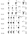
- Figur 1,
- einfarbiges Druckmuster mit räumlich konstant beabstandeten Rasterpunkten und schwach gedruckten Bereichen,
- Figur 2,
- Blockschaltbild zur Steuerung eines Thermotransferdruckers ,
- Figur 3a,
- Schaltungsanordnung mit Mitteln zum Bestimmen einer Verzögerung und zum Steuern des Hilfsimpulsgenerators,
- Figur 3b,
- Impuls/Zeit-Diagramme der Schaltungsanordnung,
- Figur 4a,
- Schaltungsanordnung für einen Hilfsimpulsgenerator,
- Figur 4b,
- Impuls/Zeit-Diagramm für Hilfsimpulse,
- Figur 5,
- Flussplan für ein Mittel zum Bestimmen einer Transportverzögerung und zum Steuern des Hilfsimpulsgenerators,
- Figur 6a,
- Impuls/Zeit-Diagramm für ein langsames Drucken einer Folge von Druckimpulsen (prior art),
- Figur 6b,
- Impuls/Zeit-Diagramm einer zugehörigen Encoderimpulsfolge,
- Figur 6c,
- Temperatur/Zeit-Diagramm an einem Heizelement für ein langsames Drucken einer Folge von Druckimpulsen,
- Figur 7a,
- Impuls/Zeit-Diagramm für ein schnelles Drucken einer Folge von Druckimpulsen im Idealfall,
- Figur 7b,
- Impuls/Zeit-Diagramm einer zugehörigen Encoderimpulsfolge,
- Figur 7c,
- Temperatur/Zeit-Diagramm an einem Heizelement für ein schnelles Drucken einer Folge von Druckimpulsen,
- Figur 7d,
- Pixel/Zeit-Diagramm für ein schnelles Drucken einer Folge von Druckbildpunkten,
- Figur 8a,
- Impuls/Zeit-Diagramm für ein schnelles Drucken einer Folge von Druckimpulsen und bei Transportverzögerung,
- Figur 8b,
- Impuls/Zeit-Diagramm einer zugehörigen Encoderimpulsfolge,
- Figur 8c,
- Temperatur/Zeit-Diagramm an einem Heizelement für ein schnelles Drucken einer Folge von Druckimpulsen und mit Kompensation der Wirkung, die durch die Transport-verzögerung verursacht wird,
- Figur 8d,
- Pixel/Zeit-Diagramm für ein schnelles Drucken einer Folge von Druckbildpunkten und bei Transportverzögerung,
- Figur 9a,
- Impuls/Zeit-Diagramm für eine Folge von Druckimpulsen und mit Kompensation der Wirkung, die durch die Transportverzögerung verursacht wird,
- Figur 9b,
- Impuls/Zeit-Diagramm einer zugehörigen Encoderimpulsfolge,
- Figur 9c,
- Temperatur/Zeit-Diagramm an einem Heizelement für eine Folge von Druckimpulsen und mit Kompensation der Wirkung, die durch die Transportverzögerung verursacht wird,
- Figur 9d,
- Pixel/Zeit-Diagramm für eine Folge von Druckbildpunkten bei Kompensation der Wirkung, die durch die Transportverzögerung verursacht wird,
- Figur 10a,
- Detail des Druckmusters nach Figur 1 für ein gleichmäßig langsames Drucken einer Folge von Druckbildpunkten durch ein Heizelement,
- Figur 10b,
- Detail des Druckmusters nach Figur 1 für ein gleichmäßig schnelles Drucken einer Folge von Druckbildpunkten durch ein Heizelement,
- Figur 10c,
- Detail des Druckmusters nach Figur 1 für ein gleichmäßig langsames Drucken einer Folge von eng benachbarten Druckbildpunkten durch ein Heizelement,
- Figur 10d,
- Detail des Druckmusters nach Figur 1 für ein gleichmäßig schnelles Drucken einer Folge von eng benachbarten Druckbildpunkten durch ein Heizelement,
- Figur 10e,
- Detail des Druckmusters nach Figur 1 für ein gleichmäßig schnelles Drucken einer zeitlich vorverzerrten Folge von eng benachbarten Druckbildpunkten durch ein Heizelement,
- Figur 10f,
- Detail des Druckmusters nach Figur 1 für ein ungleichmäßig schnelles Drucken einer Folge von eng benachbarten Druckbildpunkten durch ein Heizelement,
- Figur 10g,
- Detail des Druckmusters nach Figur 1 für ein ungleichmäßig schnelles Drucken einer Folge von eng benachbarten Druckbildpunkten durch ein Heizelement mit Kompensation der Wirkung durch einen verzögerten Encoderimpuls.
Es ist vorgesehen, dass eine Druckersteuerung 45 mit einer DMA-Steuerung 43, mit einer Pixeldatenbereitstelleinheit (40) und mit einem Hilfsimpulsgenerator 41 sowie dass die DMA-Steuerung 43 mit der Pixeldatenbereitstelleinheit 40 steuerungsmäßig verbunden sind. Die Pixeldatenbereitstelleinheit 40 ist über den BUS 5 und die Druckersteuerung 45 ist über den BUS 5 und über eine Steuerleitung 47 für ein Interruptsignal I direkt mit dem Mikroprozessor 6 verbunden. Die DMA-Steuerung 43 ist über eine Steuerleitung für DMA-Steuersignale DMAACK, DMAREQ mit dem Mikroprozessor 6 verbunden. Die Druckersteuerung 45 liefert via Ausgang Q1 ein Schiebetaktsignal (shift clock) an die Pixeldatenbereitstelleinheit 40 und an das Schieberegister 11. Die Druckersteuerung 45 liefert via Ausgang Q2 ein Latch-Signal an die Speicherlatcheinheit 12, zum Halten und Verriegeln der Daten. Die Druckersteuerung 45 liefert via Ausgang Q5 ein Startsignal an den Hilfsimpulsgenerator 41, dessen Ausgang Q6 ein Hilfsimpulssignal abgibt, das über eine logische ODER-Verknüpfung 42 mit einem Strobe-Signal logisch verknüpft ist, welches via Ausgang Q4 von der Druckersteuerung 45 geliefert wird. Der Ausgang der ODER-Verknüpfung 42 ist an einen Steuereingang der Treibereinheit 13 gelegt, über den Steuereingang können sowohl das Strobe-Signal als auch die Hilfsimpulse zugeführt werden, welche zur Ansteuerung der Thermodruckelemente des Thermotransferdruckkopfes die Schalter der Treibereinheit 13 schalten. Die Schalter können vorteilhaft als UND-Gatter oder als Transistoren ausgeführt werden. Jedem Schalter bzw. UND-Gatter oder Transistor sind jeweils ein Latch der Speicherlatcheinheit 12 zugeordnet, welches eine Information für ein Vorheiz- bzw. Druckerfordernis des jeweiligen Pixels übernimmt und mit dem Latch-Signal hält. Das von der Pixeldatenbereitstelleinheit 40 mit den seriellen Druckdaten beaufschlagte Serien/Parallel-Schieberegister 11 übergibt die Druckdaten in einer ersten Ansteuerphase an die Speicherlatcheinheit 12. In einer zweiten Ansteuerphase wird während eines Strobe-Impulses jedes durch die zugehörigen Latches der Speicherlatcheinheit 12 angesteuertes Gatter der Treibereinheit 13 auf Durchgang geschaltet und ein Heizstromimpuls an das jeweilige Thermodruckheizelement abgegeben. Die jeweiligen Thermodruckheizelemente, für die ein Vorheiz- bzw. Druckerfordernis vorliegt, werden unmittelbar durch Heizstromimpulse vorgewärmt, die in ihrer Impulshöhe und Impulsbreite an die benötigte Heizenergie angepasst sind.
Die gesamte Druckdatensteuerung 4 kann vorzugsweise mit einer anwendungsspezifischen Schaltung (ASIC) bzw. programmierbaren Logik, wie beispielsweise der FPGA der Serie Spartan-II 2,5V der Firma XILINX (www.xilinx.com) realisiert werden. Weitere Informationen über Field Programmable Gate Array Chips und damit in Zusammenhang stehende Techniken werden in Zusammenhang mit der Figur 3a gegeben.
Weiterhin kann die Schaltungsanordnung 450 mit herkömmlicher Technologie als festverdrahtete Schaltung von Logikgattern positiver und/oder negativer Logik realisiert werden.
Ist jedoch ein Encoderflankenwechsel erfolgt, dann wird auf einen Schritt 702 Rücksetzen des Zählers verzweigt. Danach wird wieder der vierte Abfrageschritt 707 erreicht. Ist die Antwort dann wieder nein, d.h. der Hilfsimpulsgenerator ist nicht aktiv, dann wird zum ersten Abfrageschritt 703 zurück verzweigt.
Bei einer Transportverzögerung wird jedoch kein Encoderflankenwechsel vor dem Erreichen eines vorbestimmten Zählerstandes bzw. Überlauf erfolgen. Dann ist die Antwort auf den ersten Abfrageschritt 703 nein und es wird wieder der zweite Abfrageschritt 704 erreicht. Wird nun ein CLK-Überlauf des Zählers bzw. das Überschreiten eines vorbestimmten Zählerstandes festgestellt, dann ist die Antwort ja und ein dritter Abfrageschritt 705 wird erreicht, um festzustellen, ob der Hilfsimpulsgenerator aktiv ist. Ist die Antwort nein, d.h. letzterer ist inaktiv, dann wird ein Schritt 706 erreicht und der Hilfsimpulsgenerator eingeschaltet. Anschließend wird zum ersten Abfrageschritt 703 zurück verzweigt.
Ist die auf den vierten Abfrageschritt 707 gegebene Antwort ja, d.h. letzterer ist aktiv, dann wird auf eine Schritt 708 zum Abschalten des Hilfsimpulsgenerators erreicht. Anschließend wird wieder zum ersten Abfrageschritt 703 zurück verzweigt.
Solche (nicht dargestellten) Vorheizimpulse gestatten aber nur den Wert der Betriebstemperatur υB wieder zu erreichen und führen nicht zum Drucken einen Dots.
Ein zu druckendes Pixel P1* bis Pn* ist die kleinste Dateneinheit, die ein Objekt in einer Computergrafik kennzeichnet und farbig (geschwärzt) dargestellt. Bei höheren Druckgeschwindigkeiten werden entsprechende Maßnahmen nicht nur zur Vorverzerrung des Druckmusters sondern auch der Zeitdauer des Pixels zum Druckens jedes einzelnen Dots ergriffen.
Die Figur 9c zeigt ein Temperatur/Zeit-Diagramm an einem Heizelement für eine Folge von zudruckenden Druckbildpunkten. Indem während des Druckens die Temperatur über den Temperaturgrenzwert υL nicht nur zwischen den Zeitpunkten t2 und t3 sondern außerdem zwischen den Zeitpunkten t3 und t4 sowie t4 und t5 durch zusätzliche Heizimpulse IH3' und IH4' angehoben wird, erfolgt eine Kompensation der Wirkung der Transportverzögerung.
Die durch einen Hauptheizimpuls und Hilfsheizimpulse bedingte wirksame Gesamtlänge der Druckimpulse wird über den vorgesehenen Rasterzeitpunkt hinaus verlängert, wenn ein Druckerfordernis vorliegt und eine Transportverzögerung festgestellt wird. Die Länge eines Druckimpulses ist dabei stets kleiner als der Abstand der Rasterzeitpunkte voneinander.
- des Widerstandswertes eines Thermodruckelementes
- von der Umgebungstemperatur
- von den Druckparametern festgelegt wird.
Via Thermotransferfarbband werden je ein Dot DI*, DII* und DIII* nacheinander in den Druckspalten CI*, CII* und CIII* aufgedruckt. Durch diese Maßnahme wird eine Verdopplung der Druckauflösung in Transportrichtung möglich, wobei aber Zeit für die Entzerrung der Dots in Transportrichtung zur Verfügung gestellt werden muß.
In einer weiteren Variante wird jedoch keine Entzerrung der Dots durchgeführt und die Transportgeschwindigkeit v geändert und beispielsweise verdoppelt auf 2v. Somit wird wieder ein Druckmusterdetail - wie in Fig.10a gezeigt - erreicht und die Verdopplung der Druckauflösung in Transportrichtung wird durch die auf 2v verdoppelte Transportgeschwindigkeit kompensiert.
In einer weiteren Variante wird jedoch keine Entzerrung der Dots durchgeführt und die Transportgeschwindigkeit v geändert und beispielsweise erhöht auf 1,5v. Somit wird wieder ein Druckmusterdetail - wie in Fig.10c gezeigt - erreicht und die Verbesserung der Druckauflösung in Transportrichtung durch eine Taktperiode des Wertes 2/3 T wird durch die auf 1,5v erhöhte Transportgeschwindigkeit kompensiert. Die in Fig.10c erzielte Verdoppelung der horizontalen Druckauflösung bleibt somit bei 1,5 facher Transportgeschwindigkeit erhalten.
Die vertikale Druckauflösung wird nun ebenfalls um den 1,5 fachen Wert erhöht, indem die Anzahl der Thermodruckheizelemente von 240 auf 360 in der Reihe 14 des Druckkopfes erhöht wird. Beim Drucken werden nur 305 Thermodruckheizelemente angesteuert, so dass die vertikale Druckauflösung 305 Dot per Inch beträgt.
Via Thermotransferfarbband werden je ein Dot D1*, D2*, D3* und Dn* nacheinander in den Druckspalten C1*, C2*, C3* und Cn* aufgedruckt. Im vorstehenden Beispiel wird nur in der Druckspalte C4* kein Dot gedruckt.
Es wird ein gleichmäßiges Druckmuster - wie prinzipiell in der Figur 1 im Feld 3 gezeigt ist - aber nur bei einem gleichmäßigen Transport von Poststücken erreicht.
Via Thermotransferfarbband werden je ein Dot D1', D2', D3' und Dn' nacheinander in den Druckspalten C1', C2', C3' und Cn' aufgedruckt. Im vorstehenden Beispiel wird wieder nur in der Druckspalte C4' kein Dot gedruckt. Anhand des Beispiels nach Figur 8 wurde die Wirkung der Transportverzögerung bereits erläutert. Der gedruckte Punkt D1' liegt neben der Druckspalten C1' und die Größe der Dots D2', D3' in den Druckspalten C2' und C3' werden werden in Transportrichtung (Pfeil) des Druckträgers (nicht dargestellt) gestaucht wiedergegeben.
Claims (15)
- Anordnung zur Ansteuerung eines Thermotransferdruckkopfes umfassend erste Mittel (45 bzw. 451, 452, 454) zum Bestimmen einer Transportverzögerung und zweite Mittel (41) zum Erzeugen von Hilfsheizimpulsen zur Erhaltung der Drucktemperatur an den Thermodruckheizelementen (1411 - 177x), wobei die ersten Mittel (45 bzw. 451, 452, 454) über die zweiten Mittel (41) mit dem Thermotransferdruckkopf (1) verbunden sind.
- Anordnung, nach Anspruch 1, gekennzeichnet dadurch, dass die ersten Mittel ein Logikgatter (451), einen Impulsgeber (452), einen Impulsfilter (453) und einen Taktgeber (454) zum Bestimmen einer Transportverzögerung und dass die zweite Mittel einen Hilfsimpulsgenerator (41) einschließen.
- Anordnung, nach Anspruch 1, gekennzeichnet dadurch, dass die ersten Mittel zum Bestimmen einer Transportverzögerung einen Zähler (4521), einen Flankenerkenner (4522) und eine Logik (4524) einschließen, wobei der Zähler (4521) eine Anzahl an Taktimpulsen eines Taktgebersignals solange zählt, bis der Zähler zurückgesetzt wird, wobei der Flankenerkenner (4522) unverzögerte und verzögerte Encoderimpulse (e1, e2) zu einer Encoderimpulsfolge aufbereitet, welche mit einem schmalen Impuls, die eine Encoderimpulsflanke bei jedem H/L- und L/H-Flankenwechsel kennzeichnet, den Zähler (4521) zurücksetzt und wobei die Logik (4524) zur Freigabe des Erzeugens von Hilfsheizimpulsen vorgesehen ist, wenn eine vorbestimmte Anzahl an gezählten Taktimpulsen überschritten wird bzw. ein Überlauf vor dem nächsten Encoderimpulsflankenwechsel erreicht ist.
- Anordnung, nach Anspruch 2, gekennzeichnet dadurch, dass der Impulsgeber (452) einen Heizimpulsgenerator (4523) aufweist und eingangsseitig mit den Encodersignalen, Taktgebersignal und einem Rücksetzsignal beaufschlagt wird und eine Encoderimpulsfolge an seinem ersten Ausgang (Q3), Strobeimpulse an seinem zweiten Ausgang (Q4) und einen Freigabeimpuls an seinem dritten Ausgang (Q5) bei einer Transportverzögerung liefert.
- Anordnung, nach den Ansprüchen 1 bis 4, gekennzeichnet dadurch, dass der Zähler (4521) mit seinem Rücksetzeingang an den Ausgang eines Logikgatters (451) geschaltet und mit seinem Takteingang mit einem Taktgeber (454) verbunden ist, dass das Logikgatter (451) an seinem einem Eingang mit einem Steuersignal (RST_CLK) und an seinem anderem Eingang mit einem aufbereiteten Encoderimpulssignal beaufschlagt wird, welches am Ausgang (Q7) des Impulsfilters (453) abgegeben wird, wobei der Eingang des Impulsfilters (453) an den Ausgang (Q3) des Flankenerkenners (4522) geschaltet ist und bei einem jeden Flankenwechsel der Encoderimpuse (e1 und e2) einen kurzen Impuls ab gibt, der zum Rücksetzen des Zählers bei einem jeden Flankenwechsel der Encoderimpuse verwendet wird..
- Anordnung, nach Anspruch 5, gekennzeichnet dadurch, dass der Taktgeber (454) einen vorgeteilten Takt und der Zähler (4521) an seinen Ausgängen (QA, QB, QC und QD) einen Binärcode für die Zahl der gezählten Taktimpuse seit einem Rücksetzen des Zählers abgibt.
- Anordnung, nach Anspruch 5, gekennzeichnet dadurch, dass das Logikgatter (451) ein NAND-Gatter ist und dass der Impulsfilters (453) ein analoges oder ein digitales Glied enthält, das Spikes und andere Störungen in der Encoderimpulsfolge unterdrückt.
- Anordnung, nach Anspruch 5, gekennzeichnet dadurch, dass ein Taktsignal eines Mikroprozessors (6) der Steuerung auf dem Mainboard verwendet wird und der Zähler (4521) und die Freigabelogik (4524) vom Mikroprozessor (6) umprogrammierbar ausgebildet sind sowie dass einige der Ausgangasignale des Zählers mit dem Taktgebersignal logisch verknüpft sind, um bei Bedarf und synchron zum Flankenwechsel der Encodersignale weitere Impulse zu erzeugen.
- Anordnung, nach Anspruch 2, gekennzeichnet dadurch, dass die ersten Mittel (451, 452, 453, 454) zum Bestimmen einer Transport-verzögerung und der Hilfsimpulsgenerator (41) Bestandteile einer Druckdatensteuerung (4) sind, wobei der Mikroprozessor (6) über die Druckdatensteuerung (4) mit dem Thermotransferdruckkopf (1) verbunden ist, wobei die vom Mikroprozessor (6) programmierbare Druckdatensteuerung (4) über einen Heizimpulsgenerator (4523) Strobe-Impulse und der Hilfsimpulsgenerator (41) Hilfsstrobe-Impulse als Heizimpulse auf die jeweilig zum Drucken angesteuerten Thermodruckheizelementen (1411 - 177x) des Thermotransferdruckkopfes (1) abgibt, wobei der Ausgang (Q4) des Heizimpulsgenerators (4523) und der Ausgang (Q6) des Hilfsimpulsgenerators (41) mit einem OR-Gatter (42) oder wobei der Heizimpulsgenerator (4523) und der Hilfsimpulsgenerator (41) ausgangsseitig über eine wired-OR-Verknüpfung (420) logisch miteinander verschaltet sind.
- Anordnung, nach Anspruch 9, gekennzeichnet dadurch, dass die ersten Mittel (451, 452, 453, 454) zum Bestimmen einer Transportverzögerung in einer Druckersteuerung (45) der Druckdatensteuerung (4) realisiert sind, die mit einem Encoder (3) verbunden ist, dass die Druckersteuerung (45) mit einer DMA-Steuerung (43), mit einer Pixeldatenbereitstelleinheit (40) und mit dem Hilfsimpulsgenerator (41) sowie dass die DMA-Steuerung (43) mit der Pixeldatenbereitstelleinheit (40) steuerungsmäßig verbunden sind, dass die Pixeldatenbereitstelleinheit (40) über einen BUS (5) und dass die Druckersteuerung (45) über den BUS (5) und über eine Steuerleitung (47) für ein Interruptsignal (I) direkt mit dem Mikroprozessor 6 verbunden sind sowie dass der Mikroprozessor (6) über den BUS (5) weiter mindestens mit einem Pixelspeicher (7), einem nichtflüchtiger Speicher (8) und einem Festwertspeicher (9) adress-, daten- und steuerungsmäßig verbunden ist.
- Verfahren zur Ansteuerung eines Thermotransferdruckkopfes umfassend die Schritte:Erzeugen von Hilfsheizimpulsen zur Aufrechterhaltung einer zum Drucken erforderlichen Temperatur an Thermodruckelementen für welche ein Druckerfordernis vorliegt.Bestimmen einer Transportverzögerung und
- Verfahren, nach Anspruch 11, gekennzeichnet dadurch, dass das Bestimmen einer Transportverzögerung anhand eines fehlenden Encoderflankenwechsel vor einem Überlauf des Zählers bzw. einem Überschreiten eines vorbestimmten Zählerstandes festgestellt wird.
- Verfahren, nach Anspruch 12, gekennzeichnet dadurch, dass nach einem Start (Schritt 701) ein Encoderflankenwechsel festgestellt wird (erster Abfrageschritt 703) und wenn letzterer noch nicht erfolgt ist, geprüft wird (zweiter Abfrageschritt 704), ob ein Überlauf des Zählers bzw. das Überschreiten eines vorbestimmten Zählerstandes erfolgt ist, wobei dann wenn letzteres nicht erfolgt ist, geprüft wird (vierter Abfrageschritt 707), ob ein Hilfsimpulsgenerator aktiv ist, wobei dann wenn letzterer nicht aktiv ist, zum Feststellen eines Encoderflankenwechsels (erster Abfrageschritt 703) zurück verzweigt wird und dann wenn ein Encoderflankenwechsel erfolgt ist, ein Rücksetzen des Zählers (Schritt 702) vorgenommen und dann geprüft wird, ob der Hilfsimpulsgenerator aktiv ist (vierter Abfrageschritt 707), wobei dann wenn der Hilfsimpulsgenerator nicht aktiv ist, wieder geprüft wird, ob ein Encoderflankenwechsel erfolgt ist (erster Abfrageschritt 703) und falls kein Encoderflankenwechsel erfolgt ist, geprüft wird (zweiter Abfrageschritt 704), ob ein Überlauf des Zählers bzw. das Überschreiten eines vorbestimmten Zählerstandes erfolgt ist, wobei dann wenn letzteres erfolgt ist, festgestellt wird (dritter Abfrageschritt 705), ob der Hilfsimpulsgenerator aktiv ist und wenn letzterer inaktiv ist, der Hilfsimpulsgenerator eingeschaltet wird (Schritt 706) und anschließend zurück verzweigt wird, um den Encoderflankenwechsel zu überprüfen (erster Abfrageschritt 703), wobei dann wenn der Hilfsimpulsgenerator aktiv ist (dritter Abfrageschritt 705) ebenfalls zurück verzweigt wird, um den Encoderflankenwechsel zu überprüfen (erster Abfrageschritt 703),
dass dann nach einem Rücksetzen des Zählers (Schritt 702) oder einem fehlenden Überlauf des Zählers bzw. fehlenden Überschreiten eines vorbestimmten Zählerstandes und falls der Hilfsimpulsgenerator noch aktiv ist (vierter Abfrageschritt 707) der Hilfsimpulsgenerator abgeschaltet wird (Schritt 708) und anschließend wieder (zum ersten Abfrageschritt 703) zurück verzweigt wird. - Verfahren, nach Anspruch 13, gekennzeichnet dadurch, dass die Länge der Druckimpulse oder die Länge der Pause zwischen den unmittelbar voneinander beabstandeten Druckimpulsen während des Druckens variabel ist und in Abhängigkeit:des Widerstandswertes eines Thermodruckelementesvon der Umgebungstemperaturvon den Druckparametern festgelegt wird.
- Verfahren, nach Anspruch 14, gekennzeichnet dadurch, dass die Druckimpulse Hilfsheizimpulse umfassen, wobei die Länge der Hilfsheizimpulse oder der Pause zwischen den Hilfsheizimpulsen in Abhängigkeit von mindestens einem der vorgenannten Parameter variabel ist und dass vom Mikroprozessor (6) mindestens vor jedem Einschalten des Hilfsheizimpulsgenerators (41 bzw. 4523) Einstelldaten übermittelt werden.
Applications Claiming Priority (2)
| Application Number | Priority Date | Filing Date | Title |
|---|---|---|---|
| DE102004027517 | 2004-06-03 | ||
| DE102004027517A DE102004027517B4 (de) | 2004-06-03 | 2004-06-03 | Anordnung und Verfahren zur Ansteuerung eines Thermotransferdruckkopfes |
Publications (2)
| Publication Number | Publication Date |
|---|---|
| EP1602495A1 true EP1602495A1 (de) | 2005-12-07 |
| EP1602495B1 EP1602495B1 (de) | 2009-10-21 |
Family
ID=34936016
Family Applications (1)
| Application Number | Title | Priority Date | Filing Date |
|---|---|---|---|
| EP05009546A Expired - Lifetime EP1602495B1 (de) | 2004-06-03 | 2005-04-30 | Anordnung und Verfahren zur Ansteuerung eines Thermotransferdruckkopfes |
Country Status (4)
| Country | Link |
|---|---|
| US (1) | US7256804B2 (de) |
| EP (1) | EP1602495B1 (de) |
| AT (1) | ATE446198T1 (de) |
| DE (2) | DE102004027517B4 (de) |
Families Citing this family (4)
| Publication number | Priority date | Publication date | Assignee | Title |
|---|---|---|---|---|
| DE102006009334A1 (de) * | 2006-03-01 | 2007-09-20 | Francotyp-Postalia Gmbh | Verfahren zur Qualitätsverbesserung des Druckens mit einem Thermotransferdruckkopf und Anordnung zur Durchführung des Verfahrens |
| JP4875127B2 (ja) * | 2009-09-28 | 2012-02-15 | パナソニック株式会社 | 三次元画像処理装置 |
| WO2016025003A1 (en) * | 2014-08-15 | 2016-02-18 | Hewlett-Packard Development Company, Lp | Alignment module used in printing |
| CN114347345B (zh) * | 2022-01-13 | 2024-03-26 | 山东明科电气技术有限公司 | 一种脉冲式热塑性复合材料制品成型装置及其使用方法 |
Citations (3)
| Publication number | Priority date | Publication date | Assignee | Title |
|---|---|---|---|---|
| US4705417A (en) * | 1985-01-19 | 1987-11-10 | Pa Consulting Services Limited | Postal franking machine |
| US5610649A (en) * | 1993-04-26 | 1997-03-11 | Fuji Photo Film Co., Ltd. | Color thermal printing method |
| US5838356A (en) * | 1995-03-07 | 1998-11-17 | Francotyp-Postalia Ag & Co. | Print head thermocontrol |
Family Cites Families (15)
| Publication number | Priority date | Publication date | Assignee | Title |
|---|---|---|---|---|
| JPS57151378A (en) * | 1981-03-16 | 1982-09-18 | Fuji Xerox Co Ltd | Driving system for heat-sensitive recording head |
| US4510507A (en) * | 1982-08-05 | 1985-04-09 | Canon Kabushiki Kaisha | Thermal recording apparatus |
| JPS609772A (ja) * | 1983-06-29 | 1985-01-18 | Fuji Xerox Co Ltd | 感熱記録方式 |
| GB2144081B (en) * | 1983-07-23 | 1987-10-28 | Pa Consulting Services | Postal franking machines |
| JPS63317362A (ja) * | 1987-06-19 | 1988-12-26 | Shinko Electric Co Ltd | サ−マルプリンタの印刷方法 |
| JPH02125763A (ja) * | 1988-07-01 | 1990-05-14 | Canon Inc | 記録方法及びその装置 |
| DE3833746A1 (de) * | 1988-09-30 | 1990-04-05 | Siemens Ag | Thermodruckverfahren mit vorheizung |
| DE4133207A1 (de) * | 1991-10-07 | 1993-04-15 | Francotyp Postalia Gmbh | Verfahren zum steuern der speisung eines thermodruck-heizelements |
| DE4221270A1 (de) * | 1992-06-26 | 1994-01-05 | Francotyp Postalia Gmbh | Anordnung und Verfahren zur Klischeetextteiländerung für Frankiermaschinen |
| DE59710554D1 (de) | 1996-01-31 | 2003-09-18 | Francotyp Postalia Ag | Frankiermaschine |
| DE19748954A1 (de) | 1997-10-29 | 1999-05-06 | Francotyp Postalia Gmbh | Verfahren für eine digital druckende Frankiermaschine zur Erzeugung und Überprüfung eines Sicherheitsabdruckes |
| DE29905219U1 (de) | 1999-03-12 | 1999-06-17 | Francotyp-Postalia AG & Co., 16547 Birkenwerder | Sicherheitsmodul mit Statussignalisierung |
| DE19928058B4 (de) | 1999-06-15 | 2005-10-20 | Francotyp Postalia Ag | Anordnung und Verfahren zur Generierung eines Sicherheitsabdruckes |
| DE19928061C2 (de) | 1999-06-15 | 2003-08-28 | Francotyp Postalia Ag | Sicherheitsmodul zur Überwachung der Systemsicherheit und Verfahren |
| DE20112350U1 (de) | 2001-07-16 | 2002-01-17 | Francotyp Postalia Gmbh | Anordnung zum Schutz eines Sicherheitsmoduls |
-
2004
- 2004-06-03 DE DE102004027517A patent/DE102004027517B4/de not_active Expired - Fee Related
-
2005
- 2005-04-30 AT AT05009546T patent/ATE446198T1/de active
- 2005-04-30 DE DE502005008360T patent/DE502005008360D1/de not_active Expired - Lifetime
- 2005-04-30 EP EP05009546A patent/EP1602495B1/de not_active Expired - Lifetime
- 2005-05-27 US US11/139,867 patent/US7256804B2/en not_active Expired - Fee Related
Patent Citations (3)
| Publication number | Priority date | Publication date | Assignee | Title |
|---|---|---|---|---|
| US4705417A (en) * | 1985-01-19 | 1987-11-10 | Pa Consulting Services Limited | Postal franking machine |
| US5610649A (en) * | 1993-04-26 | 1997-03-11 | Fuji Photo Film Co., Ltd. | Color thermal printing method |
| US5838356A (en) * | 1995-03-07 | 1998-11-17 | Francotyp-Postalia Ag & Co. | Print head thermocontrol |
Also Published As
| Publication number | Publication date |
|---|---|
| DE102004027517B4 (de) | 2007-05-10 |
| EP1602495B1 (de) | 2009-10-21 |
| US20050270360A1 (en) | 2005-12-08 |
| DE502005008360D1 (de) | 2009-12-03 |
| ATE446198T1 (de) | 2009-11-15 |
| US7256804B2 (en) | 2007-08-14 |
| DE102004027517A1 (de) | 2005-12-29 |
Similar Documents
| Publication | Publication Date | Title |
|---|---|---|
| EP0921008B1 (de) | Verfahren zum Toleranzausgleich bei einem Tintendruckkopf | |
| DE102005007220B4 (de) | Verfahren und Anordnung zum Steuern des Druckens eines Thermotransferdruckgeräts | |
| DE2501793C2 (de) | Druckmaschine | |
| EP0331138B1 (de) | Drucker | |
| EP0352498A1 (de) | Frankiermaschine | |
| EP0716398A2 (de) | Frankiermaschineninterne Schnittstellenschaltung und Verfahren zur manipulationssicheren Druckdatensteuerung | |
| EP1829692B1 (de) | Verfahren zur Qualitätsverbesserung des Druckens mit einem Thermotransferdruckkopf und Anordnung zur Durchführung des Verfahrens | |
| DE102007040402B4 (de) | Verfahren zur Registerkorrektur bei Papierschrumpfung | |
| DE3873214T2 (de) | Steuerschaltung fuer thermisches drucken. | |
| EP1416430A2 (de) | Anordnung zum Drucken eines Druckbildes mit Bereichen unterschiedlicher Druckbildauflösung | |
| EP1602495B1 (de) | Anordnung und Verfahren zur Ansteuerung eines Thermotransferdruckkopfes | |
| DE4337542C2 (de) | Anordnung für eine ETR-Druckkopfansteuerung | |
| EP1378820B1 (de) | Anordnung zum Steuern des Druckens in einem Postbearbeitungsgerät | |
| DE102011000220B4 (de) | Verfahren und Druckgerät zum Drucken zeilenweise gruppierter Bildinformation auf einen Aufzeichnungsträger | |
| DE19755873C2 (de) | Anordnung zum Toleranzausgleich bei einem Tintendruckkopf | |
| DE4115705C2 (de) | Bilddatenkorrektureinrichtung | |
| EP1661716B1 (de) | Verfahren zum Ansteuern eines Thermotransferdruckkopfes | |
| EP0583622B1 (de) | Thermo-Transfer-Druckeinrichtung | |
| EP0575668B1 (de) | Ansteuerschaltung für eine elektrothermische Druckvorrichtung mit Widerstandsband | |
| EP1661717B1 (de) | Verfahren zum Ansteuern eines Thermotransferdruckkopfes | |
| EP1950043B1 (de) | Verfahren zum Ansteuern eines Thermotransferdruckkopfes | |
| DE69617153T2 (de) | Integrierte fehlertoleranz in druckmechanismen | |
| DE102007022796A1 (de) | Verfahren zum Ansteuern eines Thermotransferdruckkopfes | |
| EP2056257A1 (de) | Reduktion von Abstandsfehlern zwischen Punkten eines Druckbildes | |
| EP1491347B1 (de) | Verfahren und Anordnung zur Reduzierung von Druckerfehlen während des Drukens in einem Postbearbeitungsgerät |
Legal Events
| Date | Code | Title | Description |
|---|---|---|---|
| PUAI | Public reference made under article 153(3) epc to a published international application that has entered the european phase |
Free format text: ORIGINAL CODE: 0009012 |
|
| AK | Designated contracting states |
Kind code of ref document: A1 Designated state(s): AT BE BG CH CY CZ DE DK EE ES FI FR GB GR HU IE IS IT LI LT LU MC NL PL PT RO SE SI SK TR |
|
| AX | Request for extension of the european patent |
Extension state: AL BA HR LV MK YU |
|
| RAP1 | Party data changed (applicant data changed or rights of an application transferred) |
Owner name: FRANCOTYP-POSTALIA GMBH |
|
| 17P | Request for examination filed |
Effective date: 20060111 |
|
| AKX | Designation fees paid |
Designated state(s): AT BE BG CH CY CZ DE DK EE ES FI FR GB GR HU IE IS IT LI LT LU MC NL PL PT RO SE SI SK TR |
|
| 17Q | First examination report despatched |
Effective date: 20071106 |
|
| GRAP | Despatch of communication of intention to grant a patent |
Free format text: ORIGINAL CODE: EPIDOSNIGR1 |
|
| GRAS | Grant fee paid |
Free format text: ORIGINAL CODE: EPIDOSNIGR3 |
|
| GRAA | (expected) grant |
Free format text: ORIGINAL CODE: 0009210 |
|
| AK | Designated contracting states |
Kind code of ref document: B1 Designated state(s): AT BE BG CH CY CZ DE DK EE ES FI FR GB GR HU IE IS IT LI LT LU MC NL PL PT RO SE SI SK TR |
|
| REG | Reference to a national code |
Ref country code: GB Ref legal event code: FG4D Free format text: NOT ENGLISH |
|
| REG | Reference to a national code |
Ref country code: CH Ref legal event code: EP |
|
| REG | Reference to a national code |
Ref country code: IE Ref legal event code: FG4D |
|
| REF | Corresponds to: |
Ref document number: 502005008360 Country of ref document: DE Date of ref document: 20091203 Kind code of ref document: P |
|
| LTIE | Lt: invalidation of european patent or patent extension |
Effective date: 20091021 |
|
| PG25 | Lapsed in a contracting state [announced via postgrant information from national office to epo] |
Ref country code: PT Free format text: LAPSE BECAUSE OF FAILURE TO SUBMIT A TRANSLATION OF THE DESCRIPTION OR TO PAY THE FEE WITHIN THE PRESCRIBED TIME-LIMIT Effective date: 20100222 Ref country code: IS Free format text: LAPSE BECAUSE OF FAILURE TO SUBMIT A TRANSLATION OF THE DESCRIPTION OR TO PAY THE FEE WITHIN THE PRESCRIBED TIME-LIMIT Effective date: 20100221 Ref country code: LT Free format text: LAPSE BECAUSE OF FAILURE TO SUBMIT A TRANSLATION OF THE DESCRIPTION OR TO PAY THE FEE WITHIN THE PRESCRIBED TIME-LIMIT Effective date: 20091021 Ref country code: FI Free format text: LAPSE BECAUSE OF FAILURE TO SUBMIT A TRANSLATION OF THE DESCRIPTION OR TO PAY THE FEE WITHIN THE PRESCRIBED TIME-LIMIT Effective date: 20091021 Ref country code: SE Free format text: LAPSE BECAUSE OF FAILURE TO SUBMIT A TRANSLATION OF THE DESCRIPTION OR TO PAY THE FEE WITHIN THE PRESCRIBED TIME-LIMIT Effective date: 20091021 Ref country code: ES Free format text: LAPSE BECAUSE OF FAILURE TO SUBMIT A TRANSLATION OF THE DESCRIPTION OR TO PAY THE FEE WITHIN THE PRESCRIBED TIME-LIMIT Effective date: 20100201 |
|
| REG | Reference to a national code |
Ref country code: IE Ref legal event code: FD4D |
|
| PG25 | Lapsed in a contracting state [announced via postgrant information from national office to epo] |
Ref country code: PL Free format text: LAPSE BECAUSE OF FAILURE TO SUBMIT A TRANSLATION OF THE DESCRIPTION OR TO PAY THE FEE WITHIN THE PRESCRIBED TIME-LIMIT Effective date: 20091021 Ref country code: SI Free format text: LAPSE BECAUSE OF FAILURE TO SUBMIT A TRANSLATION OF THE DESCRIPTION OR TO PAY THE FEE WITHIN THE PRESCRIBED TIME-LIMIT Effective date: 20091021 |
|
| PG25 | Lapsed in a contracting state [announced via postgrant information from national office to epo] |
Ref country code: RO Free format text: LAPSE BECAUSE OF FAILURE TO SUBMIT A TRANSLATION OF THE DESCRIPTION OR TO PAY THE FEE WITHIN THE PRESCRIBED TIME-LIMIT Effective date: 20091021 Ref country code: EE Free format text: LAPSE BECAUSE OF FAILURE TO SUBMIT A TRANSLATION OF THE DESCRIPTION OR TO PAY THE FEE WITHIN THE PRESCRIBED TIME-LIMIT Effective date: 20091021 Ref country code: DK Free format text: LAPSE BECAUSE OF FAILURE TO SUBMIT A TRANSLATION OF THE DESCRIPTION OR TO PAY THE FEE WITHIN THE PRESCRIBED TIME-LIMIT Effective date: 20091021 Ref country code: IE Free format text: LAPSE BECAUSE OF FAILURE TO SUBMIT A TRANSLATION OF THE DESCRIPTION OR TO PAY THE FEE WITHIN THE PRESCRIBED TIME-LIMIT Effective date: 20091021 Ref country code: BG Free format text: LAPSE BECAUSE OF FAILURE TO SUBMIT A TRANSLATION OF THE DESCRIPTION OR TO PAY THE FEE WITHIN THE PRESCRIBED TIME-LIMIT Effective date: 20100121 |
|
| PLBE | No opposition filed within time limit |
Free format text: ORIGINAL CODE: 0009261 |
|
| STAA | Information on the status of an ep patent application or granted ep patent |
Free format text: STATUS: NO OPPOSITION FILED WITHIN TIME LIMIT |
|
| PG25 | Lapsed in a contracting state [announced via postgrant information from national office to epo] |
Ref country code: SK Free format text: LAPSE BECAUSE OF FAILURE TO SUBMIT A TRANSLATION OF THE DESCRIPTION OR TO PAY THE FEE WITHIN THE PRESCRIBED TIME-LIMIT Effective date: 20091021 Ref country code: CZ Free format text: LAPSE BECAUSE OF FAILURE TO SUBMIT A TRANSLATION OF THE DESCRIPTION OR TO PAY THE FEE WITHIN THE PRESCRIBED TIME-LIMIT Effective date: 20091021 |
|
| 26N | No opposition filed |
Effective date: 20100722 |
|
| PG25 | Lapsed in a contracting state [announced via postgrant information from national office to epo] |
Ref country code: GR Free format text: LAPSE BECAUSE OF FAILURE TO SUBMIT A TRANSLATION OF THE DESCRIPTION OR TO PAY THE FEE WITHIN THE PRESCRIBED TIME-LIMIT Effective date: 20100122 |
|
| BERE | Be: lapsed |
Owner name: FRANCOTYP-POSTALIA G.M.B.H. Effective date: 20100430 |
|
| PG25 | Lapsed in a contracting state [announced via postgrant information from national office to epo] |
Ref country code: MC Free format text: LAPSE BECAUSE OF NON-PAYMENT OF DUE FEES Effective date: 20100430 |
|
| PG25 | Lapsed in a contracting state [announced via postgrant information from national office to epo] |
Ref country code: BE Free format text: LAPSE BECAUSE OF NON-PAYMENT OF DUE FEES Effective date: 20100430 |
|
| PG25 | Lapsed in a contracting state [announced via postgrant information from national office to epo] |
Ref country code: CY Free format text: LAPSE BECAUSE OF FAILURE TO SUBMIT A TRANSLATION OF THE DESCRIPTION OR TO PAY THE FEE WITHIN THE PRESCRIBED TIME-LIMIT Effective date: 20091021 |
|
| PG25 | Lapsed in a contracting state [announced via postgrant information from national office to epo] |
Ref country code: LU Free format text: LAPSE BECAUSE OF NON-PAYMENT OF DUE FEES Effective date: 20100430 Ref country code: HU Free format text: LAPSE BECAUSE OF FAILURE TO SUBMIT A TRANSLATION OF THE DESCRIPTION OR TO PAY THE FEE WITHIN THE PRESCRIBED TIME-LIMIT Effective date: 20100422 |
|
| PG25 | Lapsed in a contracting state [announced via postgrant information from national office to epo] |
Ref country code: TR Free format text: LAPSE BECAUSE OF FAILURE TO SUBMIT A TRANSLATION OF THE DESCRIPTION OR TO PAY THE FEE WITHIN THE PRESCRIBED TIME-LIMIT Effective date: 20091021 |
|
| REG | Reference to a national code |
Ref country code: DE Ref legal event code: R084 Ref document number: 502005008360 Country of ref document: DE |
|
| REG | Reference to a national code |
Ref country code: DE Ref legal event code: R084 Ref document number: 502005008360 Country of ref document: DE Effective date: 20130125 |
|
| REG | Reference to a national code |
Ref country code: GB Ref legal event code: 746 Effective date: 20130319 |
|
| REG | Reference to a national code |
Ref country code: DE Ref legal event code: R081 Ref document number: 502005008360 Country of ref document: DE Owner name: FRANCOTYP-POSTALIA GMBH, DE Free format text: FORMER OWNER: FRANCOTYP-POSTALIA GMBH, 16547 BIRKENWERDER, DE Effective date: 20150330 |
|
| REG | Reference to a national code |
Ref country code: FR Ref legal event code: PLFP Year of fee payment: 12 |
|
| REG | Reference to a national code |
Ref country code: FR Ref legal event code: PLFP Year of fee payment: 13 |
|
| REG | Reference to a national code |
Ref country code: FR Ref legal event code: PLFP Year of fee payment: 14 |
|
| PGFP | Annual fee paid to national office [announced via postgrant information from national office to epo] |
Ref country code: GB Payment date: 20180321 Year of fee payment: 14 |
|
| PGFP | Annual fee paid to national office [announced via postgrant information from national office to epo] |
Ref country code: NL Payment date: 20180418 Year of fee payment: 14 |
|
| PGFP | Annual fee paid to national office [announced via postgrant information from national office to epo] |
Ref country code: DE Payment date: 20180314 Year of fee payment: 14 Ref country code: CH Payment date: 20180419 Year of fee payment: 14 |
|
| PGFP | Annual fee paid to national office [announced via postgrant information from national office to epo] |
Ref country code: FR Payment date: 20180420 Year of fee payment: 14 Ref country code: IT Payment date: 20180423 Year of fee payment: 14 Ref country code: AT Payment date: 20180419 Year of fee payment: 14 |
|
| REG | Reference to a national code |
Ref country code: DE Ref legal event code: R119 Ref document number: 502005008360 Country of ref document: DE |
|
| REG | Reference to a national code |
Ref country code: CH Ref legal event code: PL |
|
| REG | Reference to a national code |
Ref country code: NL Ref legal event code: MM Effective date: 20190501 |
|
| REG | Reference to a national code |
Ref country code: AT Ref legal event code: MM01 Ref document number: 446198 Country of ref document: AT Kind code of ref document: T Effective date: 20190430 |
|
| GBPC | Gb: european patent ceased through non-payment of renewal fee |
Effective date: 20190430 |
|
| PG25 | Lapsed in a contracting state [announced via postgrant information from national office to epo] |
Ref country code: DE Free format text: LAPSE BECAUSE OF NON-PAYMENT OF DUE FEES Effective date: 20191101 Ref country code: NL Free format text: LAPSE BECAUSE OF NON-PAYMENT OF DUE FEES Effective date: 20190501 Ref country code: LI Free format text: LAPSE BECAUSE OF NON-PAYMENT OF DUE FEES Effective date: 20190430 Ref country code: AT Free format text: LAPSE BECAUSE OF NON-PAYMENT OF DUE FEES Effective date: 20190430 Ref country code: CH Free format text: LAPSE BECAUSE OF NON-PAYMENT OF DUE FEES Effective date: 20190430 Ref country code: GB Free format text: LAPSE BECAUSE OF NON-PAYMENT OF DUE FEES Effective date: 20190430 |
|
| PG25 | Lapsed in a contracting state [announced via postgrant information from national office to epo] |
Ref country code: FR Free format text: LAPSE BECAUSE OF NON-PAYMENT OF DUE FEES Effective date: 20190430 |
|
| PG25 | Lapsed in a contracting state [announced via postgrant information from national office to epo] |
Ref country code: IT Free format text: LAPSE BECAUSE OF NON-PAYMENT OF DUE FEES Effective date: 20190430 |