EP1602445B1 - Procédé, outil et machine d'usinage pour la fabrication d'éléments de prothèse dentaire - Google Patents
Procédé, outil et machine d'usinage pour la fabrication d'éléments de prothèse dentaire Download PDFInfo
- Publication number
- EP1602445B1 EP1602445B1 EP05104707A EP05104707A EP1602445B1 EP 1602445 B1 EP1602445 B1 EP 1602445B1 EP 05104707 A EP05104707 A EP 05104707A EP 05104707 A EP05104707 A EP 05104707A EP 1602445 B1 EP1602445 B1 EP 1602445B1
- Authority
- EP
- European Patent Office
- Prior art keywords
- tool
- machining
- coating
- radius
- forward face
- Prior art date
- Legal status (The legal status is an assumption and is not a legal conclusion. Google has not performed a legal analysis and makes no representation as to the accuracy of the status listed.)
- Active
Links
- 238000000034 method Methods 0.000 title claims description 27
- 238000004519 manufacturing process Methods 0.000 title claims description 7
- 239000004053 dental implant Substances 0.000 title 1
- 238000003754 machining Methods 0.000 claims abstract description 46
- 230000007423 decrease Effects 0.000 claims abstract description 7
- 238000000576 coating method Methods 0.000 claims description 36
- 239000011248 coating agent Substances 0.000 claims description 30
- 230000007704 transition Effects 0.000 claims description 16
- 238000000227 grinding Methods 0.000 claims description 8
- 239000002245 particle Substances 0.000 claims 4
- 230000001747 exhibiting effect Effects 0.000 claims 1
- 239000000463 material Substances 0.000 description 12
- 239000006061 abrasive grain Substances 0.000 description 5
- 238000007667 floating Methods 0.000 description 4
- 230000000694 effects Effects 0.000 description 2
- 238000005259 measurement Methods 0.000 description 2
- 239000003082 abrasive agent Substances 0.000 description 1
- 230000002411 adverse Effects 0.000 description 1
- 238000005452 bending Methods 0.000 description 1
- 238000005422 blasting Methods 0.000 description 1
- 238000010276 construction Methods 0.000 description 1
- 238000005520 cutting process Methods 0.000 description 1
- 238000000354 decomposition reaction Methods 0.000 description 1
- 230000006735 deficit Effects 0.000 description 1
- 238000003801 milling Methods 0.000 description 1
- 239000002994 raw material Substances 0.000 description 1
- 230000000284 resting effect Effects 0.000 description 1
Images
Classifications
-
- B—PERFORMING OPERATIONS; TRANSPORTING
- B24—GRINDING; POLISHING
- B24D—TOOLS FOR GRINDING, BUFFING OR SHARPENING
- B24D7/00—Bonded abrasive wheels, or wheels with inserted abrasive blocks, designed for acting otherwise than only by their periphery, e.g. by the front face; Bushings or mountings therefor
- B24D7/18—Wheels of special form
-
- A—HUMAN NECESSITIES
- A61—MEDICAL OR VETERINARY SCIENCE; HYGIENE
- A61C—DENTISTRY; APPARATUS OR METHODS FOR ORAL OR DENTAL HYGIENE
- A61C13/00—Dental prostheses; Making same
- A61C13/0003—Making bridge-work, inlays, implants or the like
-
- A—HUMAN NECESSITIES
- A61—MEDICAL OR VETERINARY SCIENCE; HYGIENE
- A61C—DENTISTRY; APPARATUS OR METHODS FOR ORAL OR DENTAL HYGIENE
- A61C13/00—Dental prostheses; Making same
- A61C13/0003—Making bridge-work, inlays, implants or the like
- A61C13/0004—Computer-assisted sizing or machining of dental prostheses
Definitions
- the invention relates to a method and a tool for the production of Zahnersatzeilen by transverse side processing and longitudinal feed machining, according to the preamble of claim 1 and 7, respectively.
- processing machines and tools are known with which a blank is milling and / or grinding processed.
- the grinding tools used therein have cylindrical surfaces and there may be a cone tip with a tip radius.
- DE 40 30 176 A1 describes a method for calibrating a motor-driven tool in a processing machine.
- the processing machine uses as a tool a cylindrical finger grinder.
- the tools used for the production of dental prostheses must be able to adapt eg a dental crown accurately to the geometry of the jaw or to replicate a complex tooth surface in all details in the case of a tooth replacement part.
- a lot of material must be removed from a blank on the one hand, but it often happens that narrow recesses must be worked out.
- tools are often used which have a comparatively sharp shape, eg that of a long cone.
- processing tools have several disadvantages. Firstly, in order to achieve high precision, the processing machines must be calibrated at regular intervals. The machining tools are subject to natural wear and the exact shape of the tool must be included in the calibration. Especially with machining tools with only oblique contours, an exact measurement of the tool proves to be very difficult.
- the present invention is therefore based on the object over the above-mentioned disadvantages in the processing of dental prostheses with such tools and a method, a processing machine and a To provide a tool that allows a high-precision machining with as few tool changes and long life of the tools used.
- dental prosthesis parts are processed in a processing machine with a method that uses a tool for Querlism- and longitudinal feed machining.
- the tool has graded areas having different diameters, each having a lateral surface for transverse side machining and in each case one end face for longitudinal feed machining, the diameter of the stepped areas becoming smaller towards the end face.
- both machining in the transverse direction to the tool axis and in the longitudinal direction of the tool axis can be on the one hand due to the slender tool tip sufficiently fine structures work out and on the other hand produce a large material removal, the leadership of the tool is improved, which thus Increased precision leads to faster processing.
- the processing is essentially carried out by grinding the blank. This makes it possible to work even high-strength materials, such as those often used in dentistry.
- the diameter of the tool used in each of the stepped areas is constant. This facilitates on the one hand the measurement of the tool for determining the wear and for determining the position of the tool outer contour and also the disadvantages already mentioned, which often occur when using tools with inclined working surfaces, are avoided.
- the diameter of the stepped areas decreases towards the end side in such a way that the envelope of the tool describes a cone which has an opening angle between 4 and 20 degrees.
- the envelope of the tool describes a cone which has an opening angle between 4 and 20 degrees.
- a particularly advantageous further development of the method relates to the use of a tool which has a coating containing abrasive grains. This allows the tool to be optimized in terms of functionality and durability. Such coatings have long been state of the art and are effective.
- the coating is designed differently in different areas of the tool. For example, there may be areas where, for example, there is a coarse coating for high material removal, and there are other areas with a fine coating for precise machining of the dental prosthesis. It is particularly advantageous if the grain size is different in different areas. Thus, the above-described advantageous division between coarse and less coarse grinding areas can be achieved.
- the layer thickness of the coating can also be adapted to the wear during machining by producing a greater layer thickness in regions of increased wear.
- the process can be carried out at least until the coating of the tool has worn to half the original thickness or more. This can be achieved on the one hand a constant material processing and on the other hand a long life of the tool.
- the wear can be corrected by calibrating the machine tool.
- the tool has stepped portions having different diameters, each having a lateral surface for transverse side machining and each having an end face for longitudinal feed machining, the diameter of the stepped portions becoming smaller towards the end face.
- the diameter of the tool in the stepped areas is constant in each case and decreases towards the front side so that the envelope describes a cone having an opening angle between 4 and 20 degrees.
- the tool has a transition from the end-side lateral surface with a first radius to the end face with a second radius smaller than the first radius to a predetermined surface, which also has a curvature smaller than the first radius according to a third radius.
- a spherical or lens-shaped end instead of a flat front side with a transition to the lateral surfaces is mentioned here.
- the transition may preferably have a horizontal surface, which may be regarded as an annular flat front side.
- the end face has a conical tip, which has a cone angle of 30 ° to 60 °, in particular of 45 °.
- the cone tip thus runs within the envelope. With such a tip, it is possible to work out fine structures such as fissures on the tooth without significantly affecting the effect of the floating of the tool.
- a particularly advantageous further development of the method relates to the use of a tool which has a coating. This allows the tool to be optimized in terms of functionality and durability.
- the coating is designed differently in different areas of the tool. For example, there may be areas where, for example, there is a coarse coating for high material removal, and there are other areas with a fine coating for high precision machining of the dental prosthesis.
- the coating contains abrasive grains.
- the coating can be worn during processing at least to half the original thickness.
- the wear can be corrected by calibrating the machine tool. This allows long service life and economical use of the tool for performing the method.
- the processing machine for carrying out the method using the tool according to one of claims 7 to 16 has a control adapted to the tool and the method.
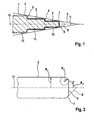
- FIG. 1 shows a cross section through a rotationally symmetrical tool 1 for carrying out the method according to the invention in a processing machine according to the invention, as shown in Fig. 3.
- a plurality of cylindrical side surfaces 2, 3, 4 are provided, whose length and respective radius difference are coordinated so that their edges form a conical envelope 5 at an angle ⁇ from here about 18 °.
- Cylinder grinders are most commonly used with a cone angle of approximately 4 °, the relatively large cone angle shown here serves above all the better representability.
- an end face 6 is provided at the top of the tool 1.
- the transition from the front side 6 to the first side surface 2 has a defined transition 7, which is seen here in cross-section circular.
- the surface of the tool 1 consists of various coatings 10, 11, 12, which can be applied by known methods on the raw material of the tool.
- the coatings 10, 11, 12 contain different grain sizes of the abrasive grains, which become coarser with increasing tool diameter.
- the coating 10 is thus suitable for fine finishing and for working out fine contours, whereas the coating 12 achieved a higher material removal. It is particularly advantageous to use a cone tip 6 '.
- FIG. 2 shows a section of FIG. 1 in order to more precisely illustrate the geometric relationships of the transition from the end face 6 to the first lateral surface 2.
- the lateral surface 2 lies on a radius R 1 and the end face 6 extends over a radius R 2 , so that there is a circular planar region.
- the transition 7 has a curvature with a radius R 3 , which is dimensioned such that a tangential connection to the end face 6 and the first shell 2 is formed. This is not mandatory and the radius R 3 can also be chosen so that no tangential connection of the transition 7 is formed, but rather an edge is formed, which may also be formed as a radius.
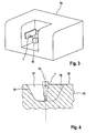
- FIG. 3 shows a processing machine 14 according to the invention.
- a tool 1 and a workpiece 15 are held adjustable relative to each other, so that the desired contour can be worked out with the tool 1 from the workpiece 15.
- Fig. 4 shows the tool 1 in the processing of the workpiece 15 in detail. Due to the lateral surfaces arranged substantially exclusively radially and perpendicular to the longitudinal axis 13 of the tool, the machining of the workpiece 15 can be completely decomposed into the components lateral and longitudinal feed machining. If the tool is moved in accordance with these components, this allows an approximate rectification of tool feed and force. This rectification is not given, for example, in a conical grinder due to its lateral surface with simultaneously existing longitudinal and transverse portions, which leads to the adverse effects already described above, in particular for floating.
- the feed is of an order of magnitude that is within the extension of the cutting edges, i. in a coating with abrasive grains, e.g. 60 microns protrude from the base material of the coating, the feed can be 10 microns, so only the sixth part thereof. It is readily understood that this feed can be realized under such conditions without a relevant impairment of accuracy occurs. When using a coating whose abrasive grains protrude only 10 microns, however, the feed would probably be reduced.
- the tool can be controlled so that the feed for the next processing step exclusively as a longitudinal feed, if this is greater than the intended cross feed.
- the processing plan is designed so that the proportion of transverse side machining is maximized, since on the cylindrical lateral surfaces 2, 3, 4 substantially more abrasive material is present in than at the comparatively small end faces 6, 8, 9 (FIG. 1).
- the tool 1 first enters the workpiece 15 with the end face 6. Depending on the machining depth, the other end faces 8, 9 (FIG. 1) engage the workpiece 15. After reaching the required depth, the tool 1 then works laterally, using the lateral surfaces 2, 3, 4 (FIG. 1), out of the depression 17 along the desired contour 18, without the end faces 6, 8, 9 (FIG be charged. Due to the shape of the tool, the opposite flanks of such a recess 17 can have at most the same angle ⁇ of the envelope of the tool.
- the coatings 10 - 12 of the lateral surfaces 2-4 shown in FIG. 1 are designed so that a coarse machining takes place with the lateral surfaces 3, 4, whereas a fine machining takes place with the lateral surface 2.
- the coating 10 can have a greater thickness may be formed as the coatings 11, 12 and for example, double-layered or multi-layered. This of course also applies to the coating on the end faces 6, 8 or 9 or at the transition 7 and the corresponding transitions from the end faces 8, 9 to the lateral surfaces 11,12.
Landscapes
- Health & Medical Sciences (AREA)
- Oral & Maxillofacial Surgery (AREA)
- Dentistry (AREA)
- Epidemiology (AREA)
- Life Sciences & Earth Sciences (AREA)
- Animal Behavior & Ethology (AREA)
- General Health & Medical Sciences (AREA)
- Public Health (AREA)
- Veterinary Medicine (AREA)
- Engineering & Computer Science (AREA)
- Mechanical Engineering (AREA)
- Dental Tools And Instruments Or Auxiliary Dental Instruments (AREA)
- Dental Prosthetics (AREA)
Claims (17)
- Procédé de fabrication de prothèses dentaires dans une machine d'usinage (14) comprenant un outil (1) pour l'usinage latéral transversal et pour l'usinage par avance longitudinale, caractérisé en ce que l'on utilise un outil (1) avec des parties échelonnées présentant différents diamètres avec une surface d'enveloppe respective (2, 3, 4) pour l'usinage latéral transversal et avec une surface frontale respective (6, 8, 9) pour l'usinage par avance longitudinale, le diamètre des régions échelonnées (2, 3, 4) diminuant en direction du côté frontal (6).
- Procédé selon la revendication 1, caractérisé en ce que l'usinage s'effectue par meulage.
- Procédé selon la revendication 1 ou 2, caractérisé en ce que le diamètre de l'outil (1) dans les régions échelonnées (2, 3, 4) reste à chaque fois constant.
- Procédé selon l'une quelconque des revendications 1 à 3, caractérisé en ce que le diamètre des régions échelonnées (2, 3, 4) diminue vers un côté frontal (6) de telle sorte que l'extrémité d'enveloppement (5) décrive un cône qui présente un angle d'ouverture (α) compris entre 4 et 20 degrés.
- Procédé selon l'une quelconque des revendications 2 à 4, caractérisé en ce que l'usinage s'effectue avec un revêtement (10, 11, 12) contenant des grains abrasifs, la taille des grains du revêtement (10, 11, 12) étant différente dans au moins deux régions différentes (2, 3, 4, 6, 8, 9).
- Procédé selon l'une quelconque des revendications 1 à 5, caractérisé en ce que l'on effectue en même temps au moyen de la surface frontale (6) et de la surface d'enveloppe adjacente (2) à la pointe de l'outil un usinage fine et au moyen de la surface frontale (8, 9) espacée de la pointe de l'outil et/ou de la surface d'enveloppe (3, 4), un usinage grossier.
- Outil (1) pour l'usinage de pièces pour la fabrication de prothèses dentaires au moyen d'usinage latéral transversal et d'usinage par avance longitudinale, caractérisé en ce que l'outil (1) présente des régions échelonnées de différents diamètres avec à chaque fois une surface d'enveloppe (2, 3, 4) pour l'usinage latéral transversal et une surface frontale (6, 8, 9) pour l'usinage par avance longitudinale, le diamètre des régions échelonnées (2, 3, 4) diminuant vers la surface frontale (6).
- Outil (1) selon la revendication 7, caractérisé en ce que le diamètre de l'outil dans les régions échelonnées (2, 3, 4) reste à chaque fois constant.
- Outil (1) selon la revendication 7 ou 8, caractérisé en ce que le diamètre des régions échelonnées (2, 3, 4) diminue vers le côté frontal (6) de telle sorte que l'extrémité d'enveloppement (5) décrive un cône qui présente un angle d'ouverture (α) compris entre 4 et 20 degrés.
- Outil (1) selon l'une quelconque des revendications 7 à 9, caractérisé en ce qu'avec l'outil (1), la transition (7) de la surface d'enveloppe du côté frontal (2) avec un premier rayon (R1) au côté frontal (6) avec un deuxième rayon (R2) plus petit que le premier rayon est configurée de telle sorte qu'elle présente une courbure suivant un troisième rayon (R3) également plus petit que le premier rayon (R1).
- Outil (1) selon l'une quelconque des revendications 7 à 10, caractérisé en ce que l'on prévoit sur le côté frontal (6) une pointe conique (6') qui présente un angle de conicité de 30° à 60°, notamment de 45°.
- Outil (1) selon l'une quelconque des revendications 7 à 11, caractérisé en ce que l'outil (1) présente un revêtement (10, 11, 12).
- Outil (1) selon la revendication 12, caractérisé en ce que le revêtement (10, 11, 12) est différent dans différentes régions.
- Outil (1) selon la revendication 12 ou 13, caractérisé en ce que le revêtement (10, 11, 12) comprend des grains abrasifs.
- Outil (1) selon la revendication 14, caractérisé en ce que la taille des grains du revêtement (10, 11, 12) est différente dans des régions différentes.
- Outil (1) selon la revendication 14 ou 15, caractérisé en ce que l'épaisseur de couche du revêtement (10, 11, 12) est plus grande dans la région (2, 6, 7) de la pointe de l'outil.
- Machine d'usinage (14) pour la fabrication de prothèses dentaires comprenant un outil (1) pour l'usinage latéral transversal et pour l'usinage par avance longitudinale, caractérisée par un outil (1) selon l'une quelconque des revendications 7 à 16.
Applications Claiming Priority (2)
| Application Number | Priority Date | Filing Date | Title |
|---|---|---|---|
| DE102004026917 | 2004-06-01 | ||
| DE102004026917A DE102004026917B4 (de) | 2004-06-01 | 2004-06-01 | Verfahren, Werkzeug und Bearbeitungsmaschine zur Herstellung von Zahnersatzteilen |
Publications (3)
| Publication Number | Publication Date |
|---|---|
| EP1602445A2 EP1602445A2 (fr) | 2005-12-07 |
| EP1602445A3 EP1602445A3 (fr) | 2006-06-07 |
| EP1602445B1 true EP1602445B1 (fr) | 2007-03-07 |
Family
ID=34940039
Family Applications (1)
| Application Number | Title | Priority Date | Filing Date |
|---|---|---|---|
| EP05104707A Active EP1602445B1 (fr) | 2004-06-01 | 2005-06-01 | Procédé, outil et machine d'usinage pour la fabrication d'éléments de prothèse dentaire |
Country Status (4)
| Country | Link |
|---|---|
| US (1) | US7163443B2 (fr) |
| EP (1) | EP1602445B1 (fr) |
| AT (1) | ATE355937T1 (fr) |
| DE (2) | DE102004026917B4 (fr) |
Families Citing this family (20)
| Publication number | Priority date | Publication date | Assignee | Title |
|---|---|---|---|---|
| ES2845610T3 (es) | 2005-06-30 | 2021-07-27 | Biomet 3I Llc | Método para fabricar componentes de implantes dentales |
| US8257083B2 (en) | 2005-10-24 | 2012-09-04 | Biomet 3I, Llc | Methods for placing an implant analog in a physical model of the patient's mouth |
| US11219511B2 (en) | 2005-10-24 | 2022-01-11 | Biomet 3I, Llc | Methods for placing an implant analog in a physical model of the patient's mouth |
| US8206153B2 (en) | 2007-05-18 | 2012-06-26 | Biomet 3I, Inc. | Method for selecting implant components |
| EP2060240A3 (fr) | 2007-11-16 | 2009-08-12 | Biomet 3i, LLC | Composants à utiliser avec un guide chirurgical pour le placement d'implant dentaire |
| KR100915682B1 (ko) * | 2008-02-22 | 2009-09-04 | 조선대학교산학협력단 | 픽스츄어 절삭공구 |
| US8651858B2 (en) * | 2008-04-15 | 2014-02-18 | Biomet 3I, Llc | Method of creating an accurate bone and soft-tissue digital dental model |
| ES2559402T3 (es) | 2008-04-16 | 2016-02-12 | Biomet 3I, Llc | Método para la visualización pre-operatoria de instrumentación utilizada con una guía quirúrgica para la colocación de implantes dentales |
| US8366445B2 (en) * | 2010-02-26 | 2013-02-05 | Vuillemot William C | Method for dental restoration and related kit |
| US8753114B2 (en) | 2010-02-26 | 2014-06-17 | William C. Vuillemot | Method for dental restoration and related kit |
| EP2462893B8 (fr) | 2010-12-07 | 2014-12-10 | Biomet 3i, LLC | Élément universel de référence pour balayage, à utiliser sur un implant dentaire et analogues d'implants dentaires |
| EP3777760B1 (fr) | 2011-05-16 | 2024-06-19 | Biomet 3I, LLC | Capuchon de pilier temporaire avec marqueurs d'informations |
| US9089382B2 (en) | 2012-01-23 | 2015-07-28 | Biomet 3I, Llc | Method and apparatus for recording spatial gingival soft tissue relationship to implant placement within alveolar bone for immediate-implant placement |
| US9452032B2 (en) | 2012-01-23 | 2016-09-27 | Biomet 3I, Llc | Soft tissue preservation temporary (shell) immediate-implant abutment with biological active surface |
| US20140080092A1 (en) | 2012-09-14 | 2014-03-20 | Biomet 3I, Llc | Temporary dental prosthesis for use in developing final dental prosthesis |
| US8926328B2 (en) | 2012-12-27 | 2015-01-06 | Biomet 3I, Llc | Jigs for placing dental implant analogs in models and methods of doing the same |
| WO2015094699A1 (fr) | 2013-12-20 | 2015-06-25 | Biomet 3I, Llc | Système dentaire pour développer des prothèses personnalisées au moyen d'un balayage d'éléments codés |
| US9700390B2 (en) | 2014-08-22 | 2017-07-11 | Biomet 3I, Llc | Soft-tissue preservation arrangement and method |
| WO2016144970A1 (fr) | 2015-03-09 | 2016-09-15 | Chu Stephen J | Pontique ovoïde gingival et ses procédés d'utilisation |
| WO2022093467A1 (fr) * | 2020-10-27 | 2022-05-05 | Marc Lemchen | Procédés d'impression directe d'appareils orthodontiques et dentaires sur les dents d'un patient |
Family Cites Families (10)
| Publication number | Priority date | Publication date | Assignee | Title |
|---|---|---|---|---|
| US3894339A (en) * | 1974-07-03 | 1975-07-15 | Walter E Manzi | Dental tool |
| BE903012A (fr) | 1985-08-02 | 1985-12-02 | North Bel Spa | Procede d'obtention d'outils diamantes rotatifs en l'espece fraises pour odontoiatrie avec zones espacees par des sillons. |
| DE3826277A1 (de) * | 1987-08-04 | 1989-02-16 | Yamazaki Mazak Corp | Werkzeugmaschine mit einer schleiffunktion, umfassend eine elektroerosionsaus-/zurichtvorrichtung, ein schleifwerkzeug und eine spansammelvorrichtung |
| DE4030176A1 (de) * | 1990-09-24 | 1992-03-26 | Siemens Ag | Verfahren zum kalibrieren eines motorisch angetriebenen werkzeuges in bezug auf ein mit diesem zu bearbeitendes werkstueck sowie vorrichtung zur durchfuehrung des verfahren |
| JPH04201019A (ja) * | 1990-11-29 | 1992-07-22 | Mitsubishi Electric Corp | 放電輪郭加工方法 |
| US5482498A (en) * | 1992-04-02 | 1996-01-09 | Toyo Co., Ltd. | Honing tool and super precision finishing method using the same |
| DE19611276C1 (de) * | 1996-03-22 | 1997-03-20 | Walter Ag | Zerspanungswerkzeug und Verfahren zur Herstellung von hinterschnittenen Nuten |
| JP3065020B2 (ja) * | 1998-03-20 | 2000-07-12 | オーエスジー株式会社 | 総形回転切削工具 |
| DE19928002C1 (de) * | 1999-06-18 | 2000-10-05 | Sirona Dental Systems Gmbh | Vorrichtung und Verfahren zur Erstellung von medizinischen Paßkörpern |
| DE50114793D1 (de) * | 2000-06-13 | 2009-05-07 | Siemens Ag | Verfahren zum fräsen von tannenbaumnuten |
-
2004
- 2004-06-01 DE DE102004026917A patent/DE102004026917B4/de not_active Expired - Fee Related
-
2005
- 2005-05-27 US US11/138,386 patent/US7163443B2/en active Active
- 2005-06-01 DE DE502005000439T patent/DE502005000439D1/de active Active
- 2005-06-01 EP EP05104707A patent/EP1602445B1/fr active Active
- 2005-06-01 AT AT05104707T patent/ATE355937T1/de active
Also Published As
| Publication number | Publication date |
|---|---|
| DE102004026917B4 (de) | 2007-08-30 |
| ATE355937T1 (de) | 2007-03-15 |
| US7163443B2 (en) | 2007-01-16 |
| DE102004026917A1 (de) | 2005-12-29 |
| EP1602445A3 (fr) | 2006-06-07 |
| US20050266775A1 (en) | 2005-12-01 |
| DE502005000439D1 (de) | 2007-04-19 |
| EP1602445A2 (fr) | 2005-12-07 |
Similar Documents
| Publication | Publication Date | Title |
|---|---|---|
| EP1602445B1 (fr) | Procédé, outil et machine d'usinage pour la fabrication d'éléments de prothèse dentaire | |
| EP1674047A1 (fr) | Ebauche pour produire des pièces dentaires et procédé de fabrication de cette pièce | |
| EP1601305A1 (fr) | Ebauche pour produire des pieces moulees de dentisterie et procede de production d'une piece moulee correspondante | |
| DE102016113512A1 (de) | Verfahren zur Fertigung eines einsatzgehärteten Zahnrades, insbesondere mit einer Innenverzahnung | |
| DE112005000864B4 (de) | Verfahren zur Herstellung eines dentalen Passkörpers | |
| DE102017107999A1 (de) | Entgratvorrichtung sowie CNC-Verzahnmaschine mit einer solchen Entgratvorrichtung | |
| DE3407615A1 (de) | Werkstueckspindel fuer eine maschine zur oberflaechenbehandlung | |
| EP2200773A1 (fr) | Tige d'outil en matériau fritté seulement partiellement affûtée | |
| DE10322762B4 (de) | Halter für einen Rohling und Verfahren zur Vermessung der Lage und Orientierung des Halters | |
| EP0308908A1 (fr) | Méthode de manufacture d'un second article positionné très précisément par rapport à un premier article | |
| DE102005058731A1 (de) | Vorrichtung und Verfahren zum Erzeugen von Hinterlegungen sowie ein Messerkopf | |
| DE102015108809A1 (de) | Verfahren zum Bearbeiten eines dentalen Rohlings | |
| DE102016101525B4 (de) | Verfahren zur Bearbeitung einer Werkzeugkante eines Zerspanwerkzeugs und Bürstschleifmaschine | |
| EP3592492B1 (fr) | Outil destiné à tailler en développante ou à dresser un outil de finition comprenant une denture extérieure | |
| DE202015000966U1 (de) | Pneumatischer Messdorn | |
| DE102016002923A1 (de) | Glättwerkzeug | |
| EP0722698A2 (fr) | Méthode et dispositif pour la fabrication sono-érosive d'une préforme individuelle | |
| EP4066974A1 (fr) | Procédé de création de différences de hauteur sur les flancs de dent d'une pièce à denture interne | |
| DE102017212168B4 (de) | Verfahren zum Schleifen von Zahnprothesen oder Zahnersatz mit einer Mehrachs-Bearbeitungsmaschine | |
| EP3885071A1 (fr) | Dispositif et procédé de serrage de pièces | |
| DE102021108379A1 (de) | Wälzschälwerkzeug und verfahren zum wälzschälbearbeiten eines zahnradrohlings | |
| DE102019112529B4 (de) | Spannvorrichtung und Adapter für eine Spannvorrichtung und Fertigungssystem | |
| DE102019122039B3 (de) | Fräswerkzeug | |
| DE10324432A1 (de) | Profilgeschärftes Stabmesser zur Herstellung von Kegel- und Hypoidrädern und Verfahren zum Profilschärfen eines solchen Stabmessers | |
| EP2453828A1 (fr) | Procédé de fabrication d'une pièce usinée comportant un contour intérieur et un contour extérieur |
Legal Events
| Date | Code | Title | Description |
|---|---|---|---|
| PUAI | Public reference made under article 153(3) epc to a published international application that has entered the european phase |
Free format text: ORIGINAL CODE: 0009012 |
|
| AK | Designated contracting states |
Kind code of ref document: A2 Designated state(s): AT BE BG CH CY CZ DE DK EE ES FI FR GB GR HU IE IS IT LI LT LU MC NL PL PT RO SE SI SK TR |
|
| AX | Request for extension of the european patent |
Extension state: AL BA HR LV MK YU |
|
| PUAL | Search report despatched |
Free format text: ORIGINAL CODE: 0009013 |
|
| AK | Designated contracting states |
Kind code of ref document: A3 Designated state(s): AT BE BG CH CY CZ DE DK EE ES FI FR GB GR HU IE IS IT LI LT LU MC NL PL PT RO SE SI SK TR |
|
| AX | Request for extension of the european patent |
Extension state: AL BA HR LV MK YU |
|
| 17P | Request for examination filed |
Effective date: 20060628 |
|
| GRAP | Despatch of communication of intention to grant a patent |
Free format text: ORIGINAL CODE: EPIDOSNIGR1 |
|
| GRAS | Grant fee paid |
Free format text: ORIGINAL CODE: EPIDOSNIGR3 |
|
| GRAA | (expected) grant |
Free format text: ORIGINAL CODE: 0009210 |
|
| AKX | Designation fees paid |
Designated state(s): AT BE BG CH CY CZ DE DK EE ES FI FR GB GR HU IE IS IT LI LT LU MC NL PL PT RO SE SI SK TR |
|
| AK | Designated contracting states |
Kind code of ref document: B1 Designated state(s): AT BE BG CH CY CZ DE DK EE ES FI FR GB GR HU IE IS IT LI LT LU MC NL PL PT RO SE SI SK TR |
|
| PG25 | Lapsed in a contracting state [announced via postgrant information from national office to epo] |
Ref country code: PL Free format text: LAPSE BECAUSE OF FAILURE TO SUBMIT A TRANSLATION OF THE DESCRIPTION OR TO PAY THE FEE WITHIN THE PRESCRIBED TIME-LIMIT Effective date: 20070307 Ref country code: FI Free format text: LAPSE BECAUSE OF FAILURE TO SUBMIT A TRANSLATION OF THE DESCRIPTION OR TO PAY THE FEE WITHIN THE PRESCRIBED TIME-LIMIT Effective date: 20070307 Ref country code: IE Free format text: LAPSE BECAUSE OF FAILURE TO SUBMIT A TRANSLATION OF THE DESCRIPTION OR TO PAY THE FEE WITHIN THE PRESCRIBED TIME-LIMIT Effective date: 20070307 Ref country code: NL Free format text: LAPSE BECAUSE OF FAILURE TO SUBMIT A TRANSLATION OF THE DESCRIPTION OR TO PAY THE FEE WITHIN THE PRESCRIBED TIME-LIMIT Effective date: 20070307 Ref country code: SI Free format text: LAPSE BECAUSE OF FAILURE TO SUBMIT A TRANSLATION OF THE DESCRIPTION OR TO PAY THE FEE WITHIN THE PRESCRIBED TIME-LIMIT Effective date: 20070307 |
|
| REG | Reference to a national code |
Ref country code: GB Ref legal event code: FG4D Free format text: NOT ENGLISH |
|
| REG | Reference to a national code |
Ref country code: CH Ref legal event code: EP |
|
| REG | Reference to a national code |
Ref country code: CH Ref legal event code: NV Representative=s name: WILLIAM BLANC & CIE CONSEILS EN PROPRIETE INDUSTRI |
|
| REF | Corresponds to: |
Ref document number: 502005000439 Country of ref document: DE Date of ref document: 20070419 Kind code of ref document: P |
|
| REG | Reference to a national code |
Ref country code: IE Ref legal event code: FG4D Free format text: LANGUAGE OF EP DOCUMENT: GERMAN |
|
| PG25 | Lapsed in a contracting state [announced via postgrant information from national office to epo] |
Ref country code: SE Free format text: LAPSE BECAUSE OF FAILURE TO SUBMIT A TRANSLATION OF THE DESCRIPTION OR TO PAY THE FEE WITHIN THE PRESCRIBED TIME-LIMIT Effective date: 20070607 |
|
| PG25 | Lapsed in a contracting state [announced via postgrant information from national office to epo] |
Ref country code: ES Free format text: LAPSE BECAUSE OF FAILURE TO SUBMIT A TRANSLATION OF THE DESCRIPTION OR TO PAY THE FEE WITHIN THE PRESCRIBED TIME-LIMIT Effective date: 20070618 |
|
| PG25 | Lapsed in a contracting state [announced via postgrant information from national office to epo] |
Ref country code: IS Free format text: LAPSE BECAUSE OF FAILURE TO SUBMIT A TRANSLATION OF THE DESCRIPTION OR TO PAY THE FEE WITHIN THE PRESCRIBED TIME-LIMIT Effective date: 20070707 |
|
| PG25 | Lapsed in a contracting state [announced via postgrant information from national office to epo] |
Ref country code: PT Free format text: LAPSE BECAUSE OF FAILURE TO SUBMIT A TRANSLATION OF THE DESCRIPTION OR TO PAY THE FEE WITHIN THE PRESCRIBED TIME-LIMIT Effective date: 20070807 |
|
| NLV1 | Nl: lapsed or annulled due to failure to fulfill the requirements of art. 29p and 29m of the patents act | ||
| GBV | Gb: ep patent (uk) treated as always having been void in accordance with gb section 77(7)/1977 [no translation filed] |
Effective date: 20070307 |
|
| REG | Reference to a national code |
Ref country code: IE Ref legal event code: FD4D |
|
| EN | Fr: translation not filed | ||
| PG25 | Lapsed in a contracting state [announced via postgrant information from national office to epo] |
Ref country code: SK Free format text: LAPSE BECAUSE OF FAILURE TO SUBMIT A TRANSLATION OF THE DESCRIPTION OR TO PAY THE FEE WITHIN THE PRESCRIBED TIME-LIMIT Effective date: 20070307 Ref country code: GB Free format text: LAPSE BECAUSE OF FAILURE TO SUBMIT A TRANSLATION OF THE DESCRIPTION OR TO PAY THE FEE WITHIN THE PRESCRIBED TIME-LIMIT Effective date: 20070307 |
|
| BERE | Be: lapsed |
Owner name: SIRONA DENTAL SYSTEMS G.M.B.H. Effective date: 20070630 |
|
| PG25 | Lapsed in a contracting state [announced via postgrant information from national office to epo] |
Ref country code: RO Free format text: LAPSE BECAUSE OF FAILURE TO SUBMIT A TRANSLATION OF THE DESCRIPTION OR TO PAY THE FEE WITHIN THE PRESCRIBED TIME-LIMIT Effective date: 20070307 Ref country code: CZ Free format text: LAPSE BECAUSE OF FAILURE TO SUBMIT A TRANSLATION OF THE DESCRIPTION OR TO PAY THE FEE WITHIN THE PRESCRIBED TIME-LIMIT Effective date: 20070307 |
|
| PLBE | No opposition filed within time limit |
Free format text: ORIGINAL CODE: 0009261 |
|
| STAA | Information on the status of an ep patent application or granted ep patent |
Free format text: STATUS: NO OPPOSITION FILED WITHIN TIME LIMIT |
|
| PG25 | Lapsed in a contracting state [announced via postgrant information from national office to epo] |
Ref country code: MC Free format text: LAPSE BECAUSE OF NON-PAYMENT OF DUE FEES Effective date: 20070630 Ref country code: DK Free format text: LAPSE BECAUSE OF FAILURE TO SUBMIT A TRANSLATION OF THE DESCRIPTION OR TO PAY THE FEE WITHIN THE PRESCRIBED TIME-LIMIT Effective date: 20070307 |
|
| 26N | No opposition filed |
Effective date: 20071210 |
|
| PG25 | Lapsed in a contracting state [announced via postgrant information from national office to epo] |
Ref country code: LT Free format text: LAPSE BECAUSE OF FAILURE TO SUBMIT A TRANSLATION OF THE DESCRIPTION OR TO PAY THE FEE WITHIN THE PRESCRIBED TIME-LIMIT Effective date: 20070307 Ref country code: BE Free format text: LAPSE BECAUSE OF NON-PAYMENT OF DUE FEES Effective date: 20070630 |
|
| PG25 | Lapsed in a contracting state [announced via postgrant information from national office to epo] |
Ref country code: IT Free format text: LAPSE BECAUSE OF FAILURE TO SUBMIT A TRANSLATION OF THE DESCRIPTION OR TO PAY THE FEE WITHIN THE PRESCRIBED TIME-LIMIT Effective date: 20070307 Ref country code: FR Free format text: LAPSE BECAUSE OF FAILURE TO SUBMIT A TRANSLATION OF THE DESCRIPTION OR TO PAY THE FEE WITHIN THE PRESCRIBED TIME-LIMIT Effective date: 20071026 Ref country code: GR Free format text: LAPSE BECAUSE OF FAILURE TO SUBMIT A TRANSLATION OF THE DESCRIPTION OR TO PAY THE FEE WITHIN THE PRESCRIBED TIME-LIMIT Effective date: 20070608 |
|
| PG25 | Lapsed in a contracting state [announced via postgrant information from national office to epo] |
Ref country code: FR Free format text: LAPSE BECAUSE OF FAILURE TO SUBMIT A TRANSLATION OF THE DESCRIPTION OR TO PAY THE FEE WITHIN THE PRESCRIBED TIME-LIMIT Effective date: 20070307 |
|
| PG25 | Lapsed in a contracting state [announced via postgrant information from national office to epo] |
Ref country code: EE Free format text: LAPSE BECAUSE OF FAILURE TO SUBMIT A TRANSLATION OF THE DESCRIPTION OR TO PAY THE FEE WITHIN THE PRESCRIBED TIME-LIMIT Effective date: 20070307 |
|
| PG25 | Lapsed in a contracting state [announced via postgrant information from national office to epo] |
Ref country code: CY Free format text: LAPSE BECAUSE OF FAILURE TO SUBMIT A TRANSLATION OF THE DESCRIPTION OR TO PAY THE FEE WITHIN THE PRESCRIBED TIME-LIMIT Effective date: 20070307 |
|
| PG25 | Lapsed in a contracting state [announced via postgrant information from national office to epo] |
Ref country code: LU Free format text: LAPSE BECAUSE OF NON-PAYMENT OF DUE FEES Effective date: 20070601 Ref country code: BG Free format text: LAPSE BECAUSE OF FAILURE TO SUBMIT A TRANSLATION OF THE DESCRIPTION OR TO PAY THE FEE WITHIN THE PRESCRIBED TIME-LIMIT Effective date: 20070607 |
|
| PG25 | Lapsed in a contracting state [announced via postgrant information from national office to epo] |
Ref country code: TR Free format text: LAPSE BECAUSE OF FAILURE TO SUBMIT A TRANSLATION OF THE DESCRIPTION OR TO PAY THE FEE WITHIN THE PRESCRIBED TIME-LIMIT Effective date: 20070307 Ref country code: HU Free format text: LAPSE BECAUSE OF FAILURE TO SUBMIT A TRANSLATION OF THE DESCRIPTION OR TO PAY THE FEE WITHIN THE PRESCRIBED TIME-LIMIT Effective date: 20070908 |
|
| REG | Reference to a national code |
Ref country code: CH Ref legal event code: PFA Owner name: SIRONA DENTAL SYSTEMS GMBH Free format text: SIRONA DENTAL SYSTEMS GMBH#FABRIKSTRASSE 31#64625 BENSHEIM (DE) -TRANSFER TO- SIRONA DENTAL SYSTEMS GMBH#FABRIKSTRASSE 31#64625 BENSHEIM (DE) |
|
| REG | Reference to a national code |
Ref country code: CH Ref legal event code: PCAR Free format text: NOVAGRAAF SWITZERLAND SA;CHEMIN DE L'ECHO 3;1213 ONEX (CH) |
|
| REG | Reference to a national code |
Ref country code: DE Ref legal event code: R082 Ref document number: 502005000439 Country of ref document: DE |
|
| PGFP | Annual fee paid to national office [announced via postgrant information from national office to epo] |
Ref country code: CH Payment date: 20230702 Year of fee payment: 19 |
|
| PGFP | Annual fee paid to national office [announced via postgrant information from national office to epo] |
Ref country code: DE Payment date: 20240502 Year of fee payment: 20 |
|
| PGFP | Annual fee paid to national office [announced via postgrant information from national office to epo] |
Ref country code: AT Payment date: 20240529 Year of fee payment: 20 |