EP1601439B1 - Method and apparatus for filtering exhaust particulates - Google Patents
Method and apparatus for filtering exhaust particulates Download PDFInfo
- Publication number
- EP1601439B1 EP1601439B1 EP04715700A EP04715700A EP1601439B1 EP 1601439 B1 EP1601439 B1 EP 1601439B1 EP 04715700 A EP04715700 A EP 04715700A EP 04715700 A EP04715700 A EP 04715700A EP 1601439 B1 EP1601439 B1 EP 1601439B1
- Authority
- EP
- European Patent Office
- Prior art keywords
- plate
- exhaust flow
- plates
- exhaust
- micropockets
- Prior art date
- Legal status (The legal status is an assumption and is not a legal conclusion. Google has not performed a legal analysis and makes no representation as to the accuracy of the status listed.)
- Expired - Fee Related
Links
Images


Classifications
-
- F—MECHANICAL ENGINEERING; LIGHTING; HEATING; WEAPONS; BLASTING
- F01—MACHINES OR ENGINES IN GENERAL; ENGINE PLANTS IN GENERAL; STEAM ENGINES
- F01N—GAS-FLOW SILENCERS OR EXHAUST APPARATUS FOR MACHINES OR ENGINES IN GENERAL; GAS-FLOW SILENCERS OR EXHAUST APPARATUS FOR INTERNAL COMBUSTION ENGINES
- F01N3/00—Exhaust or silencing apparatus having means for purifying, rendering innocuous, or otherwise treating exhaust
- F01N3/02—Exhaust or silencing apparatus having means for purifying, rendering innocuous, or otherwise treating exhaust for cooling, or for removing solid constituents of, exhaust
- F01N3/021—Exhaust or silencing apparatus having means for purifying, rendering innocuous, or otherwise treating exhaust for cooling, or for removing solid constituents of, exhaust by means of filters
- F01N3/022—Exhaust or silencing apparatus having means for purifying, rendering innocuous, or otherwise treating exhaust for cooling, or for removing solid constituents of, exhaust by means of filters characterised by specially adapted filtering structure, e.g. honeycomb, mesh or fibrous
-
- B—PERFORMING OPERATIONS; TRANSPORTING
- B01—PHYSICAL OR CHEMICAL PROCESSES OR APPARATUS IN GENERAL
- B01D—SEPARATION
- B01D46/00—Filters or filtering processes specially modified for separating dispersed particles from gases or vapours
- B01D46/10—Particle separators, e.g. dust precipitators, using filter plates, sheets or pads having plane surfaces
-
- B—PERFORMING OPERATIONS; TRANSPORTING
- B01—PHYSICAL OR CHEMICAL PROCESSES OR APPARATUS IN GENERAL
- B01D—SEPARATION
- B01D46/00—Filters or filtering processes specially modified for separating dispersed particles from gases or vapours
- B01D46/56—Filters or filtering processes specially modified for separating dispersed particles from gases or vapours with multiple filtering elements, characterised by their mutual disposition
- B01D46/62—Filters or filtering processes specially modified for separating dispersed particles from gases or vapours with multiple filtering elements, characterised by their mutual disposition connected in series
- B01D46/64—Filters or filtering processes specially modified for separating dispersed particles from gases or vapours with multiple filtering elements, characterised by their mutual disposition connected in series arranged concentrically or coaxially
-
- F—MECHANICAL ENGINEERING; LIGHTING; HEATING; WEAPONS; BLASTING
- F01—MACHINES OR ENGINES IN GENERAL; ENGINE PLANTS IN GENERAL; STEAM ENGINES
- F01N—GAS-FLOW SILENCERS OR EXHAUST APPARATUS FOR MACHINES OR ENGINES IN GENERAL; GAS-FLOW SILENCERS OR EXHAUST APPARATUS FOR INTERNAL COMBUSTION ENGINES
- F01N3/00—Exhaust or silencing apparatus having means for purifying, rendering innocuous, or otherwise treating exhaust
- F01N3/02—Exhaust or silencing apparatus having means for purifying, rendering innocuous, or otherwise treating exhaust for cooling, or for removing solid constituents of, exhaust
- F01N3/021—Exhaust or silencing apparatus having means for purifying, rendering innocuous, or otherwise treating exhaust for cooling, or for removing solid constituents of, exhaust by means of filters
- F01N3/0215—Exhaust or silencing apparatus having means for purifying, rendering innocuous, or otherwise treating exhaust for cooling, or for removing solid constituents of, exhaust by means of filters the filtering elements having the form of disks or plates
-
- F—MECHANICAL ENGINEERING; LIGHTING; HEATING; WEAPONS; BLASTING
- F01—MACHINES OR ENGINES IN GENERAL; ENGINE PLANTS IN GENERAL; STEAM ENGINES
- F01N—GAS-FLOW SILENCERS OR EXHAUST APPARATUS FOR MACHINES OR ENGINES IN GENERAL; GAS-FLOW SILENCERS OR EXHAUST APPARATUS FOR INTERNAL COMBUSTION ENGINES
- F01N3/00—Exhaust or silencing apparatus having means for purifying, rendering innocuous, or otherwise treating exhaust
- F01N3/02—Exhaust or silencing apparatus having means for purifying, rendering innocuous, or otherwise treating exhaust for cooling, or for removing solid constituents of, exhaust
- F01N3/021—Exhaust or silencing apparatus having means for purifying, rendering innocuous, or otherwise treating exhaust for cooling, or for removing solid constituents of, exhaust by means of filters
- F01N3/033—Exhaust or silencing apparatus having means for purifying, rendering innocuous, or otherwise treating exhaust for cooling, or for removing solid constituents of, exhaust by means of filters in combination with other devices
- F01N3/035—Exhaust or silencing apparatus having means for purifying, rendering innocuous, or otherwise treating exhaust for cooling, or for removing solid constituents of, exhaust by means of filters in combination with other devices with catalytic reactors, e.g. catalysed diesel particulate filters
-
- B—PERFORMING OPERATIONS; TRANSPORTING
- B01—PHYSICAL OR CHEMICAL PROCESSES OR APPARATUS IN GENERAL
- B01D—SEPARATION
- B01D2275/00—Filter media structures for filters specially adapted for separating dispersed particles from gases or vapours
- B01D2275/30—Porosity of filtering material
-
- B—PERFORMING OPERATIONS; TRANSPORTING
- B01—PHYSICAL OR CHEMICAL PROCESSES OR APPARATUS IN GENERAL
- B01D—SEPARATION
- B01D2279/00—Filters adapted for separating dispersed particles from gases or vapours specially modified for specific uses
- B01D2279/30—Filters adapted for separating dispersed particles from gases or vapours specially modified for specific uses for treatment of exhaust gases from IC Engines
-
- F—MECHANICAL ENGINEERING; LIGHTING; HEATING; WEAPONS; BLASTING
- F01—MACHINES OR ENGINES IN GENERAL; ENGINE PLANTS IN GENERAL; STEAM ENGINES
- F01N—GAS-FLOW SILENCERS OR EXHAUST APPARATUS FOR MACHINES OR ENGINES IN GENERAL; GAS-FLOW SILENCERS OR EXHAUST APPARATUS FOR INTERNAL COMBUSTION ENGINES
- F01N2330/00—Structure of catalyst support or particle filter
- F01N2330/02—Metallic plates or honeycombs, e.g. superposed or rolled-up corrugated or otherwise deformed sheet metal
-
- F—MECHANICAL ENGINEERING; LIGHTING; HEATING; WEAPONS; BLASTING
- F02—COMBUSTION ENGINES; HOT-GAS OR COMBUSTION-PRODUCT ENGINE PLANTS
- F02B—INTERNAL-COMBUSTION PISTON ENGINES; COMBUSTION ENGINES IN GENERAL
- F02B37/00—Engines characterised by provision of pumps driven at least for part of the time by exhaust
-
- Y—GENERAL TAGGING OF NEW TECHNOLOGICAL DEVELOPMENTS; GENERAL TAGGING OF CROSS-SECTIONAL TECHNOLOGIES SPANNING OVER SEVERAL SECTIONS OF THE IPC; TECHNICAL SUBJECTS COVERED BY FORMER USPC CROSS-REFERENCE ART COLLECTIONS [XRACs] AND DIGESTS
- Y10—TECHNICAL SUBJECTS COVERED BY FORMER USPC
- Y10S—TECHNICAL SUBJECTS COVERED BY FORMER USPC CROSS-REFERENCE ART COLLECTIONS [XRACs] AND DIGESTS
- Y10S55/00—Gas separation
- Y10S55/30—Exhaust treatment
-
- Y—GENERAL TAGGING OF NEW TECHNOLOGICAL DEVELOPMENTS; GENERAL TAGGING OF CROSS-SECTIONAL TECHNOLOGIES SPANNING OVER SEVERAL SECTIONS OF THE IPC; TECHNICAL SUBJECTS COVERED BY FORMER USPC CROSS-REFERENCE ART COLLECTIONS [XRACs] AND DIGESTS
- Y10—TECHNICAL SUBJECTS COVERED BY FORMER USPC
- Y10T—TECHNICAL SUBJECTS COVERED BY FORMER US CLASSIFICATION
- Y10T428/00—Stock material or miscellaneous articles
- Y10T428/24—Structurally defined web or sheet [e.g., overall dimension, etc.]
- Y10T428/24628—Nonplanar uniform thickness material
- Y10T428/24669—Aligned or parallel nonplanarities
Definitions
- the present disclosure relates generally to an exhaust system, and particularly to a particulate filter for an exhaust system.
- Automotive exhaust systems for diesel and other internal combustion engines typically include an exhaust subsystem that limits the mass of particulate matter emitted with the exhaust gases.
- this matter typically includes both carbonaceous components and metallic components.
- Present filtering methods to trap the exhaust particulates include both surface filtration and depth filtration approaches.
- Surface filtration relies on interception as the mechanism for particulate filtration, while depth filtration relies on impaction as the main mechanism for particulate filtration.
- surface filtration systems particulate deposits tend to block the flow path and lead to high trapping efficiency and an increase in pressure drop over time.
- depth filtration systems particulate deposits do not block the flow path, which leads to low trapping efficiency and limited change in pressure drop over time.
- EP 0 353 679 A1 describes a filter apparatus which is designed for filtering solid, liquid or gaseous, electrically uncharged or electrically charged particles out of a gaseous flow medium as it flows through the filter apparatus.
- the filter apparatus has a housing and filter elements arranged in the housing.
- the filter elements are arranged parallel to each other and spaced from each other in the direction of flow of the gaseous medium to the apparatus.
- Each filter element has a plate-like carrier element and a substrate which are provided with spaced-apart openings.
- the substrate serves for the storage of a filter medium.
- Each opening in the filter element has a sleeve-like guide element for the flow medium, wherein the guide element extends around the edge of the corresponding opening.
- the guide elements which project at least at the upstream side prevent filter medium at the individual substrates from being unintentionally entrained through the openings, even at high flow rates in respect of the flow medium.
- a particulate filter for an exhaust system having an exhaust flow and a nominal flow area includes a housing and a plurality of plates arranged parallel to each other within the housing, each plate having a plurality of orifices and a plurality of micropockets configured to trap exhaust particulates.
- a particulate filter for an exhaust system having an exhaust flow and a nominal flow area includes a housing and a plurality of plates, each plate having a plurality of orifices and a plurality of micropockets arranged within the housing and configured to trap exhaust particulates.
- the plates are arranged parallel to each other as plate pairs and have their micropockets facing the exhaust flow.
- the plates have gaps between them that decrease in size in the direction of the exhaust flow.
- the orifices of each plate are in line with the micropockets of an adjacent plate, each orifice being surrounded by a funnel shaped surface with the bottom of the funnel facing the exhaust flow.
- the total flow through area of the orifices of each plate is equal to or greater than the nominal flow area of the exhaust system.
- a method for filtering particulates of an exhaust flow of an exhaust system includes receiving the exhaust flow at one end of a particulate filter, impinging the exhaust flow on the plates, collecting a portion of the particulates at micropockets on the plates, passing a portion of the exhaust flow through orifices on the plates toward a subsequent plate, repeating the impinging, collecting, and passing processes for all plates, and discharging the exhaust flow at an opposite end of the particulate filter.
- the plates are arranged perpendicular to the exhaust flow and have gaps between them.
- the orifices of each plate are in line with the micropockets of a subsequent plate.
- Fig. 1 depicts an exhaust system employing an embodiment of the invention
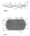
- Fig. 2 depicts an isometric view of a particulate filter in accordance with an embodiment of the invention
- Fig. 3 depicts a cross section side view of an arrangement of filter plates employed in the particulate filter of Figure 2 ;
- Fig. 4 depicts an enlarged front view of a portion of the filter plate depicted in Figures 2 and 3 ;
- Fig. 5 depicts an enlarged side view of a portion of the filter plate depicted in Figure 3 ;
- Fig. 6 depicts a cross section side view of another arrangement of filter plates in accordance with an embodiment of the invention.
- Fig. 7 depicts an enlarged illustrative view of filtration efficiency as a function of micropocket shape and flow rate
- Fig. 8 depicts an alternative front view of the filter plate arrangement depicted in Figure 4 .
- An embodiment of the invention provides a particulate filter for an exhaust system of an automotive diesel engine. While the embodiment described herein depicts an automotive diesel engine as an exemplary diesel powerplant using a particulate filter, it will be appreciated that the disclosed invention is also applicable to other diesel powerplants that require the functionality of a particulate filter herein disclosed, such as a diesel powered generator for example. While the disclosed invention is well suited for filtering the combustion byproducts of a diesel engine, it may also be applicable for filtering combustion byproducts of a gasoline powered engine.
- An exemplary exhaust system 100 for an automotive diesel engine is depicted in Figure 1 having manifold exhaust pipes 110 suitably connected at one end to exhaust manifolds (not shown) of the diesel engine (not shown) for receiving an exhaust flow, depicted generally as numeral 150, intermediate exhaust pipes 120, a turbocharger exhaust pipe 130 coupled to a tailpipe (not shown) for exhausting the conditioned exhaust flow to atmosphere, a turbocharger 140 suitably connected between intermediate exhaust pipes 120 and turbocharger exhaust pipe 130, and particulate filters 200 suitably connected intermediate manifold exhaust pipes 110 and intermediate exhaust pipes 120 for trapping exhaust particulates present in the exhaust flow 150.
- Exhaust flow 150 passes from exhaust manifolds (not shown) to manifold exhaust pipes 110, particulate filters 200, intermediate exhaust pipes 120, turbocharger 140, turbocharger exhaust pipe 130, and then to atmosphere.
- Exhaust system 100 has a nominal flow area equal to or greater than the inside cross-sectional flow area of manifold exhaust pipes 110.
- particulate filter 200 is arranged in a pre-turbo, as opposed to a post-turbo, location. Since the exhaust gas temperature is higher at a pre-turbo location (versus post-turbo), regeneration of particulate filter 200 may benefit by positioning particulate filter 200 at the pre-turbo location. However, as a filtering device, particulate filter 200 may be positioned at either a pre- or a post-turbo location.
- Each particulate filter 200 has a housing 210, which may be any form of construction and configuration suitable for the purpose, and a plurality of plates 220 arranged parallel to each other and retained within housing 210 by any means suitable for the purpose, the plurality of plates 220 composing a filter element for trapping exhaust particulates, as best seen by now referring to Figure 2 .
- Each plate 225 has a plurality of orifices 230 and a plurality of micropockets 240, best seen by referring to Figure 3 , which depicts plates 220 in cross-sectional side view through orifices 230 and micropockets 240.
- FIG. 4 An enlarged front view of a portion of plate 225 is depicted in Figure 4 showing orifices 230 and micropockets 240 as small and large discs, respectively, and arranged intermediate each other.
- Figure 8 depicts an alternative arrangement to the plate 225 of Figure 4 , where orifices 230 are depicted as small discs, funnel shaped surfaces 235 (discussed in reference to Figure 3 below) surrounding orifices 230 are depicted as larger concentric discs, and micropockets 240 are depicted as the regions between the funnel shaped surfaces 235.
- An embodiment of particulate filter 200 includes an arrangement of orifices 230 where the total flow through area of orifices 230 on each plate 220 is equal to or greater than the nominal flow area of exhaust system 100, thereby preventing excessive pressure drop within exhaust system 100.
- each plate 225 is formed by known forming means to create crescent shaped micropockets 240 with orifices 230 therebetween and a funnel shaped surface 235 around each orifice 230.
- Funnel shaped surface 235 may be fabricated, for example, by a die extrusion process.
- An embodiment of particulate filter 200 has the bottoms of each funnel shaped surface (funnel) 235 facing the exhaust flow 150.
- the term facing the exhaust flow as used herein refers to the orientation of a part that faces the direction from which the exhaust flow is locally traveling.
- micropockets 240 facing the exhaust flow 150 (as seen in Figure 3 ), that is, the internal crescent shaped surfaces of micropockets 240 face the exhaust flow 150.
- orifices 230 and micropockets 240 on successive plates 220 is such that the orifices 230 of a preceding plate, a first plate 226, are arranged in line with micropockets 240 of a succeeding plate, a second plate 227, as best seen by referring to Figures 3 and 5 , where Figure 5 depicts an enlarged side view of a portion of Figure 3 showing the exhaust flow 150 through orifices 230 of successive plates 220.
- the exhaust flow 150 through orifices 230 of first plate 226 is directed toward the centers of micropockets 240 of second plate 227, and the exhaust flow 150 through orifices 230 of second plate 227 is directed toward the centers of micropockets 240 of third plate 228.
- the crescent shaped micropockets 240 and the offset arrangement of orifices 230 and micropockets 240 from one plate 220 to the next results in exhaust particulates being trapped in micropockets 240 and the passing of a less contaminated flow to the next plate 220.
- the term in line with as used herein not only refers to an arrangement of orifices 230 of first plate 226 that aim the exhaust flow 150 directly at the center of micropockets 240 of second plate 227, but rather refers to the general flow from one plate 220 to the next where the exhaust flow 150 is directed toward the micropockets in the successive plate for the purpose of trapping exhaust particulates.
- an embodiment of particulate filter 200 has an arrangement of plates 220 where the gap G1 between the first two successive plates 220 is greater that the gap G2 between the last two successive plates 220 and where the gap g between each successive plate 220 decreases in dimension in the direction of exhaust flow 150.
- exhaust flow 150 travels through particulate filter 200, it is natural for larger particulates to be trapped in the micropockets 240 at the front of particulate filter 200 first, and for smaller particulates to travel further through particulate filter 200.
- gap g between each successive plate 220 By arranging gap g between each successive plate 220 to decrease in the direction of exhaust flow 150, the smaller particulates can be trapped at the end of particulate filter 200.
- FIG. 6 Another embodiment of particulate filter 200 is depicted in Figure 6 , which shows an arrangement of plates 220 that alternate in direction to produce an arrangement of plate pairs 245 having a first plate 246 and a second plate 247.
- micropockets 240 of first plate 246 face opposite to the direction of exhaust flow 150 and micropockets 240 of second plate 247 face the direction of exhaust flow 150, and orifices 230 of first plate 246 are arranged in line with micropockets 240 of second plate 247.
- This arrangement of plate pairs 245 continues for the balance of plates 220 in the particulate filter 200 of Figure 6 .
- gap h refers to the distance between the bottom of funnels 235 of first plate 246 and the bottom of micropockets 240 of second plate 247.
- gap H1 in the first plate pair 245 is greater than gap H2 in the last plate pair 245.
- the embodiment depicted in Figure 6 provides for a greater packing density of plates 220, thereby resulting in more exhaust filtration per increment of exhaust flow.
- the exhaust particulate filtering method begins with particulate filter 200 receiving exhaust flow 150 at one end 202 of particulate filter 200, where exhaust flow 150 then impinges on a plate 225 of a plurality of plates 220, each plate 220 having a plurality of orifices 230 and a plurality of micropockets 240.
- Plates 220 are arranged perpendicular to the exhaust flow 150, that is, facing the exhaust flow, and have gaps g separating them.
- separation gaps g decrease in magnitude in the direction of exhaust flow 150, thereby enabling small particulate filtration, and each micropocket 240 of each plate 220 faces the direction of exhaust flow 150.
- orifices 230 are arranged as funnels with funnel shaped surfaces 235, and the bottom of each funnel of each plate 220 is arranged to face the flow stream of exhaust flow 150.
- the exhaust particulate filtering method involves the impinging of exhaust flow 150 on plates 220 where micropockets 240 of each other plate are arranged to face the flow stream of exhaust flow 150.
- orifices 230 are arranged as funnels having a funnel shaped surface 235 where the bottoms of each funnel of each other plate 220 face the flow stream of exhaust flow 150.
- plates 220 are arranged perpendicular to the exhaust flow 150 with separation gaps h therebetween that decrease in magnitude in the direction of exhaust flow 150, thereby enabling small particulate filtration.
- the bottoms of the funnels of orifices 230 of each other plate 220 direct exhaust flow 150 toward micropockets 240 of each subsequent plate 220.
- plates 220 are fabricated from a known metallic substrate composition having iron, chromium, aluminum, and yttrium, which is then coated with a catalyst such as platinum.
- the catalyzed particulate trap can facilitate low temperature oxidation of carbonaceous components in the deposited particulates.
- the metallic components in the particulate deposits (known as ash) cannot be burned.
- Orifices 230 and gaps g and h are sized to allow the passage of ash particles, which are small in size compared to the deposited particulates. In an embodiment, orifices 230 are about .05 centimeters in diameter, and gaps g and h are about. 01 centimeters to about .1 centimeters in dimension.
- Figure 7 depicts several shapes that may be employed for micropockets 240, including round 250, rectangle 260, and crescent 270.
- the estimated filtration efficiency is represented by shaded regions 255, 265, 275 for each shape 250, 260, 270, respectively.
Description
- The present disclosure relates generally to an exhaust system, and particularly to a particulate filter for an exhaust system.
- Automotive exhaust systems for diesel and other internal combustion engines typically include an exhaust subsystem that limits the mass of particulate matter emitted with the exhaust gases. In diesel engine systems, this matter typically includes both carbonaceous components and metallic components. Present filtering methods to trap the exhaust particulates include both surface filtration and depth filtration approaches. Surface filtration relies on interception as the mechanism for particulate filtration, while depth filtration relies on impaction as the main mechanism for particulate filtration. With surface filtration systems, particulate deposits tend to block the flow path and lead to high trapping efficiency and an increase in pressure drop over time. With depth filtration systems, particulate deposits do not block the flow path, which leads to low trapping efficiency and limited change in pressure drop over time. In view of present particulate filter arrangements, it is desirable to have a more advanced particulate filter that can operate in limited space, have sufficient trapping efficiency, and can operate with limited change in its pressure drop characteristics over time.
-
EP 0 353 679 A1 describes a filter apparatus which is designed for filtering solid, liquid or gaseous, electrically uncharged or electrically charged particles out of a gaseous flow medium as it flows through the filter apparatus. The filter apparatus has a housing and filter elements arranged in the housing. In addition, the filter elements are arranged parallel to each other and spaced from each other in the direction of flow of the gaseous medium to the apparatus. Each filter element has a plate-like carrier element and a substrate which are provided with spaced-apart openings. The substrate serves for the storage of a filter medium. Each opening in the filter element has a sleeve-like guide element for the flow medium, wherein the guide element extends around the edge of the corresponding opening. The guide elements which project at least at the upstream side prevent filter medium at the individual substrates from being unintentionally entrained through the openings, even at high flow rates in respect of the flow medium. - In one embodiment, a particulate filter for an exhaust system having an exhaust flow and a nominal flow area includes a housing and a plurality of plates arranged parallel to each other within the housing, each plate having a plurality of orifices and a plurality of micropockets configured to trap exhaust particulates.
- In another embodiment, a particulate filter for an exhaust system having an exhaust flow and a nominal flow area includes a housing and a plurality of plates, each plate having a plurality of orifices and a plurality of micropockets arranged within the housing and configured to trap exhaust particulates. The plates are arranged parallel to each other as plate pairs and have their micropockets facing the exhaust flow. The plates have gaps between them that decrease in size in the direction of the exhaust flow. The orifices of each plate are in line with the micropockets of an adjacent plate, each orifice being surrounded by a funnel shaped surface with the bottom of the funnel facing the exhaust flow. The total flow through area of the orifices of each plate is equal to or greater than the nominal flow area of the exhaust system.
- In a further embodiment, a method for filtering particulates of an exhaust flow of an exhaust system includes receiving the exhaust flow at one end of a particulate filter, impinging the exhaust flow on the plates, collecting a portion of the particulates at micropockets on the plates, passing a portion of the exhaust flow through orifices on the plates toward a subsequent plate, repeating the impinging, collecting, and passing processes for all plates, and discharging the exhaust flow at an opposite end of the particulate filter. The plates are arranged perpendicular to the exhaust flow and have gaps between them. The orifices of each plate are in line with the micropockets of a subsequent plate.
- Referring to the exemplary drawings wherein like elements are numbered alike in the accompanying Figures:
-
Fig. 1 depicts an exhaust system employing an embodiment of the invention; -
Fig. 2 depicts an isometric view of a particulate filter in accordance with an embodiment of the invention; -
Fig. 3 depicts a cross section side view of an arrangement of filter plates employed in the particulate filter ofFigure 2 ; -
Fig. 4 depicts an enlarged front view of a portion of the filter plate depicted inFigures 2 and3 ; -
Fig. 5 depicts an enlarged side view of a portion of the filter plate depicted inFigure 3 ; -
Fig. 6 depicts a cross section side view of another arrangement of filter plates in accordance with an embodiment of the invention; -
Fig. 7 depicts an enlarged illustrative view of filtration efficiency as a function of micropocket shape and flow rate; and -
Fig. 8 depicts an alternative front view of the filter plate arrangement depicted inFigure 4 . - An embodiment of the invention provides a particulate filter for an exhaust system of an automotive diesel engine. While the embodiment described herein depicts an automotive diesel engine as an exemplary diesel powerplant using a particulate filter, it will be appreciated that the disclosed invention is also applicable to other diesel powerplants that require the functionality of a particulate filter herein disclosed, such as a diesel powered generator for example. While the disclosed invention is well suited for filtering the combustion byproducts of a diesel engine, it may also be applicable for filtering combustion byproducts of a gasoline powered engine.
- An
exemplary exhaust system 100 for an automotive diesel engine (not shown) is depicted inFigure 1 havingmanifold exhaust pipes 110 suitably connected at one end to exhaust manifolds (not shown) of the diesel engine (not shown) for receiving an exhaust flow, depicted generally asnumeral 150,intermediate exhaust pipes 120, aturbocharger exhaust pipe 130 coupled to a tailpipe (not shown) for exhausting the conditioned exhaust flow to atmosphere, aturbocharger 140 suitably connected betweenintermediate exhaust pipes 120 andturbocharger exhaust pipe 130, andparticulate filters 200 suitably connected intermediatemanifold exhaust pipes 110 andintermediate exhaust pipes 120 for trapping exhaust particulates present in theexhaust flow 150.Exhaust flow 150 passes from exhaust manifolds (not shown) to manifoldexhaust pipes 110,particulate filters 200,intermediate exhaust pipes 120,turbocharger 140,turbocharger exhaust pipe 130, and then to atmosphere.Exhaust system 100 has a nominal flow area equal to or greater than the inside cross-sectional flow area ofmanifold exhaust pipes 110. - In the embodiment depicted in
Figure 1 ,particulate filter 200 is arranged in a pre-turbo, as opposed to a post-turbo, location. Since the exhaust gas temperature is higher at a pre-turbo location (versus post-turbo), regeneration ofparticulate filter 200 may benefit by positioningparticulate filter 200 at the pre-turbo location. However, as a filtering device,particulate filter 200 may be positioned at either a pre- or a post-turbo location. - Each
particulate filter 200 has ahousing 210, which may be any form of construction and configuration suitable for the purpose, and a plurality ofplates 220 arranged parallel to each other and retained withinhousing 210 by any means suitable for the purpose, the plurality ofplates 220 composing a filter element for trapping exhaust particulates, as best seen by now referring toFigure 2 . Eachplate 225 has a plurality oforifices 230 and a plurality ofmicropockets 240, best seen by referring toFigure 3 , which depictsplates 220 in cross-sectional side view throughorifices 230 andmicropockets 240. An enlarged front view of a portion ofplate 225 is depicted inFigure 4 showingorifices 230 andmicropockets 240 as small and large discs, respectively, and arranged intermediate each other.Figure 8 depicts an alternative arrangement to theplate 225 ofFigure 4 , whereorifices 230 are depicted as small discs, funnel shaped surfaces 235 (discussed in reference toFigure 3 below) surroundingorifices 230 are depicted as larger concentric discs, andmicropockets 240 are depicted as the regions between the funnelshaped surfaces 235. An embodiment ofparticulate filter 200 includes an arrangement oforifices 230 where the total flow through area oforifices 230 on eachplate 220 is equal to or greater than the nominal flow area ofexhaust system 100, thereby preventing excessive pressure drop withinexhaust system 100. - Referring back now to
Figure 3 , eachplate 225 is formed by known forming means to create crescentshaped micropockets 240 withorifices 230 therebetween and a funnel shapedsurface 235 around eachorifice 230. Funnelshaped surface 235 may be fabricated, for example, by a die extrusion process. An embodiment ofparticulate filter 200 has the bottoms of each funnel shaped surface (funnel) 235 facing theexhaust flow 150. The term facing the exhaust flow as used herein refers to the orientation of a part that faces the direction from which the exhaust flow is locally traveling. The arrangement ofplates 220 with the bottoms offunnel 235 facing theexhaust flow 150 also results inmicropockets 240 facing the exhaust flow 150 (as seen inFigure 3 ), that is, the internal crescent shaped surfaces ofmicropockets 240 face theexhaust flow 150. - The arrangement of
orifices 230 andmicropockets 240 onsuccessive plates 220 is such that theorifices 230 of a preceding plate, afirst plate 226, are arranged in line withmicropockets 240 of a succeeding plate, asecond plate 227, as best seen by referring toFigures 3 and5 , whereFigure 5 depicts an enlarged side view of a portion ofFigure 3 showing theexhaust flow 150 throughorifices 230 ofsuccessive plates 220. As depicted inFigure 5 , theexhaust flow 150 throughorifices 230 offirst plate 226 is directed toward the centers ofmicropockets 240 ofsecond plate 227, and theexhaust flow 150 throughorifices 230 ofsecond plate 227 is directed toward the centers ofmicropockets 240 ofthird plate 228. As theexhaust flow 150 travels throughparticulate filter 200, the crescent shapedmicropockets 240 and the offset arrangement oforifices 230 andmicropockets 240 from oneplate 220 to the next, results in exhaust particulates being trapped inmicropockets 240 and the passing of a less contaminated flow to thenext plate 220. It will be appreciated that the term in line with as used herein not only refers to an arrangement oforifices 230 offirst plate 226 that aim theexhaust flow 150 directly at the center ofmicropockets 240 ofsecond plate 227, but rather refers to the general flow from oneplate 220 to the next where theexhaust flow 150 is directed toward the micropockets in the successive plate for the purpose of trapping exhaust particulates. - Referring now back to
Figures 2 and3 , an embodiment ofparticulate filter 200 has an arrangement ofplates 220 where the gap G1 between the first twosuccessive plates 220 is greater that the gap G2 between the last twosuccessive plates 220 and where the gap g between eachsuccessive plate 220 decreases in dimension in the direction ofexhaust flow 150. Asexhaust flow 150 travels throughparticulate filter 200, it is natural for larger particulates to be trapped in themicropockets 240 at the front ofparticulate filter 200 first, and for smaller particulates to travel further throughparticulate filter 200. By arranging gap g between eachsuccessive plate 220 to decrease in the direction ofexhaust flow 150, the smaller particulates can be trapped at the end ofparticulate filter 200. - Another embodiment of
particulate filter 200 is depicted inFigure 6 , which shows an arrangement ofplates 220 that alternate in direction to produce an arrangement ofplate pairs 245 having afirst plate 246 and asecond plate 247. As depicted inFigure 6 ,micropockets 240 offirst plate 246 face opposite to the direction ofexhaust flow 150 andmicropockets 240 ofsecond plate 247 face the direction ofexhaust flow 150, andorifices 230 offirst plate 246 are arranged in line withmicropockets 240 ofsecond plate 247. This arrangement of plate pairs 245 continues for the balance ofplates 220 in theparticulate filter 200 ofFigure 6 . Similar to gap g discussed above, the embodiment depicted inFigure 6 has a gap h that decreases in the direction of exhaust flow, thereby enabling more effective filtering of smaller particulates. InFigure 6 , gap h refers to the distance between the bottom offunnels 235 offirst plate 246 and the bottom ofmicropockets 240 ofsecond plate 247. As shown, gap H1 in thefirst plate pair 245 is greater than gap H2 in thelast plate pair 245. The embodiment depicted inFigure 6 provides for a greater packing density ofplates 220, thereby resulting in more exhaust filtration per increment of exhaust flow. - In an embodiment of
particulate filter 200, the exhaust particulate filtering method begins withparticulate filter 200 receivingexhaust flow 150 at oneend 202 ofparticulate filter 200, whereexhaust flow 150 then impinges on aplate 225 of a plurality ofplates 220, eachplate 220 having a plurality oforifices 230 and a plurality ofmicropockets 240.Plates 220 are arranged perpendicular to theexhaust flow 150, that is, facing the exhaust flow, and have gaps g separating them. In an embodiment, separation gaps g decrease in magnitude in the direction ofexhaust flow 150, thereby enabling small particulate filtration, and eachmicropocket 240 of eachplate 220 faces the direction ofexhaust flow 150. In another embodiment,orifices 230 are arranged as funnels with funnel shapedsurfaces 235, and the bottom of each funnel of eachplate 220 is arranged to face the flow stream ofexhaust flow 150. - Following the impinging of
exhaust flow 150 onplate 225, a portion of the exhaust particulates become trapped, or are collected, atmicropockets 240, and a portion ofexhaust flow 150 passes throughorifices 230 toward asubsequent plate 220. As discussed above, to facilitate filtration,orifices 230 of eachplate 220 are in line with associatedmicropockets 240 of eachsubsequent plate 220. - The processes involved in impinging the
exhaust flow 150 on aplate 220, collecting a portion of the exhaust particulates atmicropockets 240, and passing a portion of the exhaust flow to asubsequent plate 220 throughorifices 230, continues for the plurality ofplates 220 withinparticulate filter 200. At theopposite end 204 ofparticulate filter 200, filteredexhaust flow 150 is discharged and received byintermediate exhaust pipes 120. - In another embodiment of
particulate filter 200, the exhaust particulate filtering method involves the impinging ofexhaust flow 150 onplates 220 wheremicropockets 240 of each other plate are arranged to face the flow stream ofexhaust flow 150. In this embodiment,orifices 230 are arranged as funnels having a funnel shapedsurface 235 where the bottoms of each funnel of eachother plate 220 face the flow stream ofexhaust flow 150. As discussed above,plates 220 are arranged perpendicular to theexhaust flow 150 with separation gaps h therebetween that decrease in magnitude in the direction ofexhaust flow 150, thereby enabling small particulate filtration. The bottoms of the funnels oforifices 230 of eachother plate 220direct exhaust flow 150 towardmicropockets 240 of eachsubsequent plate 220. - In an embodiment,
plates 220 are fabricated from a known metallic substrate composition having iron, chromium, aluminum, and yttrium, which is then coated with a catalyst such as platinum. The catalyzed particulate trap can facilitate low temperature oxidation of carbonaceous components in the deposited particulates. The metallic components in the particulate deposits (known as ash) cannot be burned.Orifices 230 and gaps g and h are sized to allow the passage of ash particles, which are small in size compared to the deposited particulates. In an embodiment,orifices 230 are about .05 centimeters in diameter, and gaps g and h are about. 01 centimeters to about .1 centimeters in dimension.Figure 7 depicts several shapes that may be employed formicropockets 240, includinground 250,rectangle 260, andcrescent 270. The estimated filtration efficiency is represented byshaded regions shape combustion particles 280 will be trapped, or are collected, more efficiently using acrescent shape 270 formicropocket 240. - While the invention has been described with reference to exemplary embodiments, it will be understood by those skilled in the art that various changes may be made and equivalents may be substituted for elements thereof without departing from the scope of the invention. In addition, many modifications may be made to adapt a particular situation or material to the teachings of the invention without departing from the essential scope thereof. Therefore, it is intended that the invention not be limited to the particular embodiment disclosed as the best mode contemplated for carrying out this invention, but that the invention will include all embodiments falling within the scope of the appended claims. Moreover, the use of the terms first, second, etc. do not denote any order or importance, but rather the terms first, second, etc. are used to distinguish one element from another. Furthermore, the use of the terms a, an, etc. do not denote a limitation of quantity, but rather denote the presence of at least one of the referenced item.
Claims (12)
- A particulate filter (200) for an exhaust system (100) having an exhaust flow (150) and a nominal flow area, comprising:a housing (210); anda plurality of plates (220) arranged perpendicular to the exhaust flow and parallel to each other within said housing (210), each of said plurality of plates (220) having a plurality of orifices (230) and a plurality of micropockets (240) configured to trap exhaust particulates,said plurality of plates (220) defining a plurality of gaps (g, h) therebetween, said plurality of gaps (g, h) being configured having a decreasing dimension in the direction of the exhaust flow (150).
- The particulate filter of Claim 1, wherein said plurality of orifices (230) and said plurality of micropockets (240) of each of said plurality of plates (220) are arranged intermediate each other.
- The particulate filter of Claim 2, wherein said plurality of orifices (230) are surrounded by a funnel shaped surface (235), the bottoms of each funnel (235) of at least one plate of said plurality of plates (220) facing the exhaust flow (150).
- The particulate filter of Claim 1, wherein said plurality of plates (220) comprises first and second plates (226, 227) each having said plurality of micropockets (240) facing the exhaust flow (150), said plurality of orifices (230) of said first plate (226) being in line with said plurality of micropockets (240) of said second plate (227).
- The particulate filter of Claim 1, wherein the total flow through area of said plurality of orifices (230) of each of said plurality of plates (220) is equal to or greater than the nominal flow area of the exhaust system (100).
- The particulate filter of Claim 1, wherein said plurality of plates (220) comprises a plurality of plate pairs (245) including a first plate (246) having said plurality of micropockets (240) facing opposite to the exhaust flow (150) and an adjacent second plate (247) having said plurality of micropockets (240) facing the exhaust flow (150), said plurality of orifices (230) of said first plate (246) being in line with said plurality of micropockets (240) of said second plate (247).
- A method for filtering particulates of an exhaust flow (150) of an exhaust system (100), comprising:receiving the exhaust flow (150) at one end of a particulate filter (200);impinging the exhaust flow (150) on a plate of a plurality of plates (220) each having a plurality of orifices (230) and a plurality of micropockets (240), the plurality of plates (220) arranged perpendicular to the exhaust flow (150) with gaps (g, h) therebetween decreasing in magnitude in the direction of exhaust flow (150);collecting a portion of the particulates at the plurality of micropockets (240) of the plate;passing a portion of the exhaust flow (150) through the plurality of orifices (230) of the plate toward a subsequent plate;repeating said impinging the exhaust flow (150), said collecting a portion of the particulates, and said passing a portion of the exhaust flow (150), for the plurality of plates (220); anddischarging the exhaust flow (150) at an opposite end of the particulate filter (200).
- The method of Claim 7, wherein said impinging the exhaust flow further comprises impinging the exhaust flow on a plate of a plurality of plates, the plurality of micropockets of each plate being configured to face the flow stream of the exhaust flow.
- The method of Claim 7, wherein said impinging the exhaust flow (150) further comprises impinging the exhaust flow (150) on a plate of a plurality of plates (220) with the plurality of orifices (230) arranged as funnels (235), the bottom of each funnel (235) of each of the plurality of plates (220) facing the flow stream of the exhaust flow (150).
- The method of Claim 7, wherein said impinging the exhaust flow (150) further comprises impinging the exhaust flow (150) on a plate of a plurality of plates (220), the plurality of micropockets (240) of each other plate being configured to face the flow stream of the exhaust flow (150).
- The method of Claim 10, wherein said impinging the exhaust flow (150) further comprises impinging the exhaust flow (150) on a plate of a plurality of plates (220) with the plurality of orifices (230) arranged as funnels (235), the bottom of each funnel (235) of each other plate facing the flow stream of the exhaust flow (150).
- The method of Claim 7, wherein the plurality of orifices (230) of the plate are in line with the micropockets (240) of the subsequent plate.
Applications Claiming Priority (3)
| Application Number | Priority Date | Filing Date | Title |
|---|---|---|---|
| US10/378,270 US6764532B1 (en) | 2003-03-03 | 2003-03-03 | Method and apparatus for filtering exhaust particulates |
| US378270 | 2003-03-03 | ||
| PCT/US2004/005987 WO2004078319A1 (en) | 2003-03-03 | 2004-02-27 | Method and apparatus for filtering exhaust particulates |
Publications (3)
| Publication Number | Publication Date |
|---|---|
| EP1601439A1 EP1601439A1 (en) | 2005-12-07 |
| EP1601439A4 EP1601439A4 (en) | 2007-05-09 |
| EP1601439B1 true EP1601439B1 (en) | 2010-04-07 |
Family
ID=32681784
Family Applications (1)
| Application Number | Title | Priority Date | Filing Date |
|---|---|---|---|
| EP04715700A Expired - Fee Related EP1601439B1 (en) | 2003-03-03 | 2004-02-27 | Method and apparatus for filtering exhaust particulates |
Country Status (5)
| Country | Link |
|---|---|
| US (1) | US6764532B1 (en) |
| EP (1) | EP1601439B1 (en) |
| CN (1) | CN100361728C (en) |
| DE (1) | DE602004026421D1 (en) |
| WO (1) | WO2004078319A1 (en) |
Families Citing this family (10)
| Publication number | Priority date | Publication date | Assignee | Title |
|---|---|---|---|---|
| DE102006003317B4 (en) | 2006-01-23 | 2008-10-02 | Alstom Technology Ltd. | Tube bundle heat exchanger |
| US9557119B2 (en) | 2009-05-08 | 2017-01-31 | Arvos Inc. | Heat transfer sheet for rotary regenerative heat exchanger |
| US8622115B2 (en) * | 2009-08-19 | 2014-01-07 | Alstom Technology Ltd | Heat transfer element for a rotary regenerative heat exchanger |
| US9200853B2 (en) | 2012-08-23 | 2015-12-01 | Arvos Technology Limited | Heat transfer assembly for rotary regenerative preheater |
| US10175006B2 (en) | 2013-11-25 | 2019-01-08 | Arvos Ljungstrom Llc | Heat transfer elements for a closed channel rotary regenerative air preheater |
| CN104949213B (en) | 2014-03-28 | 2017-09-29 | Lg电子株式会社 | Air purifier |
| CN104949212B (en) * | 2014-03-28 | 2017-11-14 | Lg电子株式会社 | Air purifier |
| US10927457B2 (en) * | 2015-03-04 | 2021-02-23 | Toshiba Memory Corporation | Semiconductor manufacturing apparatus |
| US10094626B2 (en) | 2015-10-07 | 2018-10-09 | Arvos Ljungstrom Llc | Alternating notch configuration for spacing heat transfer sheets |
| DE102017124225A1 (en) * | 2017-10-18 | 2019-04-18 | Man Diesel & Turbo Se | Exhaust after-treatment system and exhaust aftertreatment process |
Family Cites Families (25)
| Publication number | Priority date | Publication date | Assignee | Title |
|---|---|---|---|---|
| DE244548C (en) * | ||||
| US1783143A (en) * | 1926-01-09 | 1930-11-25 | Schrempp Albert | Filter device |
| US2847086A (en) * | 1953-08-04 | 1958-08-12 | Muller Paul Adolf | Filtering material |
| US2723725A (en) * | 1954-05-18 | 1955-11-15 | Charles J Keiffer | Dust separating and recovering apparatus |
| US3807144A (en) * | 1972-01-31 | 1974-04-30 | P Graybill | Air rectifiers, apparatus with process |
| FR2325413A1 (en) * | 1975-09-26 | 1977-04-22 | Zundel Marcel | Removing liq. droplets and solid particles from gases - using a separator which incorporates a series of vertical grids |
| CA1145270A (en) | 1979-12-03 | 1983-04-26 | Morris Berg | Ceramic filters for diesel exhaust particulates and methods of making |
| JPS57113822A (en) * | 1980-12-30 | 1982-07-15 | Nippon Soken Inc | Fine particle collecting filter |
| US4390355A (en) | 1982-02-02 | 1983-06-28 | General Motors Corporation | Wall-flow monolith filter |
| US4423090A (en) | 1982-02-02 | 1983-12-27 | General Motors Corporation | Method of making wall-flow monolith filter |
| DE8629355U1 (en) * | 1986-10-31 | 1987-03-05 | Simmerlein-Erlbacher, Ewald Wilhelm, 8570 Pegnitz, De | |
| US4925561A (en) * | 1988-03-31 | 1990-05-15 | Tsuchiya Mfg. Co., Ltd. | Composite planar and triangularly pleated filter element |
| BR8907047A (en) * | 1988-08-04 | 1991-01-02 | Simmerlein Erlbacher E W | FILTERING DEVICE |
| US5051241A (en) | 1988-11-18 | 1991-09-24 | Pfefferle William C | Microlith catalytic reaction system |
| US5002597A (en) * | 1989-04-03 | 1991-03-26 | Invent Ag | Aerodynamic filter |
| US5294411A (en) | 1989-04-17 | 1994-03-15 | Emitec Gesellschaft Fuer Emissionstechnologie Mbh | Honeycomb body with heatable catalytic active coating |
| DE9102970U1 (en) * | 1991-03-13 | 1991-10-10 | Kalthoff Luftfilter Und Filtermedien Gmbh, 4714 Selm, De | |
| US5204027A (en) * | 1992-02-04 | 1993-04-20 | Armstrong Charles M | Fluid contact panels |
| US5253476A (en) | 1992-02-21 | 1993-10-19 | Northeastern University | Pulsed, reverse-flow, regenerated diesel trap capturing soot, ash and PAH's |
| US5426936A (en) | 1992-02-21 | 1995-06-27 | Northeastern University | Diesel engine exhaust gas recirculation system for NOx control incorporating a compressed air regenerative particulate control system |
| AU5869494A (en) * | 1992-12-01 | 1994-06-22 | Koch Engineering Company, Inc. | Nested packing for an exchange column |
| US6010554A (en) * | 1997-06-23 | 2000-01-04 | Battelle Memorial Institute | Micro-machined virtual impactor and method of operation |
| AU754545B2 (en) * | 1999-09-15 | 2002-11-21 | Brentwood Industries, Inc. | Contact bodies and method and apparatus of making same |
| CN2464426Y (en) * | 2001-01-23 | 2001-12-12 | 张学龙 | Cooking fume purifier |
| US6576045B2 (en) * | 2001-09-10 | 2003-06-10 | Fleetguard, Inc. | Multi-stage diesel particulate collector system with combined processes of inertial impaction, virtual impaction, and filtration |
-
2003
- 2003-03-03 US US10/378,270 patent/US6764532B1/en not_active Expired - Lifetime
-
2004
- 2004-02-27 WO PCT/US2004/005987 patent/WO2004078319A1/en active Application Filing
- 2004-02-27 CN CNB2004800117715A patent/CN100361728C/en not_active Expired - Fee Related
- 2004-02-27 EP EP04715700A patent/EP1601439B1/en not_active Expired - Fee Related
- 2004-02-27 DE DE602004026421T patent/DE602004026421D1/en not_active Expired - Lifetime
Also Published As
| Publication number | Publication date |
|---|---|
| WO2004078319A1 (en) | 2004-09-16 |
| EP1601439A1 (en) | 2005-12-07 |
| CN1780676A (en) | 2006-05-31 |
| DE602004026421D1 (en) | 2010-05-20 |
| EP1601439A4 (en) | 2007-05-09 |
| US6764532B1 (en) | 2004-07-20 |
| CN100361728C (en) | 2008-01-16 |
Similar Documents
| Publication | Publication Date | Title |
|---|---|---|
| US6712884B2 (en) | Particle trap and process for separating particles out of an exhaust gas flow and honeycomb body and exhaust system having a particle trap | |
| US6576045B2 (en) | Multi-stage diesel particulate collector system with combined processes of inertial impaction, virtual impaction, and filtration | |
| JP4639024B2 (en) | Dust collection elements associated with methods of removing soot particles from exhaust gases | |
| US6835224B2 (en) | Open end diesel particulate trap | |
| RU2431750C2 (en) | Separator of solid particles and procedure for separation of solid particles from flow of exhaust gases of internal combustion engine | |
| EP1601439B1 (en) | Method and apparatus for filtering exhaust particulates | |
| EP1601440B1 (en) | Method for filtering exhaust particulates | |
| RU2009123453A (en) | PARTICLE SEPARATOR, AND ALSO A METHOD FOR SEPARATING PARTICLES FROM THE EXHAUST GAS FLOW OF THE INTERNAL COMBUSTION ENGINE | |
| EP2761146B1 (en) | Apparatus and method for filtering engine exhaust gases | |
| CN114080494A (en) | Exhaust gas purifying catalyst device | |
| KR101174113B1 (en) | Metal foam filter for diesel particulate filter trap | |
| JPH04255513A (en) | Exhaust filter for internal combustion engine | |
| KR100745109B1 (en) | Filter for an apparatus for purifying exhaust gas from a diesel engine | |
| KR20060136014A (en) | Filter for an apparatus for purifying exhaust gas from a diesel engine | |
| CN101072929B (en) | Filter structure and exhaust line associated therewith | |
| JP2004108202A (en) | Particulate filter | |
| US10494970B2 (en) | Emissions control substrate | |
| JP7187250B2 (en) | Exhaust gas aftertreatment system and method for exhaust gas aftertreatment | |
| US7753978B2 (en) | Filter system | |
| KR20090095182A (en) | Particulate Filter | |
| JP2007046516A (en) | Exhaust gas treatment device | |
| KR20220081812A (en) | Exhaust gas filtering device with heat flow distribution function | |
| JPH0466712A (en) | Exhaust purifier for engine | |
| KR20070000043A (en) | Filter for eliminating particulate matters in a diesel engine | |
| JP2722854B2 (en) | Exhaust filter for internal combustion engine |
Legal Events
| Date | Code | Title | Description |
|---|---|---|---|
| PUAI | Public reference made under article 153(3) epc to a published international application that has entered the european phase |
Free format text: ORIGINAL CODE: 0009012 |
|
| 17P | Request for examination filed |
Effective date: 20050905 |
|
| AK | Designated contracting states |
Kind code of ref document: A1 Designated state(s): AT BE BG CH CY CZ DE DK EE ES FI FR GB GR HU IE IT LI LU MC NL PT RO SE SI SK TR |
|
| AX | Request for extension of the european patent |
Extension state: AL LT LV MK |
|
| DAX | Request for extension of the european patent (deleted) | ||
| RBV | Designated contracting states (corrected) |
Designated state(s): DE FR GB |
|
| A4 | Supplementary search report drawn up and despatched |
Effective date: 20070405 |
|
| RIC1 | Information provided on ipc code assigned before grant |
Ipc: B01D 46/12 20060101AFI20070330BHEP Ipc: F01N 3/022 20060101ALI20070330BHEP Ipc: F01N 3/023 20060101ALI20070330BHEP |
|
| 17Q | First examination report despatched |
Effective date: 20071002 |
|
| GRAP | Despatch of communication of intention to grant a patent |
Free format text: ORIGINAL CODE: EPIDOSNIGR1 |
|
| GRAS | Grant fee paid |
Free format text: ORIGINAL CODE: EPIDOSNIGR3 |
|
| GRAA | (expected) grant |
Free format text: ORIGINAL CODE: 0009210 |
|
| AK | Designated contracting states |
Kind code of ref document: B1 Designated state(s): DE FR GB |
|
| REG | Reference to a national code |
Ref country code: GB Ref legal event code: FG4D |
|
| REF | Corresponds to: |
Ref document number: 602004026421 Country of ref document: DE Date of ref document: 20100520 Kind code of ref document: P |
|
| PLBE | No opposition filed within time limit |
Free format text: ORIGINAL CODE: 0009261 |
|
| STAA | Information on the status of an ep patent application or granted ep patent |
Free format text: STATUS: NO OPPOSITION FILED WITHIN TIME LIMIT |
|
| 26N | No opposition filed |
Effective date: 20110110 |
|
| REG | Reference to a national code |
Ref country code: DE Ref legal event code: R081 Ref document number: 602004026421 Country of ref document: DE Owner name: GM GLOBAL TECHNOLOGY OPERATIONS LLC (N. D. GES, US Free format text: FORMER OWNER: GENERAL MOTORS CORP. (N.D.GES.D. STAATES DELAWARE), DETROIT, US Effective date: 20110330 Ref country code: DE Ref legal event code: R081 Ref document number: 602004026421 Country of ref document: DE Owner name: GM GLOBAL TECHNOLOGY OPERATIONS LLC (N. D. GES, US Free format text: FORMER OWNER: GENERAL MOTORS CORP. (N.D.GES.D. STAATES DELAWARE), DETROIT, MICH., US Effective date: 20110330 |
|
| REG | Reference to a national code |
Ref country code: DE Ref legal event code: R082 Ref document number: 602004026421 Country of ref document: DE Representative=s name: MANITZ, FINSTERWALD & PARTNER GBR, DE |
|
| GBPC | Gb: european patent ceased through non-payment of renewal fee |
Effective date: 20110227 |
|
| REG | Reference to a national code |
Ref country code: FR Ref legal event code: ST Effective date: 20111102 |
|
| PG25 | Lapsed in a contracting state [announced via postgrant information from national office to epo] |
Ref country code: FR Free format text: LAPSE BECAUSE OF NON-PAYMENT OF DUE FEES Effective date: 20110228 |
|
| PG25 | Lapsed in a contracting state [announced via postgrant information from national office to epo] |
Ref country code: GB Free format text: LAPSE BECAUSE OF NON-PAYMENT OF DUE FEES Effective date: 20110227 |
|
| PGFP | Annual fee paid to national office [announced via postgrant information from national office to epo] |
Ref country code: DE Payment date: 20120222 Year of fee payment: 9 |
|
| REG | Reference to a national code |
Ref country code: DE Ref legal event code: R082 Ref document number: 602004026421 Country of ref document: DE Representative=s name: MANITZ, FINSTERWALD & PARTNER GBR, DE |
|
| REG | Reference to a national code |
Ref country code: DE Ref legal event code: R081 Ref document number: 602004026421 Country of ref document: DE Owner name: GM GLOBAL TECHNOLOGY OPERATIONS LLC (N. D. GES, US Free format text: FORMER OWNER: GM GLOBAL TECHNOLOGY OPERATIONS, INC., DETROIT, US Effective date: 20121019 Ref country code: DE Ref legal event code: R082 Ref document number: 602004026421 Country of ref document: DE Representative=s name: MANITZ, FINSTERWALD & PARTNER GBR, DE Effective date: 20121019 Ref country code: DE Ref legal event code: R082 Ref document number: 602004026421 Country of ref document: DE Representative=s name: MANITZ, FINSTERWALD & PARTNER GBR, DE Effective date: 20110812 Ref country code: DE Ref legal event code: R081 Ref document number: 602004026421 Country of ref document: DE Owner name: GM GLOBAL TECHNOLOGY OPERATIONS LLC (N. D. GES, US Free format text: FORMER OWNER: GM GLOBAL TECHNOLOGY OPERATIONS, INC., DETROIT, MICH., US Effective date: 20121019 |
|
| REG | Reference to a national code |
Ref country code: DE Ref legal event code: R119 Ref document number: 602004026421 Country of ref document: DE Effective date: 20130903 |
|
| PG25 | Lapsed in a contracting state [announced via postgrant information from national office to epo] |
Ref country code: DE Free format text: LAPSE BECAUSE OF NON-PAYMENT OF DUE FEES Effective date: 20130903 |