EP1601385B1 - Device for sterilising instruments - Google Patents
Device for sterilising instruments Download PDFInfo
- Publication number
- EP1601385B1 EP1601385B1 EP04719344A EP04719344A EP1601385B1 EP 1601385 B1 EP1601385 B1 EP 1601385B1 EP 04719344 A EP04719344 A EP 04719344A EP 04719344 A EP04719344 A EP 04719344A EP 1601385 B1 EP1601385 B1 EP 1601385B1
- Authority
- EP
- European Patent Office
- Prior art keywords
- radiation source
- equipment
- light
- instruments
- elongated
- Prior art date
- Legal status (The legal status is an assumption and is not a legal conclusion. Google has not performed a legal analysis and makes no representation as to the accuracy of the status listed.)
- Expired - Lifetime
Links
- 230000001954 sterilising effect Effects 0.000 title claims abstract description 20
- 230000005855 radiation Effects 0.000 claims abstract description 33
- 238000012544 monitoring process Methods 0.000 claims abstract description 9
- 238000004659 sterilization and disinfection Methods 0.000 claims description 15
- 230000004888 barrier function Effects 0.000 claims description 13
- 238000005192 partition Methods 0.000 claims description 10
- 238000003780 insertion Methods 0.000 claims description 7
- 230000037431 insertion Effects 0.000 claims description 7
- 238000005259 measurement Methods 0.000 claims 2
- 238000010586 diagram Methods 0.000 description 10
- 230000011664 signaling Effects 0.000 description 7
- 230000002035 prolonged effect Effects 0.000 description 6
- 238000000034 method Methods 0.000 description 5
- 230000008569 process Effects 0.000 description 5
- 244000052616 bacterial pathogen Species 0.000 description 2
- 230000002950 deficient Effects 0.000 description 2
- 239000012777 electrically insulating material Substances 0.000 description 2
- 239000000725 suspension Substances 0.000 description 2
- 241000894006 Bacteria Species 0.000 description 1
- 241000588724 Escherichia coli Species 0.000 description 1
- 230000004913 activation Effects 0.000 description 1
- 230000032683 aging Effects 0.000 description 1
- 230000001580 bacterial effect Effects 0.000 description 1
- 230000008901 benefit Effects 0.000 description 1
- 230000003247 decreasing effect Effects 0.000 description 1
- 230000000249 desinfective effect Effects 0.000 description 1
- 238000001514 detection method Methods 0.000 description 1
- 239000011810 insulating material Substances 0.000 description 1
- 239000007788 liquid Substances 0.000 description 1
- 239000000463 material Substances 0.000 description 1
- 238000012806 monitoring device Methods 0.000 description 1
- 235000015097 nutrients Nutrition 0.000 description 1
- 230000003287 optical effect Effects 0.000 description 1
- 230000007704 transition Effects 0.000 description 1
Images


Classifications
-
- A—HUMAN NECESSITIES
- A61—MEDICAL OR VETERINARY SCIENCE; HYGIENE
- A61L—METHODS OR APPARATUS FOR STERILISING MATERIALS OR OBJECTS IN GENERAL; DISINFECTION, STERILISATION OR DEODORISATION OF AIR; CHEMICAL ASPECTS OF BANDAGES, DRESSINGS, ABSORBENT PADS OR SURGICAL ARTICLES; MATERIALS FOR BANDAGES, DRESSINGS, ABSORBENT PADS OR SURGICAL ARTICLES
- A61L2/00—Methods or apparatus for disinfecting or sterilising materials or objects other than foodstuffs or contact lenses; Accessories therefor
- A61L2/02—Methods or apparatus for disinfecting or sterilising materials or objects other than foodstuffs or contact lenses; Accessories therefor using physical phenomena
- A61L2/08—Radiation
- A61L2/10—Ultraviolet radiation
Definitions
- the present invention relates to a device for sterilizing instruments, in particular toothbrushes, by ultraviolet radiation, which can be generated by a radiation source, this device being designed so that the operation of the radiation source can be monitored, with an inner part, which an elongated Rear wall, via which the inner part may be attached to a wall, and with a housing which may be associated with the inner part.
- CH-PS 670 568 a device of this type is disclosed.
- the housing is removable in this known device from the inner part.
- the electrical part of this device which must be fed from a source of electrical energy. This source is firmly connected to the electrical part in the inner part.
- the device of the present type is often placed in the bathroom or the like. Since the housing of the inner part is removable at any time, there is a possibility that the user of this device can touch components of the electrical part of the prior art device. This can result in an electric shock.
- the intensity of the UV radiation may decrease due to aging of the radiation source. After a certain period of operation, the intensity of the UV radiation can decrease so much that a sufficient sterilization of the instruments is no longer guaranteed. Furthermore, it can also happen that the UV lamp fails. Also in this case, the sterilization of the instruments is no longer guaranteed.
- the object of the present invention is to eliminate these and other disadvantages of the prior art.
- the present degermination device comprises inter alia a visually appealing elongate housing 1 ( Figures 1 and 2), which is preferably made of a plastic.
- This housing will also be referred to below as the front cover 1 of the present device.
- this housing 1 has an upper wall 80, side walls 81 and 82, a front wall 83 and a bottom wall 84.
- a series of openings 3 is formed, which extends in the longitudinal direction of the housing 1. Through the openings 3, the instruments to be sterilized, in the present case, these toothbrushes 4, are inserted therethrough.
- a power supply unit 9 is shown, which is connected via a cable 8 to the electrical part of the present device.
- the present degermination device further comprises an inner part 7 (FIG. 2) to which the housing 1 is pivotally connected.
- the inner part 7 has a substantially planar main body 85.
- the base body 85 represents a wall, which represents the rear wall of the device. About this rear wall 85, the device may for example be attached to a room wall.
- a cheek 25 At the respective end edge of the elongated rear wall 85 each joins a cheek 25, which are perpendicular to the rear wall 85 level and extend from this rear wall 85 to the front. Between the cheeks 25 extends a partition wall 33, which is located at a distance from the rear wall 85 and which extends parallel to the rear wall 85.
- a hinge 38 is present (Fig. 2).
- the hinges 38 allow the aforementioned pivotal connection of the front cover 1 to the inner part 7.
- the respective hinge 38 has in the example shown on a pin which is integrally formed on the outside of the respective cheek 25 of the inner part 7, and a pin receiving this opening in Each of these hinges 38 thus acts between the outside of one of the inner part cheeks 25 and one of the side walls 81 and 82 of the housing 1.
- the housing is the first pivoted on the inner part 7 and shown locked.
- a support 20 for the electrical part 10 of the present device arranged latched in the inner part 7.
- This carrier 20 has a substantially planar or strip-shaped main body 21.
- This main body 21 is designed as a board made of an electrically insulating material and it carries all the electronics including the control device 10 and the light source. 2
- an elongated opening 34 is executed, which extends parallel to the light source 2.
- the light emitted by the light source 2 can reach that area of the present device where the instruments 4 are located.
- a holder 23 (FIG. 2) is arranged in each case in the area of the respective end part of the carrier 20.
- the respective holder 23 is designed in the illustrated case as a flat piece of a likewise insulating material. This piece of material 23 is practically perpendicular to the main body 21 of the carrier 20 and it is located above the carrier 20 of the inner part. 7
- the present degermination device further comprises a holding device 90 (FIGS. 1, 8 and 9) for the instruments 4.
- This holding device 90 is assigned to the front and / or outer side of the dividing wall 33 of the inner part 7 in a manner known per se. This can be done, for example, by means of guides 27 (FIG. 2), of which one is attached to the inside of the respective cheeks 25.
- the holding device 90 has a cross-sectionally substantially L-shaped main body 91 with the legs 92 and 93. The first of these L-legs 92 extends virtually horizontally and the second L-leg 93 extends upwardly from the first leg 92. The opposite edge portions of the horizontal leg 92 can be inserted into the guides 27.
- an elongated trough 94 is provided, which is located on the lower or horizontal L-leg 92 and which extends practically between the cheeks 25.
- a slot-like guide 29 is present, which extend from the bottom of the trough 94 upwards, ie vertically and practically parallel to the second L-leg 93.
- This holding device 90 further comprises a comb 17, the opposite edge portions 32 can be stirred into the respective guide 98 and 99, respectively.
- this comb 17 is located at a distance from the vertical L-leg 93 and it is virtually parallel to this leg 93.
- this device 90 After insertion of the receiving comb 17 in the holding device 90, this device 90 itself over its horizontal L-leg 92 in the manner of a Insertion of the partition plate 33 assigned by the edges of the horizontal L-leg 92 are inserted into the guides 27 on the cheeks 25.
- the comb 17 is intended and adapted to receive the instruments 4 to be sterilized.
- incisions 19 are executed from above (FIGS. 1 and 10), whose width corresponds to the width of the head 5 of a toothbrush 4.
- the respective recess 19 opens against one of the openings 3 in the top wall 80 of the container 1 out.
- the brush head 5 is oriented so that the bristles thereof are directed against the outside of the partition wall 33.
- the partition wall of the inner part 7 is provided with a window 34.
- the handle 6 of the toothbrushes 4 protrudes through the openings 3 out of the housing 1.
- the distance of the comb 17 from the base body 91 corresponds approximately to the thickness of the handle of the toothbrush 4th
- the vertical L-leg 93 of the holding device 90 likewise with the cuts 19 already described in connection with the comb or rake 17 (FIG. 10).
- the incisions 19 or the tines 22 of the plate 93 are aligned with the incisions 19 or tines 22 of the rake 17 or are aligned therewith.
- These Bushings 42 and 43 are designed to accommodate a commercial connector on the power supply unit 9 and they open in opposite directions, namely to the outside.
- the outwardly opening mouths 74 of the bushings 42 and 43 face certain locations on the side walls 81 and 82 of the housing 1.
- These locations on the housing walls 81 and 82 are each provided with a respective opening 40 and 41, respectively.
- These openings 40 and 41 are designed so that the plug of the power supply unit 9 can be inserted through the respective opening 40 or 41 and inserted into the respective socket 42 and 43, respectively.
- the plug of the power supply unit 9 can be inserted from that side into the present device, which appears to be more advantageous under the given conditions.
- the plugged plug also acts as a fuse. On the one hand it acts as a safeguard against unintentional opening of the device and secondly it acts as a safeguard against opening the device, as long as it is still connected to the mains.
- the electrical part of the present device comprises a sensor 16, which is intended to detect the insertion of an instrument 4 into the housing 1.
- This sensor 16 is designed in the present case as a light barrier.
- This light barrier comprises a light transmitter 161 and a light receiver 162, between which a light path 163 is located.
- the light barrier 16 can also work with infrared light, so that such a light barrier comprises an infrared transmitter and an infrared receiver.
- the light source 161 of the light barrier 16 is attached to one of the holders 23 and the light receiver 162 of the light barrier 16 is fastened to the other holder 23 at a distance above the board 20. This distance is greater than the length of the head 5 of the toothbrush 4.
- the light source 161 and the light receiver 162 are attached to each one of the large areas of the holder 23, which are facing each other.
- the housing or the cover 1 is pivotally mounted on the U-shaped inner part 7.
- the front cover 1 surrounds the inner part 7.
- the light barrier 16 is arranged above the space in which the heads of the toothbrushes 4 introduced into the device are located during the sterilization.
- the light barrier 16 is also arranged in front of the comb 17 so that the bristles of the heads 5 of the toothbrushes 4 temporarily interrupt the light beam 163 between the light source 161 and the light receiver 162 of the light barrier 16 when a toothbrushes 4 through one of the openings 3 of the Dekkels. 1 is introduced into the interior of this device.
- the light source 2 of the present device is implemented as an ultraviolet ray generating source. In the present case, it is a UV-C tube.
- two sockets 22 are attached to the end portions of the UV tube 2. These sockets 22 are arranged so that the UV light source 2 is at the height of the bristles of the head 5 of the toothbrushes 4, which are inserted in the device.
- the toothbrushes 4 are held in the housing 1 so that their bristles point towards the UV light source 2.
- the light barrier 16 is actuated and the UV light source 2 is caused to operate for a predetermined period of time.
- the toothbrushes 4 or other instruments are thus exposed to the ultraviolet rays and are thereby rendered germ-free or germ-free.
- the electrical part of the present device also includes an electronic control device 10, which is also mounted on the carrier 20 and thus together with the light source 2 on the common board 21 is located.
- an electronic control device 10 which is also mounted on the carrier 20 and thus together with the light source 2 on the common board 21 is located. 4
- the topology of a first embodiment of this control device 10 of the present device is shown schematically. 4 also shows the already mentioned light sensor 16 for the detection of the instruments 4.
- the instruments 4 are exposed to the rays of the UV tube 2.
- the paths of the light are indicated in Fig. 4 with dotted lines.
- a strip-shaped reflector 75 Between the carrier 20 and the UV tube 2 is a strip-shaped reflector 75.
- This reflector 75 extends between the sockets 22 for UV tube 2.
- the reflector 75 is made of an electrically insulating material and has at least one mirrored, electrically conductive Surface. This mirrored surface faces the UV tube 2.
- a through opening 87 is executed. This opening 87 is located in the region of the reflector 75, where the daylight sensor 44 is arranged on the carrier 20. Through this opening, the radiation emitted by the tube 2 radiates unhindered onto the daylight sensor 44 located behind it.
- a control electronics 49 for the UV tube 2 is connected via a line 60. These control electronics 49 is fed from the power supply unit 9 and it is used to convert the supply voltage from the power supply unit 9 in the necessary for the operation of the tube 2 electrical voltage with the required frequency. This control electronics 49 is connected via a feed line 64 to the UV tube 2.
- the circuit arrangement 10 further comprises a light sensor 44.
- This light sensor 44 is provided to detect light emerging from the UV tube 2. In the present case, it is not only the fact of importance whether the tube 2 radiates UV light at all, but also how great the intensity of this UV light is.
- the light sensor 44 is thus also designed so that the Output thereof can deliver a signal corresponding to the intensity of the received UV light. In the present case, the sensor 44 is such that it is normally intended for measuring daylight.
- the light sensor 44 is embedded in an opening in the board 21 in such a way that its receiving opening is directed against the located on the other side or below the board 20 UV tube 2 out (Fig. 3).
- a measuring line 67 connects the output of the light sensor 44 to the input of a device 54 for monitoring the intensity of the UV rays.
- the intensity of the UV light radiated from the tube 2 is not as high immediately after the activation of the UV tube 2 as is necessary for sterilization of the instruments.
- the intensity of the UV radiation reaches the value necessary for the sterilization only after a certain delay. Only after the intensity of the UV radiation has reached this value, the time required for the sterilization begins to run.
- a changeover switch 56 is connected via a line 65.
- the switch 56 is connected among other things to a device for signaling the operation of the UV tube 2 and the course of the degermination process. This device is described in more detail below.
- This group comprises a device 55 for specifying the length of the irradiation time, an oscillator or a source of pulses 51 and a connected to the output of this source 51 via a line 72
- Counter 52 which is connected via a signal line "irradiation time” 73 to one of the inputs of a comparator 53.
- the operation of the counter 52 is controlled via a line 61, which has a second output of the instrument transmitter 16 with a second input of the counter 52 connects.
- a first output of the aforementioned switch 56 is connected to a first input of the circuit "irradiation default" 55.
- a first output of the default device 55 is connected to a second input of the comparator 53.
- a second output of the irradiation preset 55 is connected to a control input of the oscillator 51.
- the output of the comparator 53 controls the operation of the drive means 49 for the UV tube 2 via a line 66.
- the apparatus is designed such that the irradiation time in the irradiation setting 55 is fixed.
- the intensity of the UV light emitted by the tube 2 increases from an initial value, which is below the value required for sterilizing the instruments 4, to this prescribed value within a few seconds.
- the value of the signal at the output of the light sensor 44 is below a level above which the intensity of the UV light is sufficient for disinfecting the instruments 4.
- this reports the device "monitoring intensity" 54 via the signal line 65 the switch 56.
- This switch 56 outputs a signal to the irradiation target 55, which the fixed irradiation time starts to run.
- the irradiation target 55 delivers information about the fixed length of the required irradiation time to the comparator 53, in the form of a number of pulses corresponding to the desired length of the irradiation time.
- the oscillator 51 provides pulses to the counter 52, which cumulates them and which provides information about the number of pulses received by the oscillator 51 to the comparator 53. If the number of pulses from the counter 52 equals the number of pulses from the default 55, the comparator 53 delivers a signal to the drive 49, which sets the UV tube 2 out of operation.
- the intensity of the light emitted by the tube 2 may fall below the level required for sterilization.
- the tube 2 continues to burn in such a case because it is powered by the line 64 with energy.
- the user of the device could thus not notice that the instruments 4 are no longer sufficiently sterilized.
- the means "irradiation timing" 55 is designed so that the wiring timing is changeable. It is expedient that the irradiation time can be prolonged in accordance with the decrease of the intensity of the ultraviolet light, and that this extension takes place automatically.
- FIG. 4 The block diagram of such a device is shown in FIG. This block diagram differs from the block diagram of FIG. 4 actually only in that the device "monitoring intensity" 54 has a second output, which is connected to a second input of the device “irradiation timing” 55. Via a respective line 68 receives the device "irradiation timing" 55 information about the current intensity of the emitted from the tube 2 UV light.
- the relationship between measured radiation intensity and the prolonged irradiation time must be entered by the device "irradiation time specification" 55.
- this relationship is a nonlinear relationship.
- This relationship can be modeled in a characteristic curve. This characteristic is stored in an electronic memory such that for each measured value of the radiation intensity, a correspondingly prolonged irradiation time in the device "irradiation time specification" 55 can be determined.
- the suitable electronic storage device can be designed either in analog technology or in digital technology.
- the electronic storage device is a PROM, EPROM or a functionally comparable component.
- the digitized measured value of the "monitoring intensity" is the input quantity at an address bus of the component.
- the output variable is that of the reduced radiation intensity correspondingly prolonged irradiation time.
- the new irradiation time is supplied via the control line 62 to the corresponding input of the comparator 53 for controlling the operation of the device "control UV tube” 49.
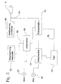
- FIG. 5 shows a circuit arrangement which makes possible a first possibility, namely an optical indication of the operating states of the UV tube 2.
- a first signal lamp 57 is connected to a first output of the switch 56.
- a second signal lamp 58 is connected to a second output of the switch 56.
- the first signal lamp 57 may be green in the present case and indicates the operating state of the UV tube 2 during which the instruments 4 are sterilized with the prescribed intensity of UV light.
- the second signal lamp 58 may be red in the present case and indicates that operating condition of the UV tube 2 during which the intensity of the emitted UV light is below the prescribed intensity.
- the aforementioned lamps 57 and 58 may be implemented as a single and per se known diode 95 (FIG. 3), which may be driven in two different ways. Depending on the type of control, this diode 95 may light up green or red.
- the diode 95 is mounted on the top of the carrier 20 and it is directed upwards. In the top wall 80 of the front cover 1, a corresponding opening 96 is executed. Through this opening 96, the diode 95 can be observed with which color it lights when switching between green and red. As long as the intensity of UV light below is the threshold level in the block "monitoring intensity" 54, burns the red lamp 58. After the intensity of the UV light has exceeded the threshold level, the green lamp burns 57th
- the green lamp 57 is connected to the first output of the changeover switch 56.
- a sleep switch 76 To the second output of the switch 56, one of the inputs of a sleep switch 76 is connected. A second input of the sleep switch 76 is connected via a control line 65 to the feed line 64 and thus also to the output of the device "control UV tube” 49.
- a first input of a breaker 77 is connected to the output of the red lamp 58 is connected.
- a timer 78 is connected to the output of the sleep switch 76, whose output is connected to a control input of the breaker 77.
- the supply of the UV tube 2 is broken off via the feed line 64 and it goes out.
- the level of the signal in the device "monitoring intensity" 54 drops below the threshold level provided, so that the switch 56 switches from the green lamp 57 to its second output, to which the first input of the sleep switch 76 is now connected instead of the red signal lamp 58 , Without this switch 76, the red signal lamp 58 would now continue to shine ununfierbrochen.
- the absence of the signal on the feed line 64 and thus also at the second input of the sleep switch 76 acts so that the sleep switch 76, the power of the red signal lamp 58th interrupts with energy and the red lamp 58 also goes out or does not start to light up.
- the failure of the UV tube 2 during operation, i. during a degermination process, is also recognized by the control electronics 10.
- the light sensor 44 no longer receives light from the UV tube 2.
- the intensity monitor 54 thus receives no signal from the light sensor 44, so that the level at the input of the intensity monitor 54 is below the said switching threshold.
- the intensity monitor 54 passes a corresponding signal to the switch 56, which causes the switch 56 to switch from the output "green light” 57 to its second output, namely, to the first input of the sleep switch 76.
- the voltage on the feed line 64 to the UV tube 2 remains in this case, however, because the voltage on the tube 2 is still applied. This is without regard to whether the tube 2 is defective or not. Consequently, this voltage is also at the second input of the sleep switch 76th
- the supply voltage is now at the second input of the sleep switch 76.
- the sleep switch 76 is designed to send a signal to a clock member 79 which causes the breaker 77 to supply the power to the red lamp 58 periodically interrupt.
- the flashing red light 58 signals the user of the device that the UV tube is defective and that it must be replaced.
- the red light 58 flashes until you pull the plug of the power supply unit 9 out of the device and thereby stops feeding the device.
- Fig. 6 shows a block diagram of a second embodiment for the signaling of the operating states of the present device.
- This block diagram is largely similar to the block diagram of Fig. 5.
- an acoustic signaling device 59 is connected to a (further) output of the sleep switch 56.
- This acoustic signaling device 59 may have a loudspeaker (not shown).
- the acoustic signaling can be done via a signal tone generator or a speech synthesizer with predetermined voice sequences.
- the same can also be equipped with a thermostat (not shown), which the UV light source switched on when exceeding a predetermined temperature, in particular in the interior of the housing 1.
- the connection of the thermostat is also designed so that this UV tube re-starts after the temperature sang below the threshold of danger.
- the device is characterized by a minimal power consumption and works in the safe for bathrooms low voltage range.
- This described device for germ-freeing and germ-free toothbrushes is not only intended for private households, but it can also be used in dental practices and hotel rooms. It is within the scope of the invention to use the device described or a similarly constructed device for germ-free and germ-free of other instruments that are used for the treatment or care of the human or animal body. In addition to medical or dental instruments, hairdressing instruments such as razors and the like as well as hand and foot care instruments may be considered. As a result, the UV radiation source switches on automatically during a movement process within the housing or the receptacle, whereby the sterilization is initiated.
- the control device is advantageously equipped with a counter which automatically switches off the switched-on UV light source after a predetermined time, for example after one hour.
Landscapes
- Health & Medical Sciences (AREA)
- Epidemiology (AREA)
- Life Sciences & Earth Sciences (AREA)
- Animal Behavior & Ethology (AREA)
- General Health & Medical Sciences (AREA)
- Public Health (AREA)
- Veterinary Medicine (AREA)
- Apparatus For Disinfection Or Sterilisation (AREA)
- Electrical Discharge Machining, Electrochemical Machining, And Combined Machining (AREA)
- Eye Examination Apparatus (AREA)
- Physical Water Treatments (AREA)
Abstract
Description
Die vorliegende Erfindung betrifft eine Vorrichtung zum Entkeimen von Instrumenten, insbesondere von Zahnbürsten, durch ultraviolette Strahlung, welche durch eine Strahlungsquelle erzeugt werden kann, wobei diese Vorrichtung so ausgeführt ist, dass der Betrieb der Strahlungsquelle überwacht werden kann, mit einem Innenteil, welcher eine längliche Hinterwand aufweist, über welche der Innenteil an einer Wand angebracht sein kann, und mit einem Gehäuse, welches dem Innenteil zugeordnet sein kann.The present invention relates to a device for sterilizing instruments, in particular toothbrushes, by ultraviolet radiation, which can be generated by a radiation source, this device being designed so that the operation of the radiation source can be monitored, with an inner part, which an elongated Rear wall, via which the inner part may be attached to a wall, and with a housing which may be associated with the inner part.
In
Die Aufgabe der vorliegenden Erfindung ist, diese sowie noch weitere Nachteile des Standes der Technik zu beseitigen.The object of the present invention is to eliminate these and other disadvantages of the prior art.
Diese Aufgabe wird bei der Vorrichtung der eingangs genannten Gattung erfindungsgemäss so gelöst, wie dies im kennzeichnenden Teil des Patentanspruchs 1 definiert ist.This object is achieved according to the invention in the device of the type mentioned above, as defined in the characterizing part of patent claim 1.
Nachstehend werden Ausführungsformen der vorliegenden Erfindung anhand der beiliegenden Zeichnungen näher erläutert. Es zeigt:
- Fig. 1 perspektivisch die vorliegende Vorrichtung mit einem Frontdeckel,
- Fig. 2 perspektivisch die Vorrichtung aus Fig. 1, bei welcher der Frontdeckel auf seiner Frontwand liegt und bei welcher ein Innenteil der Vorrichtung aufrecht stehend dargestellt ist,
- Fig. 3 in einem vertikalen Längsschnitt eine Platte des Innenteiles aus Fig. 2, welche den elektronischen Teil der vorliegenden Vorrichtung trägt,
- Fig. 4 ein Blockschaltbild einer ersten Ausführung des elektronischen Teiles der vorliegenden Vorrichtung,
- Fig. 5 ein Blockschaltbild eines Abschnittes des elekronischen Teiles, welcher zu einer ersten Art der Signalisieren der Arbeitsweise der vorliegenden Vorrichtung ausgeführt ist,
- Fig. 6 ein Blockschaltbild eines Abschnittes des elektronischen Teiles, welcher zu einer zweiten Art der Signalisierung der Arbeitsweise der vorliegenden Vorrichtung ausgeführt ist,
- Fig. 7 ein Blockschaltbild einer zweiten Ausführung des elektronischen Teiles der vorliegenden Vorrichtung,
- Fig. 8 in einem vertikalen Schnitt einen Halteeinrichtung für die Instrumente,
- Fig. 9 perspektivisch einen Grundkörper der Halteeinrichtung aus Fig. 8 und
- Fig. 10 perspektivisch einen Kamm der Halteeinrichtung.
- 1 is a perspective view of the present device with a front cover,
- 2 shows in perspective the device of FIG. 1, in which the front cover lies on its front wall and in which an inner part of the device is shown standing upright,
- 3 shows in a vertical longitudinal section a plate of the inner part of FIG. 2, which carries the electronic part of the present device, FIG.
- 4 is a block diagram of a first embodiment of the electronic part of the present device;
- Fig. 5 is a block diagram of a portion of the electronic part which is adapted to a first mode of signaling the operation of the present apparatus;
- Fig. 6 is a block diagram of a portion of the electronic part which is adapted to a second way of signaling the operation of the present apparatus;
- 7 is a block diagram of a second embodiment of the electronic part of the present apparatus;
- 8 shows in a vertical section a holding device for the instruments,
- 9 is a perspective view of a main body of the holding device from FIG. 8 and FIG
- Fig. 10 in perspective a comb of the holding device.
Die vorliegende Entkeimungsvorrichtung umfasst unter anderem ein optisch ansprechendes längliches Gehäuse 1 (Fig. 1 und 2), welches vorzugsweise aus einem Kunststoff ist. Dieses Gehäuse wird im Nachstehenden auch als Frontdeckel 1 der vorliegenden Vorrichtung bezeichnet. Dieses Gehäuse 1 weist, wie dies aus Fig. 1 und 2 ersichtlich ist, eine Oberwand 80, Seitenwände 81 und 82, eine Frontwand 83 und eine Bodenwand 84 auf. In der Oberwand 80 ist eine Reihe von Öffnungen 3 ausgeführt, welche sich in der Längsrichtung des Gehäuses 1 erstreckt. Durch die Öffnungen 3 können die zu entkeimenden Instrumente, im vorliegenden Fall sind dies Zahnbürsten 4, hindurchgesteckt werden. In Fig. 1 ist auch ein Stecknetzgerät 9 dargestellt, welches über ein Kabel 8 an den elektrischen Teil der vorliegenden Vorrichtung angeschlossen ist.The present degermination device comprises inter alia a visually appealing elongate housing 1 (Figures 1 and 2), which is preferably made of a plastic. This housing will also be referred to below as the front cover 1 of the present device. As can be seen in FIGS. 1 and 2, this housing 1 has an
Die vorliegende Entkeimungsvorrichtung umfasst ferner einen Innenteil 7 (Fig. 2), an welchem das Gehäuse 1 schwenkbar angeschlossen ist. Der Innenteil 7 weist einen im wesentlichen planen Grundkörper 85 auf. Dieser Grundkörpers 85 stelle eine Wand dar, welche die Hinterwand der Vorrichtung darstellt. Über diese Hinterwand 85 kann die Vorrichtung beispielsweise an einer Zimmerwand angebracht sein. An die jeweilige Endkante der länglichen Hinterwand 85 schliesst sich je eine Wange 25 an, welche senkrecht zur Ebene der Hinterwand 85 stehen und sich von dieser Hinterwand 85 nach vorne erstrecken. Zwischen den Wangen 25 erstreckt sich eine Trennwand 33, welche sich in einem Abstand von der Hinterwand 85 befindet und welche zur Hinterwand 85 parallel verläuft.The present degermination device further comprises an inner part 7 (FIG. 2) to which the housing 1 is pivotally connected. The
An der Aussenseite der jeweiligen Wange 25 ist je ein Scharnier 38 vorhanden (Fig. 2). Die Scharniere 38 ermöglichen den bereits erwähnten schwenkbaren Anschluss des Frontdeckels 1 an den Innenteil 7. Das jeweilige Scharnier 38 weist im dargestellten Beispiel einen Zapfen auf, welcher an der Aussenseite der betreffenden Wange 25 des Innenteiles 7 angeformt ist, sowie eine diesen Zapfen aufnehmen Öffnung in einer der Seitenwände 81 bzw. 82 des am Innenteil 7 wegschwenkbar angebrachten Frontdeckels 1. Je eines dieser Scharniere 38 wirkt somit zwischen der Aussenseite einer der Innenteilwangen 25 und einer der Seitenwände 81 bzw. 82 des Gehäuses 1. In Fig. 1 ist das Gehäuse 1 auf dem Innenteil 7 eingeschwenkt und eingerastet dargestellt.On the outside of the
Im Hohlraum bzw. im Aufnahmeschacht 35, welcher zwischen der Hinterwand 85 des Innenteiles 7 und der Trennwand 33 vorhanden ist, und etwa in der Mitte der Höhe der Wangen 25 ist ein Träger 20 (Fig. 3) für den elektrischen Teil 10 der vorliegenden Vorrichtung im Innenteil 7 einrastbar angeordnet. Dieser Träger 20 weist einen im wesentlichen planen bzw. streifenförmigen Grundkörper 21 auf. Dieser Grundkörper 21 ist als eine Platine aus einem elektrisch isolierenden Material ausgeführt und er trägt die gesamte Elektronik einschliesslich der Steuerungseinrichtung 10 und der Lichtquelle 2.In the cavity or receiving well 35, which is present between the
In der Trennwand 33 ist eine längliche Öffnung 34 ausgeführt, welche sich parallel zur Lichtquelle 2 erstreckt. Durch diese Lichtöffnung 34 kann das von der Lichtquelle 2 abgestrahlte in jenen Bereich der vorliegenden Vorrichtung gelangen, wo sich die Instrumente 4 befinden. Im Bereich der jeweiligen Endpartie des Trägers 20 ist je ein Halter 23 (Fig. 2) angeordnet. Der jeweilige Halter 23 ist im dargestellten Fall als ein flaches Stück aus einem ebenfalls isolierenden Material ausgeführt. Dieses Materialstück 23 steht praktisch senkrecht zum Grundkörper 21 des Trägers 20 und er befindet sich oberhalb des Trägers 20 des Innenteiles 7.In the
Die vorliegende Entkeimungsvorrichtung umfasst ferner eine Halteeinrichtung 90 (Fig. 1, 8 und 9) für die Instrumente 4. Diese Halteeinrichtung 90 ist der Vorder- bzw. Aussenseite der Trennwand 33 des Innenteiles 7 in einer an sich bekannten Weise zugeordnet. Dies kann beispielsweise mit Hilfe von Führungen 27 (Fig. 2) erfolgen, von welchen je eine an der Innenseite der jeweiligen Wangen 25 angebracht ist. Die Halteeinrichtung 90 weist einen im Querschnitt im wesentlichen L - förmigen Grundkörper 91 mit den Schenkeln 92 und 93 auf. Der erste dieser L-Schenkel 92 verläuft praktisch horizontal und der zweite L-Schenkel 93 erstreckt sich vom ersten Schenkel 92 empor. Die einander gegenüberliegenden Randpartien des horizontalen Schenkels 92 können in die Führungen 27 eingeschoben werden.The present degermination device further comprises a holding device 90 (FIGS. 1, 8 and 9) for the
Im Uebergangsbereich zwischen den L-Schenkeln 92 und 93 ist eine längliche Wanne 94 vorhanden, welche sich auf dem unteren bzw. horizontalen L-Schenkel 92 befindet und welche sich praktisch zwischen den Wangen 25 erstreckt. Im jeweiligen Endbereich der Wanne 94 ist je eine schlitzartige Führung 29 vorhanden, welche sich vom Boden der Wanne 94 aufwärts, d.h. vertikal und praktisch parallel zum zweiten L-Schenkel 93 erstrecken. Diese Halteeinrichtung 90 umfasst ferner einen Kamm 17, dessen einander gegenüberliegenden Randpartien 32 in die jeweilige Führung 98 bzw. 99 eingerührt werden können.In the transition region between the L-
Folglich befindet sich dieser Kamm 17 in einem Abstand vom vertikalen L-Schenkel 93 und er verläuft praktisch parallel zu diesem Schenkel 93. Nach dem Einführen des Aufnahmekamms 17 in die Halteeinrichtung 90 wird diese Einrichtung 90 selbst über ihren horizontalen L-Schenkel 92 nach Art eines Einschubs der Trennplatte 33 zugeordnet, indem die Ränder des horizontalen L-Schenkels 92 in die Führungen 27 an den Wangen 25 eingeschoben werden.Consequently, this
Der Kamm 17 ist zur Aufnahme der zu entkeimenden Instrumente 4 bestimmt und ausgebildet. Im Kamm 17 sind von oben her vertikal verlaufende Einschnitte 19 ausgeführt (Fig. 1 und 10), deren Breite der Breite des Kopfes 5 einer Zahnbürste 4 entspricht. Zwischen den Einschnitten 19 befinden sich Zinken 22 des Kammes 17. Der jeweilige Einschnitt 19 öffnet sich gegen eine der Öffnungen 3 in der Oberwand 80 des Behälters 1 hin. Der Bürstenkopf 5 ist so orientiert, dass die Borsten desselben gegen die Aussenseite der Trennwand 33 gerichtet sind. In diesem Bereich ist die Trennwand des Innenteiles 7 mit einem Fenster 34 versehen. Der Griff 6 der Zahnbürsten 4 ragt durch die Öffnungen 3 aus dem Gehäuse 1 heraus. Der Abstand des Kammes 17 vom Grundkörper 91 entspricht etwa der Dicke des Griffes der Zahnbürste 4.The
Sollte die Dicke des Griffes des Instrumentes 4 erheblich sein, dann ist es zweckdienlich, den vertikalen L-Schenkel 93 der Halteeinrichtung 90 ebenfalls mit den im Zusammenhang mit dem Kamm bzw. Rechen 17 bereits beschriebenen Einschnitten 19 zu versehen (Fig. 10). In einem solchen Fall ist es zweckdienlich, wenn die Einschnitte 19 bzw. die Zinken 22 der Platte 93 mit den Einschnitten 19 bzw. Zinken 22 des Rechens 17 ausgerichtet sind bzw. mit diesen fluchten.Should the thickness of the handle of the
Die einander gegenüberliegenden Endabschnitte 24 des länglichen Trägers 20, welche an der Aussenseite der Halter 23 liegen, tragen je eine Buchse 42 bzw. 43, deren Längsachsen parallel zur Ebene des Grundkörpers 21 verlaufen. Diese Buchsen 42 und 43 sind für die Aufnahme eines handelsüblichen Steckers am Steckernetzteil 9 ausgeführt und sie öffnen sich in einander entgegengesetzten Richtungen, und zwar nach aussen hin. Wenn das Gehäuse 1 auf dem Innenteil 7 aufgeschwenkt ist, dann stehen die sich nach aussen hin öffnenden Mündungen 74 der Buchsen 42 und 43 bestimmten Stellen an den Seitenwänden 81 und 82 des Gehäuses 1 gegenüber. Diese Stellen an den Gehäusewänden 81 und 82 sind mit je einer entsprechenden Öffnung 40 bzw. 41 versehen. Diese Öffnungen 40 und 41 sind so ausgeführt, dass der Stecker des Steckernetzgerätes 9 durch die betreffende Öffnung 40 bzw. 41 hindurchgesteckt und in die betreffende Buchse 42 bzw. 43 eingesteckt werden kann.The opposite end portions 24 of the
Die Verwendung der zwei genannten Buchsen bietet den Vorteil, dass der Stecker des Netzgerätes 9 von jener Seite her in die vorliegende Vorrichtung eingeführt werden kann, welche unter den gegebenen Bedingungen als vorteilhafter erscheint. Ausserdem wirkt der eingesteckte Stecker auch als Sicherung. Einerseits wirkt er als Sicherung gegen ein unabsichtliches Öffnen der Vorrichtung und zweitens wirkt er als Sicherung gegen ein Öffnen der Vorrichtung, solange diese noch ans Netz angeschlossen ist.The use of the two sockets mentioned offers the advantage that the plug of the
Der elektrische Teil der vorliegenden Vorrichtung umfasst unter anderem auch einen Sensor 16, welcher das Einführen eines Instrumentes 4 in das Gehäuse 1 detektieren soll. Dieser Sensor 16 ist im vorliegenden Fall als eine Lichtschranke ausgeführt. Diese Lichtschranke umfasst einen Lichtsender 161 und einen Lichtempfänger 162, zwischen welchen sich eine Lichtstrecke 163 befindet. Die Lichtschranke 16 kann auch mit Infrarotlicht arbeiten, sodass eine solche Lichtschranke einen Infrarotsender und einen Infrarotempfänger umfasst. Die Lichtquelle 161 der Lichtschranke 16 ist an einem der Halter 23 und der Lichtempfänger 162 der Lichtschranke 16 ist am anderen Halter 23 befestigt, und zwar in einem Abstand oberhalb der Platine 20. Dieser Abstand ist grösser als die Länge des Kopfes 5 der Zahnbürste 4. Die Lichtquelle 161 und der Lichtempfänger 162 sind an je einer der Grossflächen der Halter 23 angebracht, welche einander zugewandt sind.Among other things, the electrical part of the present device comprises a
Wie bereits erwähnt, ist das Gehäuse bzw. der Deckel 1 am U-förmigen Innenteil 7 schwenkbar angebracht. Während dem Betrieb der vorliegenden Einrichtung umgibt bzw. verdeckt der Frontdeckel 1 den Innenteil 7. Die Lichtschranke 16 ist oberhalb jenem Raum angeordnet, in welchem sich die Köpfe der in die Vorrichtung eingeführten Zahnbürsten 4 während der Entkeimung befinden. Die Lichtschranke 16 ist zugleich vor dem Kamm 17 so angeordnet, dass die Borsten der Köpfe 5 der Zahnbürsten 4 den Lichtstrahl 163 zwischen der Lichtquelle 161 und dem Lichtempfänger 162 der Lichtschranke 16 vorübergehend unterbrechen, wenn eine Zahnbürsten 4 durch eine der Öffnungen 3 des Dekkels 1 in das Innere dieser Vorrichtung eingeführt wird.As already mentioned, the housing or the cover 1 is pivotally mounted on the U-shaped
Die Lichtquelle 2 der vorliegenden Vorrichtung ist als eine ultraviolette Strahlen erzeugende Quelle ausgeführt. Im vorliegenden Fall handelt es sich um eine UV-C Röhre. Auf der Unterseite des Grundkörpers 21 des Träger 20 sind zwei Fassungen 22 für die Endpartien der UV-Röhre 2 befestigt. Diese Fassungen 22 sind so angeordnet, dass sich die UV-Lichtquelle 2 auf der Höhe der Borsten des Kopfes 5 der Zahnbürsten 4 befindet, welche in der Vorrichtung eingesteckt sind. Die Zahnbürsten 4 sind im Gehäuse 1 so gehalten, dass ihre Borsten zur UV-Lichtquelle 2 hin zeigen. Beim Einführen einer Zahnbürste in das Gehäuse 1 wird die Lichtschranke 16 betätigt und die UV-Lichtquelle 2 wird zum Betrieb während einer vorgegebenen Zeitspanne veranlasst. Die Zahnbürsten 4 oder andere Instrumente sind damit den ultravioletten Strahlen ausgesetzt und werden dadurch keimfrei gemacht bzw. keimfrei gehalten..The
Der elektrische Teil der vorliegenden Vorrichtung umfasst auch eine elektronische Steuerungseinrichtung 10, welche am Träger 20 ebenfalls angebracht ist und sich somit zusammen mit der Lichtquelle 2 auf der gemeinsamen Platine 21 befindet. In Fig. 4 ist die Topologie einer ersten Ausführung dieser Steuerungseinrichtung 10 der vorliegenden Vorrichtung schematisch dargestellt. Fig. 4 zeigt auch den bereits genannten Lichtsensor 16 für die Detektion der Instrumente 4. Die Instrumente 4 sind andererseits den Strahlen der UV-Röhre 2 ausgesetzt. Die Wege des Lichtes sind in Fig. 4 mit punktierten Linien angedeutet.The electrical part of the present device also includes an
Zwischen dem Träger 20 und der UV-Röhre 2 befindet sich ein streifenförmiger Reflektor 75. Dieser Reflektor 75 erstreckt sich zwischen den Fassungen 22 für UV-Röhre 2. Der Reflektor 75 ist aus einem elektrisch isolierendem Material und er hat zumindest eine verspiegelte, elektrisch leitende Oberfläche. Diese verspiegelte Oberfläche ist der UV-Röhre 2 zugewandt. In dem Reflektor 75 ist eine durchgehende Öffnung 87 ausgeführt. Diese Öffnung 87 befindet sich in jenem Bereich des Reflektors 75, wo der Tageslichtsensor 44 am Träger 20 angeordnet ist. Durch diese Öffnung strahlt die von der Röhre 2 ausgesendete Strahlung ungehindert auf den sich dahinter befindlichen Tageslichtsensor 44.Between the
An einen ersten Ausgang des Instrumentendetektors 16 ist eine Ansteuerungselektronik 49 für die UV-Röhre 2 über eine Leitung 60 angeschlossen. Auch diese Ansteuerungselektronik 49 wird aus dem Steckernetzgerät 9 gespiesen und sie dient zur Wandlung der Speisespannung vom Steckernetzteil 9 in die für den Betrieb der Röhre 2 notwendige elektrische Spannung mit der erforderlichen Frequenz. Diese Ansteuerungselektronik 49 ist über eine Speiseleitung 64 an die UV-Röhre 2 angeschlossen.To a first output of the
Die Schaltungsanordnung 10 umfasst ferner einen Lichtsensor 44. Dieser Lichtsensor 44 ist zur Erfassung von Licht vorgesehen, welches aus der UV-Röhre 2 austritt. Im vorliegenden Fall ist nicht nur die Tatsache von Bedeutung, ob die Röhre 2 UV-Licht überhaupt ausstrahlt, sondern auch, wie gross die Intensität dieses UV-Lichtes ist. Der Lichtsensor 44 ist somit auch so ausgeführt, dass der Ausgang desselben ein Signal entsprechend der Intensität des empfangenen UV-Lichtes abliefern kann. Im vorliegenden Fall ist der Sensor 44 derart, dass er normalerweise zur Messung von Tageslicht bestimmt ist. Im dargestellten Fall ist der Lichtsensor 44 in einer Öffnung in der Platine 21 eingelassen und zwar derart, dass seine Empfangsöffnung gegen die sich an der anderen Seite bzw. sich unterhalb der Platine 20 befindliche UV-Röhre 2 hin gerichtet ist (Fig. 3).The
Eine Messleitung 67 verbindet den Ausgang des Lichtsensors 44 mit dem Eingang einer Einrichtung 54 zur Überwachung der Intensität der UV-Strahlen. Die Intensität des von der Röhre 2 abgestrahlten UV-Lichtes ist nämlich gleich nach der Einschaltung der UV-Röhre 2 noch nicht so hoch, wie diese für die Entkeimung der Instrumente erforderlich ist. Die Intensität der UV-Strahlung erreicht erst nach einer bestimmten Verzögerung den für die Entkeimung erforderlichen Wert. Erst nachdem die Intensität der UV-Strahlung diesen Wert erreicht hat, beginnt die für die Entkeimung erforderliche Zeitspanne zu laufen. An einen der Ausgänge der Ueberwachungsvorrichtung 54 ist ein Umschalter 56 über eine Leitung 65 angeschlossen. Der Umschalter 56 ist unter anderem auch an eine Einrichtung zur Signalisierung des Betriebes der UV-Röhre 2 bzw. des Verlaufes des Entkeimungsprozesses angeschlossen. Diese Einrichtung ist im nachstehenden näher beschrieben.A measuring
Zur Bestimmung der Länge der genannten Bestrahlungszeitspanne dient eine weitere Gruppe der Steuerelektronik 10. Diese Gruppe umfasst eine Einrichtung 55 zur Vorgabe der Länge der Bestrahlungszeit, einen Oszilator bzw. eine Quelle von Impulsen 51 und einen an den Ausgang dieser Quelle 51 über eine Leitung 72 angeschlossenen Zähler 52, welcher über eine Signalleitung "Bestrahlungszeit" 73 an einen der Eingänge eines Komparators 53 angeschlossen ist. Der Betrieb des Zählers 52 wird über eine Leitung 61 gesteuert, welche einen zweiten Ausgang des Instrumentendeteldors 16 mit einem zweiten Eingang des Zählers 52 verbindet. Ein erster Ausgang des bereits erwähnten Umschalters 56 ist an einen ersten Eingang der Schaltung "Bestrahlugsvorgabe" 55 angeschlossen. Ein erster Ausgang der Vorgabeeinrichtung 55 ist an einen zweiten Eingang des Komparators 53 angeschlossen. Ein zweiter Ausgang der Bestrahlungsvorgabe 55 ist an einen Steuereingang des Oszillators 51 angeschlossen. Der Ausgang des Komparators 53 steuert über eine Leitung 66 den Betrieb der Ansteuerungseinrichtung 49 für die UV-Röhre 2. Im in Fig. 4 dargestellten Fall ist die Vorrichtung so ausgeführt, dass die Bestrahlungszeit in der Bestrahlungsvorgabe 55 fest eingestellt ist.To determine the length of said irradiation period, another group of
Beim Einschieben in die Vorrichtung unterbricht der Bürstenkopf 5 des ersten Instrumentes 4 den Lichtstrahl in der Lichtstrecke 163 des Instrumentendetektors 16. Dieser Instrumentendetektor 16 sendet einen Steuerimpuls über die Steuerleitung 60 zur Einrichtung "Ansteuerung UV-Röhre" 49. Gleichzeitig wird der Zähler 52 durch den Instrumentendetektor 16 über die Steuerleitung 61 auf Null gesetzt. Die Einrichtung "Ansteuerung UV-Röhre" 49 beginnt, die UV-Röhre 2 mit für den Betrieb dieser Röhre 2 erforderlichen Energie zu versorgen. Damit wird die UV-Röhre 2 gezündet und beginnt UV-Licht abzustrahlen. Der Lichtsensor 44 misst die Intensität der von der Röhre 2 abgegebenen Strahlung und legt sie auf die Messleitung 67. Die Einrichtung "Überwachung Intensität" 54 prüft über einen Schwellwertschalter, ob die Intensität für die Entkeimung der Instrumente 4 ausreichend ist.When inserted into the device of the brush head 5 of the
Normalerweise steigt die Intensität des durch die Röhre 2 abgestrahlten UV-Lichtes von einem Anfangswert, welcher unterhalb jenes Wertes liegt, der für die Entkeimung der Instrumente 4 erforderlich ist, innerhalb von wenigen Sekunden auf diesen vorgeschriebenen Wert. Während dieser Anfangsphase liegt der Wert des Signals am Ausgang des Lichtsensors 44 unterhalb einem Pegel, oberhalb welchem die Intensität des UV-Lichtes für die Entkeimung der Instrumente 4 ausreichend ist. Nach Ablauf dieser Anfangsphase, d.h. nachdem die Intensität des durch die Röhre 2 abgegebenen UV-Lichtes den vorgeschriebenen Pegelwert erreicht bzw. diesen überschritten hat, meldet dies die Einrichtung "Überwachung Intensität" 54 über die Signalleitung 65 dem Umschalter 56. Dieser Umschalter 56 gibt ein Signal an die Bestrahlungsvorgabe 55 ab, womit die fest eingestellte Bestrahlungszeit zu laufen beginnt.Normally, the intensity of the UV light emitted by the
Die Bestrahlungsvorgabe 55 liefert eine Information über die fest eingestellte Länge der erforderlichen Bestrahlungszeit an den Komparator 53 ab, und zwar in Form einer der gewünschten Länge der Bestrahlungszeit entsprechenden Anzahl von Impulsen. Der Oszillator 51 liefert Impulse an den Zähler 52, welcher diese kumuliert und welcher eine Auskunft über die Anzahl der vom Oszillator 51 empfangenen Impulse an den Komparator 53 liefert. Wenn die Anzahl der Impulse vom Zähler 52 der Anzahl der Impulse aus der Vorgabe 55 gleicht, liefert der Komparator 53 ein Signal an die Ansteuerung 49 ab, welche die UV-Röhre 2 ausser Betrieb setzt.The
Wird ein Instrument 4 in den Auffangbehälter 1 eingeführt, während sich andere und zuvor eingelegte Instrumente 4 schon im Entkeimungsprozess befinden, wird das Einführen des weiteren Instrumentes 4 in gleicher Weise wie die vorherigen Instrumente 4 vom Instrumentendetektor 16 durch einen Unterbruch in der Lichtstrecke 163 zwischen den Teilen 161 und 162 des Instrumentendetektors 16 erkannt. Mit einem Signal über die Steuerleitung 61 erfolgt eine Rückstellung des Zählers 52, sodass die vorgeschriebene Entkeimungszeit nach dem Einschieben eines weiteren Instrumentes 4 von neuem zu laufen beginnt. Dadurch erreicht die Entkeimungszeit für das zuletzt eingeschobene Instrument 4 den vollen von der "Bestrahlungszeit Vorgabe" 55 vorgegebenen Wert. Jene Instrumente 4, welche sich in der Vorrichtung bereits befinden, werden weiter und somit um so länger entkeimt.If an
Beispielsweise wegen einem länger dauernden Betrieb kann die Intensität des durch die Röhre 2 abgestrahlten Lichtes unter den für die Entkeimung erforderlichen Wert fallen. Die Röhre 2 brennt in einem solchen Fall weiter, weil sie über die Leitung 64 mit Energie versorgt wird. Der Benützer der Vorrichtung könnte es somit gar nicht merken, dass die Instrumente 4 nicht mehr ausreichend entkeimt werden. Um dies zu verhindern, ist die Einrichtung "Bestrahlungzeitvorgabe" 55 so ausgeführt, dass die Bestrahtungszeitvorgabe veränderbar ist. Zweckmässig ist, dass die Bestrahlungszeit entsprechend der Abnahme der Intensität des UV-Lichtes verlängert werden kann, und dass diese Verlängerung automatisch erfolgt.For example, because of prolonged operation, the intensity of the light emitted by the
Das Blockschaltbild einer so ausgeführten Vorrichtung ist in Fig. 7 gezeigt. Dieses Blockschaltbild unterscheidet sich vom Blockschaltbild gemäss Fig. 4 eigentlich nur darin, dass die Einrichtung "Überwachung Intensität" 54 einen noch zweiten Ausgang hat, welcher an einen zweiten Eingang der Einrichtung "Bestrahlungszeitvorgabe" 55 angeschlossen ist. Über eine diesbezügliche Leitung 68 erhält die Einrichtung " Bestrahlungszeitvorgabe" 55 die Auskunft über die aktuelle Intensität der von der Röhre 2 abgegebenen UV-Lichtes.The block diagram of such a device is shown in FIG. This block diagram differs from the block diagram of FIG. 4 actually only in that the device "monitoring intensity" 54 has a second output, which is connected to a second input of the device "irradiation timing" 55. Via a
Damit eine zur Entkeimung erforderliche, verlängerte Bestrahlungszeit bei abnehmender Intensität des durch die Röhre 2 abgegebenen Lichtes ermittelt werden kann, muss der Zusammenhang zwischen gemessener Strahlungsintensität und der verlängerten Bestrahlungszeit die Einrichtung " Bestrahlungszeitvorgabe" 55 eingegeben sein. Dieser Zusammenhang ist erfahrungsgemäss ein nichtlinearer Zusammenhang. Dieser Zusammenhang kann in einer Kennlinie modelliert. Diese Kennlinie ist in einem elektronischen Speicher derart gespeichert, dass zu jedem gemessen Wert der Strahlungsintensität eine dementsprechend verlängerte Bestrahlungszeit in der Einrichtung "Bestrahlungszeitvorgabe" 55 ermittelt werden kann.In order that a prolonged irradiation time required for sterilization can be determined with decreasing intensity of the light emitted by the
Das dazu geeignete elektronische Speicherwerk kann entweder in Analogtechnik oder in Digitaltechnik ausgeführt sein. Bei einer Ausführung in Digitaltechnik ist das elektronische Speicherwerk ein PROM, EPROM oder eine funktionell vergleichbare Komponente. Dabei ist der digitalisierte Messwert der "Überwachung Intensität" die Eingangsgrösse an einem Adressbus der Komponente. Die Ausgangsgrösse ist die der verminderten Strahlungsintensität entsprechend verlängerte Bestrahlungszeit. Die neue Bestrahlungszeit wird über die Steuerleitung 62 dem entsprechenden Eingang des Komparators 53 zur Steuerung des Betriebes der Einrichtung "Ansteuerung UV-Röhre" 49 zugeführt.The suitable electronic storage device can be designed either in analog technology or in digital technology. In a version in digital technology, the electronic storage device is a PROM, EPROM or a functionally comparable component. The digitized measured value of the "monitoring intensity" is the input quantity at an address bus of the component. The output variable is that of the reduced radiation intensity correspondingly prolonged irradiation time. The new irradiation time is supplied via the
Fig. 5 zeigt eine Schaltungsanordnung, welche eine erste Möglichkeit, nämlich eine optische Anzeige der Betriebszustände der UV-Röhre 2 ermöglicht. An einen ersten Ausgang des Umschalters 56 ist eine erste Signallampe 57 angeschlossen. An einen zweiten Ausgang des Umschalters 56 ist eine zweite Signallampe 58 angeschlossen. Die erste Signallampe 57 kann im vorliegenden Fall grün leuchten und sie zeigt jenen Betriebszustand der UV-Röhre 2 an, während welchem die Instrumente 4 mit der vorgeschriebenen Intensität des UV-Lichtes entkeimt werden. Die zweite Signallampe 58 kann im vorliegenden Fall rot leuchten und sie zeigt jenen Betriebszustand der UV-Röhre 2 an, während welchem die Intensität des abgestrahlten UV-Lichtes unterhalb der vorgeschriebenen Intensität liegt.5 shows a circuit arrangement which makes possible a first possibility, namely an optical indication of the operating states of the
Die genannten Lampen 57 und 58 können als eine einzige und an sich bekannte Diode 95 (Fig. 3) ausgeführt sein, welche in zwei verschiedenen Weisen angesteuert werden kann. Je nach der Art der Ansteuerung kann diese Diode 95 grün oder rot leuchten. Die Diode 95 ist auf der Oberseite des Trägers 20 montiert und sie ist empor gerichtet. In der Oberwand 80 des Frontdeckels 1 ist eine entsprechende Öffnung 96 so ausgeführt. Durch diese Öffnung 96 kann die Diode 95 beobachtet werden, mit welcher Farbe sie leuchtet, wenn sie zwischen grün und rot umschaltet. Solange die Intensität des UV-Lichtes unterhalb dem Schwellpegel im Block "Ueberwachung Intensität" 54 liegt, brennt die rote Lampe 58. Nachdem die Intensität des UV-Lichtes den Schwellpegel überschritten hat, brennt die grüne Lampe 57.The
Damit die rote Signallampe 58 nicht weiter brennt, nachdem der Entkeimungsvorgang ordentlich beendet worden ist, bedarf es weiterer Schaltungselemente in der vorliegenden Vorrichtung (Fig. 5).In order for the
Wie bereits erwähnt, ist die grüne Lampe 57 an den ersten Ausgang des Umschalters 56 angeschlossen. An den zweiten Ausgang des Umschalters 56 ist einer der Eingänge eines Ruheschalters 76 angeschlossen. Ein zweiter Eingang des Ruheschalters 76 ist über eine Steuerleitung 65 an die Speiseleitung 64 und somit auch an den Ausgang der Einrichtung "Ansteuerung UV-Röhre" 49 angeschlossen. An den Ausgang des Ruheschalters 76 ist ein erster Eingang eines Unterbrechers 77 angeschlossen, an dessen Ausgang die rote Lampe 58 angeschlossen ist. An den Ausgang des Ruheschalters 76 ist zugleich ein Zeitglied 78 angeschlossen, dessen Ausgang an einen Steuereingang des Unterbrechers 77 angeschlossen ist.As already mentioned, the
Ist die Entkeimung erfolgreich und ordentlich beendet worden, so wird die Speisung der UV-Röhre 2 über die Speiseleitung 64 abgebrochen und diese erlischt. Dabei sinkt der Pegel des Signales in der Einrichtung "Überwachung Intensität" 54 unter den vorgesehen Schwellpegel, sodass der Umschalter 56 von der grünen Lampe 57 auf seinen zweiten Ausgang umschaltet, an welchen der erste Eingang des Ruheschalters 76 jetzt anstelle der rote Signallampe 58 angeschlossen ist. Ohne diesen Ruheschalter 76 würde die rote Signallampe 58 jetzt ununfierbrochen weiter leuchten. Das Ausbleiben des Signals auf der Speiseleitung 64 und somit auch am zweiten Eingang des Ruheschalters 76 wirkt sich so aus, dass der Ruheschalter 76 die Speisung der roten Signallampe 58 mit Energie unterbricht und die rote Lampe 58 ebenfalls erlischt oder gar nicht beginnt zu leuchten.If the sterilization has been completed successfully and neatly, the supply of the
Der Ausfall der UV-Röhre 2 bei laufendem Betrieb, d.h. während einem Entkeimungsvorgang, wird von der Steuerelektronik 10 ebenfalls erkannt. Beim Ausfall der UV-Röhre 2 empfängt der Lichtsensor 44 kein Licht mehr von der UV-Röhre 2. Die Intensitätsüberwachung 54 erhält vom Lichtsensor 44 somit kein Signal, sodass der Pegel am Eingang der Intensitätsüberwachung 54 unterhalb der genannten Umschaltschwelle liegt. Die Intensitätsüberwachung 54 gibt ein entsprechendes Signal an den Umschalter 56 weiter, was den Umschalter 56 zum Umschalten vom Ausgang "grünes Licht" 57 zu seinem zweiten Ausgang, nämlich, zum ersten Eingang des Ruheschalters 76 veranlasst. Die Spannung auf der Speiseleitung 64 zur UV-Röhre 2 bleibt in diesem Fall jedoch erhalten, weil die Spannung an der Röhre 2 weiterhin angelegt ist. Dies nämlich ohne Rücksicht darauf, ob die Röhre 2 defekt ist oder nicht. Folglich liegt diese Spannung auch am zweiten Eingang des Ruheschalters 76.The failure of the
Im Unterschied zum vorher genannten Fall, befindet sich jetzt die Speisespannung am zweiten Eingang des Ruheschalters 76. Für diesen Fall ist der Ruheschalter 76 so ausgeführt, dass er ein Signal zu einem Taktglied 79 sendet, welches den Unterbrecher 77 veranlasst, die Speisespannung zur roten Lampe 58 periodisch zu unterbrechen. Durch das blinkende rote Licht 58 wird dem Benützer der Vorrichtung signalisiert, dass die UV-Röhre defekt ist und dass sie zu ersetzen ist. Das rote Licht 58 blinkt, bis man den Stecker des Stecknetzgerätes 9 aus der Vorrichtung herauszieht und dadurch die Speisung der Vorrichtung beendet.Unlike the previous case, the supply voltage is now at the second input of the
Fig. 6 zeigt ein Blockschaltbild einer zweiten Ausführungsmöglichkeit für die Signalisation der Betriebszustände der vorliegenden Vorrichtung. Dieses Blockschaltbild ähnelt weitest gehend dem Blockschaltbild aus Fig. 5. Im Unterschied zum Blockschaltbild gemäss Fig. 5 ist eine akustische Signaleinrichtung 59 an einen (weiteren) Ausgang des Ruheschalters 56 angeschlossen. Diese akustische Signaleinrichtung 59 kann einen Lautsprecher (nicht dargestellt) aufweisen. Die akustische Signalisierung kann dabei über einen Signaltongenerator oder einen Sprachsynthesizer mit vorgegebenen Sprachsequenzen erfolgen.Fig. 6 shows a block diagram of a second embodiment for the signaling of the operating states of the present device. This block diagram is largely similar to the block diagram of Fig. 5. In difference 5, an
In einer weiteren Ausbildung der Steuerungseinrichtung kann dieselbe auch mit einem Thermostat (nicht dargestellt) ausgestattet sein, der die eingeschaltete UV-Lichtquelle beim Überschreiten einer vorgegebenen Temperatur, insbesondere im Inneren des Gehäuses 1. Der Anschluss des Thermostaten ist ausserdem so gestaltet, dass dieser die UV-Röhre wieder in Betrieb nimmt, nachdem die Temperatur unter die Schwelle der Gefährdung sang.In a further embodiment of the control device, the same can also be equipped with a thermostat (not shown), which the UV light source switched on when exceeding a predetermined temperature, in particular in the interior of the housing 1. The connection of the thermostat is also designed so that this UV tube re-starts after the temperature sang below the threshold of danger.
Die Vorrichtung zeichnet sich durch einen minimalen Stromverbrauch aus und arbeitet im für Badezimmer gefahrlosen Niederspannungsbereich. Diese beschriebene Vorrichtung zum Keimfreimachen und Keimfreihalten von Zahnbürsten ist nicht nur für private Haushalte gedacht, sie kann vielmehr auch in zahnärztlichen Praxen und in Hotelzimmern verwendet werden. Es liegt im Rahmen der Erfindung, die beschriebene Vorrichtung oder eine ähnlich aufgebaute Vorrichtung zum Keimfreimachen und Keimfreihalten von anderen Instrumenten, welche der Behandlung oder der Pflege des menschlichen oder tierischen Körpers dienen, zu verwenden. In Frage kommen dabei neben ärztlichen bzw. zahnärztlichen Instrumenten auch Coiffeur-Instrumente, wie Rasiermesser und dergleichen sowie Hand- und Fusspflege-Instrumente. Hierdurch schaltet sich die UV-Strahlungsquelle bei einem Bewegungsvorgang innerhalb des Gehäuses bzw. des Aufnahmebehälters automatisch ein, wodurch die Entkeimung eingeleitet wird.The device is characterized by a minimal power consumption and works in the safe for bathrooms low voltage range. This described device for germ-freeing and germ-free toothbrushes is not only intended for private households, but it can also be used in dental practices and hotel rooms. It is within the scope of the invention to use the device described or a similarly constructed device for germ-free and germ-free of other instruments that are used for the treatment or care of the human or animal body. In addition to medical or dental instruments, hairdressing instruments such as razors and the like as well as hand and foot care instruments may be considered. As a result, the UV radiation source switches on automatically during a movement process within the housing or the receptacle, whereby the sterilization is initiated.
Durch eine wissenschaftliche Untersuchung der erfindungsgemässen Vorrichtung durch das Institut für Hygiene und Medizinische Mikrobiologie der Universität Bern wurde deren Wirksamkeit festgestellt. Aus einer Übernachtkultur von Escherichia coli wurde eine Keimsuspension hergestellt, die rund 5 x 10⁶ Keime pro ml enthielt. In diese Keimsuspension wurde dann eine Reihe von Zahnbürsten eingetaucht und anschliessend ausgeschlagen, um überschiessende Flüssigkeit mit Bakterien zu entfernen. Die so vorbehandelten Bürsten wurden dann entweder direkt in ein frisches und steriles Nährmedium gebracht, oder 10 Minuten, 20 Minuten oder 40 Minuten in die Vorrichtung bei brennender UV-Lichtquelle gestellt, wobei jeweils die Keimzahl in diesen Medien bestimmt wurde. Daraus ergab sich, dass nach 40 Minuten 98 % der Keime abgetötet waren. Auf Grundlage dieser Versuche ist deshalb die Steuerungseinrichtung vorteilhaft mit einem Zähler ausgestattet, welcher die eingeschaltete UV-Lichtquelle nach einer vorgegebenen Zeit, beispielsweise nach einer Stunde, selbsttätig abschaltet.By a scientific examination of the device according to the invention by the Institute of Hygiene and Medical Microbiology of the University Bern was found to be effective. From an overnight culture of Escherichia coli, a germ suspension was prepared containing approximately 5 x 10 6 germs per ml. A series of toothbrushes were then immersed in this germ suspension and then knocked out to remove overflowing liquid with bacteria. The thus pretreated brushes were then either placed directly into a fresh and sterile nutrient medium, or placed in the device with burning UV light source for 10 minutes, 20 minutes or 40 minutes, in each case the bacterial count was determined in these media. As a result, 98% of the germs were killed after 40 minutes. On the basis of these tests, therefore, the control device is advantageously equipped with a counter which automatically switches off the switched-on UV light source after a predetermined time, for example after one hour.
Claims (11)
- Device for the sterilizing of instruments (4), in particular of toothbrushes (6), by aid of ultra-violet radiation which can be produced by a radiation source (2), whereby this device is constructed in such a way, that the operation of the radiation source (2) can be monitored, having an inside part (7) which is provided with an elongated rear wall (85) over which this inside part (7) can be attached to a wall, and having a case (1), which is assigned to the inside part, characterized thereby that this inside part (7) shows cheeks (25), that each one of these cheeks (25) is assigned to the respective trailing edge of the elongated inside part (7) of the rear wall (85), whereby these cheeks (25) stand perpendicularly to the plane of this rear wall (85), that the case (1) has side walls (81,82), that the case (1) is assigned by aid of said side walls to the cheeks of the inside part (7) in a swingable and locking manner, that an elongated carrier (20) is provided for which is placed in the inside part (7), that the end sections (24) of this elongated carrier (20) is provided with a socket (42,43) for a plug of a power supply (9), that the side walls (81,82) of the case are provided with openings (40,41) and that these openings are carried out in such a way that the plug of a low voltage source (9) can pass through the respective opening (40,41) in the side wall of the case and that it can be plugged into the respective socket (42,43) when the case (1) is closed
- Device according to patent claim 1, characterized thereby that the longitudinal axes of the sockets (42,43) for the insertion of the plug of the low voltage source (9) extend parallel to the plane of the main body (21) of the carrier (20), that the sockets (42,43) are opened in opposite directions to each other, i.e. to the outside, and that each one of the openings (40, 41) in the side walls (81, 82) of the housing is in alignment with the mouth of one of the sockets (42, 43).
- Device according to patent claim 2, characterized thereby that a partition (33) is provided for, which is in a distance of the rear wall (85) of the inside part (7), that the elongated carrier (20) for the electrical part (10) is located in a receiving compartment (35) which is placed between the rear wall (85) of the inside part (7) and the partition (33), that the carrier (20) bears an elongated radiation source (2), that an elongated opening (34) is carried out in the partition (35) which extends parallel to the radiation source (2), and that a holding equipment (90) for the treated instruments (4) is provided for which is assigned to the opposite lying side of the partition (33).
- Device according to patent claim 3, characterized thereby that the basic body (91) of the holding equipment (90) has a basically L-shaped cross-section, that the equipment (90) further comprises an elongated tub (94) as well as a comb (17), that the tub (94) is placed on the horizontal arm (92), that a slot-like guide means (29) extends from the ground of the tub (94) upwards, that the edge parts (32) of the comb (17) which lay opposite to each other are set in the respective guide means (29), and that the comb (17) shows incisions (19), which run vertically downstairs, and that the respective incision (19) opens against one of openings (3), which are carried out in the upper wall (80) of the receptacle (1).
- Device according to patent claim 3, characterized thereby that a sensor (44) is assigned to the radiation source (2), which can monitor the operation of this radiation source (2) whereby said sensor can be a daylight sensor, that an equipment (54) for the measurement of the intensity of the radiation emitted from the radiation source (2) is attached to the exit of the sensor (44), that indicator lamps (57,58) and/or an acoustic signaler (59) are connected to separate exits of the equipment (54) for the measurement of the intensity of the radiation emitted from the radiation source (2) and that the electrical part (10) comprises a section, which serves for controlling of the operation time of the radiation source (2).
- Device according to patent claim 5, characterized thereby that an opening (96) is carried out in the upper wall (80) of the case (1) and that at least one of the indicator lamps (57,58) is placed below of this opening (80) so that the state of this indicator lamp (57,58) can be observed through the opening (80).
- Device according to patent claim 5, characterized thereby that the electrical part (10) comprises an oscillator (51) which is connected through a counter (52) onto one of the inputs of a comparator (53), that an equipment (55) for the determining of the time for the exposure to the radiation from the radiation source (2), that the output of this equipment (55) is connected to a second input of the comparator (53), that the output of the comparator (53) is connected to a second input of the control equipment (49), and that a second input of the instrument detector (16) is connected to a second control input of the counter (52).
- Device according to patent claim 7, characterized thereby that a second exit (68) of the equipment (54) for the monitoring of the intensity is connected to a control input of the equipment (55) for the determining of the radiation time.
- Device according to patent claim 7, characterized thereby that a detector (16) establishing the insertion of the instruments (4) into the device is provided for, that this detector (16) is assigned to the movement path of the instruments (4) which are inserted into the case (1), and that the output of this detector (16) is connected to an equipment (49) for the controlling of the radiation source (2).
- Device according to patent claim 5, characterized thereby that the sensor (16) is carried out as a light barrier, that this light barrier contains a phototransmitter (161) and a light detector (162) whereby a light path (163) is placed therebetween, that the source of light (161) and the light detector (162) are attached to a respective holder (23) which are placed in a distance of each other and above the board (20), and that the light barrier (16) is placed above that space in which the heads of the instruments (4) introduced into the device are located during the sterilization thereof.
- Device according to patent claim 1, characterized thereby that two holder (22) for the end portions of the elongated radiation source (2) are secured to the underside of the basic body (21) of the carrier (20), that these holders (22) are placed in such a way that the radiation source (22) is arranged on the heightof the heads (5) of the instruments (4) which are inserted in the device.
Applications Claiming Priority (3)
| Application Number | Priority Date | Filing Date | Title |
|---|---|---|---|
| CH4042003 | 2003-03-12 | ||
| CH4042003 | 2003-03-12 | ||
| PCT/CH2004/000145 WO2004080495A1 (en) | 2003-03-12 | 2004-03-11 | Device for sterilising instruments |
Publications (2)
| Publication Number | Publication Date |
|---|---|
| EP1601385A1 EP1601385A1 (en) | 2005-12-07 |
| EP1601385B1 true EP1601385B1 (en) | 2007-10-31 |
Family
ID=32968389
Family Applications (1)
| Application Number | Title | Priority Date | Filing Date |
|---|---|---|---|
| EP04719344A Expired - Lifetime EP1601385B1 (en) | 2003-03-12 | 2004-03-11 | Device for sterilising instruments |
Country Status (4)
| Country | Link |
|---|---|
| EP (1) | EP1601385B1 (en) |
| AT (1) | ATE376842T1 (en) |
| DE (1) | DE502004005360D1 (en) |
| WO (1) | WO2004080495A1 (en) |
Families Citing this family (3)
| Publication number | Priority date | Publication date | Assignee | Title |
|---|---|---|---|---|
| US9974873B2 (en) | 2010-05-10 | 2018-05-22 | Uv Partners, Inc. | UV germicidal system, method, and device thereof |
| WO2011143265A2 (en) | 2010-05-10 | 2011-11-17 | Ted Cole | Uv germicidal system, method, and device thereof |
| CA3169803A1 (en) | 2020-03-06 | 2021-09-10 | Uv Partners, Inc. | Uv disinfection platform |
Family Cites Families (4)
| Publication number | Priority date | Publication date | Assignee | Title |
|---|---|---|---|---|
| CH670568A5 (en) * | 1988-08-24 | 1989-06-30 | Anton Ameseder | |
| US6592816B1 (en) * | 1999-03-01 | 2003-07-15 | Johnson & Johnson Vision Care, Inc. | Sterilization system |
| US6429438B1 (en) * | 1999-07-12 | 2002-08-06 | Waterhealth International, Inc. | Ultraviolet light detector for liquid disinfection unit |
| DE29915857U1 (en) * | 1999-09-09 | 2000-01-05 | Gerhards, Matthias, 87527 Sonthofen | Toothbrush hygiene cabinet |
-
2004
- 2004-03-11 WO PCT/CH2004/000145 patent/WO2004080495A1/en active IP Right Grant
- 2004-03-11 EP EP04719344A patent/EP1601385B1/en not_active Expired - Lifetime
- 2004-03-11 AT AT04719344T patent/ATE376842T1/en not_active IP Right Cessation
- 2004-03-11 DE DE502004005360T patent/DE502004005360D1/en not_active Expired - Lifetime
Also Published As
| Publication number | Publication date |
|---|---|
| ATE376842T1 (en) | 2007-11-15 |
| EP1601385A1 (en) | 2005-12-07 |
| WO2004080495A1 (en) | 2004-09-23 |
| DE502004005360D1 (en) | 2007-12-13 |
Similar Documents
| Publication | Publication Date | Title |
|---|---|---|
| EP0356896B1 (en) | Sterilizing device for toilet instruments or medical instruments | |
| DE19618771C2 (en) | Water tap | |
| DE69002999T2 (en) | Dental care device. | |
| DE102008047069A1 (en) | Device with a spout for a liquid | |
| DE69812036T2 (en) | Dental hand-held device with a light source contained therein | |
| DE4232487A1 (en) | Tooth root canal diagnostic and measurement appts. | |
| DE60015328T2 (en) | BRAUSE HEAD WITH AN ULTRAVIOLETTLAMPE | |
| WO2019086598A1 (en) | Arrangement for storing and disinfecting toilet brushes | |
| DE102013202122A1 (en) | Device for performing deodorizing medical treatment e.g. Acne treatment, of human skin, has dosing device including source of radiation for creation and emission of electromagnetic radiation with wavelength between specific ranges | |
| EP1601385B1 (en) | Device for sterilising instruments | |
| DE102012224183A1 (en) | Device for cosmetic and/or medical treatment such as antimicrobial treatment of human skin, has actuating device which is provided for adjusting radiation intensity, and control unit is provided for controlling emission of radiation | |
| DE202021100344U1 (en) | Drawer with anti-epidemic effects | |
| DE3810065C1 (en) | Device for catching insects | |
| EP1112014A1 (en) | Toilet | |
| DE3635568A1 (en) | METHOD AND DEVICE FOR DISINFECTING AND STERILIZING THE FEEDING CIRCUIT OF DYNAMIC INSTRUMENTS FOR DENTAL DOCTORS | |
| DE202015004584U1 (en) | Sterilization cabin for toothbrushes | |
| DE3341797A1 (en) | Method and device for sterilising a quantity of liquid, in particular a quantity of water | |
| DE102006055113B3 (en) | Tunnel arrangement for hardening nail varnish comprises a housing and ultraviolet light sources for releasing an ultraviolet light spectrum suitable for cleaning and/or sterilizing | |
| EP0047418A1 (en) | Dark-room lamp | |
| DE102020112817A1 (en) | Mirror with disinfection unit | |
| DE102020119919A1 (en) | Irradiation module for furniture | |
| DE202006013664U1 (en) | Charging device for charging a toothbrush comprises a housing having a chamber for holding a toothbrush head and closed using a lid | |
| CH668189A5 (en) | DEVICE FOR GERM FREE MAKE AND KEIM KEEP CLEAR OF INSTRUMENTS THAT THE TREATMENT OF HUMAN OR ANIMAL body parts SERVE. | |
| EP4062946A2 (en) | Furniture with a furniture body and a movable furniture part | |
| DE29700911U1 (en) | Device for driving out animals |
Legal Events
| Date | Code | Title | Description |
|---|---|---|---|
| PUAI | Public reference made under article 153(3) epc to a published international application that has entered the european phase |
Free format text: ORIGINAL CODE: 0009012 |
|
| 17P | Request for examination filed |
Effective date: 20051011 |
|
| AK | Designated contracting states |
Kind code of ref document: A1 Designated state(s): AT BE BG CH CY CZ DE DK EE ES FI FR GB GR HU IE IT LI LU MC NL PL PT RO SE SI SK TR |
|
| AX | Request for extension of the european patent |
Extension state: AL LT LV MK |
|
| DAX | Request for extension of the european patent (deleted) | ||
| GRAP | Despatch of communication of intention to grant a patent |
Free format text: ORIGINAL CODE: EPIDOSNIGR1 |
|
| GRAS | Grant fee paid |
Free format text: ORIGINAL CODE: EPIDOSNIGR3 |
|
| GRAA | (expected) grant |
Free format text: ORIGINAL CODE: 0009210 |
|
| AK | Designated contracting states |
Kind code of ref document: B1 Designated state(s): AT BE BG CH CY CZ DE DK EE ES FI FR GB GR HU IE IT LI LU MC NL PL PT RO SE SI SK TR |
|
| REG | Reference to a national code |
Ref country code: GB Ref legal event code: FG4D Free format text: NOT ENGLISH |
|
| REG | Reference to a national code |
Ref country code: IE Ref legal event code: FG4D Free format text: LANGUAGE OF EP DOCUMENT: GERMAN |
|
| REG | Reference to a national code |
Ref country code: CH Ref legal event code: EP |
|
| REF | Corresponds to: |
Ref document number: 502004005360 Country of ref document: DE Date of ref document: 20071213 Kind code of ref document: P |
|
| NLV1 | Nl: lapsed or annulled due to failure to fulfill the requirements of art. 29p and 29m of the patents act | ||
| PG25 | Lapsed in a contracting state [announced via postgrant information from national office to epo] |
Ref country code: SE Free format text: LAPSE BECAUSE OF FAILURE TO SUBMIT A TRANSLATION OF THE DESCRIPTION OR TO PAY THE FEE WITHIN THE PRESCRIBED TIME-LIMIT Effective date: 20080131 Ref country code: ES Free format text: LAPSE BECAUSE OF FAILURE TO SUBMIT A TRANSLATION OF THE DESCRIPTION OR TO PAY THE FEE WITHIN THE PRESCRIBED TIME-LIMIT Effective date: 20080211 Ref country code: NL Free format text: LAPSE BECAUSE OF FAILURE TO SUBMIT A TRANSLATION OF THE DESCRIPTION OR TO PAY THE FEE WITHIN THE PRESCRIBED TIME-LIMIT Effective date: 20071031 |
|
| GBV | Gb: ep patent (uk) treated as always having been void in accordance with gb section 77(7)/1977 [no translation filed] | ||
| PG25 | Lapsed in a contracting state [announced via postgrant information from national office to epo] |
Ref country code: PL Free format text: LAPSE BECAUSE OF FAILURE TO SUBMIT A TRANSLATION OF THE DESCRIPTION OR TO PAY THE FEE WITHIN THE PRESCRIBED TIME-LIMIT Effective date: 20071031 Ref country code: SI Free format text: LAPSE BECAUSE OF FAILURE TO SUBMIT A TRANSLATION OF THE DESCRIPTION OR TO PAY THE FEE WITHIN THE PRESCRIBED TIME-LIMIT Effective date: 20071031 Ref country code: PT Free format text: LAPSE BECAUSE OF FAILURE TO SUBMIT A TRANSLATION OF THE DESCRIPTION OR TO PAY THE FEE WITHIN THE PRESCRIBED TIME-LIMIT Effective date: 20080331 Ref country code: BG Free format text: LAPSE BECAUSE OF FAILURE TO SUBMIT A TRANSLATION OF THE DESCRIPTION OR TO PAY THE FEE WITHIN THE PRESCRIBED TIME-LIMIT Effective date: 20080131 |
|
| REG | Reference to a national code |
Ref country code: IE Ref legal event code: FD4D |
|
| PG25 | Lapsed in a contracting state [announced via postgrant information from national office to epo] |
Ref country code: CZ Free format text: LAPSE BECAUSE OF FAILURE TO SUBMIT A TRANSLATION OF THE DESCRIPTION OR TO PAY THE FEE WITHIN THE PRESCRIBED TIME-LIMIT Effective date: 20071031 Ref country code: DK Free format text: LAPSE BECAUSE OF FAILURE TO SUBMIT A TRANSLATION OF THE DESCRIPTION OR TO PAY THE FEE WITHIN THE PRESCRIBED TIME-LIMIT Effective date: 20071031 |
|
| EN | Fr: translation not filed | ||
| PG25 | Lapsed in a contracting state [announced via postgrant information from national office to epo] |
Ref country code: RO Free format text: LAPSE BECAUSE OF FAILURE TO SUBMIT A TRANSLATION OF THE DESCRIPTION OR TO PAY THE FEE WITHIN THE PRESCRIBED TIME-LIMIT Effective date: 20071031 Ref country code: SK Free format text: LAPSE BECAUSE OF FAILURE TO SUBMIT A TRANSLATION OF THE DESCRIPTION OR TO PAY THE FEE WITHIN THE PRESCRIBED TIME-LIMIT Effective date: 20071031 |
|
| PLBE | No opposition filed within time limit |
Free format text: ORIGINAL CODE: 0009261 |
|
| STAA | Information on the status of an ep patent application or granted ep patent |
Free format text: STATUS: NO OPPOSITION FILED WITHIN TIME LIMIT |
|
| BERE | Be: lapsed |
Owner name: AMESEDER, ANTON Effective date: 20080331 |
|
| 26N | No opposition filed |
Effective date: 20080801 |
|
| PG25 | Lapsed in a contracting state [announced via postgrant information from national office to epo] |
Ref country code: MC Free format text: LAPSE BECAUSE OF NON-PAYMENT OF DUE FEES Effective date: 20080331 Ref country code: IE Free format text: LAPSE BECAUSE OF FAILURE TO SUBMIT A TRANSLATION OF THE DESCRIPTION OR TO PAY THE FEE WITHIN THE PRESCRIBED TIME-LIMIT Effective date: 20071031 Ref country code: FR Free format text: LAPSE BECAUSE OF FAILURE TO SUBMIT A TRANSLATION OF THE DESCRIPTION OR TO PAY THE FEE WITHIN THE PRESCRIBED TIME-LIMIT Effective date: 20080815 |
|
| REG | Reference to a national code |
Ref country code: CH Ref legal event code: NV Representative=s name: MOETTELI & ASSOCIES SARL Ref country code: CH Ref legal event code: PUE Owner name: CARMEN AMESEDER Free format text: AMESEDER, ANTON#LOEWENGARTENSTRASSE 11#CH-9400 RORSCHACH (CH) -TRANSFER TO- CARMEN AMESEDER#STEINWICHSLENSTRASSE 4#9052 NIEDERTEUFEN (CH) |
|
| PG25 | Lapsed in a contracting state [announced via postgrant information from national office to epo] |
Ref country code: GB Free format text: LAPSE BECAUSE OF FAILURE TO SUBMIT A TRANSLATION OF THE DESCRIPTION OR TO PAY THE FEE WITHIN THE PRESCRIBED TIME-LIMIT Effective date: 20071031 |
|
| PG25 | Lapsed in a contracting state [announced via postgrant information from national office to epo] |
Ref country code: GR Free format text: LAPSE BECAUSE OF FAILURE TO SUBMIT A TRANSLATION OF THE DESCRIPTION OR TO PAY THE FEE WITHIN THE PRESCRIBED TIME-LIMIT Effective date: 20080201 Ref country code: EE Free format text: LAPSE BECAUSE OF FAILURE TO SUBMIT A TRANSLATION OF THE DESCRIPTION OR TO PAY THE FEE WITHIN THE PRESCRIBED TIME-LIMIT Effective date: 20071031 |
|
| PG25 | Lapsed in a contracting state [announced via postgrant information from national office to epo] |
Ref country code: BE Free format text: LAPSE BECAUSE OF NON-PAYMENT OF DUE FEES Effective date: 20080331 Ref country code: FI Free format text: LAPSE BECAUSE OF FAILURE TO SUBMIT A TRANSLATION OF THE DESCRIPTION OR TO PAY THE FEE WITHIN THE PRESCRIBED TIME-LIMIT Effective date: 20071031 |
|
| PG25 | Lapsed in a contracting state [announced via postgrant information from national office to epo] |
Ref country code: CY Free format text: LAPSE BECAUSE OF FAILURE TO SUBMIT A TRANSLATION OF THE DESCRIPTION OR TO PAY THE FEE WITHIN THE PRESCRIBED TIME-LIMIT Effective date: 20071031 |
|
| PG25 | Lapsed in a contracting state [announced via postgrant information from national office to epo] |
Ref country code: LU Free format text: LAPSE BECAUSE OF NON-PAYMENT OF DUE FEES Effective date: 20080311 Ref country code: HU Free format text: LAPSE BECAUSE OF FAILURE TO SUBMIT A TRANSLATION OF THE DESCRIPTION OR TO PAY THE FEE WITHIN THE PRESCRIBED TIME-LIMIT Effective date: 20080501 |
|
| PG25 | Lapsed in a contracting state [announced via postgrant information from national office to epo] |
Ref country code: TR Free format text: LAPSE BECAUSE OF FAILURE TO SUBMIT A TRANSLATION OF THE DESCRIPTION OR TO PAY THE FEE WITHIN THE PRESCRIBED TIME-LIMIT Effective date: 20071031 |
|
| PGFP | Annual fee paid to national office [announced via postgrant information from national office to epo] |
Ref country code: CH Payment date: 20100917 Year of fee payment: 7 |
|
| PGFP | Annual fee paid to national office [announced via postgrant information from national office to epo] |
Ref country code: AT Payment date: 20100827 Year of fee payment: 7 Ref country code: DE Payment date: 20100902 Year of fee payment: 7 |
|
| PG25 | Lapsed in a contracting state [announced via postgrant information from national office to epo] |
Ref country code: IT Free format text: LAPSE BECAUSE OF NON-PAYMENT OF DUE FEES Effective date: 20080331 |
|
| REG | Reference to a national code |
Ref country code: CH Ref legal event code: PL |
|
| PG25 | Lapsed in a contracting state [announced via postgrant information from national office to epo] |
Ref country code: AT Free format text: LAPSE BECAUSE OF NON-PAYMENT OF DUE FEES Effective date: 20110311 |
|
| PG25 | Lapsed in a contracting state [announced via postgrant information from national office to epo] |
Ref country code: CH Free format text: LAPSE BECAUSE OF NON-PAYMENT OF DUE FEES Effective date: 20110331 Ref country code: DE Free format text: LAPSE BECAUSE OF NON-PAYMENT OF DUE FEES Effective date: 20111001 Ref country code: LI Free format text: LAPSE BECAUSE OF NON-PAYMENT OF DUE FEES Effective date: 20110331 |
|
| REG | Reference to a national code |
Ref country code: DE Ref legal event code: R119 Ref document number: 502004005360 Country of ref document: DE Effective date: 20111001 |