EP1601235A2 - Monitoring device suitable for flexible heating elements - Google Patents
Monitoring device suitable for flexible heating elements Download PDFInfo
- Publication number
- EP1601235A2 EP1601235A2 EP05006383A EP05006383A EP1601235A2 EP 1601235 A2 EP1601235 A2 EP 1601235A2 EP 05006383 A EP05006383 A EP 05006383A EP 05006383 A EP05006383 A EP 05006383A EP 1601235 A2 EP1601235 A2 EP 1601235A2
- Authority
- EP
- European Patent Office
- Prior art keywords
- monitoring device
- heating
- conductors
- conductor
- contact
- Prior art date
- Legal status (The legal status is an assumption and is not a legal conclusion. Google has not performed a legal analysis and makes no representation as to the accuracy of the status listed.)
- Granted
Links
Images

Classifications
-
- H—ELECTRICITY
- H05—ELECTRIC TECHNIQUES NOT OTHERWISE PROVIDED FOR
- H05B—ELECTRIC HEATING; ELECTRIC LIGHT SOURCES NOT OTHERWISE PROVIDED FOR; CIRCUIT ARRANGEMENTS FOR ELECTRIC LIGHT SOURCES, IN GENERAL
- H05B3/00—Ohmic-resistance heating
- H05B3/20—Heating elements having extended surface area substantially in a two-dimensional plane, e.g. plate-heater
- H05B3/34—Heating elements having extended surface area substantially in a two-dimensional plane, e.g. plate-heater flexible, e.g. heating nets or webs
- H05B3/342—Heating elements having extended surface area substantially in a two-dimensional plane, e.g. plate-heater flexible, e.g. heating nets or webs heaters used in textiles
-
- H—ELECTRICITY
- H05—ELECTRIC TECHNIQUES NOT OTHERWISE PROVIDED FOR
- H05B—ELECTRIC HEATING; ELECTRIC LIGHT SOURCES NOT OTHERWISE PROVIDED FOR; CIRCUIT ARRANGEMENTS FOR ELECTRIC LIGHT SOURCES, IN GENERAL
- H05B2203/00—Aspects relating to Ohmic resistive heating covered by group H05B3/00
- H05B2203/002—Heaters using a particular layout for the resistive material or resistive elements
- H05B2203/003—Heaters using a particular layout for the resistive material or resistive elements using serpentine layout
-
- H—ELECTRICITY
- H05—ELECTRIC TECHNIQUES NOT OTHERWISE PROVIDED FOR
- H05B—ELECTRIC HEATING; ELECTRIC LIGHT SOURCES NOT OTHERWISE PROVIDED FOR; CIRCUIT ARRANGEMENTS FOR ELECTRIC LIGHT SOURCES, IN GENERAL
- H05B2203/00—Aspects relating to Ohmic resistive heating covered by group H05B3/00
- H05B2203/002—Heaters using a particular layout for the resistive material or resistive elements
- H05B2203/005—Heaters using a particular layout for the resistive material or resistive elements using multiple resistive elements or resistive zones isolated from each other
-
- H—ELECTRICITY
- H05—ELECTRIC TECHNIQUES NOT OTHERWISE PROVIDED FOR
- H05B—ELECTRIC HEATING; ELECTRIC LIGHT SOURCES NOT OTHERWISE PROVIDED FOR; CIRCUIT ARRANGEMENTS FOR ELECTRIC LIGHT SOURCES, IN GENERAL
- H05B2203/00—Aspects relating to Ohmic resistive heating covered by group H05B3/00
- H05B2203/002—Heaters using a particular layout for the resistive material or resistive elements
- H05B2203/007—Heaters using a particular layout for the resistive material or resistive elements using multiple electrically connected resistive elements or resistive zones
-
- H—ELECTRICITY
- H05—ELECTRIC TECHNIQUES NOT OTHERWISE PROVIDED FOR
- H05B—ELECTRIC HEATING; ELECTRIC LIGHT SOURCES NOT OTHERWISE PROVIDED FOR; CIRCUIT ARRANGEMENTS FOR ELECTRIC LIGHT SOURCES, IN GENERAL
- H05B2203/00—Aspects relating to Ohmic resistive heating covered by group H05B3/00
- H05B2203/011—Heaters using laterally extending conductive material as connecting means
-
- H—ELECTRICITY
- H05—ELECTRIC TECHNIQUES NOT OTHERWISE PROVIDED FOR
- H05B—ELECTRIC HEATING; ELECTRIC LIGHT SOURCES NOT OTHERWISE PROVIDED FOR; CIRCUIT ARRANGEMENTS FOR ELECTRIC LIGHT SOURCES, IN GENERAL
- H05B2203/00—Aspects relating to Ohmic resistive heating covered by group H05B3/00
- H05B2203/014—Heaters using resistive wires or cables not provided for in H05B3/54
-
- H—ELECTRICITY
- H05—ELECTRIC TECHNIQUES NOT OTHERWISE PROVIDED FOR
- H05B—ELECTRIC HEATING; ELECTRIC LIGHT SOURCES NOT OTHERWISE PROVIDED FOR; CIRCUIT ARRANGEMENTS FOR ELECTRIC LIGHT SOURCES, IN GENERAL
- H05B2203/00—Aspects relating to Ohmic resistive heating covered by group H05B3/00
- H05B2203/017—Manufacturing methods or apparatus for heaters
-
- H—ELECTRICITY
- H05—ELECTRIC TECHNIQUES NOT OTHERWISE PROVIDED FOR
- H05B—ELECTRIC HEATING; ELECTRIC LIGHT SOURCES NOT OTHERWISE PROVIDED FOR; CIRCUIT ARRANGEMENTS FOR ELECTRIC LIGHT SOURCES, IN GENERAL
- H05B2203/00—Aspects relating to Ohmic resistive heating covered by group H05B3/00
- H05B2203/029—Heaters specially adapted for seat warmers
Definitions
- the present invention relates to a control and monitoring device for Prevention of overheating in flexible, textile surface heating elements, the at least two opposing contact conductors made of electrically conductive, uninsulated fibers or wires, between which several heating conductors extend, which are electrically connected to the contactors.
- From DE 4 101 290 and DE 19 831 574 are textile surface heating with at least two opposing contact strips of electrically conductive, uninsulated fibers or wires, between which more of an electrical Resistance material existing uninsulated heating conductors run, known.
- This type of surface heating elements are used primarily for seat heaters Used motor vehicles. Due to chemical and mechanical influences Like water, salt and movement on the seat, both the heating conductors and the Over time the contact ladder was attacked and destroyed locally.
- the mechanism of destruction is such that either the leaders of the Break contact strips by constant bending and compression and thus the Cross section of the contact strip tapers at the kink or the contact conductors are chemically attacked and decompose or the contact resistance from heat conductor to the contact conductor increases, so that increased heat output is produced. Also, the installation of a temperature sensor can be at the above Heating elements do not exclude the thermal problems on the contact conductors.
- a monitoring device of to develop the aforementioned type which prevents the heating element to or near the contact conductor gets so hot that the allowable thermal Limit temperature of the surrounding materials is exceeded.
- this object is achieved by a control and Monitoring device to prevent overheating in flexible, textile Surface heating elements consisting of at least two opposite ones Contact conductors consist of electrically conductive, uninsulated fibers or wires, between which several heating conductors extend, which with the contact conductors electrically are conductively connected, with an additional conductor is placed over the heating element and with a Evaluation unit is coupled to the with a current-voltage source for the heating conductors works together to prevent overheating.
- the additional conductor carries an insulation made of plastic or paint, which at intended use does not melt and thus prevents the Heat conductor and the additional conductor get electrical contact.
- a detection conductor as additional conductor two or monitored multiple contact strips, this from a contact strip along the Heating conductor is led to the next contact strip.
- claim 2 allow in particular the safe operation of Heating elements with metallic contact conductors and interconnected Heating conductors made of carbon fibers. Because these high temperatures are at fault locations at the Due to the high melting temperature of the Carbon fibers cause significant damage.
- the heating element according to Fig. 1 consists of a two-part textile Surface heating element 4, the upper part of a wavy heating conductor and whose lower part have a network-arranged heating conductor.
- the heating conductors are 8.1, 8.2 as CarbonMapleiter and the Additional conductor 1 formed as a rectilinear detection conductor.
- This arrangement but is not mandatory, but it can be modified by case by metallic heating conductors or other heating conductor materials.
- the additional ladder in However, they should be routed through the heating element at any angle remain outside the temperature sensing range, which in this example is lower terminal end of the contact conductor indicated by a temperature sensor 5 Is.
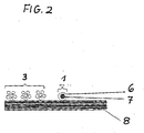
- a section of the heating element is shown in cross-sectional shape.
- the contact conductors 3 and the carbon heating conductors 8 are present as filaments.
- the salt conductor consists of a detection conductor 1 in its core of a steel filament. 7 which is provided with a coating material of a melt insulation 6.
- the monitoring device according to the invention thus consists of the additional conductors in the form of detection conductors 1 and the evaluation circuit 11. It is therefore relatively easy to introduce in a heating element and hardly causes additional costs. Due to its simple structure is the inventive Monitoring device is immune to interference and provides throughout the entire Lifetime of a panel heater safe protection against excessive Warming.
Abstract
Description
Die vorliegende Erfindung betrifft eine Kontroll- und Überwachungseinrichtung zur Vermeidung von Überhitzungen bei flexiblen, textilen Flächenheizelementen, die aus mindestens zwei sich gegenüberliegenden Kontaktleitern aus elektrisch leitfähigen, unisolierten Fasern oder Drähten bestehen, zwischen denen mehrere Heizleiter verlaufen, welche mit den Kontaktieltern elektrisch leitend verbunden sind.The present invention relates to a control and monitoring device for Prevention of overheating in flexible, textile surface heating elements, the at least two opposing contact conductors made of electrically conductive, uninsulated fibers or wires, between which several heating conductors extend, which are electrically connected to the contactors.
Aus der DE 4 101 290 sowie der DE 19 831 574 sind textile Flächenheizelemente mit
mindestens zwei sich gegenüberliegenden Kontaktleisten aus elektrisch leitfähigen,
unisolierten Fasern oder Drähten, zwischen denen mehrere aus einem elektrischem
Widerstandsmaterial bestehenden unisolierte Heizleitern verlaufen, bekannt.From
Diese Art von Flächenheizelementen werden in erster Linie für Sitzheizungen in Kraftfahrzeugen eingesetzt. Aufgrund von chemischen und mechanischen Einflüssen wie Wasser, Salz und Bewegung auf dem Sitz werden sowohl die Heizleiter als auch die Kontaktleiter im Laufe der Zeit angegriffen und lokal zerstört.This type of surface heating elements are used primarily for seat heaters Used motor vehicles. Due to chemical and mechanical influences Like water, salt and movement on the seat, both the heating conductors and the Over time the contact ladder was attacked and destroyed locally.
Werden Teile der Kontaktleiter zerstört, so ergeben sich Übergangswiderstände und damit lokale Wärmeentwicklungen entlang der Kontaktleisten die zu unzulässigen Erwärmungen des Heizelementes führen können.If parts of the contact conductors are destroyed, then contact resistance and so that local heat developments along the contact strips to impermissible Can cause heating of the heating element.
Die DE 4 101 290 und G 90 075 19 offenbart ein Heizelement dessen mechanische Lebensdauer durch Kontaktleisten mit wellenförmigem Verlauf verlängert werden soll, was das Problem einer Überhitzung zwar mindert aber nicht verhindern kann. Gegen korrosive Angriffe auf metallische Leiter sind Oberflächenbeschichtungen aus Silber und Zinn bekannt, welche aber durch Elektrokorrosion bei Anwesenheit von Salz und Feuchtigkeit in Verbindung mit elektrischen Spannungen zerstört werden. DE 4 101 290 and G 90 075 19 discloses a heating element whose mechanical Life is to be extended by contact strips with wave-shaped course, which reduces but does not prevent the problem of overheating. Versus Corrosive attacks on metallic conductors are surface coatings of silver and tin, which, however, by electrocorrosion in the presence of salt and Moisture in connection with electrical voltages are destroyed.
Der Mechanismus der Zerstörung läuft dabei so ab, dass entweder die Leiter der Kontaktleisten durch ständige Biegung und Stauchung brechen und sich damit der Querschnitt der Kontaktleiste an der Knickstelle verjüngt oder aber die Kontaktleiter werden chemisch angegriffen und zersetzen sich oder aber den Übergangswiderstand von Heizleiter auf die Kontaktleiter erhöht sich, so dass vermehrt Wärmeleistung erzeugt wird. Auch der Einbau eines Temperaturfühlers kann bei den oben genannten Heizelementen die thermischen Probleme an den Kontaktleitern nicht ausschließen.The mechanism of destruction is such that either the leaders of the Break contact strips by constant bending and compression and thus the Cross section of the contact strip tapers at the kink or the contact conductors are chemically attacked and decompose or the contact resistance from heat conductor to the contact conductor increases, so that increased heat output is produced. Also, the installation of a temperature sensor can be at the above Heating elements do not exclude the thermal problems on the contact conductors.
Daher ist es Aufgabe der vorliegenden Erfindung eine Überwachungsreinrichtung der eingangs genannten Art zu entwickeln, welche verhindert, dass das Heizelement an oder in der Nähe der Kontaktleiter so heiß wird, dass die zulässige thermische Grenztemperatur der umliegenden Materialien überschritten wird.It is therefore an object of the present invention, a monitoring device of to develop the aforementioned type, which prevents the heating element to or near the contact conductor gets so hot that the allowable thermal Limit temperature of the surrounding materials is exceeded.
Erfindungsgemäß wird diese Aufgabe gelöst durch eine Kontroll- und Überwachungseinrichtung zur Vermeidung von Überhitzungen bei flexiblen, textilen Flächenheizelementen, die aus mindestens zwei sich gegenüberliegenden Kontaktleitern aus elektrisch leitfähigen, unisolierten Fasern oder Drähten bestehen, zwischen denen mehrere Heizleiter verlaufen, welche mit den Kontaktleitern elektrisch leitend verbunden sind, wobei ein Zusatzleiter über die Heizleiter gelegt ist und mit einer Auswerteeinheit gekoppelt ist, die mit einer Strom-Spannungsquelle für die Heizleiter zur Vermeidung von Überhitzungen zusammen wirkt.According to the invention this object is achieved by a control and Monitoring device to prevent overheating in flexible, textile Surface heating elements consisting of at least two opposite ones Contact conductors consist of electrically conductive, uninsulated fibers or wires, between which several heating conductors extend, which with the contact conductors electrically are conductively connected, with an additional conductor is placed over the heating element and with a Evaluation unit is coupled to the with a current-voltage source for the heating conductors works together to prevent overheating.
Der Zusatzleiter trägt eine Isolierung aus Kunststoff oder Lack, welche bei bestimmungsmäßigem Gebrauch nicht schmilzt und somit verhindert, dass der Heizleiter und der Zusatzleiter elektrischen Kontakt bekommen. Es sind dabei auch Ausführungsformen denkbar, bei denen ein Detektionsleiter als Zusatzleiter zwei oder mehrere Kontaktleisten überwacht, wobei dieser von einer Kontaktleiste entlang der Heizleiter bis zur nächsten Kontaktleiste geführt wird.The additional conductor carries an insulation made of plastic or paint, which at intended use does not melt and thus prevents the Heat conductor and the additional conductor get electrical contact. There are also Embodiments conceivable in which a detection conductor as additional conductor two or monitored multiple contact strips, this from a contact strip along the Heating conductor is led to the next contact strip.
Entsteht irgendwo im Bereich des Detektionsleiters eine ausreichend hohe Temperatur im Bereich der Kontaktleiste oder der über die Kontaktleiste verlaufenden Heizleiter, so schmilzt die Isolierung und der Detektionsleiter bekommt elektrischen Kontakt mit den darunter liegenden nicht isolierten Heiz- und/oder Kontaktleitern.If there is a sufficiently high temperature somewhere in the area of the detection conductor in the area of the contact strip or the heat conductor extending over the contact strip, see above melts the insulation and the detection conductor gets electrical contact with the underlying non-insulated heating and / or contact conductors.
Diese elektrische Verbindung wird von der Auswerteeinheit, z.B. einem entfernten Steuergerät erfasst und das Heizelement wird vor Entstehung eines Brandes von der Strom-Spannungsquelle abgeschaltet. Vorzugsweise ist dieses Steuergerät auch gleichzeitig das Regelgerät für die Betriebstemperatur des Heizelements.This electrical connection is made by the evaluation unit, e.g. a distant one Detected control unit and the heating element is before the creation of a fire of the Current voltage source switched off. Preferably, this controller is also at the same time the control device for the operating temperature of the heating element.
Die Merkmale in Anspruch 2 ermöglichen insbesondere den sicheren Betrieb von Heizelementen mit metallischen Kontaktleitern und untereinander verbundenen Heizleitern aus Kohlefasern. Da diese hohe Temperaturen bei Fehlstellen an der Kontaktleiste erzeugen, kann es aufgrund der hohen Schmelztemperatur der Kohlefasern zu erheblichen Schäden kommen.The features of claim 2 allow in particular the safe operation of Heating elements with metallic contact conductors and interconnected Heating conductors made of carbon fibers. Because these high temperatures are at fault locations at the Due to the high melting temperature of the Carbon fibers cause significant damage.
Die Merkmale aus Anspruch 3 stellen sicher, dass der Zusatzleiter seinerseits den
mechanischen Knick- und Stauchbelastungen gewachsen ist und nicht im Bereich der
Kontaktleiste zerstört wird. Dies wird erfindungsgemäß durch einen elektrisch zwar nur
mäßig leitenden Stahlleiter erreicht, der aber hervorragende mechanische Stabilität
aufweist.The features of
Die Merkmale aus Anspruch 5 und 6 stellen sicher, dass die Isolierung nicht schon beim
Herstellungsprozess beschädigt wird, da in bestimmten Wirkverfahren spitze Nadeln
eingesetzt werden, die die Isolierung verletzen können. Speziell Kohlefaser werden von
den Nadeln durch die Isolierung hindurch bis zum Leiter gezogen, so dass ein
unerwünschter elektrischer Kontakt hergestellt wird.The features of
Die Merkmale aus Anspruch 7 und 8 verhindern eine Zerstörung des Zusatzleiters
durch mechanische Beanspruchungen.The features of
Im folgenden wird die Erfindung anhand mehrerer Ausführungsbeispiele erläutert. Es zelgen:
Figur 1- Draufsicht auf ein erfindungsgemäßes flexibles Heizelement
- Figur 2
- Darstellung eines Ausschnitts X des flexiblen Heizelements nach Fig. 1 als Querschnitt des Flächenheizelements im Bereich eines Kontaktleiters
- FIG. 1
- Top view of a flexible heating element according to the invention
- FIG. 2
- Representation of a section X of the flexible heating element according to Fig. 1 as a cross section of the surface heating element in the region of a contact conductor
Das Heizelement nach Fig. 1 besteht aus einem zweiteiligen textilen
Flächenheizelement 4, dessen oberer Teil einen wellenförmig verlaufenden Heizleiter
und dessen unterer Teil netzförmig angeordnete Heizleiter aufweisen.The heating element according to Fig. 1 consists of a two-part textile
An beiden Seitenrändern des flexiblen Heizelementes befindet sich ein Bereich von
Kontaktleitern 3.1, 3.2, die über entsprechende Zuführungsleitungen 9, 10 mit einer
Spannungsquelle (nicht dargestellt) verbunden sind.On both side edges of the flexible heating element is a range of
Contact conductors 3.1, 3.2, via
Parallel zu den Kontaktleitern 3.1, 3.2 zum Innenbereich des Heizelementes ist je ein
Zusatzleiter 1 in Form eines Detektionsleiters angeordnet. Im unteren Bereich des
Heizelementes, etwa auf der Höhe der Zufuhrleitungen 9, 10 werden die
Delektionsleiter zusammengeführt und mit einer Auswerteschaltung 11 verbunden.Parallel to the contact conductors 3.1, 3.2 to the interior of the heating element is ever one
Im vorliegenden Beispiel sind die Heizleiter 8.1, 8.2 als Carbonheizleiter und die
Zusatzleiter 1 als geradlinig verlaufende Detektionsleiter ausgebildet. Diese Anordnung
ist aber nicht zwingend, sondern sie kann fallweise auch abgewandelt werden durch
metallische Heizleiter oder andere Heizleitermaterialien. Auch können die Zusatzleiter in
jedem beliebigem Winkel über das Heizelement geführt werden, sie sollten jedoch
außerhalb des Temperaturfühlerbereichs bleiben, der im vorliegenden Beispiel im
unteren Anschlussende der Kontaktleiter durch einen Temperaturfühler 5 angedeutet
Ist.In the present example, the heating conductors are 8.1, 8.2 as Carbonheizleiter and the
Aus Fig. 2 ist ein Ausschnitt des Heizelementes in Querschnittsform dargestellt. Hier
liegen die Kontaktleiter 3 und die Carbonheizleiter 8 als Filamente vor. Der Zusalzleiter
besteht aus einem Detektionsleiter 1 der in seinem Kern aus einem Stahlfilament 7
besteht, das mit einem Überzugsmaterial aus einer Schmelzisolierung 6 versehen ist. From Fig. 2, a section of the heating element is shown in cross-sectional shape. Here
the
Wenn nun das Überzugsmaterial bei einer entsprechenden Temperatur der
Carbonheizleiter 8 schmilzt, kommen die Stahlfilamente 7 in Kontakt mit den unter
Strom stehenden Carbonheizleitern 8. Dadurch wird ein Signal zu der
Auswerteschaltung 11 gegeben, so dass die Stromzuführung für das Heizelement
unterbrochen werden kann. Damit ist die Gefahr einer Überhitzung des Heizelementes
beseitigt.Now, if the coating material at a corresponding temperature of the
Carbonheizleiter 8 melts, come the steel filaments 7 in contact with the below
Current standing Carbonheizleitern 8. This is a signal to the
Die erfindungsgemäße Überwachungseinrichtung besteht somit aus den Zusatzleitern
in Form von Detektionsleitern 1 und der Auswerteschaltung 11. Sie ist daher
verhältnismäßig leicht in ein Heizelement einzubringen und verursacht kaum
zusätzliche Kosten. Aufgrund ihres einfachen Aufbaus ist die erfindungsgemäße
Überwachungseinrichtung störunanfällig und bietet während der gesamten
Lebensdauer eines Flächenheizelementes einen sicheren Schutz gegen übermäßige
Erwärmung.The monitoring device according to the invention thus consists of the additional conductors
in the form of
Claims (10)
Applications Claiming Priority (2)
| Application Number | Priority Date | Filing Date | Title |
|---|---|---|---|
| DE102004026458A DE102004026458A1 (en) | 2004-05-29 | 2004-05-29 | Monitoring device for flexible heating elements |
| DE102004026458 | 2004-05-29 |
Publications (3)
| Publication Number | Publication Date |
|---|---|
| EP1601235A2 true EP1601235A2 (en) | 2005-11-30 |
| EP1601235A3 EP1601235A3 (en) | 2007-08-29 |
| EP1601235B1 EP1601235B1 (en) | 2011-01-12 |
Family
ID=34934455
Family Applications (1)
| Application Number | Title | Priority Date | Filing Date |
|---|---|---|---|
| EP05006383A Expired - Fee Related EP1601235B1 (en) | 2004-05-29 | 2005-03-23 | Monitoring device suitable for flexible heating elements |
Country Status (3)
| Country | Link |
|---|---|
| US (1) | US7067776B2 (en) |
| EP (1) | EP1601235B1 (en) |
| DE (2) | DE102004026458A1 (en) |
Cited By (4)
| Publication number | Priority date | Publication date | Assignee | Title |
|---|---|---|---|---|
| WO2009056794A1 (en) * | 2007-11-01 | 2009-05-07 | Heat Safe Cable Systems Limited | Self-regulating electrical heating cable |
| US10841980B2 (en) | 2015-10-19 | 2020-11-17 | Laminaheat Holding Ltd. | Laminar heating elements with customized or non-uniform resistance and/or irregular shapes and processes for manufacture |
| US10925119B2 (en) | 2015-01-12 | 2021-02-16 | Laminaheat Holding Ltd. | Fabric heating element |
| USD911038S1 (en) | 2019-10-11 | 2021-02-23 | Laminaheat Holding Ltd. | Heating element sheet having perforations |
Families Citing this family (7)
| Publication number | Priority date | Publication date | Assignee | Title |
|---|---|---|---|---|
| WO2005089019A2 (en) * | 2004-03-08 | 2005-09-22 | W.E.T. Automotive Systems Ag | Flat heating element |
| US20110068098A1 (en) * | 2006-12-22 | 2011-03-24 | Taiwan Textile Research Institute | Electric Heating Yarns, Methods for Manufacturing the Same and Application Thereof |
| JP5772978B2 (en) * | 2011-12-09 | 2015-09-02 | 日産自動車株式会社 | Cloth heater |
| CN104380838B (en) * | 2012-08-31 | 2016-06-22 | 株式会社美铃工业 | Heater and possess the fixing device of this heater, image processing system and heater |
| DE102015219019A1 (en) * | 2015-07-24 | 2017-01-26 | Johnson Controls Gmbh | HEATABLE HEADREST PILLOW |
| DE102017116489B4 (en) * | 2017-07-21 | 2023-03-16 | Phoenix Contact Gmbh & Co. Kg | Protective device for protecting an electrical consumer |
| DE102018210035A1 (en) * | 2018-06-20 | 2019-12-24 | Robert Bosch Gmbh | Textile element |
Citations (2)
| Publication number | Priority date | Publication date | Assignee | Title |
|---|---|---|---|---|
| US4547658A (en) * | 1984-06-13 | 1985-10-15 | Sunbeam Corporation | Multiple heat fusing wire circuit for underblankets |
| DE19831574A1 (en) * | 1998-07-14 | 2000-01-27 | Wet Automotive Systems Ag | Seat heater e.g. for car seat has switch for rapidly heating part of seat area with greater heating density |
Family Cites Families (8)
| Publication number | Priority date | Publication date | Assignee | Title |
|---|---|---|---|---|
| US3472289A (en) * | 1966-11-10 | 1969-10-14 | Brunswick Corp | Heater fabric |
| NL7315574A (en) * | 1973-11-14 | 1975-05-16 | Benoit De La Bretoniere Andre | TISSUE. |
| JPS62100968A (en) * | 1985-10-29 | 1987-05-11 | 東レ株式会社 | String heater element and manufacture of the same |
| DE9007519U1 (en) | 1990-06-28 | 1992-05-21 | Ruthenberg Gmbh Waermetechnik | |
| DE4101290C2 (en) | 1991-01-17 | 1994-11-03 | Ruthenberg Gmbh Waermetechnik | Electric surface heating element |
| JP3037525B2 (en) * | 1993-04-12 | 2000-04-24 | 松下電器産業株式会社 | Fever sheet |
| US6403935B2 (en) * | 1999-05-11 | 2002-06-11 | Thermosoft International Corporation | Soft heating element and method of its electrical termination |
| US6713733B2 (en) * | 1999-05-11 | 2004-03-30 | Thermosoft International Corporation | Textile heater with continuous temperature sensing and hot spot detection |
-
2004
- 2004-05-29 DE DE102004026458A patent/DE102004026458A1/en not_active Withdrawn
-
2005
- 2005-03-23 EP EP05006383A patent/EP1601235B1/en not_active Expired - Fee Related
- 2005-03-23 DE DE502005010827T patent/DE502005010827D1/en active Active
- 2005-05-24 US US11/137,354 patent/US7067776B2/en not_active Expired - Fee Related
Patent Citations (2)
| Publication number | Priority date | Publication date | Assignee | Title |
|---|---|---|---|---|
| US4547658A (en) * | 1984-06-13 | 1985-10-15 | Sunbeam Corporation | Multiple heat fusing wire circuit for underblankets |
| DE19831574A1 (en) * | 1998-07-14 | 2000-01-27 | Wet Automotive Systems Ag | Seat heater e.g. for car seat has switch for rapidly heating part of seat area with greater heating density |
Cited By (4)
| Publication number | Priority date | Publication date | Assignee | Title |
|---|---|---|---|---|
| WO2009056794A1 (en) * | 2007-11-01 | 2009-05-07 | Heat Safe Cable Systems Limited | Self-regulating electrical heating cable |
| US10925119B2 (en) | 2015-01-12 | 2021-02-16 | Laminaheat Holding Ltd. | Fabric heating element |
| US10841980B2 (en) | 2015-10-19 | 2020-11-17 | Laminaheat Holding Ltd. | Laminar heating elements with customized or non-uniform resistance and/or irregular shapes and processes for manufacture |
| USD911038S1 (en) | 2019-10-11 | 2021-02-23 | Laminaheat Holding Ltd. | Heating element sheet having perforations |
Also Published As
| Publication number | Publication date |
|---|---|
| EP1601235B1 (en) | 2011-01-12 |
| EP1601235A3 (en) | 2007-08-29 |
| US7067776B2 (en) | 2006-06-27 |
| DE102004026458A1 (en) | 2006-01-05 |
| DE502005010827D1 (en) | 2011-02-24 |
| US20050263519A1 (en) | 2005-12-01 |
Similar Documents
| Publication | Publication Date | Title |
|---|---|---|
| EP1601235B1 (en) | Monitoring device suitable for flexible heating elements | |
| DE60019343T2 (en) | ELECTRICAL CABLE CONTAINED WITH AN EARTH CAPTURE ON A NON-BRAIDED POLYMERIC GROUNDING PLAN | |
| DE102006026047B4 (en) | Heating element, seat and vehicle with such | |
| EP1961264B1 (en) | Flat heating element | |
| EP1835786B1 (en) | Planar heating element and process for manufacturing a planar heating element | |
| DE10066130B4 (en) | Textile heating device | |
| DE102005050459B3 (en) | Surface heating element for seat heater of motor vehicle seat, has conductor of higher conductivity running wave-like and meander-like and intersecting each of multiple steel filaments at several points | |
| EP1484945B1 (en) | Electrical heating cable or heating band | |
| WO2005089019A2 (en) | Flat heating element | |
| DE102013005901A1 (en) | Grounding cable i.e. rail grounding cable, for grounding e.g. handrails in station areas, has monitoring line surrounded by sleeve-like, pressure-resistant supporting element, which includes supporting wires that are coiled around line | |
| EP3592104B1 (en) | Heatable textile device | |
| EP2736304B1 (en) | Heating fabric | |
| DE19816816A1 (en) | Electrically heated surface heating element for heated vehicle seating or steering wheel | |
| EP2931004B1 (en) | Heating element | |
| DE102006027498B4 (en) | Mechanical protective hose system for electrical lines, in particular in motor vehicles | |
| DE102004045875A1 (en) | Element for heating surfaces contacted by passengers of a vehicle incorporates a zone with heater wires, wires for bringing electricity to the heater wires, and a contact zone for these wires | |
| EP1705957B1 (en) | Electrical heating conductor | |
| DE10055141B4 (en) | heating conductor | |
| DE102009016380B4 (en) | tissue | |
| DE202006004033U1 (en) | Heatable fabric as for floor coverings has spaced electrically conductive warp threads and a weft of resistive heating material with insulative cover except at contact points | |
| DE202006008796U1 (en) | Flat heating element | |
| EP3619781A1 (en) | Electrical component and method for producing it | |
| DE102004013625B4 (en) | Flat heating element | |
| DE102019131875B4 (en) | Electric panel heater, method of making an electric panel heater, self-limiting heating cable, and method of making a self-limiting heating cable | |
| DE102007054543A1 (en) | Textile flat structure for heating device of motor vehicle, has upper and lower positions formed in electrically conductive manner, and heating conductor comes out from upper position and extending through intermediate position |
Legal Events
| Date | Code | Title | Description |
|---|---|---|---|
| PUAI | Public reference made under article 153(3) epc to a published international application that has entered the european phase |
Free format text: ORIGINAL CODE: 0009012 |
|
| AK | Designated contracting states |
Kind code of ref document: A2 Designated state(s): AT BE BG CH CY CZ DE DK EE ES FI FR GB GR HU IE IS IT LI LT LU MC NL PL PT RO SE SI SK TR |
|
| AX | Request for extension of the european patent |
Extension state: AL BA HR LV MK YU |
|
| PUAL | Search report despatched |
Free format text: ORIGINAL CODE: 0009013 |
|
| AK | Designated contracting states |
Kind code of ref document: A3 Designated state(s): AT BE BG CH CY CZ DE DK EE ES FI FR GB GR HU IE IS IT LI LT LU MC NL PL PT RO SE SI SK TR |
|
| AX | Request for extension of the european patent |
Extension state: AL BA HR LV MK YU |
|
| 17P | Request for examination filed |
Effective date: 20080128 |
|
| AKX | Designation fees paid |
Designated state(s): DE FR IT SE |
|
| 17Q | First examination report despatched |
Effective date: 20080820 |
|
| GRAP | Despatch of communication of intention to grant a patent |
Free format text: ORIGINAL CODE: EPIDOSNIGR1 |
|
| GRAS | Grant fee paid |
Free format text: ORIGINAL CODE: EPIDOSNIGR3 |
|
| GRAA | (expected) grant |
Free format text: ORIGINAL CODE: 0009210 |
|
| AK | Designated contracting states |
Kind code of ref document: B1 Designated state(s): DE FR IT SE |
|
| REF | Corresponds to: |
Ref document number: 502005010827 Country of ref document: DE Date of ref document: 20110224 Kind code of ref document: P |
|
| REG | Reference to a national code |
Ref country code: DE Ref legal event code: R096 Ref document number: 502005010827 Country of ref document: DE Effective date: 20110224 |
|
| REG | Reference to a national code |
Ref country code: SE Ref legal event code: TRGR |
|
| PLBE | No opposition filed within time limit |
Free format text: ORIGINAL CODE: 0009261 |
|
| STAA | Information on the status of an ep patent application or granted ep patent |
Free format text: STATUS: NO OPPOSITION FILED WITHIN TIME LIMIT |
|
| 26N | No opposition filed |
Effective date: 20111013 |
|
| PG25 | Lapsed in a contracting state [announced via postgrant information from national office to epo] |
Ref country code: IT Free format text: LAPSE BECAUSE OF FAILURE TO SUBMIT A TRANSLATION OF THE DESCRIPTION OR TO PAY THE FEE WITHIN THE PRESCRIBED TIME-LIMIT Effective date: 20110112 |
|
| REG | Reference to a national code |
Ref country code: DE Ref legal event code: R097 Ref document number: 502005010827 Country of ref document: DE Effective date: 20111013 |
|
| REG | Reference to a national code |
Ref country code: FR Ref legal event code: PLFP Year of fee payment: 12 |
|
| REG | Reference to a national code |
Ref country code: FR Ref legal event code: PLFP Year of fee payment: 13 |
|
| REG | Reference to a national code |
Ref country code: FR Ref legal event code: PLFP Year of fee payment: 14 |
|
| PGFP | Annual fee paid to national office [announced via postgrant information from national office to epo] |
Ref country code: SE Payment date: 20200323 Year of fee payment: 16 |
|
| PGFP | Annual fee paid to national office [announced via postgrant information from national office to epo] |
Ref country code: FR Payment date: 20200319 Year of fee payment: 16 |
|
| PGFP | Annual fee paid to national office [announced via postgrant information from national office to epo] |
Ref country code: DE Payment date: 20210414 Year of fee payment: 17 |
|
| PG25 | Lapsed in a contracting state [announced via postgrant information from national office to epo] |
Ref country code: SE Free format text: LAPSE BECAUSE OF NON-PAYMENT OF DUE FEES Effective date: 20210324 Ref country code: FR Free format text: LAPSE BECAUSE OF NON-PAYMENT OF DUE FEES Effective date: 20210331 |
|
| REG | Reference to a national code |
Ref country code: DE Ref legal event code: R119 Ref document number: 502005010827 Country of ref document: DE |
|
| PG25 | Lapsed in a contracting state [announced via postgrant information from national office to epo] |
Ref country code: DE Free format text: LAPSE BECAUSE OF NON-PAYMENT OF DUE FEES Effective date: 20221001 |