EP1601067A1 - Befestigungsanordnung für ein Pumpmodul - Google Patents
Befestigungsanordnung für ein Pumpmodul Download PDFInfo
- Publication number
- EP1601067A1 EP1601067A1 EP04012845A EP04012845A EP1601067A1 EP 1601067 A1 EP1601067 A1 EP 1601067A1 EP 04012845 A EP04012845 A EP 04012845A EP 04012845 A EP04012845 A EP 04012845A EP 1601067 A1 EP1601067 A1 EP 1601067A1
- Authority
- EP
- European Patent Office
- Prior art keywords
- carrier
- pump module
- arrangement according
- counter
- module
- Prior art date
- Legal status (The legal status is an assumption and is not a legal conclusion. Google has not performed a legal analysis and makes no representation as to the accuracy of the status listed.)
- Granted
Links
Images
Classifications
-
- H—ELECTRICITY
- H01—ELECTRIC ELEMENTS
- H01S—DEVICES USING THE PROCESS OF LIGHT AMPLIFICATION BY STIMULATED EMISSION OF RADIATION [LASER] TO AMPLIFY OR GENERATE LIGHT; DEVICES USING STIMULATED EMISSION OF ELECTROMAGNETIC RADIATION IN WAVE RANGES OTHER THAN OPTICAL
- H01S3/00—Lasers, i.e. devices using stimulated emission of electromagnetic radiation in the infrared, visible or ultraviolet wave range
- H01S3/02—Constructional details
- H01S3/025—Constructional details of solid state lasers, e.g. housings or mountings
-
- H—ELECTRICITY
- H01—ELECTRIC ELEMENTS
- H01S—DEVICES USING THE PROCESS OF LIGHT AMPLIFICATION BY STIMULATED EMISSION OF RADIATION [LASER] TO AMPLIFY OR GENERATE LIGHT; DEVICES USING STIMULATED EMISSION OF ELECTROMAGNETIC RADIATION IN WAVE RANGES OTHER THAN OPTICAL
- H01S3/00—Lasers, i.e. devices using stimulated emission of electromagnetic radiation in the infrared, visible or ultraviolet wave range
- H01S3/09—Processes or apparatus for excitation, e.g. pumping
- H01S3/091—Processes or apparatus for excitation, e.g. pumping using optical pumping
- H01S3/094—Processes or apparatus for excitation, e.g. pumping using optical pumping by coherent light
- H01S3/0941—Processes or apparatus for excitation, e.g. pumping using optical pumping by coherent light of a laser diode
-
- H—ELECTRICITY
- H01—ELECTRIC ELEMENTS
- H01S—DEVICES USING THE PROCESS OF LIGHT AMPLIFICATION BY STIMULATED EMISSION OF RADIATION [LASER] TO AMPLIFY OR GENERATE LIGHT; DEVICES USING STIMULATED EMISSION OF ELECTROMAGNETIC RADIATION IN WAVE RANGES OTHER THAN OPTICAL
- H01S3/00—Lasers, i.e. devices using stimulated emission of electromagnetic radiation in the infrared, visible or ultraviolet wave range
- H01S3/02—Constructional details
- H01S3/04—Arrangements for thermal management
Definitions
- the present invention relates to an arrangement for fastening at least one Pump module on a support.
- the laser diode stacks are a consumable part and have to be degraded or can be replaced in the event of a defect. Usually either the laser diode stack alone or an entire assembly containing the Includes diode stack and simplified replacement, replaced. These Assembly may include a housing with optics and electronics and is used in the Hereafter referred to as pumping module.
- This object is achieved by an arrangement for attachment at least one pump module, which on a plant side a contact surface and terminals, on a support, which on a plant side Has at least one contact surface and mating connections, wherein a Holding device, the contact surface of the pump module in contact with the contact surface of the carrier to form a connection between terminals and Counter-connections holds.
- the pumping module preferably has its front in an insertion direction End both an exit window or an exit opening for a laser beam as Also, a pivot bearing and the carrier on a counter-pivot bearing on which the Pump module in the attached state attacks.
- the pivot bearing of the pumping module by a or several opposite the insertion direction open bearing recesses and the Counter-pivot bearing of the carrier formed by one or more axle journals.
- the pump module at its front end in the insertion direction a projection and the carrier a corresponding recess or vice versa on, with projection and recess in the attached state of the pump module without lateral play mesh.
- the counter-pivot bearing of the carrier in the insertion direction and / or at a distance to the contact surface of the carrier and / or about an axis perpendicular to The contact surface of the carrier is adjustable.
- the Counter-pivot bearing by means of a reference pumping module to a predetermined Position to be adjusted. It is essential that the laser beam of the attached Pump module in a spatially clearly defined relationship to the mechanical Stop of the carrier, i. to the counter-pivot bearing, is oriented. A readjustment omitted if a pump module with the same main axes oriented as the reference pumping module abuts the counter-pivot bearing.
- the terminals and Counter connections for electrical supply and / or for coolant supply and / or to the purge gas supply of the pump module and / or for data transmission intended are intended.
- the electricity, Coolant, purge gas, and data ports are designed to have no effect on the adjustment of the pump module have, as their separation surfaces parallel to Lie contact surface and so no predefinition of the beam axis of the pumping module he follows.
- the data exchange with the pump module is preferably via connector parts, the are floatingly mounted on the pump module and / or on the carrier, so that no Predefinition of the laser beam axis of the pumping module takes place.
- the power connection necessary for the operation of the diode laser stack is preferred realized via flat contacts, the corresponding contact surfaces on the carrier Contact, with the necessary force for pressing the flat contacts through the holding device is generated.
- the sealing surface for the Coolant connection is in a preferred embodiment of the pump module on Pump module and the carrier in relation to the level of the power supply and Data connections arranged lower level, so that when changing the Pump module no coolant on the electronics and / or the optics arrive can.
- the holding device for the pump module preferably comprises at least one Tension lever, which is mounted on the carrier or on the pump module and with its free End of the pump module or engages the carrier.
- the tensioned Tension lever the pivot bearing of the pump module against the counter-pivot bearing the support and the contact surface of the voltage applied to the counter-pivot bearing Pump module in contact with the contact surface of the carrier.
- the cocking lever can without Tool are actuated and clamped the pump module in a defined spatial position the carrier.
- the carrier has several, in particular fan-shaped, adjacent contact surfaces with counter connections and Jacobenklagern for receiving a respective pumping module on. It can the plurality of contact surfaces are arranged along a circular arc, in whose Focused on an optic, which the laser beams all on the carrier fastened pumping modules to a common laser beam merges.
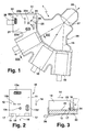
- the arrangement 1 shown in Fig. 1 is used for the attachment of four pumping modules 10 in a fan-shaped carrier 20.
- the pump modules 10 comprise diode laser stacks for pumping a high power solid state laser (not shown).
- the diode laser stacks are protected by the module housing from environmental influences (splash water, dust, contact, mechanical influences).
- the module housing is designed so that the diode laser stack with purging air can be kept dust-free, dry and solvent-free.
- a pump module 10 has on a contact side 11 a planar contact surface 12 and connections 13a-13d and at its front end in an insertion direction 14 an exit window 15 (FIG. 3) for a laser beam 16 of the diode laser stack and a pivot bearing 17 on.
- the pivot bearing 17 is formed by two counter to the insertion direction 14 open bearing recesses defining a parallel to the contact surface 12 and perpendicular to the insertion direction 14 extending pivot axis. Between the bearing recesses is a central projection 18 which is laterally spaced from the bearing recesses by a respective recess 19 .
- the exit window 15 may be open or closed with a window, for example in the form of a lens or a plane-parallel plate.
- the carrier 20 has on a contact side 21 for each pumping module 10, a flat contact surface 22 and mating connections 23a-23d and at its front end in the direction of insertion 14 a counter-pivot bearing 24 .
- the counter-pivot bearing 24 is formed by two axle journals, which are adjustable in the insertion direction 14 and at a distance from the contact surface 22 and / or about the axis 25 (double arrow) by means of adjusting screws (not shown). Between the axle journal is a recess 29.
- a retaining means is provided in the form of a tension lever 26 which is mounted on the carrier 20 and engages with its free end on the pump module 10th
- the pumping module 10 in Insertion direction 14 at an angle of about 5 ° to about 30 ° to the contact surface 22nd brought to the carrier 20 until the pivot bearing 17 on the counter-pivot bearing 24th is applied.
- the central projection 18 engages the pump module 10 in the recess 29 on the carrier 20 without lateral play, so that a lateral (i.e., axial) Moving the voltage applied to the counter-pivot bearing 24 pumping module 10th is prevented.
- the pump module 10 by means of the clamping lever the pivot axis of the bearings 17, 24 twisted and stretched until the contact surface 12th of the voltage applied to the counter-pivot bearing 24 pumping module 10 to form a Connection between the terminals 13a-13d and the mating terminals 23a-23d on the contact surface 22 of the carrier 20 is applied in parallel.
- the counter-pivot bearing 24 by means of a reference pumping module on the Adjustment screws has been adjusted in advance to a predetermined position deleted a readjustment, when the pumping module 10 to be fastened, the main axes its laser beam 16 is the same as the main axes of the reference pumping module are oriented.
- the tension lever is a force component in the direction of exiting laser beam 16 induced, with the pivot bearing 17 am Counter-pivot bearing 24 is present.
- the clamping lever is another Force component induced in the direction of the contact surface 22 of the carrier 20, with the the contact surface 12 rests against the contact surface 22 of the carrier 20.
- the cooling connection necessary for the operation of the diode laser stack is over two Supply lines realized. These contain on the pump module side the Connection 13d with two captive seals caused by the pivoting movement during insertion and locking of the pumping module 10 on flat sealing surfaces of Press counter connections 23d of carrier 20. The necessary for the sealing Contact pressure is applied by the clamping lever.
- the sealing surfaces of Counter connections 23d are on the carrier in a plane opposite the plane Power supply and data connections arranged lower level, so that when changing the pump module no coolant to the electronics and / or the optics can arrive.
- the power connection required to operate the diode laser stack becomes realized pump module side via two flat contacts 13b, the corresponding Contact surfaces 23 b contact the carrier 20.
- the necessary force for pressing the flat contacts 13b is also generated by the clamping lever.
- the data exchange is realized via a plug, whose on the pump module 10th or on the carrier 20 provided plug part 13a, 23a is floating, so that no predefinition of the beam axis of the exiting laser beam 16 takes place.
- a purge air connection is pump module side via a connection opening 13c with realized a seal on which a corresponding connection opening 23 c of the Carrier 20 presses. Due to this design of the interfaces (mechanical, electrically) and their arrangement exclusively on the contact side 11 of the Pump module 10, the pump module 10 changed without further aids become.
- the four abutment surfaces 22 of the carrier 20 are arranged along a circular arc, in the center of an optics 27 is arranged, which brings together the laser beams 16 of all pumping modules 10 to a common output laser beam 28 for pumping the high-power solid-state laser.
Landscapes
- Physics & Mathematics (AREA)
- Electromagnetism (AREA)
- Engineering & Computer Science (AREA)
- Plasma & Fusion (AREA)
- Optics & Photonics (AREA)
- Lasers (AREA)
- Compressor (AREA)
- Optical Couplings Of Light Guides (AREA)
Abstract
Description
- Fig. 1
- eine Draufsicht auf die erfindungsgemäße Anordnung zur Befestigung mehrerer Pumpmodule an einem Träger;
- Fig. 2
- eine Anlageseite des in Fig. 1 gezeigten Pumpmoduls; und
- Fig. 3
- einen Schnitt der Befestigungsanordnung gemäß III-III in Fig. 1.
Claims (17)
- Anordnung (1) zur Befestigung mindestens eines Pumpmoduls (10), welches auf einer Anlageseite (11) eine Anlagefläche (12) und Anschlüsse (13a-13d) aufweist, an einem Träger (20), welcher auf einer Anlageseite (21) mindestens eine Anlagefläche (22) und Gegenanschlüsse (23a-23d) aufweist, wobei eine Halteeinrichtung (26) die Anlagefläche (12) des Pumpmoduls (10) in Anlage an der Anlagefläche (22) des Trägers (20) unter Ausbildung einer Verbindung zwischen Anschlüssen (13a-13d) und Gegenanschlüssen (23a-23d) hält.
- Anordnung nach Anspruch 1, dadurch gekennzeichnet, dass das Pumpmodul (10) an seinem in einer Einschubrichtung (14) vorderen Ende sowohl ein Austrittsfenster oder eine Austrittsöffnung (15) für einen Laserstrahl (16) als auch ein Schwenklager (17) und der Träger (20) ein Gegenschwenklager (24) aufweist, an dem das Pumpmodul (10) im befestigten Zustand angreift.
- Anordnung nach Anspruch 2, dadurch gekennzeichnet, dass das Schwenklager (17) des Pumpmoduls (10) von der Anlagefläche (12) des Pumpmoduls (10) beabstandet ist.
- Anordnung nach Anspruch 2 oder 3, dadurch gekennzeichnet, dass das Schwenklager (17) des Pumpmoduls (10) durch ein oder mehrere entgegen der Einschubrichtung (14) offene Lageraussparungen und das Gegenschwenklager (24) des Trägers (20) durch einen oder mehrere Achszapfen gebildet ist.
- Anordnung nach einem der Ansprüche 2 bis 4, dadurch gekennzeichnet, dass das Gegenschwenklager (24) des Trägers (20) in Einschubrichtung (14) und/oder im Abstand zur Anlagefläche (22) des Trägers (20) und/oder um eine Achse (25) rechtwinklig zur Anlagefläche (22) des Trägers (20) verstellbar ist.
- Anordnung nach einem der vorhergehenden Ansprüche, dadurch gekennzeichnet, dass das Pumpmodul (10) an seinem in Einschubrichtung (14) vorderen Ende einen Vorsprung (18) und der Träger (20) eine entsprechende Aussparung (29) oder umgekehrt aufweisen, wobei Vorsprung (18) und Aussparung (29) im befestigten Zustand des Pumpmoduls (10) ohne seitliches Spiel ineinander greifen.
- Anordnung nach einem der vorhergehenden Ansprüche, dadurch gekennzeichnet, dass die Anschlüsse (13a-13d) und Gegenanschlüsse (23a-23d) zur elektrischen Versorgung und/oder zur Kühlmittelversorgung und/oder zur Spülgasversorgung des Pumpmoduls (10) und/oder zur Datenübertragung vorgesehen sind.
- Anordnung nach einem der vorhergehenden Ansprüche, dadurch gekennzeichnet, dass alle zur Versorgung des Pumpmoduls (10) erforderlichen Anschlüsse (13a-13d) und Gegenanschlüsse (23a-23d) auf den Anlageseiten (11, 21) des Pumpmoduls (10) und des Trägers (20) vorgesehen sind.
- Anordnung nach einem der vorhergehenden Ansprüche, dadurch gekennzeichnet, dass ein Kühlmittelanschluss (13d) und/oder ein Spülgasanschluss (13c) des Pumpmoduls (10) mit unverlierbaren Dichtungen ausgebildet ist, die durch die Halteeinrichtung (26) auf ebene Dichtflächen des Gegenanschlusses (23d, 23c) gepresst werden.
- Anordnung nach einem der vorhergehenden Ansprüche, dadurch gekennzeichnet, dass ein elektrischer Anschluss (13b) des Pumpmoduls (10) und ein entsprechender Gegenanschluss (23b) des Trägers (20) durch Flachkontakte gebildet sind.
- Anordnung nach einem der vorhergehenden Ansprüche, dadurch gekennzeichnet, dass eine Datenaustauschverbindung zwischen Pumpmodul (10) und Träger (20) durch Steckerteile (13a, 23a) gebildet ist, die am Pumpmodul (10) und/oder am Träger (20) schwimmend gelagert sind.
- Anordnung nach einem der vorhergehenden Ansprüche, dadurch gekennzeichnet, dass ein Kühlmittelanschluss (13d) des Pumpmoduls (10) auf der Anlageseite (11) in einer tiefer liegenden Ebene vorgesehen ist als Daten- und Stromversorgungsanschlüsse.
- Anordnung nach einem der vorhergehenden Ansprüche, dadurch gekennzeichnet, dass die Halteeinrichtung (26) einen oder mehrere Spannhebel umfasst, welche die Anlagefläche (12) des Pumpmoduls (10) in Anlage an die Anlagefläche (22) des Trägers (20) spannen.
- Anordnung nach Anspruch 13, dadurch gekennzeichnet, dass die Halteeinrichtung (26) einen Spannhebel aufweist, der das Schwenklager (17) des Pumpmoduls (10) in Einschubrichtung (14) gegen das Gegenschwenklager (24) des Trägers (20) sowie die Anlagefläche (12) des am Gegenschwenklager (24) anliegenden Pumpmoduls (10) in Anlage an die Anlagefläche (22) des Trägers (20) spannt.
- Anordnung nach Anspruch 13 oder 14, dadurch gekennzeichnet, dass der Spannhebel am Träger (20) gelagert ist und mit seinem freien Ende am Pumpmodul (10) angreift oder umgekehrt.
- Anordnung nach einem der vorhergehenden Ansprüche, dadurch gekennzeichnet, dass der Träger (20) mehrere, insbesondere fächerförmig, nebeneinander liegende Anlageflächen (22) mit Gegenanschlüssen (23a-23d) und Gegenschwenklagern (24) zur Aufnahme jeweils eines Pumpmoduls (10) aufweist.
- Anordnung nach Anspruch 16, dadurch gekennzeichnet, dass die mehreren Anlageflächen (22) entlang eines Kreisbogens angeordnet sind und etwa im Mittelpunkt des Kreisbogens eine Optik (27) angeordnet ist, welche die Laserstrahlen (16) aller am Träger (20) befestigten Pumpmodule (10) zu einem gemeinsamen Laserstrahl (28) zusammenführt.
Priority Applications (4)
| Application Number | Priority Date | Filing Date | Title |
|---|---|---|---|
| AT04012845T ATE363753T1 (de) | 2004-05-29 | 2004-05-29 | Befestigungsanordnung für ein pumpmodul |
| DE502004003955T DE502004003955D1 (de) | 2004-05-29 | 2004-05-29 | Befestigungsanordnung für ein Pumpmodul |
| EP04012845A EP1601067B1 (de) | 2004-05-29 | 2004-05-29 | Befestigungsanordnung für ein Pumpmodul |
| US11/138,914 US20050271112A1 (en) | 2004-05-29 | 2005-05-27 | Fastening arrangement for a laser pump module |
Applications Claiming Priority (1)
| Application Number | Priority Date | Filing Date | Title |
|---|---|---|---|
| EP04012845A EP1601067B1 (de) | 2004-05-29 | 2004-05-29 | Befestigungsanordnung für ein Pumpmodul |
Publications (2)
| Publication Number | Publication Date |
|---|---|
| EP1601067A1 true EP1601067A1 (de) | 2005-11-30 |
| EP1601067B1 EP1601067B1 (de) | 2007-05-30 |
Family
ID=34925194
Family Applications (1)
| Application Number | Title | Priority Date | Filing Date |
|---|---|---|---|
| EP04012845A Expired - Lifetime EP1601067B1 (de) | 2004-05-29 | 2004-05-29 | Befestigungsanordnung für ein Pumpmodul |
Country Status (4)
| Country | Link |
|---|---|
| US (1) | US20050271112A1 (de) |
| EP (1) | EP1601067B1 (de) |
| AT (1) | ATE363753T1 (de) |
| DE (1) | DE502004003955D1 (de) |
Families Citing this family (1)
| Publication number | Priority date | Publication date | Assignee | Title |
|---|---|---|---|---|
| DE112017003931T5 (de) * | 2016-08-05 | 2019-04-18 | TeraDiode, Inc. | Hochleistungslasersysteme mit modularen Diodenquellen |
Citations (5)
| Publication number | Priority date | Publication date | Assignee | Title |
|---|---|---|---|---|
| US5475702A (en) * | 1994-05-31 | 1995-12-12 | General Electric Company | Diode pumped slab module |
| US5546416A (en) * | 1995-04-10 | 1996-08-13 | Northrop Grumman Corporation | Cooling system and mounting for slab lasers and other optical devices |
| US6266358B1 (en) * | 1997-11-07 | 2001-07-24 | Jenoptik Aktiengesellschaft | Diode-pumped solid-state laser with an exchangeable pumping module |
| JP2001244537A (ja) * | 2000-03-01 | 2001-09-07 | Mitsubishi Electric Corp | レーザシステム |
| US20040052280A1 (en) * | 2002-09-12 | 2004-03-18 | Rice Robert Rex | Laser diode arrays with replaceable laser diode bars and methods of removing and replacing laser diode bars |
Family Cites Families (6)
| Publication number | Priority date | Publication date | Assignee | Title |
|---|---|---|---|---|
| US5572541A (en) * | 1994-10-13 | 1996-11-05 | Coherent Technologies, Inc. | Laser rod assembly for side pumped lasers |
| US6625193B2 (en) * | 2001-01-22 | 2003-09-23 | The Boeing Company | Side-pumped active mirror solid-state laser for high-average power |
| JP4014885B2 (ja) * | 2002-01-31 | 2007-11-28 | 古河電気工業株式会社 | ラマン用励起光源 |
| JP3739341B2 (ja) * | 2002-06-21 | 2006-01-25 | ユーディナデバイス株式会社 | レーザ装置並びにその制御装置及び制御方法 |
| US6999879B2 (en) * | 2003-05-14 | 2006-02-14 | Exxonmobil Upstream Research Company | Method for controlling seismic coverage using decision theory |
| US7170919B2 (en) * | 2003-06-23 | 2007-01-30 | Northrop Grumman Corporation | Diode-pumped solid-state laser gain module |
-
2004
- 2004-05-29 DE DE502004003955T patent/DE502004003955D1/de not_active Expired - Lifetime
- 2004-05-29 AT AT04012845T patent/ATE363753T1/de not_active IP Right Cessation
- 2004-05-29 EP EP04012845A patent/EP1601067B1/de not_active Expired - Lifetime
-
2005
- 2005-05-27 US US11/138,914 patent/US20050271112A1/en not_active Abandoned
Patent Citations (5)
| Publication number | Priority date | Publication date | Assignee | Title |
|---|---|---|---|---|
| US5475702A (en) * | 1994-05-31 | 1995-12-12 | General Electric Company | Diode pumped slab module |
| US5546416A (en) * | 1995-04-10 | 1996-08-13 | Northrop Grumman Corporation | Cooling system and mounting for slab lasers and other optical devices |
| US6266358B1 (en) * | 1997-11-07 | 2001-07-24 | Jenoptik Aktiengesellschaft | Diode-pumped solid-state laser with an exchangeable pumping module |
| JP2001244537A (ja) * | 2000-03-01 | 2001-09-07 | Mitsubishi Electric Corp | レーザシステム |
| US20040052280A1 (en) * | 2002-09-12 | 2004-03-18 | Rice Robert Rex | Laser diode arrays with replaceable laser diode bars and methods of removing and replacing laser diode bars |
Non-Patent Citations (1)
| Title |
|---|
| PATENT ABSTRACTS OF JAPAN vol. 2000, no. 26 1 July 2002 (2002-07-01) * |
Also Published As
| Publication number | Publication date |
|---|---|
| ATE363753T1 (de) | 2007-06-15 |
| EP1601067B1 (de) | 2007-05-30 |
| DE502004003955D1 (de) | 2007-07-12 |
| US20050271112A1 (en) | 2005-12-08 |
Similar Documents
| Publication | Publication Date | Title |
|---|---|---|
| DE102012014407A1 (de) | Vorrichtung zur Erfassung und Verarbeitung von Sensormesswerten und/oder zur Steuerung von Aktuatoren | |
| WO2007085290A2 (de) | Verfahren und vorrichtung zur korrektur von abbildungsfehlern | |
| DE112006001413T5 (de) | Festkörper-Lasergerät | |
| EP0590393B1 (de) | Halbleiter-Lasermodul | |
| DE69520854T2 (de) | Positioniervorrichtung für Spleissgerät von optischen Fasern | |
| DE102013221044A1 (de) | Optikhalterung zur Justage eines optischen Elements | |
| EP1601067B1 (de) | Befestigungsanordnung für ein Pumpmodul | |
| EP1943706B1 (de) | Halbleiterlaservorrichtung | |
| EP3765883B1 (de) | Justierfassung zur radialen justierung einer optischen einheit mit einer optischen achse | |
| DE102011005014B4 (de) | Verfahren zur Herstellung einer Laservorrichtung | |
| DE10154389A1 (de) | Halteeinrichtung für eine Batterie eines Kraftfahrzeuges | |
| DE102021205809B3 (de) | Verfahren zur Verschraubung eines Aktuator-Sensor-Moduls einer Projektionsbelichtungsanlage | |
| EP0241684A2 (de) | Verfahren und Anordnung zur justierten Montage optischer Bauteile | |
| EP0235657A1 (de) | Wasserkühleinrichtung für einschiebbare Bauteilgruppen in Geräten der Leistungselektronik | |
| DE10216114A1 (de) | Vorrichtung zur deformationsarmen Lagerung eines nicht rotationssymmetrischen optischen Elementes | |
| DE102019206175B3 (de) | Brennstoffzellenanordnung | |
| DE19749328B4 (de) | Diodengepumpter Festkörperlaser mit austauschbarem Pumpmodul | |
| CH659729A5 (de) | Vorrichtung zur umwandlung des druckes eines druckmittels in ein elektrisches signal. | |
| DE102010041689A1 (de) | Buchse zur Aufnahme eines Steckers mit einem Lichtleiter | |
| DE102021210837B4 (de) | Klemmvorrichtung zum Klemmen eines Batteriegehäuses an eine Bodenplatte | |
| DE3249458C2 (de) | Einrichtung zur Abdichtung einer l¦sbaren Verbindungsstelle der Rohrleitungselemente von pneumatischen F¦rderanlagen | |
| EP0583568A1 (de) | Anordnung zum Einbau von Halbleiter-Laserdioden in optomechanische Systeme | |
| DE102005048450A1 (de) | Sensorgehäuse für auswechselbares Sensorelement und Sensor, insbesondere Drucksensor | |
| DE3204820C1 (de) | Vorrichtung zum Verschieben eines Umlenkkörpers entlang einer Schienenführung | |
| EP1468333A2 (de) | Verfahren zum aufbau eines optischen strahlführungssystems |
Legal Events
| Date | Code | Title | Description |
|---|---|---|---|
| PUAI | Public reference made under article 153(3) epc to a published international application that has entered the european phase |
Free format text: ORIGINAL CODE: 0009012 |
|
| 17P | Request for examination filed |
Effective date: 20050429 |
|
| AK | Designated contracting states |
Kind code of ref document: A1 Designated state(s): AT BE BG CH CY CZ DE DK EE ES FI FR GB GR HU IE IT LI LU MC NL PL PT RO SE SI SK TR |
|
| AX | Request for extension of the european patent |
Extension state: AL HR LT LV MK |
|
| GRAP | Despatch of communication of intention to grant a patent |
Free format text: ORIGINAL CODE: EPIDOSNIGR1 |
|
| GRAS | Grant fee paid |
Free format text: ORIGINAL CODE: EPIDOSNIGR3 |
|
| AKX | Designation fees paid |
Designated state(s): AT CH DE FR GB IT LI |
|
| GRAA | (expected) grant |
Free format text: ORIGINAL CODE: 0009210 |
|
| AK | Designated contracting states |
Kind code of ref document: B1 Designated state(s): AT CH DE FR GB IT LI |
|
| REG | Reference to a national code |
Ref country code: GB Ref legal event code: FG4D Free format text: NOT ENGLISH |
|
| REG | Reference to a national code |
Ref country code: CH Ref legal event code: EP |
|
| REF | Corresponds to: |
Ref document number: 502004003955 Country of ref document: DE Date of ref document: 20070712 Kind code of ref document: P |
|
| ET | Fr: translation filed | ||
| GBT | Gb: translation of ep patent filed (gb section 77(6)(a)/1977) |
Effective date: 20070905 |
|
| PLBE | No opposition filed within time limit |
Free format text: ORIGINAL CODE: 0009261 |
|
| STAA | Information on the status of an ep patent application or granted ep patent |
Free format text: STATUS: NO OPPOSITION FILED WITHIN TIME LIMIT |
|
| 26N | No opposition filed |
Effective date: 20080303 |
|
| PGFP | Annual fee paid to national office [announced via postgrant information from national office to epo] |
Ref country code: CH Payment date: 20080409 Year of fee payment: 5 |
|
| PGFP | Annual fee paid to national office [announced via postgrant information from national office to epo] |
Ref country code: AT Payment date: 20080404 Year of fee payment: 5 |
|
| PGFP | Annual fee paid to national office [announced via postgrant information from national office to epo] |
Ref country code: FR Payment date: 20080404 Year of fee payment: 5 |
|
| REG | Reference to a national code |
Ref country code: CH Ref legal event code: PL |
|
| PG25 | Lapsed in a contracting state [announced via postgrant information from national office to epo] |
Ref country code: LI Free format text: LAPSE BECAUSE OF NON-PAYMENT OF DUE FEES Effective date: 20090531 Ref country code: AT Free format text: LAPSE BECAUSE OF NON-PAYMENT OF DUE FEES Effective date: 20090529 Ref country code: CH Free format text: LAPSE BECAUSE OF NON-PAYMENT OF DUE FEES Effective date: 20090531 |
|
| REG | Reference to a national code |
Ref country code: FR Ref legal event code: ST Effective date: 20100129 |
|
| PG25 | Lapsed in a contracting state [announced via postgrant information from national office to epo] |
Ref country code: FR Free format text: LAPSE BECAUSE OF NON-PAYMENT OF DUE FEES Effective date: 20090602 |
|
| PGFP | Annual fee paid to national office [announced via postgrant information from national office to epo] |
Ref country code: IT Payment date: 20190527 Year of fee payment: 16 Ref country code: DE Payment date: 20190521 Year of fee payment: 16 |
|
| PGFP | Annual fee paid to national office [announced via postgrant information from national office to epo] |
Ref country code: GB Payment date: 20190521 Year of fee payment: 16 |
|
| REG | Reference to a national code |
Ref country code: DE Ref legal event code: R119 Ref document number: 502004003955 Country of ref document: DE |
|
| GBPC | Gb: european patent ceased through non-payment of renewal fee |
Effective date: 20200529 |
|
| PG25 | Lapsed in a contracting state [announced via postgrant information from national office to epo] |
Ref country code: GB Free format text: LAPSE BECAUSE OF NON-PAYMENT OF DUE FEES Effective date: 20200529 |
|
| PG25 | Lapsed in a contracting state [announced via postgrant information from national office to epo] |
Ref country code: DE Free format text: LAPSE BECAUSE OF NON-PAYMENT OF DUE FEES Effective date: 20201201 |
|
| PG25 | Lapsed in a contracting state [announced via postgrant information from national office to epo] |
Ref country code: IT Free format text: LAPSE BECAUSE OF NON-PAYMENT OF DUE FEES Effective date: 20200529 |