EP1601039B1 - Verfahren zur Herstellung einer Membran-Elektrodenanordnung einer Brennstoffzelle durch ein Druckverfahren - Google Patents
Verfahren zur Herstellung einer Membran-Elektrodenanordnung einer Brennstoffzelle durch ein Druckverfahren Download PDFInfo
- Publication number
- EP1601039B1 EP1601039B1 EP04253080A EP04253080A EP1601039B1 EP 1601039 B1 EP1601039 B1 EP 1601039B1 EP 04253080 A EP04253080 A EP 04253080A EP 04253080 A EP04253080 A EP 04253080A EP 1601039 B1 EP1601039 B1 EP 1601039B1
- Authority
- EP
- European Patent Office
- Prior art keywords
- ion exchange
- exchange membrane
- catalyst solution
- anode
- printing
- Prior art date
- Legal status (The legal status is an assumption and is not a legal conclusion. Google has not performed a legal analysis and makes no representation as to the accuracy of the status listed.)
- Expired - Lifetime
Links
- 238000000034 method Methods 0.000 title claims abstract description 45
- 238000007639 printing Methods 0.000 title claims abstract description 40
- 239000000446 fuel Substances 0.000 title claims abstract description 34
- 239000012528 membrane Substances 0.000 title claims abstract description 30
- 238000004519 manufacturing process Methods 0.000 title claims abstract description 29
- 239000003014 ion exchange membrane Substances 0.000 claims abstract description 111
- 239000003054 catalyst Substances 0.000 claims abstract description 105
- 238000000576 coating method Methods 0.000 claims abstract description 25
- 239000011248 coating agent Substances 0.000 claims abstract description 23
- 238000010438 heat treatment Methods 0.000 claims abstract description 23
- 238000007731 hot pressing Methods 0.000 claims abstract description 8
- XLYOFNOQVPJJNP-UHFFFAOYSA-N water Substances O XLYOFNOQVPJJNP-UHFFFAOYSA-N 0.000 claims description 9
- BASFCYQUMIYNBI-UHFFFAOYSA-N platinum Chemical compound [Pt] BASFCYQUMIYNBI-UHFFFAOYSA-N 0.000 claims description 8
- 229920000557 Nafion® Polymers 0.000 claims description 7
- QAOWNCQODCNURD-UHFFFAOYSA-N Sulfuric acid Chemical compound OS(O)(=O)=O QAOWNCQODCNURD-UHFFFAOYSA-N 0.000 claims description 6
- 239000000203 mixture Substances 0.000 claims description 6
- 239000000843 powder Substances 0.000 claims description 6
- 238000005406 washing Methods 0.000 claims description 5
- 229910000831 Steel Inorganic materials 0.000 claims description 4
- 239000002105 nanoparticle Substances 0.000 claims description 4
- 238000007650 screen-printing Methods 0.000 claims description 4
- 239000010959 steel Substances 0.000 claims description 4
- MHAJPDPJQMAIIY-UHFFFAOYSA-N Hydrogen peroxide Chemical compound OO MHAJPDPJQMAIIY-UHFFFAOYSA-N 0.000 claims description 3
- 230000001939 inductive effect Effects 0.000 claims 2
- 238000009792 diffusion process Methods 0.000 abstract description 14
- OKTJSMMVPCPJKN-UHFFFAOYSA-N Carbon Chemical compound [C] OKTJSMMVPCPJKN-UHFFFAOYSA-N 0.000 abstract description 7
- 229910052799 carbon Inorganic materials 0.000 abstract description 6
- 239000004744 fabric Substances 0.000 abstract description 4
- 238000005342 ion exchange Methods 0.000 abstract description 3
- 239000002904 solvent Substances 0.000 description 13
- 230000008961 swelling Effects 0.000 description 11
- 239000007789 gas Substances 0.000 description 9
- 238000005336 cracking Methods 0.000 description 7
- LFQSCWFLJHTTHZ-UHFFFAOYSA-N Ethanol Chemical compound CCO LFQSCWFLJHTTHZ-UHFFFAOYSA-N 0.000 description 6
- 235000019441 ethanol Nutrition 0.000 description 6
- LYCAIKOWRPUZTN-UHFFFAOYSA-N Ethylene glycol Chemical compound OCCO LYCAIKOWRPUZTN-UHFFFAOYSA-N 0.000 description 5
- UFHFLCQGNIYNRP-UHFFFAOYSA-N Hydrogen Chemical compound [H][H] UFHFLCQGNIYNRP-UHFFFAOYSA-N 0.000 description 4
- 230000015572 biosynthetic process Effects 0.000 description 4
- 238000004140 cleaning Methods 0.000 description 4
- 238000007796 conventional method Methods 0.000 description 4
- 239000001257 hydrogen Substances 0.000 description 4
- 229910052739 hydrogen Inorganic materials 0.000 description 4
- PEDCQBHIVMGVHV-UHFFFAOYSA-N Glycerine Chemical compound OCC(O)CO PEDCQBHIVMGVHV-UHFFFAOYSA-N 0.000 description 3
- OKKJLVBELUTLKV-UHFFFAOYSA-N Methanol Chemical compound OC OKKJLVBELUTLKV-UHFFFAOYSA-N 0.000 description 3
- DNIAPMSPPWPWGF-UHFFFAOYSA-N Propylene glycol Chemical compound CC(O)CO DNIAPMSPPWPWGF-UHFFFAOYSA-N 0.000 description 3
- 239000005456 alcohol based solvent Substances 0.000 description 3
- 230000005540 biological transmission Effects 0.000 description 3
- 238000006243 chemical reaction Methods 0.000 description 3
- 230000035515 penetration Effects 0.000 description 3
- 238000002360 preparation method Methods 0.000 description 3
- 238000005507 spraying Methods 0.000 description 3
- 230000000712 assembly Effects 0.000 description 2
- 238000000429 assembly Methods 0.000 description 2
- QVGXLLKOCUKJST-UHFFFAOYSA-N atomic oxygen Chemical compound [O] QVGXLLKOCUKJST-UHFFFAOYSA-N 0.000 description 2
- 238000000889 atomisation Methods 0.000 description 2
- 239000007795 chemical reaction product Substances 0.000 description 2
- 238000009775 high-speed stirring Methods 0.000 description 2
- 239000001301 oxygen Substances 0.000 description 2
- 229910052760 oxygen Inorganic materials 0.000 description 2
- 238000003825 pressing Methods 0.000 description 2
- BDERNNFJNOPAEC-UHFFFAOYSA-N propan-1-ol Chemical compound CCCO BDERNNFJNOPAEC-UHFFFAOYSA-N 0.000 description 2
- 239000000376 reactant Substances 0.000 description 2
- 229910001220 stainless steel Inorganic materials 0.000 description 2
- 239000010935 stainless steel Substances 0.000 description 2
- 150000005846 sugar alcohols Polymers 0.000 description 2
- 238000011282 treatment Methods 0.000 description 2
- 150000001298 alcohols Chemical class 0.000 description 1
- 230000000903 blocking effect Effects 0.000 description 1
- 239000002131 composite material Substances 0.000 description 1
- 238000011109 contamination Methods 0.000 description 1
- 239000002826 coolant Substances 0.000 description 1
- 238000011161 development Methods 0.000 description 1
- 230000018109 developmental process Effects 0.000 description 1
- 238000003487 electrochemical reaction Methods 0.000 description 1
- 238000001704 evaporation Methods 0.000 description 1
- 230000008020 evaporation Effects 0.000 description 1
- 239000000835 fiber Substances 0.000 description 1
- 229910002804 graphite Inorganic materials 0.000 description 1
- 239000010439 graphite Substances 0.000 description 1
- WGCNASOHLSPBMP-UHFFFAOYSA-N hydroxyacetaldehyde Natural products OCC=O WGCNASOHLSPBMP-UHFFFAOYSA-N 0.000 description 1
- 150000002500 ions Chemical class 0.000 description 1
- 239000000463 material Substances 0.000 description 1
- 229910052751 metal Inorganic materials 0.000 description 1
- 239000002184 metal Substances 0.000 description 1
- 238000012986 modification Methods 0.000 description 1
- 230000004048 modification Effects 0.000 description 1
- 239000002071 nanotube Substances 0.000 description 1
- 239000003960 organic solvent Substances 0.000 description 1
- 239000007800 oxidant agent Substances 0.000 description 1
- 239000002245 particle Substances 0.000 description 1
- 229910052697 platinum Inorganic materials 0.000 description 1
- 239000005518 polymer electrolyte Substances 0.000 description 1
- 239000000047 product Substances 0.000 description 1
- 238000003908 quality control method Methods 0.000 description 1
- 239000002994 raw material Substances 0.000 description 1
- 238000011160 research Methods 0.000 description 1
- 238000007790 scraping Methods 0.000 description 1
- 238000007789 sealing Methods 0.000 description 1
- 239000000126 substance Substances 0.000 description 1
- 125000000383 tetramethylene group Chemical group [H]C([H])([*:1])C([H])([H])C([H])([H])C([H])([H])[*:2] 0.000 description 1
- 230000036228 toxication Effects 0.000 description 1
Images




Classifications
-
- H—ELECTRICITY
- H01—ELECTRIC ELEMENTS
- H01M—PROCESSES OR MEANS, e.g. BATTERIES, FOR THE DIRECT CONVERSION OF CHEMICAL ENERGY INTO ELECTRICAL ENERGY
- H01M4/00—Electrodes
- H01M4/86—Inert electrodes with catalytic activity, e.g. for fuel cells
- H01M4/88—Processes of manufacture
- H01M4/8878—Treatment steps after deposition of the catalytic active composition or after shaping of the electrode being free-standing body
- H01M4/8896—Pressing, rolling, calendering
-
- H—ELECTRICITY
- H01—ELECTRIC ELEMENTS
- H01M—PROCESSES OR MEANS, e.g. BATTERIES, FOR THE DIRECT CONVERSION OF CHEMICAL ENERGY INTO ELECTRICAL ENERGY
- H01M4/00—Electrodes
- H01M4/86—Inert electrodes with catalytic activity, e.g. for fuel cells
- H01M4/88—Processes of manufacture
- H01M4/8803—Supports for the deposition of the catalytic active composition
- H01M4/8807—Gas diffusion layers
-
- H—ELECTRICITY
- H01—ELECTRIC ELEMENTS
- H01M—PROCESSES OR MEANS, e.g. BATTERIES, FOR THE DIRECT CONVERSION OF CHEMICAL ENERGY INTO ELECTRICAL ENERGY
- H01M4/00—Electrodes
- H01M4/86—Inert electrodes with catalytic activity, e.g. for fuel cells
- H01M4/88—Processes of manufacture
- H01M4/8803—Supports for the deposition of the catalytic active composition
- H01M4/881—Electrolytic membranes
-
- H—ELECTRICITY
- H01—ELECTRIC ELEMENTS
- H01M—PROCESSES OR MEANS, e.g. BATTERIES, FOR THE DIRECT CONVERSION OF CHEMICAL ENERGY INTO ELECTRICAL ENERGY
- H01M4/00—Electrodes
- H01M4/86—Inert electrodes with catalytic activity, e.g. for fuel cells
- H01M4/88—Processes of manufacture
- H01M4/8878—Treatment steps after deposition of the catalytic active composition or after shaping of the electrode being free-standing body
- H01M4/8882—Heat treatment, e.g. drying, baking
-
- H—ELECTRICITY
- H01—ELECTRIC ELEMENTS
- H01M—PROCESSES OR MEANS, e.g. BATTERIES, FOR THE DIRECT CONVERSION OF CHEMICAL ENERGY INTO ELECTRICAL ENERGY
- H01M4/00—Electrodes
- H01M4/86—Inert electrodes with catalytic activity, e.g. for fuel cells
- H01M4/90—Selection of catalytic material
- H01M4/92—Metals of platinum group
- H01M4/925—Metals of platinum group supported on carriers, e.g. powder carriers
- H01M4/926—Metals of platinum group supported on carriers, e.g. powder carriers on carbon or graphite
-
- H—ELECTRICITY
- H01—ELECTRIC ELEMENTS
- H01M—PROCESSES OR MEANS, e.g. BATTERIES, FOR THE DIRECT CONVERSION OF CHEMICAL ENERGY INTO ELECTRICAL ENERGY
- H01M8/00—Fuel cells; Manufacture thereof
- H01M8/10—Fuel cells with solid electrolytes
- H01M8/1016—Fuel cells with solid electrolytes characterised by the electrolyte material
- H01M8/1018—Polymeric electrolyte materials
- H01M8/1069—Polymeric electrolyte materials characterised by the manufacturing processes
- H01M8/1086—After-treatment of the membrane other than by polymerisation
-
- H—ELECTRICITY
- H01—ELECTRIC ELEMENTS
- H01M—PROCESSES OR MEANS, e.g. BATTERIES, FOR THE DIRECT CONVERSION OF CHEMICAL ENERGY INTO ELECTRICAL ENERGY
- H01M8/00—Fuel cells; Manufacture thereof
- H01M8/10—Fuel cells with solid electrolytes
- H01M8/1016—Fuel cells with solid electrolytes characterised by the electrolyte material
- H01M8/1018—Polymeric electrolyte materials
- H01M8/1069—Polymeric electrolyte materials characterised by the manufacturing processes
- H01M8/1086—After-treatment of the membrane other than by polymerisation
- H01M8/1088—Chemical modification, e.g. sulfonation
-
- Y—GENERAL TAGGING OF NEW TECHNOLOGICAL DEVELOPMENTS; GENERAL TAGGING OF CROSS-SECTIONAL TECHNOLOGIES SPANNING OVER SEVERAL SECTIONS OF THE IPC; TECHNICAL SUBJECTS COVERED BY FORMER USPC CROSS-REFERENCE ART COLLECTIONS [XRACs] AND DIGESTS
- Y02—TECHNOLOGIES OR APPLICATIONS FOR MITIGATION OR ADAPTATION AGAINST CLIMATE CHANGE
- Y02E—REDUCTION OF GREENHOUSE GAS [GHG] EMISSIONS, RELATED TO ENERGY GENERATION, TRANSMISSION OR DISTRIBUTION
- Y02E60/00—Enabling technologies; Technologies with a potential or indirect contribution to GHG emissions mitigation
- Y02E60/30—Hydrogen technology
- Y02E60/50—Fuel cells
-
- Y—GENERAL TAGGING OF NEW TECHNOLOGICAL DEVELOPMENTS; GENERAL TAGGING OF CROSS-SECTIONAL TECHNOLOGIES SPANNING OVER SEVERAL SECTIONS OF THE IPC; TECHNICAL SUBJECTS COVERED BY FORMER USPC CROSS-REFERENCE ART COLLECTIONS [XRACs] AND DIGESTS
- Y02—TECHNOLOGIES OR APPLICATIONS FOR MITIGATION OR ADAPTATION AGAINST CLIMATE CHANGE
- Y02P—CLIMATE CHANGE MITIGATION TECHNOLOGIES IN THE PRODUCTION OR PROCESSING OF GOODS
- Y02P70/00—Climate change mitigation technologies in the production process for final industrial or consumer products
- Y02P70/50—Manufacturing or production processes characterised by the final manufactured product
Definitions
- the present invention relates generally to a manufacturing method for membrane electrode assembly of fuel cells, and in particular to a method for formation of membrane electrode assembly by printing processes so as to eliminate swelling and cracking of the membrane electrode assembly.
- Fuel cells are an electro-chemical device that makes use of electro-chemical reaction between a fuel containing hydrogen and an oxidizer, such as oxygen contained in the surrounding air, to generate electrical power.
- the fuel cells are advantageous in low contamination, high efficiency and high power density. Thus, developments and researches are intensively devoted to the fuel cell field for exploitation of the utilization thereof.
- a typical fuel cell stack is made up of a structure comprising several layers of which an intermediate layer is constituted by an ion exchange membrane that allow for transmission/penetration of ions and two catalyst layers are positioned on opposite sides of the ion exchange membrane to serve as anode and cathode in which chemical reactions are carried out.
- Two gas diffusion layers are formed on outside surfaces of the catalyst layers, which are commonly made of carbon paper or carbon cloth. Reactants diffuse through the gas diffusion layers to reach the anode and cathode catalyst layers and the reaction products of the anode and cathode are released by diffusion through the diffusion layers.
- Two guide plates which are made up of carbon boards, metal boards or graphite fiber composite material boards are mounted on outside surfaces of the diffusion layers. Gas guide channels are defined in the diffusion layers adjacent the guide plates for guiding the flow of the reactants and reaction products of the anode and cathode.
- FIG. 1 of the attached drawings shows a cross-sectional view of a typical ion exchange membrane fuel cell.
- the fuel cell designated with reference numeral 100, comprises a membrane electrode assembly (MEA) 1 made up of an ion exchange membrane 11 sandwiched between an anode catalyst layer 12 and a cathode catalyst layer 13.
- the anode of the membrane electrode assembly 10 comprises an anode-side gas diffusion layer 2 and an anode-side guide plate 3.
- the cathode of the MEA 10 comprises a cathode-side gas diffusion layer 4 and a cathode-side guide plate 5.
- a practical fuel cell stack 10 is made up of a plurality of fuel cells 100 to which an anode collector board 62, an anode terminal 61, a cathode collector board 64 and a cathode terminal 63 are mounted by means of fasteners and airtight sealing.
- the fuel cell stack 10 further comprises air inlet and outlet 71a, 71b in the anode terminal board 62 to supply air that contains oxygen for the chemical reaction of the fuel cell stack 10.
- Hydrogen inlet and outlet 72a, 72b are in the anode collector board 62 for supply of hydrogen for the reaction of the fuel cell stack 10.
- Coolant inlet and outlet 73a, 73b are also provided in the anode collector board 62 for maintaining proper operation temperature of the fuel cell stack 10.
- the MEA is the most important component of the ion exchange membrane fuel cell. Uniform coating of the catalyst layers on the opposite sides of the ion exchange membrane 11 plays an important role in the performance of the fuel cell.
- the materials that make up the MEA are often brittle and of high costs and thus the arrangement of a manufacturing process for the MEA is one of the key issues of the fuel cell manufacturing.
- the catalyst layers are formed by spraying and such a spraying operation often causes repeated coating on local areas of the catalyst layers, which not only unnecessarily extends the manufacturing cycle of the MEA, but also leads to non-uniform coatings of the catalysts. This in turn makes variation of the local thickness, leading to unstable coating quality.
- Some conventional techniques may overcome such problems but they are not suitable for atomization of mass production.
- the ion exchange membrane upon coating of the catalyst layers, absorbs solvent of the sprayed catalyst solution, which causes swelling of the MEA and eventually leads to cracking of the catalyst layers.
- Taiwan Patent Publication No. 447160 teaches how to treat the ion exchange membrane with solvents in order to overcome the deformation of the MEA induced in the coating operation.
- the ion exchange membrane is soaked in solvents, such as alcohol-based solvents, to cause pre-swelling.
- the catalyst is then uniformly coated on the surfaces of the membrane, which does not swell when contacting the coating solution.
- the coating is then dried and the ion exchange membrane shrinks back to uniform thickness to provide a high quality MEA.
- the MEA so formed is thereafter sandwiched between two gas diffusion layers and is further subject to heating and pressing to complete the manufacturing cycle thereof.
- Taiwan Patent Publication No. 529195 also discloses treating the ion exchange membrane with solvents, wherein swelling is induced on the membrane by being treated with alcohol-based solvents. Catalyst is then coated on the membrane, which is in turn sandwiched between two gas diffusion layers. Thereafter, the semi-product is subject to heating and pressing to complete the manufacturing of the MEA.
- the swelling is done in a two-phase manner, in which two alcohol-based solvents are employed to treat the membrane respectively. For example, the membrane is first soaked in a monohydric alcohol solvent of high volatility and then treated with a polyhydric alcohol solvent of low volatility.
- Examples of the monohydric alcohol solvent include methyl alcohol, ethyl alcohol, propyl alcohol and mixtures thereof and examples of the polyhydric alcohol solvent include ethylene glycol, propylene glycol, butylenes glycol, glycerol and mixtures thereof.
- EP-A-1,318,559 refers to a method for the production of membrane electrode assemblies for fuel cells.
- EP-A-0,622,861 refers to the formation of the electrode layer of a ion exchange membrane by printing a ink of catalytically active particles on the surface of the membrane.
- Tae-Hyun Yang et.al., Journal of Power Sources, Elsevier, Vol. 127, No. 2, 2004, pp 230-233 refers to the fabrication of a thin catalyst layer using organic solvents.
- S. Giddey et, al. (Journal of Power Sources, Elsevier, Vol. 125, No. 2, 2004, pp 155-165 ) refers to the assembly of polymer electrolyte membrane fuel cell stacks.
- US-B-6,589,6821 refers to fuel cells incorporating nanotubes in fuel feed.
- a primary object of the present invention is to provide a method for manufacturing a membrane electrode assembly of a fuel cell by printing processes.
- Another object of the present invention is to provide a method for manufacturing a membrane electrode assembly of a fuel cell, which reduces local thickness variation and thus realizes enhanced control over thickness and size of the membrane in manufacturing.
- a further object of the present invention is to provide a process of manufacturing membrane electrode assembly that allows for ready automatization.
- Yet a further object of the present invention is to provide a method for manufacturing a membrane electrode assembly, which effectively overcomes swelling and cracking occurring in coating catalysts on the membrane.
- a method for manufacturing a membrane electrode assembly (MEA) of a fuel cell comprising the following steps:
- the present invention provides an ion exchange membrane that is cleaned in advance in a cleaning process and anode and cathode catalyst solution to be coated on anode and cathode side surfaces of the ion exchange membrane.
- the ion exchange membrane is trimmed to a predetermined size and is positioned on a thin base plate.
- the base plate is mounted to a printing platform.
- a printing plate such as screen plate having predetermined pitch and mesh or a steel plate having a predetermined width and gap, is mounted to the printing platform.
- the catalyst solutions are uniformly coated on the printing plate with a scraper and then transferred and printed onto the side surfaces of the ion exchange membrane with the scraper.
- the ion exchange with the catalyst coated thereon is positioned on a heating board and heated to a temperature of 70-80°C. Upon completion of the heating step, the ion exchange membrane is removed from the heating board to wait for returning flat and the coating of the catalyst solution on the ion exchange membrane is completed. The printing and heating steps are repeated for both the anode and cathode of the ion exchange membrane.
- the ion exchange membrane is further subject to hot pressing and then a piece of carbon cloth is positioned on each catalyst coating to serve as a diffusion layer. This completes the manufacturing of the membrane electrode assembly.
- the MEA provided by the method of the present invention is advantageous in that the MEA possesses catalyst layers of uniform thickness with small local thickness variation and uniform porosity.
- the method solves the problems of repeated coating on local areas of the catalyst layers, uncontrollable process time and non-uniform coating of catalyst layers in conventional spraying.
- the MEA made by the method of the present invention only has minor swelling which will vanish upon a short time. No cracking would happen to the MEA, and hence the MEA possesses stable and good quality.
- the method is suitable for atomization of mass production, and highly promotes the efficient production of MEA.
- the present invention discloses a method for manufacturing a membrane electrode assembly (MEA) of a fuel cell by printing.
- An MEA is comprised of an ion exchange membrane having opposite surfaces on which anode catalyst and cathode catalyst are coated respectively.
- the ion exchange membrane is cleaned first in a cleaning process and anode catalyst solution and cathode catalyst solution are prepared in a catalyst solution preparation process before a printing operation for the formation of the MEA is performed.
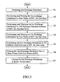
- FIG. 3 shows the ion exchange membrane rinsing process.
- An ion exchange membrane is prepared first (step 101).
- a suitable example for the ion exchange membrane is Nafion® of Du Pont Corporation.
- a preferred example of the ion exchange membrane is Nafion 117 having a thickness of 175 ⁇ m, which is considered thick enough to block transmission/penetration of alcohol, serving as a solvent of the catalyst solutions, therethrough during the manufacturing process, which causes toxication to platinum that is commonly used as anode catalyst in the fuel cell. Effectively blocking the transmission/penetration of the alcohol through the ion exchange membrane to get into contact with the anode catalyst maintains the performance of the fuel cell.
- the rinsing process comprises positioning and rinsing the ion exchange membrane in pure water of 80°C for one hour (step 102), positioning and washing the ion exchange membrane in 1M hydrogen peroxide solution of 80°C for another hour (step 103), positioning and rinsing the ion exchange membrane again in pure water of 80°C for one hour (step 104), positioning the ion exchange membrane in 1M sulfuric acid solution of 80°C for one hour (step 105) and completely rinsing the ion exchange membrane two or three times with pure water 80°C (step 106).
- the so cleaned ion exchange membrane is then dried in room temperature (step 107).
- FIG. 4 illustrates the process of preparing catalyst solutions.
- step 201 raw materials for making the catalyst solutions are prepared.
- the catalyst solutions are made of Nafion solution Se-5112 obtained from Du Pont Corporation and Pt-Ru-C obtained from Johnson Matthey Co. for anode catalyst and Pt-C for cathode catalyst.
- the anode catalyst includes Pt-C
- the cathode catalyst also includes Pt-C.
- step 202 one gram of nano-sized catalyst powders at a ratio of 2:1:2 for Pt-Ru-C is put into a flask and added with 4-8 ml Nafion solution, which is then subject to ultrasonic vibration and/or high speed stirring to form a uniform mixture, serving as anode catalyst solution, step 203.
- step 204 one gram of nano-sized catalyst powders at a ratio of 1:1 for Pt-C is put into a flask and added with 4-8 ml Nafion solution, which is then subject to ultrasonic vibration and/or high speed stirring to form a uniform mixture, serving as anode catalyst solution, step 205.
- the ion exchange membrane that is trimmed to a suitable size is properly cleaned.
- the ion exchange membrane is positioned on a thin base plate made of stainless steel (step 301) and the base plate with the ion exchange membrane thereon is positioned on a screen-printing platform.
- the ion exchange membrane is trimmed to a size of 7cm x 7cm and is positioned on a base plate made of stainless steel having a surface area of 8cm x 8 cm and a thickness of 0.2mm.
- a steel screen plate of 0.05-0.3mm pitch and 30-160 mesh or a steel plate having a predetermined width and gap is employed as a printing plate for performing printing operation.
- the printing plate is fixed to a screen retainer on the printing platform, step 302.
- the anode catalyst solution is uniformly coated on a patterned area of 5cm ⁇ 5cm in the printing plate by a scraper, step 303.
- the anode catalyst solution is then transferred and printed onto the ion exchange membrane positioned on the base plate by the scraper, step 304.
- the ion exchange membrane Upon printing of the anode catalyst solution is performed, the ion exchange membrane absorbs solvent that comprises the anode catalyst solution and gets swelled.
- the ion exchange membrane is positioned on a heating board after the printing operation, step 305.
- the ion exchange membrane and the anode catalyst solution are heated to about 70-80°C for 1-5 minutes.
- the heat that is applied to the ion exchange membrane facilitates evaporation of the solvent from the ion exchange membrane, thereby removing the solvent out of the ion exchange membrane.
- the heat also facilitates to cure the catalyst solution. In practice, only minor swelling of the ion exchange membrane occurs during the heating process and soon the ion exchange membrane gets straightened and flattened. No cracking of the catalyst layer is observed on the heat-treated ion exchange membrane.
- An anode catalyst layer is thus formed on one surface (anode side) of the ion exchange membrane once the ion exchange membrane gets straightened and flattened.
- a similar process is employed on the cathode side of the ion exchange membrane, step 306, which repeats steps 301-304, but with the anode catalyst replaced by cathode catalyst, to form the cathode catalyst layer.
- the ion exchange membrane is positioned on a heating board (step 307), and the ion exchange membrane and the cathode catalyst solution are heated to about 70-80°C for 1-5 minutes. This forms the cathode catalyst coating on the ion exchange membrane.
- the ion exchange membrane is fed into a hot pressing machine for hot pressing, step 308, in which the ion exchange membrane is subject to a pressure of about 1 ⁇ 96-9 ⁇ 8 MPa (20-100kgf/cm 2 ) at a temperature of about 110-140°C for 1-3 minutes.
- the anode catalyst layer is formed first by means of printing and heating, yet it is possible to form the cathode catalyst layer before the anode catalyst layer or alternatively, the anode and cathode layers can be printed and heated at the same time. In other words, the sequence of the formation of the anode and cathode catalyst layers is of no concern in the present invention.
Landscapes
- Engineering & Computer Science (AREA)
- Chemical & Material Sciences (AREA)
- Manufacturing & Machinery (AREA)
- General Chemical & Material Sciences (AREA)
- Chemical Kinetics & Catalysis (AREA)
- Electrochemistry (AREA)
- Life Sciences & Earth Sciences (AREA)
- Sustainable Development (AREA)
- Sustainable Energy (AREA)
- Physics & Mathematics (AREA)
- Thermal Sciences (AREA)
- Materials Engineering (AREA)
- Fuel Cell (AREA)
- Inert Electrodes (AREA)
Claims (10)
- Methode zur Herstellung eines Membranelektrodenzusammenbaus einer Brennstoffzelle, die sich aus nachfolgenden Schritten zusammensetzt:(a) Herstellung einer Ionenaustauschmembran von vorgegebener Größe und Ansatz einer Anoden-Katalysatorlösung und einer Kathoden-Katalysatorlösung, wobei die Ionenaustauschmembran eine erste und eine zweite Flächenseite aufweist und der Schritt der Herstellung der Ionenaustauschmembran folgende Schritte umfasst:(i) Spülen der Ionenaustauschmembran in reinem Wasser bei 80°C über eine Stunde;(ii) Waschen der Ionenaustauschmembran in 1 M Wasserstoffsuperoxidlösung bei 80°C über eine Stunde;(iii) Spülen der Ionenaustauschmembran in reinem Wasser bei 80°C über eine Stunde;(iv) Waschen der Ionenaustauschmembran in 1 M Schwefelsäurelösung bei 80°; und(v) Zwei- oder dreimaliges Spülen der Ionenaustauschmembran mit reinem Wasser bei 80°C;(b) Platzieren der Ionenaustauschmembran von vorgegebener Größe auf einer Tragplatte, die anschließend auf einer Siebdruckplattform montiert wird.(c) Montage einer Druckplatte in einem Siebrahmen auf der Plattform;(d) Auftragen der Anoden- oder Kathoden-Katalysatorlösung auf einen gemusterten Bereich der Druckplatte mit einem Abstreifer und Aufdrucken der Katalysatorlösung auf die erste Flächenseite der Ionenaustauschmembran auf der Tragplatte mit dem Abstreifer;(e) Platzieren der Ionenaustauschmembran auf einer Heizplatte zum Erwärmen sowohl der Ionenaustauschmembran und der auf die erste Flächenseite der Ionenaustauschmembran aufgedruckten Katalysatorlösung;(f) Aushärten der Katalysatorlösung und warten, bis sich die Ionenaustauschmembran verflacht und dabei einheitliche Katalysatorlagen auf der Ionenaustauschmembran bildet;(g) Auftragen der anderen der Anoden- oder Kathoden-Katalysatorlösung auf einen gemusterten Bereich der Druckplatte mit einem Abstreifer und Aufdrucken der Katalysatorlösung auf die zweite Flächenseite der Ionenaustauschmembran auf der Tragplatte mit dem Abstreifer;(h) Platzieren der Ionenaustauschmembran auf der Heizplatte zum Erwärmen sowohl der Ionenaustauschmembran und der auf die zweite Flächenseite der Ionenaustauschmembran aufgedruckten Katalysatorlösung;(i) Warmpressen der Ionenaustauschmembran.
- Methode gemäß Anspruch 1, bei der die erste Fläche eine Anodenfläche der Ionenaustauschmembran und die zweite Fläche eine Kathodenfläche der Ionenaustauschmembran ist.
- Methode gemäß Anspruch 1, bei der die erste Fläche eine Kathodenfläche der Ionenaustauschmembran und die zweite Fläche eine Anodenfläche der Ionenaustauschmembran ist.
- Methode gemäß Anspruch 1, bei der die erste Katalysatorlösung eine Pt-R-C enthaltende Anoden-Katalysatorlösung und die zweite Katalysatorlösung eine Pt-C enthaltende Kathoden-Katalysatorlösung ist.
- Methode gemäß Anspruch 4, bei der der Ansatz der Anodenkatalysatorlösung folgende Schritte umfasst:(i) Platzierung von einem Gramm Pt-Ru-C im Verhältnis von 2:1:2 enthaltenden Nanoteilchen-Katalysatorpulvern in einem Kolben;(ii) Zusatz von 4-8 ml Nafionlösung zum Kolben, und(iii) Induktion mit Ultraschallschwingungen zur Herstellung einer einheitlichen Mischung aus dem Pulver und der Lösung.
- Methode gemäß Anspruch 4, bei der Ansatz der Kathodenkatalysatorlösung folgende Schritte umfasst:(i) Platzierung von einem Gramm Pt-C im Verhältnis von 1:1 enthaltenden Nanoteilchchen-Katalysatorpulvern in einem Kolben;(ii) Zusatz von 4-8 ml Nafionlösung zum Kolben, und(iii) Induktion mit Ultraschallschwingungen zur Herstellung einer einheitlichen Mischung aus dem Pulver und der Lösung.
- Methode gemäß Anspruch 1, bei der die Ionenaustauschmembran während der Schritte (e) und (h) von der Heizplatte 1-5 Minuten lang auf eine Temperatur von 70° bis 80°C erwärmt wird.
- Methode gemäß Anspruch 1, bei der das Warmpressen im Schritt (i) durch Beaufschlagung der Ionenaustauschmembran mit einem Druck von 1,96 Mpa bis 9,8 Mpa (20-100 kp/cm2) bei 110°C bis 140°C über einen Zeitraum von 1-3 Minuten erfolgt.
- Methode gemäß Anspruch 1, bei der die Druckplatte ein Sieb mit vorgegebenem Siebraster und vorgegbener Maschenweite aufweist.
- Methode gemäß Anspruch 1, bei der die Druckplatte eine Stahlplatte von vorgegebener Breite mit und Aussparungen aufweist.
Priority Applications (3)
| Application Number | Priority Date | Filing Date | Title |
|---|---|---|---|
| EP04253080A EP1601039B8 (de) | 2004-05-25 | 2004-05-25 | Verfahren zur Herstellung einer Membran-Elektrodenanordnung einer Brennstoffzelle durch ein Druckverfahren |
| DE602004025208T DE602004025208D1 (de) | 2004-05-25 | 2004-05-25 | Verfahren zur Herstellung einer Membran-Elektrodenanordnung einer Brennstoffzelle durch ein Druckverfahren |
| AT04253080T ATE456163T1 (de) | 2004-05-25 | 2004-05-25 | Verfahren zur herstellung einer membran- elektrodenanordnung einer brennstoffzelle durch ein druckverfahren |
Applications Claiming Priority (1)
| Application Number | Priority Date | Filing Date | Title |
|---|---|---|---|
| EP04253080A EP1601039B8 (de) | 2004-05-25 | 2004-05-25 | Verfahren zur Herstellung einer Membran-Elektrodenanordnung einer Brennstoffzelle durch ein Druckverfahren |
Publications (3)
| Publication Number | Publication Date |
|---|---|
| EP1601039A1 EP1601039A1 (de) | 2005-11-30 |
| EP1601039B1 true EP1601039B1 (de) | 2010-01-20 |
| EP1601039B8 EP1601039B8 (de) | 2010-03-10 |
Family
ID=34930338
Family Applications (1)
| Application Number | Title | Priority Date | Filing Date |
|---|---|---|---|
| EP04253080A Expired - Lifetime EP1601039B8 (de) | 2004-05-25 | 2004-05-25 | Verfahren zur Herstellung einer Membran-Elektrodenanordnung einer Brennstoffzelle durch ein Druckverfahren |
Country Status (3)
| Country | Link |
|---|---|
| EP (1) | EP1601039B8 (de) |
| AT (1) | ATE456163T1 (de) |
| DE (1) | DE602004025208D1 (de) |
Families Citing this family (1)
| Publication number | Priority date | Publication date | Assignee | Title |
|---|---|---|---|---|
| WO2009106620A1 (de) * | 2008-02-29 | 2009-09-03 | Basf Se | 5- oder 7-lagige membranelektrodeneinheit (mea) und deren herstellung durch heisspressen in gegenwart von lösungsmitteldampf |
Family Cites Families (3)
| Publication number | Priority date | Publication date | Assignee | Title |
|---|---|---|---|---|
| US5330860A (en) * | 1993-04-26 | 1994-07-19 | E. I. Du Pont De Nemours And Company | Membrane and electrode structure |
| US6589682B1 (en) * | 2000-01-27 | 2003-07-08 | Karen Fleckner | Fuel cells incorporating nanotubes in fuel feed |
| DE10159476A1 (de) * | 2001-12-04 | 2003-07-17 | Omg Ag & Co Kg | Verfahren zur Herstellung von Membran-Elektrodeneinheiten für Brennstoffzellen |
-
2004
- 2004-05-25 AT AT04253080T patent/ATE456163T1/de not_active IP Right Cessation
- 2004-05-25 DE DE602004025208T patent/DE602004025208D1/de not_active Expired - Fee Related
- 2004-05-25 EP EP04253080A patent/EP1601039B8/de not_active Expired - Lifetime
Also Published As
| Publication number | Publication date |
|---|---|
| EP1601039A1 (de) | 2005-11-30 |
| DE602004025208D1 (de) | 2010-03-11 |
| ATE456163T1 (de) | 2010-02-15 |
| EP1601039B8 (de) | 2010-03-10 |
Similar Documents
| Publication | Publication Date | Title |
|---|---|---|
| CN101887975B (zh) | 一种燃料电池用膜-膜电极的集成化制备方法 | |
| KR100409042B1 (ko) | 막전극 접합체와 그 제조 방법 | |
| US7758921B2 (en) | Method of fabricating electrode catalyst layers with directionally oriented carbon support for proton exchange membrane fuel cell | |
| CN1864290B (zh) | 制备膜电极组件的方法 | |
| JPWO2001022514A1 (ja) | 高分子電解質型燃料電池およびその製造方法 | |
| WO2001022514A1 (en) | Polymer electrolytic fuel cell and method for producing the same | |
| JP5017776B2 (ja) | 固体高分子形燃料電池用膜・触媒層接合体の製造方法、固体高分子形燃料電池の製造方法、及び固体高分子形燃料電池用膜・触媒層接合体の製造装置 | |
| CN115360396A (zh) | 一种燃料电池三维结构膜电极的制备方法 | |
| CN101645508A (zh) | 一种质子交换膜燃料电池用膜电极 | |
| CN107146891B (zh) | 一种贵金属催化剂颗粒呈梯度分布的mea制备方法 | |
| US7041191B2 (en) | Method for manufacturing membrane electrode assembly of fuel cell by printing processes | |
| WO2007089860A2 (en) | Method of making membrane electrode assemblies | |
| CN113366676A (zh) | 生产燃料电池的膜电极组件的方法 | |
| EP1601039B1 (de) | Verfahren zur Herstellung einer Membran-Elektrodenanordnung einer Brennstoffzelle durch ein Druckverfahren | |
| US20070248846A1 (en) | Method for Producing Membrane-Electrode Units | |
| Squadrito | Preparation of MEA | |
| CN114824299B (zh) | 一种ccm膜电极及其制备方法、应用 | |
| JP5838688B2 (ja) | 膜電極接合体の製造方法 | |
| JP2011090937A (ja) | 燃料電池用セパレータおよびその製造方法 | |
| EP1984967B1 (de) | Verfahren zur herstellung von membranelektrodenanordnungen für elektrochemische vorrichtungen | |
| JP2009245869A (ja) | 燃料電池用ガス拡散基材の製造方法 | |
| JP3898707B2 (ja) | 印刷工程で製造する燃料電池膜電極アセンブリの製造方法 | |
| CN201629376U (zh) | 一种质子交换膜燃料电池用膜电极 | |
| KR100705553B1 (ko) | 연료전지용 막전극접합체의 수소이온교환막 상에 촉매층을형성시키는 방법 | |
| JP2004259509A (ja) | 燃料電池電極の触媒層形成方法および電極製造方法 |
Legal Events
| Date | Code | Title | Description |
|---|---|---|---|
| PUAI | Public reference made under article 153(3) epc to a published international application that has entered the european phase |
Free format text: ORIGINAL CODE: 0009012 |
|
| 17P | Request for examination filed |
Effective date: 20040612 |
|
| AK | Designated contracting states |
Kind code of ref document: A1 Designated state(s): AT BE BG CH CY CZ DE DK EE ES FI FR GB GR HU IE IT LI LU MC NL PL PT RO SE SI SK TR |
|
| AX | Request for extension of the european patent |
Extension state: AL HR LT LV MK |
|
| AKX | Designation fees paid |
Designated state(s): AT BE BG CH CY CZ DE DK EE ES FI FR GB GR HU IE IT LI LU MC NL PL PT RO SE SI SK TR |
|
| 17Q | First examination report despatched |
Effective date: 20060202 |
|
| GRAP | Despatch of communication of intention to grant a patent |
Free format text: ORIGINAL CODE: EPIDOSNIGR1 |
|
| GRAS | Grant fee paid |
Free format text: ORIGINAL CODE: EPIDOSNIGR3 |
|
| GRAA | (expected) grant |
Free format text: ORIGINAL CODE: 0009210 |
|
| AK | Designated contracting states |
Kind code of ref document: B1 Designated state(s): AT BE BG CH CY CZ DE DK EE ES FI FR GB GR HU IE IT LI LU MC NL PL PT RO SE SI SK TR |
|
| REG | Reference to a national code |
Ref country code: GB Ref legal event code: FG4D |
|
| REG | Reference to a national code |
Ref country code: CH Ref legal event code: EP |
|
| REG | Reference to a national code |
Ref country code: IE Ref legal event code: FG4D |
|
| REF | Corresponds to: |
Ref document number: 602004025208 Country of ref document: DE Date of ref document: 20100311 Kind code of ref document: P |
|
| REG | Reference to a national code |
Ref country code: NL Ref legal event code: VDEP Effective date: 20100120 |
|
| PG25 | Lapsed in a contracting state [announced via postgrant information from national office to epo] |
Ref country code: AT Free format text: LAPSE BECAUSE OF FAILURE TO SUBMIT A TRANSLATION OF THE DESCRIPTION OR TO PAY THE FEE WITHIN THE PRESCRIBED TIME-LIMIT Effective date: 20100120 |
|
| PG25 | Lapsed in a contracting state [announced via postgrant information from national office to epo] |
Ref country code: PT Free format text: LAPSE BECAUSE OF FAILURE TO SUBMIT A TRANSLATION OF THE DESCRIPTION OR TO PAY THE FEE WITHIN THE PRESCRIBED TIME-LIMIT Effective date: 20100520 Ref country code: ES Free format text: LAPSE BECAUSE OF FAILURE TO SUBMIT A TRANSLATION OF THE DESCRIPTION OR TO PAY THE FEE WITHIN THE PRESCRIBED TIME-LIMIT Effective date: 20100501 Ref country code: NL Free format text: LAPSE BECAUSE OF FAILURE TO SUBMIT A TRANSLATION OF THE DESCRIPTION OR TO PAY THE FEE WITHIN THE PRESCRIBED TIME-LIMIT Effective date: 20100120 |
|
| PG25 | Lapsed in a contracting state [announced via postgrant information from national office to epo] |
Ref country code: SI Free format text: LAPSE BECAUSE OF FAILURE TO SUBMIT A TRANSLATION OF THE DESCRIPTION OR TO PAY THE FEE WITHIN THE PRESCRIBED TIME-LIMIT Effective date: 20100120 Ref country code: PL Free format text: LAPSE BECAUSE OF FAILURE TO SUBMIT A TRANSLATION OF THE DESCRIPTION OR TO PAY THE FEE WITHIN THE PRESCRIBED TIME-LIMIT Effective date: 20100120 Ref country code: FI Free format text: LAPSE BECAUSE OF FAILURE TO SUBMIT A TRANSLATION OF THE DESCRIPTION OR TO PAY THE FEE WITHIN THE PRESCRIBED TIME-LIMIT Effective date: 20100120 |
|
| PG25 | Lapsed in a contracting state [announced via postgrant information from national office to epo] |
Ref country code: RO Free format text: LAPSE BECAUSE OF FAILURE TO SUBMIT A TRANSLATION OF THE DESCRIPTION OR TO PAY THE FEE WITHIN THE PRESCRIBED TIME-LIMIT Effective date: 20100120 Ref country code: SE Free format text: LAPSE BECAUSE OF FAILURE TO SUBMIT A TRANSLATION OF THE DESCRIPTION OR TO PAY THE FEE WITHIN THE PRESCRIBED TIME-LIMIT Effective date: 20100120 Ref country code: GR Free format text: LAPSE BECAUSE OF FAILURE TO SUBMIT A TRANSLATION OF THE DESCRIPTION OR TO PAY THE FEE WITHIN THE PRESCRIBED TIME-LIMIT Effective date: 20100421 Ref country code: EE Free format text: LAPSE BECAUSE OF FAILURE TO SUBMIT A TRANSLATION OF THE DESCRIPTION OR TO PAY THE FEE WITHIN THE PRESCRIBED TIME-LIMIT Effective date: 20100120 Ref country code: CY Free format text: LAPSE BECAUSE OF FAILURE TO SUBMIT A TRANSLATION OF THE DESCRIPTION OR TO PAY THE FEE WITHIN THE PRESCRIBED TIME-LIMIT Effective date: 20100120 Ref country code: BE Free format text: LAPSE BECAUSE OF FAILURE TO SUBMIT A TRANSLATION OF THE DESCRIPTION OR TO PAY THE FEE WITHIN THE PRESCRIBED TIME-LIMIT Effective date: 20100120 |
|
| PLBE | No opposition filed within time limit |
Free format text: ORIGINAL CODE: 0009261 |
|
| STAA | Information on the status of an ep patent application or granted ep patent |
Free format text: STATUS: NO OPPOSITION FILED WITHIN TIME LIMIT |
|
| PG25 | Lapsed in a contracting state [announced via postgrant information from national office to epo] |
Ref country code: BG Free format text: LAPSE BECAUSE OF FAILURE TO SUBMIT A TRANSLATION OF THE DESCRIPTION OR TO PAY THE FEE WITHIN THE PRESCRIBED TIME-LIMIT Effective date: 20100420 Ref country code: SK Free format text: LAPSE BECAUSE OF FAILURE TO SUBMIT A TRANSLATION OF THE DESCRIPTION OR TO PAY THE FEE WITHIN THE PRESCRIBED TIME-LIMIT Effective date: 20100120 Ref country code: CZ Free format text: LAPSE BECAUSE OF FAILURE TO SUBMIT A TRANSLATION OF THE DESCRIPTION OR TO PAY THE FEE WITHIN THE PRESCRIBED TIME-LIMIT Effective date: 20100120 |
|
| 26N | No opposition filed |
Effective date: 20101021 |
|
| PG25 | Lapsed in a contracting state [announced via postgrant information from national office to epo] |
Ref country code: MC Free format text: LAPSE BECAUSE OF NON-PAYMENT OF DUE FEES Effective date: 20100531 |
|
| REG | Reference to a national code |
Ref country code: CH Ref legal event code: PL |
|
| PG25 | Lapsed in a contracting state [announced via postgrant information from national office to epo] |
Ref country code: DK Free format text: LAPSE BECAUSE OF FAILURE TO SUBMIT A TRANSLATION OF THE DESCRIPTION OR TO PAY THE FEE WITHIN THE PRESCRIBED TIME-LIMIT Effective date: 20100120 |
|
| REG | Reference to a national code |
Ref country code: FR Ref legal event code: ST Effective date: 20110131 |
|
| PG25 | Lapsed in a contracting state [announced via postgrant information from national office to epo] |
Ref country code: CH Free format text: LAPSE BECAUSE OF NON-PAYMENT OF DUE FEES Effective date: 20100531 Ref country code: LI Free format text: LAPSE BECAUSE OF NON-PAYMENT OF DUE FEES Effective date: 20100531 |
|
| PG25 | Lapsed in a contracting state [announced via postgrant information from national office to epo] |
Ref country code: IT Free format text: LAPSE BECAUSE OF FAILURE TO SUBMIT A TRANSLATION OF THE DESCRIPTION OR TO PAY THE FEE WITHIN THE PRESCRIBED TIME-LIMIT Effective date: 20100120 |
|
| PG25 | Lapsed in a contracting state [announced via postgrant information from national office to epo] |
Ref country code: DE Free format text: LAPSE BECAUSE OF NON-PAYMENT OF DUE FEES Effective date: 20101201 Ref country code: IE Free format text: LAPSE BECAUSE OF NON-PAYMENT OF DUE FEES Effective date: 20100525 |
|
| PG25 | Lapsed in a contracting state [announced via postgrant information from national office to epo] |
Ref country code: FR Free format text: LAPSE BECAUSE OF NON-PAYMENT OF DUE FEES Effective date: 20100531 |
|
| PGFP | Annual fee paid to national office [announced via postgrant information from national office to epo] |
Ref country code: GB Payment date: 20110406 Year of fee payment: 8 |
|
| PG25 | Lapsed in a contracting state [announced via postgrant information from national office to epo] |
Ref country code: LU Free format text: LAPSE BECAUSE OF NON-PAYMENT OF DUE FEES Effective date: 20100525 Ref country code: HU Free format text: LAPSE BECAUSE OF FAILURE TO SUBMIT A TRANSLATION OF THE DESCRIPTION OR TO PAY THE FEE WITHIN THE PRESCRIBED TIME-LIMIT Effective date: 20100721 |
|
| PG25 | Lapsed in a contracting state [announced via postgrant information from national office to epo] |
Ref country code: TR Free format text: LAPSE BECAUSE OF FAILURE TO SUBMIT A TRANSLATION OF THE DESCRIPTION OR TO PAY THE FEE WITHIN THE PRESCRIBED TIME-LIMIT Effective date: 20100120 |
|
| GBPC | Gb: european patent ceased through non-payment of renewal fee |
Effective date: 20120525 |
|
| PG25 | Lapsed in a contracting state [announced via postgrant information from national office to epo] |
Ref country code: GB Free format text: LAPSE BECAUSE OF NON-PAYMENT OF DUE FEES Effective date: 20120525 |