EP1600748A1 - Radar-Füllstandsmessgerät - Google Patents
Radar-Füllstandsmessgerät Download PDFInfo
- Publication number
- EP1600748A1 EP1600748A1 EP05003958A EP05003958A EP1600748A1 EP 1600748 A1 EP1600748 A1 EP 1600748A1 EP 05003958 A EP05003958 A EP 05003958A EP 05003958 A EP05003958 A EP 05003958A EP 1600748 A1 EP1600748 A1 EP 1600748A1
- Authority
- EP
- European Patent Office
- Prior art keywords
- radar
- section
- grounding
- predetermined wavelength
- antenna
- Prior art date
- Legal status (The legal status is an assumption and is not a legal conclusion. Google has not performed a legal analysis and makes no representation as to the accuracy of the status listed.)
- Granted
Links
Images
Classifications
-
- G—PHYSICS
- G01—MEASURING; TESTING
- G01F—MEASURING VOLUME, VOLUME FLOW, MASS FLOW OR LIQUID LEVEL; METERING BY VOLUME
- G01F23/00—Indicating or measuring liquid level or level of fluent solid material, e.g. indicating in terms of volume or indicating by means of an alarm
- G01F23/22—Indicating or measuring liquid level or level of fluent solid material, e.g. indicating in terms of volume or indicating by means of an alarm by measuring physical variables, other than linear dimensions, pressure or weight, dependent on the level to be measured, e.g. by difference of heat transfer of steam or water
- G01F23/28—Indicating or measuring liquid level or level of fluent solid material, e.g. indicating in terms of volume or indicating by means of an alarm by measuring physical variables, other than linear dimensions, pressure or weight, dependent on the level to be measured, e.g. by difference of heat transfer of steam or water by measuring the variations of parameters of electromagnetic or acoustic waves applied directly to the liquid or fluent solid material
- G01F23/284—Electromagnetic waves
Definitions
- the invention relates to a radar level measuring device, with a high-frequency device for generating and processing radar signals with predetermined Frequency and wavelength, an antenna for blasting and / or Receiving the radar signals and one provided on a board and a microstrip line circuit for connecting the high frequency device with the antenna, wherein the microstrip line is a grounding line having.
- a radar level measuring device is z. B. off of US 2004/0066588 A1.
- level measuring method differs.
- a medium such as a liquid or a bulk material in a container, such as a tank measure up.
- level measuring method differs.
- the level measurement in which a part of the measuring device with the Medium whose level is to be measured, comes into contact, z. B. the level measurement by means of a float, a buoyancy body or a touch plate.
- the contacting level measuring methods are included Capacitive measurements in which the filling level dependent capacity between an immersed in the medium electrode and the wall of the container detected is, as well as a thermal measurement, in which the increased heat dissipation when immersing a current-carrying, temperature-dependent resistor in the medium is exploited by the fact that the electrical resistance changed with the immersion depth.
- the non-contacting level measurement include z. B. the measurement by laser or ultrasound. This is a laser or ultrasonic signal emitted, reflected on the surface of the medium, and that reflected Signal is detected again, with the level of the medium over the Running time of the signal is closed.
- This is based on the same principle Radar Gremansmeßclar in which generates a microwave signal over an antenna, such as a rod antenna or a horn antenna, towards the medium whose level is to be measured is emitted at the Surface of the medium is reflected and from the antenna or another Antenna is detected again.
- TDR Time Domaine Reflectometry
- conductor-bound transmission links are required, like a coaxial line, which consists of an inner conductor and an outer conductor intervening dielectric, or a parallel line, in which two conductors through spacers or a dielectric sheath parallel be guided.
- waveguides are known which consist of a metallic Tube of round or rectangular cross-section consist in which can propagate the high-frequency electromagnetic radar signal.
- the interior of the waveguide may be filled with air or with a dielectric be.
- planar marsheren consist of even pipeline structures exist, which are applied to a dielectric substrate.
- Such planar pipes can z. B. in the form of microstrip lines on a circuit board be applied, wherein on one side of the board the actual Waveguide structures and on the other side of the board one of these Waveguide structures through the existing of dielectric material board
- planar piping such as Microstrip lines, have the advantage that other components to simple Way planar mounted and can be provided on the board.
- a radar level gauge as well as others Measuring equipment to perform explosion-proof.
- For radar level gauges if such explosion protection is required in particular if z. B. determines the level of an explosive medium in a tank shall be.
- DIN EN 50014 are provisions for electrical equipment specified in potentially explosive atmospheres, namely in the form of different types of protection.
- Such an intrinsically safe circuit includes besides interconnections at least one intrinsically safe resource and one associated equipment.
- An intrinsically safe equipment is a resource referred to, which has only intrinsically safe circuits That is, the voltage and current in the intrinsically safe resource always so small, so that in case of short circuit, interruption or ground fault the ignition energy always remains smaller than the minimum ignition energy, so that no Ignition of an explosive gas mixture can take place.
- Intrinsically safe equipment are suitable for operation directly in potentially explosive atmospheres
- associated resources are such resources where not all circuits are intrinsically safe are.
- an associated resource contains at least one intrinsically safe one Circuit, which are led into the explosion-endangered area may.
- a non-intrinsically safe signal is converted into an intrinsically safe signal.
- Associated resources are z. As a pure signal separator, typically referred to as safety barriers, or signal transforming Devices in front, z. B. in the form of transducers, Transmitterspeiseijnn or Isolation amplifiers.
- this grounding line in particular, if sufficient Wide and safe grounding, intrinsic safety of the circuit can be achieved since they are for low-frequency signal components or DC components as ground acts while the high-frequency signal components are not affected, this Do not "see” the type of grounding.
- the grounding a first section, a fan and a second section has, the length of the first portion substantially a quarter of predetermined wavelength of the radar signals, at the end of the first Section of the compartments is provided at the end of the first section and the fan connects the second section and the second section is grounded is.
- Essential to the invention is therefore that the first section of the grounding line not directly on earth, but has a fan at its end.
- fan called in English "radial stub", such Planar line structure referred to, which is essentially the shape of a quarter circle and may be part of a microstrip line.
- the mode of action such a fan is practically that of a filter, and indeed in the form of a blocking capacity for high frequencies. It means that by providing the fan at the end of the first section of the grounding line a "virtual ground” for high frequencies is present, so that behind the fan practically only DC shares exist, which then on conventional Way, z. B. through a via to one on the other Side of the board grounding layer are grounded.
- the fan with its tip the end of the first section and touched the beginning of the second section is in particular provided that the fan with its tip the end of the first section and touched the beginning of the second section. Furthermore, according to a preferred embodiment of the invention provided that the radius of the fan substantially equal to a quarter of the predetermined wavelength or slightly less than a quarter of the predetermined wavelength is.
- the length of the first section of the grounding line is substantially one fourth of the predetermined wavelength of the radar signals is intended
- the length of the second section of the grounding line is less critical. According to a preferred embodiment of the invention, however, it is provided that the length of the second section is less than half of the predetermined Wavelength. Furthermore, it is preferred that the length of the second Section essentially between one-eighth and three-eighths of the predetermined Wavelength is. It is also very particularly preferred here the length of the second section is substantially one quarter of the predetermined one Wavelength corresponds.
- grounding lines with have such a large width only a small frequency bandwidth which is of course disadvantageous to the operation of the radar level gauge.
- the grounding leads can then be much narrower than in the case in which a ground line alone has to ensure intrinsic safety, whereby the achievable frequency bandwidth is significantly improved.
- the grounding leads together are dimensioned so that a sufficient grounding effect for the type of protection "intrinsic safety”.
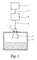
- Fig. 1 Radar Mediresmeß réelle has a high-frequency device 1 for generating and processing radar signals with a predetermined one Frequency of typically several GHz, what wavelengths of a few cm.
- antenna 2 for emitting and receiving of radar signals is provided a horn antenna. Basically also a rod antenna can be provided.
- the antenna 2 is connected via a flange or Einschraub 3 in one Container 4 is arranged, in which a medium 5 hailr whose fill level to be determined.
- a circuit board 6 Between the high-frequency device 1 and the Antenna 2 is a circuit board 6, which is connected to a supply line 7 to the high-frequency device 1 and connected to a supply line 8 to the antenna 2. Details of the possible design of the board 6 are Figs. 2 and 3 can be removed.
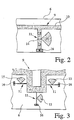
- Fig. 2 shows a detail of the embodiment of the board 6 according to a first preferred embodiment of the invention.
- the circuit board 6 is provided with a microstrip line 9 on one side, on the one hand with the supply line 7 to Hochfrequez Rhein 1 with the supply line 8 to the antenna 2 connecting line portion 10 and a grounding line 11 has.
- the grounding line has a first portion 12 and a second section 13.
- a fan 15 is provided, which contacts the grounding line 11 with its tip.
- Dimensioning and function of grounding line 11 is now as follows:
- the first portion 12 has a length substantially exactly one Quarter of the predetermined wavelength of the radar signals corresponds. Which to the first section 12 directly adjacent second section 13 has according to the presently described first preferred embodiment The invention also has a length which is one quarter of the predetermined Wavelength of the radar signals corresponds.
- the length of the second section 13 is less critical than the length of the first section 12, so that z. B, also a length of the second section 13 of one-eighth or three Be provided eighth of the predetermined wavelength of the radar signals could.
- the second section 13 is facing away from the first section 12 at its End grounded, namely the fact that he by means of a via 16 provided with a on the other side of the board 6, not connected earthing layer is further connected.
- the fan 15 acts there as a kind of blocking capacity for high frequencies, so that a "virtual short circuit" for high-frequency signal components is achieved.
- the main advantages of this construction lie in the fact that it is well reproducible and numerical Simulation method can be calculated well, since only one side of the board 6 im Simulation method must be considered.
- FIG. 3 is a detail of a circuit board 6 with microstrip line. 9 according to a second preferred embodiment of the invention can be seen. It is provided that a plurality of grounding lines 11, namely exactly three grounding lines 11, are provided to the type of protection To achieve "intrinsic safety". Unlike the grounding line 11 according to the first preferred embodiment of the invention are the Grounding lines 11 according to the presently described second preferred Embodiment of the invention designed much narrower, namely each have a significantly smaller width than 2 mm, which is present roughly representing the lower limit for having a single grounding line 11 to achieve intrinsic safety. This would be a single grounding line 11 according to the second preferred embodiment of the invention not suffice to provide sufficient grounding to achieve the intrinsic safety type of protection to reach. By the combination of three earthing cables 11 can be remedied this problem, however, as an advantage It should be noted that the frequency bandwidth due to the narrower grounding lines 11 compared to the construction according to the first preferred embodiment of the invention is significantly increased.
Abstract
Description
- Fig. 1
- schematisch ein Radar-Füllstandsmeßgerät gemäß einem bevorzugten Ausführungsbeispiel der Erfindung,
- Fig. 2
- schematisch den Aufbau der Mikrostreifenleitung mit einer Erdungsleitung gemäß einem ersten bevorzugten Ausführungsbeispiel der Erfindung und
- Fig. 3
- schematisch den Aufbau einer Mikrostreifenleitung mit drei Erdungsleitungen gemäß einem zweiten bevorzugten Ausführungsbeispiel der Erfindung.
Claims (9)
- Radar-Füllstandsmeßgerät, mit einer Hochfrequenzeinrichtung (1) zum Erzeugen und Verarbeiten von Radar-Signalen mit vorbestimmter Frequenz und Wellenlänge, einer Antenne (2) zum Abstrahlen oder/und Empfangen der Radar-Signale sowie einer auf einer Platine (6) vorgesehenen und eine Mikrostreifenleitung (9) aufweisenden Schaltung zum Verbinden der Hochfrequenzeinrichtung (1) mit der Antenne (2), wobei die Mikrostreifenleitung (9) eine Erdungsleitung (11) aufweist, dadurch gekennzeichnet, daß die Erdungsleitung (11) einen ersten Abschnitt (12), einen Fächer (15) und einen zweiten Abschnitt (13) aufweist, die Länge des ersten Abschnitts (11) im wesentlichen einem Viertel der vorbestimmten Wellenlänge entspricht, am Ende des ersten Abschnitts (12) der Fächer (15) vorgesehen ist, sich an das Ende das ersten Abschnitts (12) und den Fächer (15) der zweite Abschnitt (13) anschließt und der zweite Abschnitt (13) geerdet ist.
- Radar-Füllstandsmeßgerät nach Anspruch 1, dadurch gekennzeichnet, daß der Fächer (15) mit seiner Spitze das Ende des ersten Abschnitts (12) und den Anfang des zweiten Abschnitts (13) berührt.
- Radar-Füllstandsmeßgerät nach Anspruch 1 oder 2, dadurch gekennzeichnet, daß der Radius des Fächers (15) im wesentlichen einem Viertel der vorbestimmten Wellenlänge entspricht oder geringfügig geringer als ein Viertel der vorbestimmten Wellenlänge ist.
- Radar-Füllstandsmeßgerät nach einem der Ansprüche 1 bis 3, dadurch gekennzeichnet, daß die Länge des zweiten Abschnitts (13) geringer ist als die Hälfte der vorbestimmten Wellenlänge.
- , Radar-Füllstandsmeßgerät nach Anspruch 4, dadurch gekennzeichnet, daß die Länge des zweiten Abschnitts (13) im wesentlichen zwischen einem Achtel und drei Achteln der vorbestimmten Wellenlänge liegt.
- Radar-Füllstandsmeßgerät nach Anspruch 5, dadurch gekennzeichnet, daß die Länge des zweiten Abschnitts (13) im wesentlichen einem Viertel der vorbestimmten Wellenlänge entspricht.
- Radar-Füllstandsmeßgerät nach einem der Ansprüche 1 bis 6, dadurch gekennzeichnet, daß der zweite Abschnitt (13) mittels einer Durchkontaktierung (16) an eine auf der anderen Seite der Platine (6) vorgesehene Erdungsschicht angeschlossen ist.
- Radar-Füllstandsmeßgerät nach einem der Ansprüche-1 bis 7, dadurch gekennzeichnet, daß eine Mehrzahl von Erdungsleitungen (11) vorgesehen ist.
- Radar-Füllstandsmeßgerät nach einem Anspruch 8, dadurch gekennzeichnet, daß die Erdungsleitungen (11) derart dimensioniert sind, insbesondere eine derartige Breite aufweisen, daß nur durch Vorsehen aller Erdungsleitungen (11) Eigensicherheit erzielbar ist.
Applications Claiming Priority (2)
| Application Number | Priority Date | Filing Date | Title |
|---|---|---|---|
| DE102004026560 | 2004-05-26 | ||
| DE102004026560A DE102004026560B4 (de) | 2004-05-26 | 2004-05-26 | Radar-Füllstandsmeßgerät |
Publications (2)
| Publication Number | Publication Date |
|---|---|
| EP1600748A1 true EP1600748A1 (de) | 2005-11-30 |
| EP1600748B1 EP1600748B1 (de) | 2016-04-13 |
Family
ID=34933900
Family Applications (1)
| Application Number | Title | Priority Date | Filing Date |
|---|---|---|---|
| EP05003958.5A Not-in-force EP1600748B1 (de) | 2004-05-26 | 2005-02-24 | Radar-Füllstandsmessgerät |
Country Status (4)
| Country | Link |
|---|---|
| US (1) | US7227495B2 (de) |
| EP (1) | EP1600748B1 (de) |
| DE (1) | DE102004026560B4 (de) |
| DK (1) | DK1600748T3 (de) |
Families Citing this family (9)
| Publication number | Priority date | Publication date | Assignee | Title |
|---|---|---|---|---|
| DE102004026560B4 (de) * | 2004-05-26 | 2006-03-09 | Krohne S.A. | Radar-Füllstandsmeßgerät |
| US7355548B2 (en) * | 2005-09-01 | 2008-04-08 | Rosemount Tank Radar Ab | Processing of tank signal in radar level gauge system |
| US7498974B2 (en) * | 2006-09-21 | 2009-03-03 | Rosemount Tank Radar Ab | Radar level gauge with a galvanically isolated interface |
| US7701385B2 (en) * | 2008-05-22 | 2010-04-20 | Rosemount Tank Radar Ab | Multi-channel radar level gauge system |
| US8253641B1 (en) * | 2009-07-08 | 2012-08-28 | Northrop Grumman Systems Corporation | Wideband wide scan antenna matching structure using electrically floating plates |
| RU2471159C1 (ru) * | 2011-06-15 | 2012-12-27 | Закрытое акционерное общество "Лимако" | Радиолокационный уровнемер |
| KR101442475B1 (ko) * | 2012-03-08 | 2014-09-23 | 주식회사 한라홀딩스 | 레이더 장치 |
| US20160238427A1 (en) * | 2015-02-13 | 2016-08-18 | Honeywell International Inc. | Electronic level gauge having improved noise rejection and power transmission |
| DE102016217614B4 (de) * | 2016-09-15 | 2023-12-14 | Vega Grieshaber Kg | Antennenanordnung |
Citations (3)
| Publication number | Priority date | Publication date | Assignee | Title |
|---|---|---|---|---|
| WO1994028592A1 (en) * | 1993-05-27 | 1994-12-08 | E.I. Du Pont De Nemours And Company | High tc superconductor/ferroelectric tunable microwave circuits |
| EP1069679A1 (de) * | 1999-07-16 | 2001-01-17 | Thomson-Csf | Kostengünstiger Begrenzer für hohe Leistungen |
| US20040066588A1 (en) * | 2002-09-30 | 2004-04-08 | Magnetrol International | Process control instrument intrinsic safety barrier |
Family Cites Families (9)
| Publication number | Priority date | Publication date | Assignee | Title |
|---|---|---|---|---|
| US5511238A (en) * | 1987-06-26 | 1996-04-23 | Texas Instruments Incorporated | Monolithic microwave transmitter/receiver |
| US5109205A (en) * | 1990-11-08 | 1992-04-28 | Honeywell Inc. | Millimeter wave microstrip shunt-mounted pin diode switch with particular bias means |
| US5309163A (en) * | 1991-09-12 | 1994-05-03 | Trw Inc. | Active patch antenna transmitter |
| US5583523A (en) * | 1992-01-06 | 1996-12-10 | C & K Systems, Incorporation | Planar microwave tranceiver employing shared-ground-plane antenna |
| US6091355A (en) * | 1998-07-21 | 2000-07-18 | Speed Products, Inc. | Doppler radar speed measuring unit |
| US6246377B1 (en) * | 1998-11-02 | 2001-06-12 | Fantasma Networks, Inc. | Antenna comprising two separate wideband notch regions on one coplanar substrate |
| DE10240550A1 (de) * | 2002-08-29 | 2004-03-18 | Krohne S.A. | Füllstandsmeßgerät |
| DE10300955B4 (de) * | 2003-01-13 | 2005-10-27 | Epcos Ag | Radar-Transceiver für Mikrowellen- und Millimeterwellenanwendungen |
| DE102004026560B4 (de) * | 2004-05-26 | 2006-03-09 | Krohne S.A. | Radar-Füllstandsmeßgerät |
-
2004
- 2004-05-26 DE DE102004026560A patent/DE102004026560B4/de not_active Expired - Fee Related
-
2005
- 2005-02-24 EP EP05003958.5A patent/EP1600748B1/de not_active Not-in-force
- 2005-02-24 DK DK05003958.5T patent/DK1600748T3/en active
- 2005-04-19 US US11/109,532 patent/US7227495B2/en active Active
Patent Citations (3)
| Publication number | Priority date | Publication date | Assignee | Title |
|---|---|---|---|---|
| WO1994028592A1 (en) * | 1993-05-27 | 1994-12-08 | E.I. Du Pont De Nemours And Company | High tc superconductor/ferroelectric tunable microwave circuits |
| EP1069679A1 (de) * | 1999-07-16 | 2001-01-17 | Thomson-Csf | Kostengünstiger Begrenzer für hohe Leistungen |
| US20040066588A1 (en) * | 2002-09-30 | 2004-04-08 | Magnetrol International | Process control instrument intrinsic safety barrier |
Also Published As
| Publication number | Publication date |
|---|---|
| DE102004026560A1 (de) | 2005-12-22 |
| EP1600748B1 (de) | 2016-04-13 |
| US7227495B2 (en) | 2007-06-05 |
| DE102004026560B4 (de) | 2006-03-09 |
| US20050264442A1 (en) | 2005-12-01 |
| DK1600748T3 (en) | 2016-08-01 |
Similar Documents
| Publication | Publication Date | Title |
|---|---|---|
| EP1600748B1 (de) | Radar-Füllstandsmessgerät | |
| US5420517A (en) | Probe for measuring moisture in soil and other mediums | |
| EP2223060B1 (de) | VORRICHTUNG ZUR ERMITTLUNG UND/ODER ÜBERWACHUNG ZUMINDEST EINES FÜLLSTANDS VON ZUMINDEST EINEM MEDIUM IN EINEM BEHÄLTER GEMÄß EINER LAUFZEITMESSMETHODE UND/ODER EINER KAPAZITIVEN MESSMETHODE | |
| EP2340420B1 (de) | Füllstandsmessgerät | |
| EP1774616B1 (de) | Vorrichtung zur übertragung von breitbandigen hochfrequenzsignalen | |
| EP1285239B1 (de) | Füllstandsmessgerät | |
| DE60214755T2 (de) | Hornantenne für eine Pegelmesseinrichtung | |
| DE19958584C1 (de) | Füllstandmessgerät | |
| EP0821431B1 (de) | Anordnung zur Erzeugung und zum Senden von Mikrowellen, insb. für ein Füllstandsmessgerät | |
| EP1325289A1 (de) | Füllstandsmessgerät | |
| DE10027228A1 (de) | Vorrichtung zur Bestimmung und/oder Überwachung des Füllstandes eines Füllguts in einem Behälter | |
| EP1336119B1 (de) | Durchführung für ein elektrisches hochfrequenzsignal und füllstandmesseinrichtung mit einer solchen durchführung | |
| EP3791171A1 (de) | Tdr-messvorrichtung zur bestimmung der dielektrizitätskonstanten | |
| WO2013189707A1 (de) | Füllstandsmessgerät und vorrichtung zur bestimmung der dielektrizitätszahl | |
| DE4404745A1 (de) | Füllstandsmeßvorrichtung und deren Verwendung | |
| DE1591225B1 (de) | Generator zur erzeugung von entladungsstoessen hochfre quenter impulssignale mit hoher impulsfolgefrequenz | |
| DE112004001988T5 (de) | Verfahren und Vorrichtung zur Isolierung eines Radarfüllstandsmessgeräts | |
| DE602004006154T2 (de) | Sensor und gesamtvorrichtung zur hydrometrischen messung | |
| EP3473988B1 (de) | Füllstandmessanordnung mit schlauchartigen flexiblen sende- und empfangs-hohlleitern | |
| DE102018130260A1 (de) | Messgerät | |
| EP1186869A2 (de) | Füllstandsmessvorrichtung | |
| DE102013207604B4 (de) | Füllstandmessgerät | |
| DE102014112058B4 (de) | Wellenleiterübergangsvorrichtung und Verfahren zum Betreiben einer Wellenleiterübergangsvorrichtung | |
| DE102020131550A1 (de) | Kompaktes Radarmessgerät | |
| DE1573033C3 (de) | Einrichtung zur Messung des Pegelstandes von Substanzen |
Legal Events
| Date | Code | Title | Description |
|---|---|---|---|
| PUAI | Public reference made under article 153(3) epc to a published international application that has entered the european phase |
Free format text: ORIGINAL CODE: 0009012 |
|
| AK | Designated contracting states |
Kind code of ref document: A1 Designated state(s): AT BE BG CH CY CZ DE DK EE ES FI FR GB GR HU IE IS IT LI LT LU MC NL PL PT RO SE SI SK TR |
|
| AX | Request for extension of the european patent |
Extension state: AL BA HR LV MK YU |
|
| 17P | Request for examination filed |
Effective date: 20060126 |
|
| AKX | Designation fees paid |
Designated state(s): AT BE BG CH CY CZ DE DK EE ES FI FR GB GR HU IE IS IT LI LT LU MC NL PL PT RO SE SI SK TR |
|
| 17Q | First examination report despatched |
Effective date: 20120920 |
|
| GRAP | Despatch of communication of intention to grant a patent |
Free format text: ORIGINAL CODE: EPIDOSNIGR1 |
|
| INTG | Intention to grant announced |
Effective date: 20151022 |
|
| RIN1 | Information on inventor provided before grant (corrected) |
Inventor name: BLETZ, ACHIM Inventor name: MUSCH, THOMAS, DR. |
|
| GRAS | Grant fee paid |
Free format text: ORIGINAL CODE: EPIDOSNIGR3 |
|
| GRAA | (expected) grant |
Free format text: ORIGINAL CODE: 0009210 |
|
| AK | Designated contracting states |
Kind code of ref document: B1 Designated state(s): AT BE BG CH CY CZ DE DK EE ES FI FR GB GR HU IE IS IT LI LT LU MC NL PL PT RO SE SI SK TR |
|
| REG | Reference to a national code |
Ref country code: GB Ref legal event code: FG4D Free format text: NOT ENGLISH |
|
| REG | Reference to a national code |
Ref country code: AT Ref legal event code: REF Ref document number: 790629 Country of ref document: AT Kind code of ref document: T Effective date: 20160415 Ref country code: CH Ref legal event code: EP |
|
| REG | Reference to a national code |
Ref country code: IE Ref legal event code: FG4D Free format text: LANGUAGE OF EP DOCUMENT: GERMAN |
|
| REG | Reference to a national code |
Ref country code: DE Ref legal event code: R096 Ref document number: 502005015175 Country of ref document: DE |
|
| REG | Reference to a national code |
Ref country code: NL Ref legal event code: FP |
|
| REG | Reference to a national code |
Ref country code: DK Ref legal event code: T3 Effective date: 20160725 |
|
| REG | Reference to a national code |
Ref country code: LT Ref legal event code: MG4D |
|
| PG25 | Lapsed in a contracting state [announced via postgrant information from national office to epo] |
Ref country code: LT Free format text: LAPSE BECAUSE OF FAILURE TO SUBMIT A TRANSLATION OF THE DESCRIPTION OR TO PAY THE FEE WITHIN THE PRESCRIBED TIME-LIMIT Effective date: 20160413 Ref country code: FI Free format text: LAPSE BECAUSE OF FAILURE TO SUBMIT A TRANSLATION OF THE DESCRIPTION OR TO PAY THE FEE WITHIN THE PRESCRIBED TIME-LIMIT Effective date: 20160413 Ref country code: PL Free format text: LAPSE BECAUSE OF FAILURE TO SUBMIT A TRANSLATION OF THE DESCRIPTION OR TO PAY THE FEE WITHIN THE PRESCRIBED TIME-LIMIT Effective date: 20160413 |
|
| PG25 | Lapsed in a contracting state [announced via postgrant information from national office to epo] |
Ref country code: SE Free format text: LAPSE BECAUSE OF FAILURE TO SUBMIT A TRANSLATION OF THE DESCRIPTION OR TO PAY THE FEE WITHIN THE PRESCRIBED TIME-LIMIT Effective date: 20160413 Ref country code: GR Free format text: LAPSE BECAUSE OF FAILURE TO SUBMIT A TRANSLATION OF THE DESCRIPTION OR TO PAY THE FEE WITHIN THE PRESCRIBED TIME-LIMIT Effective date: 20160714 Ref country code: PT Free format text: LAPSE BECAUSE OF FAILURE TO SUBMIT A TRANSLATION OF THE DESCRIPTION OR TO PAY THE FEE WITHIN THE PRESCRIBED TIME-LIMIT Effective date: 20160816 Ref country code: ES Free format text: LAPSE BECAUSE OF FAILURE TO SUBMIT A TRANSLATION OF THE DESCRIPTION OR TO PAY THE FEE WITHIN THE PRESCRIBED TIME-LIMIT Effective date: 20160413 |
|
| PG25 | Lapsed in a contracting state [announced via postgrant information from national office to epo] |
Ref country code: IT Free format text: LAPSE BECAUSE OF FAILURE TO SUBMIT A TRANSLATION OF THE DESCRIPTION OR TO PAY THE FEE WITHIN THE PRESCRIBED TIME-LIMIT Effective date: 20160413 |
|
| REG | Reference to a national code |
Ref country code: DE Ref legal event code: R097 Ref document number: 502005015175 Country of ref document: DE |
|
| PG25 | Lapsed in a contracting state [announced via postgrant information from national office to epo] |
Ref country code: SK Free format text: LAPSE BECAUSE OF FAILURE TO SUBMIT A TRANSLATION OF THE DESCRIPTION OR TO PAY THE FEE WITHIN THE PRESCRIBED TIME-LIMIT Effective date: 20160413 Ref country code: EE Free format text: LAPSE BECAUSE OF FAILURE TO SUBMIT A TRANSLATION OF THE DESCRIPTION OR TO PAY THE FEE WITHIN THE PRESCRIBED TIME-LIMIT Effective date: 20160413 Ref country code: CZ Free format text: LAPSE BECAUSE OF FAILURE TO SUBMIT A TRANSLATION OF THE DESCRIPTION OR TO PAY THE FEE WITHIN THE PRESCRIBED TIME-LIMIT Effective date: 20160413 Ref country code: RO Free format text: LAPSE BECAUSE OF FAILURE TO SUBMIT A TRANSLATION OF THE DESCRIPTION OR TO PAY THE FEE WITHIN THE PRESCRIBED TIME-LIMIT Effective date: 20160413 |
|
| PLBE | No opposition filed within time limit |
Free format text: ORIGINAL CODE: 0009261 |
|
| REG | Reference to a national code |
Ref country code: FR Ref legal event code: PLFP Year of fee payment: 13 |
|
| STAA | Information on the status of an ep patent application or granted ep patent |
Free format text: STATUS: NO OPPOSITION FILED WITHIN TIME LIMIT |
|
| 26N | No opposition filed |
Effective date: 20170116 |
|
| PG25 | Lapsed in a contracting state [announced via postgrant information from national office to epo] |
Ref country code: SI Free format text: LAPSE BECAUSE OF FAILURE TO SUBMIT A TRANSLATION OF THE DESCRIPTION OR TO PAY THE FEE WITHIN THE PRESCRIBED TIME-LIMIT Effective date: 20160413 Ref country code: BE Free format text: LAPSE BECAUSE OF NON-PAYMENT OF DUE FEES Effective date: 20170228 |
|
| PG25 | Lapsed in a contracting state [announced via postgrant information from national office to epo] |
Ref country code: MC Free format text: LAPSE BECAUSE OF FAILURE TO SUBMIT A TRANSLATION OF THE DESCRIPTION OR TO PAY THE FEE WITHIN THE PRESCRIBED TIME-LIMIT Effective date: 20160413 |
|
| REG | Reference to a national code |
Ref country code: IE Ref legal event code: MM4A |
|
| PG25 | Lapsed in a contracting state [announced via postgrant information from national office to epo] |
Ref country code: LU Free format text: LAPSE BECAUSE OF NON-PAYMENT OF DUE FEES Effective date: 20170224 |
|
| REG | Reference to a national code |
Ref country code: BE Ref legal event code: MM Effective date: 20170228 |
|
| REG | Reference to a national code |
Ref country code: FR Ref legal event code: PLFP Year of fee payment: 14 |
|
| PG25 | Lapsed in a contracting state [announced via postgrant information from national office to epo] |
Ref country code: IE Free format text: LAPSE BECAUSE OF NON-PAYMENT OF DUE FEES Effective date: 20170224 |
|
| REG | Reference to a national code |
Ref country code: AT Ref legal event code: MM01 Ref document number: 790629 Country of ref document: AT Kind code of ref document: T Effective date: 20170224 |
|
| PG25 | Lapsed in a contracting state [announced via postgrant information from national office to epo] |
Ref country code: AT Free format text: LAPSE BECAUSE OF NON-PAYMENT OF DUE FEES Effective date: 20170224 |
|
| PG25 | Lapsed in a contracting state [announced via postgrant information from national office to epo] |
Ref country code: HU Free format text: LAPSE BECAUSE OF FAILURE TO SUBMIT A TRANSLATION OF THE DESCRIPTION OR TO PAY THE FEE WITHIN THE PRESCRIBED TIME-LIMIT; INVALID AB INITIO Effective date: 20050224 |
|
| PGFP | Annual fee paid to national office [announced via postgrant information from national office to epo] |
Ref country code: DE Payment date: 20190424 Year of fee payment: 15 |
|
| PG25 | Lapsed in a contracting state [announced via postgrant information from national office to epo] |
Ref country code: BG Free format text: LAPSE BECAUSE OF FAILURE TO SUBMIT A TRANSLATION OF THE DESCRIPTION OR TO PAY THE FEE WITHIN THE PRESCRIBED TIME-LIMIT Effective date: 20160413 |
|
| PG25 | Lapsed in a contracting state [announced via postgrant information from national office to epo] |
Ref country code: CY Free format text: LAPSE BECAUSE OF NON-PAYMENT OF DUE FEES Effective date: 20160413 |
|
| PG25 | Lapsed in a contracting state [announced via postgrant information from national office to epo] |
Ref country code: TR Free format text: LAPSE BECAUSE OF FAILURE TO SUBMIT A TRANSLATION OF THE DESCRIPTION OR TO PAY THE FEE WITHIN THE PRESCRIBED TIME-LIMIT Effective date: 20160413 |
|
| PGFP | Annual fee paid to national office [announced via postgrant information from national office to epo] |
Ref country code: DK Payment date: 20200224 Year of fee payment: 16 Ref country code: NL Payment date: 20200219 Year of fee payment: 16 |
|
| PGFP | Annual fee paid to national office [announced via postgrant information from national office to epo] |
Ref country code: CH Payment date: 20200219 Year of fee payment: 16 |
|
| PGFP | Annual fee paid to national office [announced via postgrant information from national office to epo] |
Ref country code: FR Payment date: 20200219 Year of fee payment: 16 |
|
| PG25 | Lapsed in a contracting state [announced via postgrant information from national office to epo] |
Ref country code: IS Free format text: LAPSE BECAUSE OF FAILURE TO SUBMIT A TRANSLATION OF THE DESCRIPTION OR TO PAY THE FEE WITHIN THE PRESCRIBED TIME-LIMIT Effective date: 20160813 |
|
| REG | Reference to a national code |
Ref country code: DE Ref legal event code: R119 Ref document number: 502005015175 Country of ref document: DE |
|
| PG25 | Lapsed in a contracting state [announced via postgrant information from national office to epo] |
Ref country code: DE Free format text: LAPSE BECAUSE OF NON-PAYMENT OF DUE FEES Effective date: 20200901 |
|
| PGFP | Annual fee paid to national office [announced via postgrant information from national office to epo] |
Ref country code: GB Payment date: 20210330 Year of fee payment: 17 |
|
| REG | Reference to a national code |
Ref country code: DK Ref legal event code: EBP Effective date: 20210228 |
|
| PG25 | Lapsed in a contracting state [announced via postgrant information from national office to epo] |
Ref country code: LI Free format text: LAPSE BECAUSE OF NON-PAYMENT OF DUE FEES Effective date: 20210228 Ref country code: CH Free format text: LAPSE BECAUSE OF NON-PAYMENT OF DUE FEES Effective date: 20210228 |
|
| REG | Reference to a national code |
Ref country code: NL Ref legal event code: MM Effective date: 20210301 |
|
| PG25 | Lapsed in a contracting state [announced via postgrant information from national office to epo] |
Ref country code: NL Free format text: LAPSE BECAUSE OF NON-PAYMENT OF DUE FEES Effective date: 20210301 |
|
| PG25 | Lapsed in a contracting state [announced via postgrant information from national office to epo] |
Ref country code: FR Free format text: LAPSE BECAUSE OF NON-PAYMENT OF DUE FEES Effective date: 20210228 Ref country code: DK Free format text: LAPSE BECAUSE OF NON-PAYMENT OF DUE FEES Effective date: 20210228 |
|
| GBPC | Gb: european patent ceased through non-payment of renewal fee |
Effective date: 20220224 |
|
| PG25 | Lapsed in a contracting state [announced via postgrant information from national office to epo] |
Ref country code: GB Free format text: LAPSE BECAUSE OF NON-PAYMENT OF DUE FEES Effective date: 20220224 |