EP1600719A2 - Stacking-type, multi-flow, heat exchangers and methods for manufacturing such heat exchangers - Google Patents
Stacking-type, multi-flow, heat exchangers and methods for manufacturing such heat exchangers Download PDFInfo
- Publication number
- EP1600719A2 EP1600719A2 EP05253034A EP05253034A EP1600719A2 EP 1600719 A2 EP1600719 A2 EP 1600719A2 EP 05253034 A EP05253034 A EP 05253034A EP 05253034 A EP05253034 A EP 05253034A EP 1600719 A2 EP1600719 A2 EP 1600719A2
- Authority
- EP
- European Patent Office
- Prior art keywords
- pipe
- plate
- pipe connection
- heat exchanger
- connection plate
- Prior art date
- Legal status (The legal status is an assumption and is not a legal conclusion. Google has not performed a legal analysis and makes no representation as to the accuracy of the status listed.)
- Withdrawn
Links
Images



Classifications
-
- F—MECHANICAL ENGINEERING; LIGHTING; HEATING; WEAPONS; BLASTING
- F28—HEAT EXCHANGE IN GENERAL
- F28D—HEAT-EXCHANGE APPARATUS, NOT PROVIDED FOR IN ANOTHER SUBCLASS, IN WHICH THE HEAT-EXCHANGE MEDIA DO NOT COME INTO DIRECT CONTACT
- F28D1/00—Heat-exchange apparatus having stationary conduit assemblies for one heat-exchange medium only, the media being in contact with different sides of the conduit wall, in which the other heat-exchange medium is a large body of fluid, e.g. domestic or motor car radiators
- F28D1/02—Heat-exchange apparatus having stationary conduit assemblies for one heat-exchange medium only, the media being in contact with different sides of the conduit wall, in which the other heat-exchange medium is a large body of fluid, e.g. domestic or motor car radiators with heat-exchange conduits immersed in the body of fluid
- F28D1/03—Heat-exchange apparatus having stationary conduit assemblies for one heat-exchange medium only, the media being in contact with different sides of the conduit wall, in which the other heat-exchange medium is a large body of fluid, e.g. domestic or motor car radiators with heat-exchange conduits immersed in the body of fluid with plate-like or laminated conduits
- F28D1/0308—Heat-exchange apparatus having stationary conduit assemblies for one heat-exchange medium only, the media being in contact with different sides of the conduit wall, in which the other heat-exchange medium is a large body of fluid, e.g. domestic or motor car radiators with heat-exchange conduits immersed in the body of fluid with plate-like or laminated conduits the conduits being formed by paired plates touching each other
- F28D1/0325—Heat-exchange apparatus having stationary conduit assemblies for one heat-exchange medium only, the media being in contact with different sides of the conduit wall, in which the other heat-exchange medium is a large body of fluid, e.g. domestic or motor car radiators with heat-exchange conduits immersed in the body of fluid with plate-like or laminated conduits the conduits being formed by paired plates touching each other the plates having lateral openings therein for circulation of the heat-exchange medium from one conduit to another
- F28D1/0333—Heat-exchange apparatus having stationary conduit assemblies for one heat-exchange medium only, the media being in contact with different sides of the conduit wall, in which the other heat-exchange medium is a large body of fluid, e.g. domestic or motor car radiators with heat-exchange conduits immersed in the body of fluid with plate-like or laminated conduits the conduits being formed by paired plates touching each other the plates having lateral openings therein for circulation of the heat-exchange medium from one conduit to another the plates having integrated connecting members
-
- F—MECHANICAL ENGINEERING; LIGHTING; HEATING; WEAPONS; BLASTING
- F28—HEAT EXCHANGE IN GENERAL
- F28F—DETAILS OF HEAT-EXCHANGE AND HEAT-TRANSFER APPARATUS, OF GENERAL APPLICATION
- F28F9/00—Casings; Header boxes; Auxiliary supports for elements; Auxiliary members within casings
- F28F9/02—Header boxes; End plates
- F28F9/0246—Arrangements for connecting header boxes with flow lines
-
- F—MECHANICAL ENGINEERING; LIGHTING; HEATING; WEAPONS; BLASTING
- F28—HEAT EXCHANGE IN GENERAL
- F28F—DETAILS OF HEAT-EXCHANGE AND HEAT-TRANSFER APPARATUS, OF GENERAL APPLICATION
- F28F9/00—Casings; Header boxes; Auxiliary supports for elements; Auxiliary members within casings
- F28F9/02—Header boxes; End plates
- F28F9/0246—Arrangements for connecting header boxes with flow lines
- F28F9/0256—Arrangements for coupling connectors with flow lines
Definitions
- the present invention relates to stacking-type, multi-flow, heat exchangers, each comprising heat transfer tubes and fins, which are stacked alternately, and an end plate provided at an outermost position, which is provided with inlet and outlet pipes. Further, the invention relates to methods for manufacturing such heat exchangers. More specifically, the present invention relates to a structure of a pipe connection portion of a stacking-type, multi-flow, heat exchanger suitable as a heat exchanger for use in an air conditioning system, in particular, for vehicles.
- Stacking-type, multi-flow, heat exchangers having alternately stacked heat transfer tubes and fins, and an end plate with inlet and outlet pipes provided at an outermost position in the stacking direction, are known, for example, as disclosed in Japanese Patent Application No. JP-A-2001-241881, which is incorporated herein by reference.
- a plate for pipe connection is connected to the end plate, and inlet and outlet pipes are inserted into holes formed through the plate for pipe connections.
- such a heat exchanger is manufactured by brazing temporarily assembled parts simultaneously in a furnace. Because a raised or elongated portion(s) generally does(do) not have a precise dimension, it is necessary to interpose a separate member made of a brazing material, for example, a ring-like brazing material, between the raised or elongated portion(s) and a pipe(s) inserted thereinto, in order to achieve a properly brazed connection.
- a separate member made of a brazing material for example, a ring-like brazing material
- a plate for pipe connection may be made of a reduced size and weight, and a brazing quality between the plate for pipe connection and an inlet pipe or an outlet pipe, or both, may be improved.
- the stacking-type, multi-flow, heat exchanger comprises a plurality of heat transfer tubes and a plurality of fins, which are stacked alternately, an end plate disposed at an outermost position of the stacked heat transfer tubes and fins in a stacking direction, and an inlet pipe and an outlet pipe connected to the end plate.
- the heat exchanger further comprises a pipe connection plate disposed on the end plate, and the pipe connection plate comprises a pipe insertion hole formed therethrough, into which at least one of the inlet and outlet pipes is inserted and which temporarily fixes an end portion of an inserted pipe in the pipe insertion hole.
- the pipe insertion hole is formed through the pipe connection plate itself, not by way of a raised or elongated portion, but by machining or the like.
- the pipe insertion hole may be formed or opened through the plate with a high degree of accuracy, and the pipe to be inserted into the pipe insertion hole may be inserted with a high degree of accuracy, in order to temporarily fix the end portion of the pipe in the pipe insertion hole.
- the pipe connection plate may be formed with a reduced size and weight, and the entire heat exchanger may be formed with a reduced size and weight, as compared with known heat exchangers using a plate with a raised or elongated portion or portions.
- the end portion of the pipe and the pipe insertion hole may engage each other without a significant gap, it is not necessary to interpose a separate member of brazing material between the end portion of the pipe and the inner circumferential surface of the pipe insertion hole in order to braze them to -each other in a furnace. Because it is not necessary to use a separate member of brazing material, there is no danger of a shift of the brazing-material member, as in known heat exchangers. Therefore, when temporarily assembled parts for forming the heat exchanger are brazed together substantially simultaneously in a furnace, the pipe connection plate and the pipe inserted into the plate may be brazed readily at a desired brazing quality.
- a surface of the pipe connection plate is covered or clad with a brazing material.
- the end portion of the inserted pipe is caulked to the pipe connection plate.
- the pipe and the pipe connection plate may be fixed to each other more securely, and the pipe and the pipe connection plate may be held at a desired orientation and position relative to the end plate, in particular, at the time of brazing.
- an end surface of the end portion of the inserted pipe preferably is disposed flush with a connection surface of the pipe connection plate adjoining the end plate or at a position inward of connection surface in the pipe insertion hole.
- substantially, the entire connection surface of the pipe connection plate may be connected and brazed to the end plate securely and readily.
- the pipe insertion hole may be formed with an appropriate cross-sectional shape.
- an inner circumferential surface of the pipe insertion hole may be formed as a tapered surface or as a stepped surface.
- the pipe end portion may be securely fixed to the pipe connection plate.
- the pipe end portion may be temporarily fixed by press fitting.
- a width of the pipe connection plate perpendicular to the stacking direction of the end plate is less than or equal to a width of the end plate.
- an outer surface of the pipe connection plate is flush with an outer surface of an end plate portion, to which an outermost fin is connected. Because a temporarily assembled heat exchanger may be held by a jig, nipping the assembly from both sides in the tube/fin stacking direction, in the above-described configuration, the structure of the jig may be less complicated.
- a mechanism for engaging the pipe connection plate with the end plate may be disposed between the pipe connection plate and the end plate.
- the pipe connection plate may be disposed relative to the end plate at a desired position more readily.
- the pipe connection plate and the entire heat exchanger may be formed with a reduced size and weight, and the brazing quality between the pipe connection plate and the inlet pipe or the outlet pipe, or both, may be increased.
- Heat exchanger 1 comprises a plurality of heat transfer tubes 2 and a plurality of fins 3 stacked alternately.
- Each heat transfer tube 2 is formed by connecting a pair of tube plates 4 and 5 to each other at their circumferential portions.
- a passage for fluid for example, refrigerant
- Tanks 6 and 7 are connected to both ends of stacked heat transfer tubes 2 to communicate between tanks 6 and 7 via heat transfer tubes 2.
- End plates 8 and 9 are provided at the outermost positions of the stacked heat transfer tubes 2 and fins 3 in the stacking direction.
- a pipe connection plate 12 to which an inlet pipe 10 for introducing a fluid into heat exchanger 1 and an outlet pipe 11 for discharging the fluid from heat exchanger 1 are connected, is connected to end plate 8.
- Inlet pipe 10 communicates with a first chamber 6a (an inlet side tank) of tank 6, and outlet pipe 11 communicates with a second chamber 6b (an outlet side tank) of tank 6.
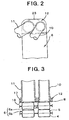
- Pipe connection plate 12 comprises a clad plate, which is covered with a brazing material. As depicted in Figs. 5 and 6 , a width A of pipe connection plate 12 perpendicular to the stacking direction of end plate 8 is less than or equal to a width B of end plate 8.
- the inner circumferential surfaces of pipe insertion hole 13 and 14 of pipe connection plate 12 are formed as tapered surfaces, respectively, so that the diameter of each pipe insertion hole 13 and 14 is increased from a pipe insertion side surface 17 toward an end plate connection side surface 18, as depicted in Fig. 7.
- the parts of heat exchanger 1 is brazed together, substantially simultaneously in a furnace, after respective parts are temporarily assembled.
- a pipe connection portion is temporarily assembled, as depicted in Figs. 8A-8C .
- pipes 10 and 11 are modified to form protruded portions 19 and 20, as depicted in Fig. 8A .
- pipes 10 and 11 are inserted into pipe insertion holes 13 and 14, respectively, of pipe connection plate 12 from pipe insertion side surface 17.
- the pipe insertion depicts of respective pipes 10 and 11 are regulated to a desired depth by protruded portions 19 and 20.
- pipe insertion side surface 17 of pipe connection plate 12 also is substantially flush with an outer surface 27 of the end plate portion of end plate 8, to which an outermost fin 3 is connected.
- pipe insertion holes 13 and 14, which are inserted with inlet and outlet pipes 10 and 11 and are capable of temporarily fixing the end portions of the inserted pipes 10 and 11, are provided on pipe connection plate 12, the outer surfaces of the end portions of the inserted pipes 10 and 11 may be temporarily fixed securely and readily only by inserting the end portions of pipes 10 and 11 into pipe insertion holes 13 and 14. Therefore, the temporarily assembled parts may be brazed readily and substantially simultaneously, in a furnace, without providing a brazing-material member between inner circumferential surfaces of holes and inserted pipes, which has been required in known heat exchangers having raised or elongated portions formed on a plate for pipe connection.
- pipe connection plate 12 may be formed with a reduced size and weight, as compared with known plates formed with raised or elongated portions, and the entire heat exchanger also may be made with a reduced size and weight.
- pipe connection plate 12 is constructed from a clad plate covered with a brazing material, the pipe connection plate 12, end plate 8 and pipes 10 and 11 may be brazed readily and securely. Moreover, because pipe connection plate 12 and end plate 8 are temporarily fixed to each other securely via engaging mechanism 26, both members may be brazed at a desired orientation, more securely.
- pipe insertion holes 13 and 14 are formed as tapered surfaces, for example, by enlarging the diameters of the end portions of inserted pipes 10 and 11 after inserting the pipes 10 and 11, the pipe end portions may be temporarily fixed to pipe connection plate 12, more securely.
- connection portion 21 of end plate 8 Because the end surfaces of the end portions of inserted pipes 10 and 11 are substantially flush with connection side surface 18 of pipe connection plate 12, the entire surface 18 also may be brazed to connection portion 21 of end plate 8 more readily and more securely.
- width A of pipe connection plate 12 is less than or equal to width B of end plate 8
- pipe connection plate 12 does not project from end plate 8 perpendicular to the stacking direction. Therefore, the temporary assemble may be readily placed horizontally in a furnace, and the brazing property may be further improved.
- pipe insertion side surface 17 of pipe connection plate 12 is substantially flush with outer surface 27 of the end plate portion connected with outermost fin 3, a jig for fixing the assembly from both sides in the stacking direction may be less complicated in structure.
- Figs. 9 and 10 depict a pipe connection plate of a stacking-type, multi-flow, heat exchanger, according to a second embodiment of the present invention.
- the inner circumferential surfaces of pipe insertion holes 13 and 14 of pipe connection plate 12 are formed as stepped surfaces 28 and 29.
- Other portions are substantially the same as those in the first embodiment.
- the pipe end portions by enlarging the diameters of the end portions of inserted pipes 10 and 11 in steps, after inserting the pipes 10 and 11, the pipe end portions also may be temporarily, but more securely, fixed to pipe connection plate 12.
Landscapes
- Engineering & Computer Science (AREA)
- Physics & Mathematics (AREA)
- Thermal Sciences (AREA)
- Mechanical Engineering (AREA)
- General Engineering & Computer Science (AREA)
- Heat-Exchange Devices With Radiators And Conduit Assemblies (AREA)
- Details Of Heat-Exchange And Heat-Transfer (AREA)
Abstract
Description
Claims (19)
- A stacking-type, multi-flow, heat exchanger comprising a plurality of heat transfer tubes and a plurality of fins, which are stacked alternately, an end plate disposed at an outermost position of said stacked heat transfer tubes and fins in a stacking direction, and an inlet pipe and an outlet pipe connected to said end plate, said heat exchanger comprising:a pipe connection plate disposed on said end plate, comprising a pipe insertion hole formed therethrough, into which at least one of said inlet and outlet pipes is inserted and which temporarily fixes an end portion of an inserted pipe in said pipe insertion hole.
- The heat exchanger of claim 1, wherein a surface of said pipe connection plate is covered with a brazing material.
- The heat exchanger of claim 1 or 2, wherein said end portion of said inserted pipe is caulked to said pipe connection plate.
- The heat exchanger of any preceding claim, wherein an end surface of said end portion of said inserted pipe is disposed flush with a connection surface of said plate for a pipe connection adjoining said end plate or at a position inward of said connection surface in said pipe insertion hole.
- The heat exchanger of any preceding claim, wherein an inner circumferential surface of said pipe insertion hole is formed as a tapered surface.
- The heat exchanger of any of claims 1 to 4, wherein an inner circumferential surface of said pipe insertion hole is formed as a stepped surface.
- The heat exchanger of any preceding claim, wherein a width of said pipe connection plate perpendicular to the stacking direction of said end plate is less than or equal to a width of said end plate.
- The heat exchanger of any preceding claim, wherein an outer surface of said pipe connection plate is flush with an outer surface of an end plate portion, to which an outermost fin is connected.
- The heat exchanger of any preceding claim, wherein a mechanism for engaging said pipe connection plate with said end plate is disposed between said pipe connection plate and said end plate.
- An air conditioning system comprising the heat exchanger of any preceding claim.
- The air conditioning system of claim 10, wherein a surface of said pipe connection plate is covered with a brazing material.
- The air conditioning system of claim 10 or 11, wherein said end portion of said inserted pipe is caulked to said pipe connection plate.
- The air conditioning system of any of claims 10 to 12, wherein an end surface of said end portion of said inserted pipe is disposed flush with a connection surface of said plate for a pipe connection adjoining said end plate or at a position inward of said connection surface in said pipe insertion hole.
- The air conditioning system of any of claims 10 to 13, wherein an inner circumferential surface of said pipe insertion hole is formed as a tapered surface.
- The air conditioning system of any of claims 10 to 13, wherein an inner circumferential surface of said pipe insertion hole is formed as a stepped surface.
- The air conditioning system of any of claims 10 to 15, wherein a width of said pipe connection plate perpendicular to the stacking direction of said end plate is less than or equal to a width of said end plate.
- The air conditioning system of any of claims 10 to 16, wherein an outer surface of said pipe connection plate is flush with an outer surface of an end plate portion, to which an outermost fin is connected.
- The air conditioning system of any of claims 10 to 17, wherein a mechanism for engaging said pipe connection plate with said end plate is disposed between said pipe connection plate and said end plate.
- A method for manufacturing a heat exchanger comprising the steps ofproviding a plurality of pipes and providing a protruded portion on each of said plurality of pipes;providing a pipe connection plate and forming a plurality of insertion holes through said pipe connection plate, such that each of said plurality of said insertion holes comprises a tapered or stepped surface;inserting each of said plurality of pipes into one of said plurality of insertion holes from a pipe insertion side surface of said pipe connection plate until said protruded portions contact said pipe insertion side surface;caulking an inserted end of each of said plurality of pipes to engage said tapered or stepped surface of one of said plurality of insertion holes; andplacing said heat exchanger into a furnace and brazing each of said plurality of pipes to said tapered or stepped surface of one of said plurality of insertion holes.
Applications Claiming Priority (2)
| Application Number | Priority Date | Filing Date | Title |
|---|---|---|---|
| JP2004156382 | 2004-05-26 | ||
| JP2004156382A JP2005337573A (en) | 2004-05-26 | 2004-05-26 | Heat exchanger |
Publications (2)
| Publication Number | Publication Date |
|---|---|
| EP1600719A2 true EP1600719A2 (en) | 2005-11-30 |
| EP1600719A3 EP1600719A3 (en) | 2006-12-13 |
Family
ID=34941352
Family Applications (1)
| Application Number | Title | Priority Date | Filing Date |
|---|---|---|---|
| EP05253034A Withdrawn EP1600719A3 (en) | 2004-05-26 | 2005-05-18 | Stacking-type, multi-flow, heat exchangers and methods for manufacturing such heat exchangers |
Country Status (6)
| Country | Link |
|---|---|
| US (1) | US7311138B2 (en) |
| EP (1) | EP1600719A3 (en) |
| JP (1) | JP2005337573A (en) |
| CN (1) | CN1707214A (en) |
| CA (1) | CA2508409A1 (en) |
| MY (1) | MY138182A (en) |
Families Citing this family (10)
| Publication number | Priority date | Publication date | Assignee | Title |
|---|---|---|---|---|
| JP2006010102A (en) * | 2004-06-22 | 2006-01-12 | Sanden Corp | Stacked heat exchanger and its manufacturing method |
| JP4797998B2 (en) * | 2006-02-17 | 2011-10-19 | 株式会社デンソー | Heat exchanger piping joint structure and heat exchanger piping assembly method |
| DE102006044091A1 (en) * | 2006-09-20 | 2008-04-03 | Carl Zeiss Microimaging Gmbh | Control module and control system for influencing sample environment parameters of an incubation system, method for controlling a microscope assembly and computer program product |
| US7926854B2 (en) * | 2008-10-10 | 2011-04-19 | Denso International America, Inc. | Pipe joint block for fluid transfer |
| USD624166S1 (en) * | 2009-03-04 | 2010-09-21 | De'longhi Spa | Electric oil filled radiator |
| JP2012141096A (en) * | 2010-12-28 | 2012-07-26 | Mitsubishi Heavy Ind Ltd | Method for manufacturing hot-water heater, and hot-water heater manufactured thereby |
| FR3008783B1 (en) * | 2013-07-19 | 2018-02-23 | Valeo Systemes Thermiques | HEAT EXCHANGER WITH ADAPTER BLOCK FIXED ON AN END PLATE, AND METHOD OF MANUFACTURING THE SAME |
| USD834161S1 (en) * | 2016-02-08 | 2018-11-20 | Tomton S.R.O. | Heat exchanger |
| CN109286276B (en) * | 2017-07-20 | 2020-09-29 | 东芝三菱电机产业系统株式会社 | Totally enclosed rotating electrical machine, tube sheet structure, and method for manufacturing tube sheet structure |
| JP2023001419A (en) * | 2021-06-21 | 2023-01-06 | パナソニックIpマネジメント株式会社 | Heat exchanger and refrigeration system using the same |
Family Cites Families (41)
| Publication number | Priority date | Publication date | Assignee | Title |
|---|---|---|---|---|
| US173101A (en) * | 1876-02-01 | Improvement in oil-stoves | ||
| US484696A (en) * | 1892-10-18 | Henry benbow | ||
| US4487038A (en) * | 1982-04-12 | 1984-12-11 | Diesel Kiki Co., Ltd. | Laminate type evaporator |
| GB2167699B (en) | 1984-12-04 | 1988-04-27 | Sanden Corp | A method for producing a heat exchanger |
| JPS6246195A (en) * | 1985-08-22 | 1987-02-28 | Diesel Kiki Co Ltd | Lamination type heat exchanger |
| JPH069738Y2 (en) * | 1987-01-23 | 1994-03-16 | 株式会社ゼクセル | Brazing structure of pipe material |
| JP2560340B2 (en) * | 1987-08-27 | 1996-12-04 | 日本電装株式会社 | Stacked heat exchanger |
| FR2625172B1 (en) * | 1987-12-24 | 1990-04-20 | Apple Computer France | PACKAGING WITH AIR BAGS |
| JPH0619965Y2 (en) | 1988-01-22 | 1994-05-25 | サンデン株式会社 | Heat exchanger |
| US5088193A (en) | 1988-09-02 | 1992-02-18 | Sanden Corporation | Method for manufacturing a heat exchanger |
| US5148429A (en) | 1988-10-27 | 1992-09-15 | Kabushiki Kaisha Toshiba | Voice data transmission system and method |
| US5099576A (en) | 1989-08-29 | 1992-03-31 | Sanden Corporation | Heat exchanger and method for manufacturing the heat exchanger |
| US5172762A (en) | 1989-10-20 | 1992-12-22 | Sanden Corporation | Heat exchanger |
| JPH03199897A (en) * | 1989-12-27 | 1991-08-30 | Toyo Radiator Co Ltd | Structure of tube for heat exchanger |
| US5119552A (en) | 1990-02-16 | 1992-06-09 | Sanden Corporation | Method for manufacturing header pipe of heat exchanger |
| JP2513332Y2 (en) | 1990-02-22 | 1996-10-02 | サンデン株式会社 | Heat exchanger |
| US5214847A (en) | 1990-03-07 | 1993-06-01 | Sanden Corporation | Method for manufacturing a heat exchanger |
| US5174373A (en) | 1990-07-13 | 1992-12-29 | Sanden Corporation | Heat exchanger |
| JPH04177094A (en) | 1990-11-13 | 1992-06-24 | Sanden Corp | Laminated type heat exchanger |
| DE69233502T2 (en) | 1991-06-11 | 2006-02-23 | Qualcomm, Inc., San Diego | Vocoder with variable bit rate |
| US5255672A (en) | 1991-08-07 | 1993-10-26 | Jinotti Walter J | Dual-purpose catheter assembly |
| JPH0646080A (en) | 1992-07-22 | 1994-02-18 | Toshiba Corp | Delay fluctuation absorption control method |
| JPH06129791A (en) | 1992-10-15 | 1994-05-13 | Sanden Corp | How to fix the heat exchanger and its bracket |
| JPH0755384A (en) | 1993-08-19 | 1995-03-03 | Sanden Corp | Multi-tube heat exchanger |
| US5632331A (en) | 1993-09-30 | 1997-05-27 | Sanden Corporation | Heat exchanger |
| US5513700A (en) * | 1994-07-29 | 1996-05-07 | Ford Motor Company | Automotive evaporator manifold |
| JPH0886536A (en) * | 1994-09-14 | 1996-04-02 | Zexel Corp | Expansion valve mounting member |
| JPH08327276A (en) | 1995-05-30 | 1996-12-13 | Sanden Corp | Multi-tube heat exchanger |
| JPH08327281A (en) | 1995-05-30 | 1996-12-13 | Sanden Corp | Heat exchanger header |
| JP3393957B2 (en) * | 1995-05-30 | 2003-04-07 | サンデン株式会社 | Heat exchanger fluid supply / drain pipe joining method |
| JP3530660B2 (en) | 1995-12-14 | 2004-05-24 | サンデン株式会社 | Heat exchanger tank structure |
| JPH09280781A (en) | 1996-04-17 | 1997-10-31 | Sanden Corp | Multi-tube heat exchanger |
| JPH10185463A (en) | 1996-12-19 | 1998-07-14 | Sanden Corp | Heat exchanger |
| JP3593434B2 (en) | 1997-02-06 | 2004-11-24 | サンデン株式会社 | Heat exchanger unit |
| JP3912836B2 (en) | 1997-02-21 | 2007-05-09 | サンデン株式会社 | Heat exchanger |
| JP3959834B2 (en) * | 1998-03-30 | 2007-08-15 | 株式会社デンソー | Stacked heat exchanger |
| JP4153106B2 (en) | 1998-10-23 | 2008-09-17 | サンデン株式会社 | Heat exchanger |
| JP4328445B2 (en) * | 2000-03-01 | 2009-09-09 | 昭和電工株式会社 | Stacked heat exchanger |
| JP2001289589A (en) * | 2000-04-06 | 2001-10-19 | Sanden Corp | Heat exchanger piping connection structure |
| JP4077610B2 (en) * | 2001-03-16 | 2008-04-16 | カルソニックカンセイ株式会社 | Housingless oil cooler |
| JP4426328B2 (en) | 2004-02-06 | 2010-03-03 | サンデン株式会社 | Laminate heat exchanger |
-
2004
- 2004-05-26 JP JP2004156382A patent/JP2005337573A/en active Pending
-
2005
- 2005-05-18 EP EP05253034A patent/EP1600719A3/en not_active Withdrawn
- 2005-05-24 MY MYPI20052350A patent/MY138182A/en unknown
- 2005-05-24 US US11/135,370 patent/US7311138B2/en not_active Expired - Lifetime
- 2005-05-26 CA CA002508409A patent/CA2508409A1/en not_active Abandoned
- 2005-05-26 CN CN200510075951.6A patent/CN1707214A/en active Pending
Also Published As
| Publication number | Publication date |
|---|---|
| JP2005337573A (en) | 2005-12-08 |
| MY138182A (en) | 2009-05-29 |
| EP1600719A3 (en) | 2006-12-13 |
| US7311138B2 (en) | 2007-12-25 |
| US20050263271A1 (en) | 2005-12-01 |
| CA2508409A1 (en) | 2005-11-26 |
| CN1707214A (en) | 2005-12-14 |
Similar Documents
| Publication | Publication Date | Title |
|---|---|---|
| EP0480628B1 (en) | Heat exchanger | |
| KR100268404B1 (en) | Heat exchanger and its manufacture method | |
| JP5351386B2 (en) | Heat exchanger piping connector | |
| US8205667B2 (en) | Heat exchanger with connector | |
| AU737251B2 (en) | Stepped dimpled mounting brackets for heat exchangers | |
| US5209292A (en) | Condenser header and tank assembly with interference fit baffle | |
| GB2285858A (en) | A two-piece header | |
| EP1541955A2 (en) | Oil-cooler equipped radiator | |
| JP2007139416A (en) | Metal plate for producing flat tube, flat tube, and its manufacturing method | |
| US7311138B2 (en) | Stacking-type, multi-flow, heat exchangers and methods for manufacturing such heat exchangers | |
| JP2004301454A (en) | Header tank for heat exchanger | |
| US5513700A (en) | Automotive evaporator manifold | |
| JPH09126685A (en) | Heat exchanger | |
| US5908070A (en) | Heat exchanger | |
| US7520319B2 (en) | Stacking-type, multi-flow, heat exchanger | |
| KR200159030Y1 (en) | Automotive Evaporator | |
| JP2003106788A (en) | Heat exchanger | |
| JPWO2004081481A1 (en) | Connection structure between heat exchanger tank and connector | |
| EP0798530A1 (en) | Heat exchanger | |
| EP1610080A2 (en) | Stacking-type, multi-flow, heat exchangers and methods for manufacturing such heat exhangers | |
| JPH0571892A (en) | Heat exchanger | |
| JPH08240395A (en) | Heat exchanger | |
| JPH10176894A (en) | Heat exchanger | |
| JPH10206079A (en) | Heat exchanger | |
| JP3517230B2 (en) | Heat exchanger pipe assembly structure |
Legal Events
| Date | Code | Title | Description |
|---|---|---|---|
| PUAI | Public reference made under article 153(3) epc to a published international application that has entered the european phase |
Free format text: ORIGINAL CODE: 0009012 |
|
| AK | Designated contracting states |
Kind code of ref document: A2 Designated state(s): AT BE BG CH CY CZ DE DK EE ES FI FR GB GR HU IE IS IT LI LT LU MC NL PL PT RO SE SI SK TR |
|
| AX | Request for extension of the european patent |
Extension state: AL BA HR LV MK YU |
|
| PUAL | Search report despatched |
Free format text: ORIGINAL CODE: 0009013 |
|
| AK | Designated contracting states |
Kind code of ref document: A3 Designated state(s): AT BE BG CH CY CZ DE DK EE ES FI FR GB GR HU IE IS IT LI LT LU MC NL PL PT RO SE SI SK TR |
|
| AX | Request for extension of the european patent |
Extension state: AL BA HR LV MK YU |
|
| 17P | Request for examination filed |
Effective date: 20070531 |
|
| AKX | Designation fees paid |
Designated state(s): AT BE BG CH CY CZ DE DK EE ES FI FR GB GR HU IE IS IT LI LT LU MC NL PL PT RO SE SI SK TR |
|
| 17Q | First examination report despatched |
Effective date: 20130412 |
|
| STAA | Information on the status of an ep patent application or granted ep patent |
Free format text: STATUS: THE APPLICATION IS DEEMED TO BE WITHDRAWN |
|
| 18D | Application deemed to be withdrawn |
Effective date: 20130823 |