EP1600559A1 - Dispositif de signalisation pour voies de circulation - Google Patents
Dispositif de signalisation pour voies de circulation Download PDFInfo
- Publication number
- EP1600559A1 EP1600559A1 EP04076541A EP04076541A EP1600559A1 EP 1600559 A1 EP1600559 A1 EP 1600559A1 EP 04076541 A EP04076541 A EP 04076541A EP 04076541 A EP04076541 A EP 04076541A EP 1600559 A1 EP1600559 A1 EP 1600559A1
- Authority
- EP
- European Patent Office
- Prior art keywords
- light
- leds
- light pipe
- output window
- carriageway
- Prior art date
- Legal status (The legal status is an assumption and is not a legal conclusion. Google has not performed a legal analysis and makes no representation as to the accuracy of the status listed.)
- Withdrawn
Links
- 239000012780 transparent material Substances 0.000 claims description 17
- 239000003086 colorant Substances 0.000 claims description 9
- 230000000873 masking effect Effects 0.000 claims description 3
- 230000001154 acute effect Effects 0.000 description 4
- 230000004313 glare Effects 0.000 description 3
- 230000011664 signaling Effects 0.000 description 3
- 238000012423 maintenance Methods 0.000 description 2
- 239000000463 material Substances 0.000 description 2
- XLYOFNOQVPJJNP-UHFFFAOYSA-N water Substances O XLYOFNOQVPJJNP-UHFFFAOYSA-N 0.000 description 2
- XUIMIQQOPSSXEZ-UHFFFAOYSA-N Silicon Chemical compound [Si] XUIMIQQOPSSXEZ-UHFFFAOYSA-N 0.000 description 1
- NIXOWILDQLNWCW-UHFFFAOYSA-N acrylic acid group Chemical group C(C=C)(=O)O NIXOWILDQLNWCW-UHFFFAOYSA-N 0.000 description 1
- 239000000853 adhesive Substances 0.000 description 1
- 238000004026 adhesive bonding Methods 0.000 description 1
- 230000001070 adhesive effect Effects 0.000 description 1
- 229910052782 aluminium Inorganic materials 0.000 description 1
- XAGFODPZIPBFFR-UHFFFAOYSA-N aluminium Chemical compound [Al] XAGFODPZIPBFFR-UHFFFAOYSA-N 0.000 description 1
- 238000005452 bending Methods 0.000 description 1
- 230000008878 coupling Effects 0.000 description 1
- 238000010168 coupling process Methods 0.000 description 1
- 238000005859 coupling reaction Methods 0.000 description 1
- 238000005516 engineering process Methods 0.000 description 1
- 239000011521 glass Substances 0.000 description 1
- 229910052736 halogen Inorganic materials 0.000 description 1
- 150000002367 halogens Chemical class 0.000 description 1
- 210000003128 head Anatomy 0.000 description 1
- 230000017525 heat dissipation Effects 0.000 description 1
- 238000005286 illumination Methods 0.000 description 1
- 239000003550 marker Substances 0.000 description 1
- 229910052751 metal Inorganic materials 0.000 description 1
- 239000002184 metal Substances 0.000 description 1
- 230000003287 optical effect Effects 0.000 description 1
- 239000003973 paint Substances 0.000 description 1
- 229920000515 polycarbonate Polymers 0.000 description 1
- 239000004417 polycarbonate Substances 0.000 description 1
- 230000003252 repetitive effect Effects 0.000 description 1
- 229910052710 silicon Inorganic materials 0.000 description 1
- 239000010703 silicon Substances 0.000 description 1
Images

Classifications
-
- G—PHYSICS
- G02—OPTICS
- G02B—OPTICAL ELEMENTS, SYSTEMS OR APPARATUS
- G02B6/00—Light guides; Structural details of arrangements comprising light guides and other optical elements, e.g. couplings
- G02B6/0001—Light guides; Structural details of arrangements comprising light guides and other optical elements, e.g. couplings specially adapted for lighting devices or systems
- G02B6/0096—Light guides; Structural details of arrangements comprising light guides and other optical elements, e.g. couplings specially adapted for lighting devices or systems the lights guides being of the hollow type
-
- E—FIXED CONSTRUCTIONS
- E01—CONSTRUCTION OF ROADS, RAILWAYS, OR BRIDGES
- E01F—ADDITIONAL WORK, SUCH AS EQUIPPING ROADS OR THE CONSTRUCTION OF PLATFORMS, HELICOPTER LANDING STAGES, SIGNS, SNOW FENCES, OR THE LIKE
- E01F9/00—Arrangement of road signs or traffic signals; Arrangements for enforcing caution
- E01F9/20—Use of light guides, e.g. fibre-optic devices
-
- F—MECHANICAL ENGINEERING; LIGHTING; HEATING; WEAPONS; BLASTING
- F21—LIGHTING
- F21W—INDEXING SCHEME ASSOCIATED WITH SUBCLASSES F21K, F21L, F21S and F21V, RELATING TO USES OR APPLICATIONS OF LIGHTING DEVICES OR SYSTEMS
- F21W2111/00—Use or application of lighting devices or systems for signalling, marking or indicating, not provided for in codes F21W2102/00 – F21W2107/00
- F21W2111/02—Use or application of lighting devices or systems for signalling, marking or indicating, not provided for in codes F21W2102/00 – F21W2107/00 for roads, paths or the like
-
- F—MECHANICAL ENGINEERING; LIGHTING; HEATING; WEAPONS; BLASTING
- F21—LIGHTING
- F21Y—INDEXING SCHEME ASSOCIATED WITH SUBCLASSES F21K, F21L, F21S and F21V, RELATING TO THE FORM OR THE KIND OF THE LIGHT SOURCES OR OF THE COLOUR OF THE LIGHT EMITTED
- F21Y2103/00—Elongate light sources, e.g. fluorescent tubes
-
- F—MECHANICAL ENGINEERING; LIGHTING; HEATING; WEAPONS; BLASTING
- F21—LIGHTING
- F21Y—INDEXING SCHEME ASSOCIATED WITH SUBCLASSES F21K, F21L, F21S and F21V, RELATING TO THE FORM OR THE KIND OF THE LIGHT SOURCES OR OF THE COLOUR OF THE LIGHT EMITTED
- F21Y2115/00—Light-generating elements of semiconductor light sources
- F21Y2115/10—Light-emitting diodes [LED]
Definitions
- the present invention relates to a carriageway-marking device and system.
- edges of a carriageway are commonly marked, in addition to lines on the roadway, by a series of interspaced retro-reflective elements, typically white on the vehicle off side and red on the vehicle near side.
- the performance of such elements is poor because they only become visible when struck by the light of the incoming vehicle. This might happen too late in case of high speed, sharp curves, hills and similar. In case of low visibility, especially due to fog, the performance may become extremely poor.
- Lighting devices are also employed sometimes, such as at deviations or dangerous bends. They normally include a row of individual lamps, that may be continuously lit or flashed in series. In either case, the individual lamps may only provide a non-continuous marking. Moreover, since the lights need to be mounted at a height comparable to the head of the driver, when the vehicle passes nearby each lamp, he/she suffers glare or, at least, is disturbed by the intense light.
- a light pipe carriageway-marking system is also known (see e.g. WO 95/30218 and the prior art referred to thereby), comprising a plurality of light pipes extending alongside the road, each provided with one discharge or halogen lamp and an associated yellow filter at one end or at both ends thereof.
- the light from the lamp after passing through the filter, illuminates the light pipe walls while traveling along the light pipe.
- the light pipe is therefore yellow illuminated, thus highly visible even in fog conditions.
- the present invention relates to a carriageway-marking device, comprising: a tubular light pipe having a longitudinally extending light output window and a light extractor means; and a light projector coupled to a first end of said light pipe for projecting light thereinto, characterized in that said light projector comprises a plurality of Light Emitting Diodes (LEDs).
- LEDs Light Emitting Diodes
- LEDs as the light source provides for low voltage power supply, long lifetime, low service and maintenance of the carriageway-marking device and system.
- LEDs By providing for a plurality of LEDs, not all of which need to be illuminated at once, light of different intensity may be provided, as best suited for the visibility conditions. Also, LEDs providing light of different colors may be used, thus making the carriageway-marking device also useful as a signaling device.
- LED technology allows for remote control and surveillance of the light projector.
- the light output window preferably extends 180° circumferentially around the light pipe, and is centered about a plane deviating downwards from the horizontal, so as to be orientable towards the carriageway edge.
- the light is preferably emitted from the output window at an angle not greater than 30° with respect to the longitudinal axis of the light pipe. Such angle range allows high visibility of the marking device, while avoiding direct glare in the eyes of the driver from the immediately adjacent length of the marking device.
- Each of the LEDs is preferably provided with an associated parabolic reflector to improve lighting control of the device.
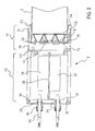
- a carriageway-marking device 1 that generally comprises a tubular light pipe 2 and a light projector 3 at one end of light pipe 2.
- light pipe 2 comprises a supporting transparent material 4, shaped into a tubular form.
- the supporting transparent material 4 is selected to be flexible enough so as to allow bending according to radiuses of curvature as are typical of roads.
- a coextruded polycarbonate and acrylic material is a suitable supporting transparent material because it has a suitable life of at least ten years, and a suitable strength.
- the supporting transparent material 4 is also preferably UV-resistant.
- the supporting transparent material 4 is lined with a micro-structured transparent material 5.
- the micro-structured transparent material 5 is more specifically arranged with its micro-structures extending longitudinally and facing outwards.
- a particularly suited micro-structured transparent material 5 is that commercially available as ScotchTM Optical Lighting Film 2301 from 3M Company of St. Paul, Minnesota, USA.
- a circumferential portion 6 of light pipe 2, referred to herein as light extractor portion, is made partly specularly reflective and partly diffusively reflective, so that the angles of light rays impinging thereupon are partly deviated to a direction allowing them to be emitted from the remaining circumferential portion of light pipe 2, referred to herein as light output window 5a.
- the masking 7 may be either a mirror film, or a white film, according to the length of the light pipe 2. As will be appreciated by those skilled in the art, in a comparatively long light pipe 2, the light guiding requirement will prevail and thus a mirror film will be desirable, while in a comparatively short light pipe 2, the light diffusing requirement will prevail and thus a white film will be desirable.
- micro-structured transparent material 5 bears, at the light extractor portion 6, a plurality of diffusely reflective elements, e.g. silk-screen printed white paint dots.
- the diffusely reflective elements more specifically comprise a plurality of rows 8 of dots extending transversally to the longitudinal axis A of light pipe 2, less spaced apart going from the light input end of the light pipe 2 (that is the end that is coupled to light projector 3), towards its center.
- the predetermined configuration of diffusely reflective elements 8 is obtained by applying the principles disclosed in WO 02/23084.
- the micro-structured transparent material 5 may only be provided at the light output window 5a, while providing at the light extractor portion 6, a sheet of dot printed 3MTM Radiant Mirror Film available from 3M Company of St. Paul, Minnesota, USA laminated onto the transparent supporting material 4.
- Each of light output window 5a and light extractor portion 6 preferably extends 180° in cross-section. More precisely, the light output window 5a is centered about a plane deviating 45° downwards from a horizontal plane when the carriageway-marking device 1 is its mounted condition. The light exiting the light pipe 2 from light output window 5a is thus conveniently directed towards the carriageway edge, thus improving the efficiency of the carriageway-marking device.
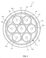
- light projector 3 it comprises a plurality of LEDs 9. Seven LEDs, labelled as 91-97 in figure 3, are shown in the figures, arranged at the corners and center of a (virtual) hexagon.
- LEDs 91-93 Three of the LEDs arranged at the corners are red LEDs 91-93, while the remaining LEDs at the corners and the central LED are green LEDs 94-97. More in particular, the LEDs at the corners 91-96 of the hexagon are alternately green and red ones.
- Each LED 91-97 is placed at the focus of a respective parabolic reflector 10 (labelled as 101-107 in figure 3).
- Each parabolic reflector 10 has a longitudinal axis parallel to the longitudinal axis A of the light pipe 2.
- Each parabolic reflector 10 is sized so that the light beam from the respective LED 9 forms a cone (more precisely, a frustum of a cone) having an aperture of 30°. That is, the light cone from each LED/reflector assembly 9,10 is directed into the light pipe 2 under angles within 0° and 15° with respect to the longitudinal axis A of the light pipe 2 and thus with respect to the walls of the light pipe 2.
- the LEDs 9 and their respective parabolic reflectors 10 are housed within an optics body portion 11 of the light projector 3, in turn coupled with a power supply/control electronics body portion 12 of the light projector 3 with interposition of a gasket 13, ensuring tightness against entry of moisture, water, and dirt that could damage the LEDs 9.
- Coupling of optics body portion 11 and supply/control body portion 12 may be accomplished through screws (not shown) threaded into bores 14, but any fastening means, such as a press-fit or an adhesive, can be used instead.
- Optics body portion 11 comprises a cup-shaped member 15, provided with heat exchange fins 16 at its bottom periphery.
- the internal bottom of cup-shaped member 15 is provided with a series of annular grooves 17, also for heat exchange, and with a pair of through holes 18 for passing the wires (not shown) into the supply/control body portion 12.
- Optics body portion 11 further comprises an aluminum LED holder plate 19, to which LEDs 9 and their associated parabolic reflectors 10 are attached, e.g. by gluing as shown, by screws, or similar.
- LED holder plate 19 is further provided with a plurality of holes 20 for passing the wires (not shown) for inter-connection of the electric pins of the LEDs 9, as better specified hereinafter.
- a collar 21 fits into cup-shaped member 15, with interposition of a rectangular-section silicon gasket 22 at the bottom of the collar 21.
- the internal surface of collar 21 has a pair of ring shaped grooves 23 for receiving a pair of O-rings 24.
- O-rings 24 create a suitable mechanical hold on the light pipe 2, and further provide for suitable tightness against entry of moisture, water, and dirt into the optics body portion 11.
- the LEDs 9 are electrically connected with each other and with supply/control body portion 12. More specifically, the three red LEDs 91-93 are electrically connected in parallel and to a first power and drive unit 26, and the four green LEDs 94-97 are electrically connected in parallel and to a second power and drive unit 27.
- Each power and drive unit 26, 27 may comprise a microchip suitable for providing a feedback about the proper operation and instantaneous output of the LEDs it is connected with.
- a single power and drive unit may be used, provided with suitable switching means for separately controlling the two sets of colored LEDs 91-93, 94-97. It is however to be noted that the two low wattage power and drive units 26, 27 will have a longer average life than a comparatively high wattage single power and drive unit.
- Power and drive units 26, 27 are fastened to an L-shaped metal or insulating sheet 28 that is in turn fastened, such as screwed or glued, to a removable cap 29 of supply/control body portion 12.
- Cap 29 is secured to supply/control body portion 12 e.g. by screws (not shown) threaded into holes 30 of cap 29 and corresponding holes (not shown) of supply/control body portion 12.
- Power and drive units 26, 27 are thus housed within the cylindrical cavity of supply/control body portion 12.
- Supply/control body portion 12 is sized with respect to power and drive units 26, 27 so as to ensure proper heat dissipation.
- Cap 29 is more precisely provided with a central projection 31 whose edge forms a groove 32 for receiving an O-ring 33 for tightness of supply/control body portion 12.
- a pair of through holes 34 fitted with wire-holders 35 is provided into cap 29 for passing tri-filament electric wires 36 for power supply and earth connection of power and drive units 26, 27.
- a further through hole may be provided for passing a signal cable to a remote unit for controlling the light projector 3.
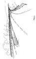
- a plurality of carriageway-marking devices 1 are fastened, closely spaced, to a guard-rail of a road by any suitable means, thus forming a carriageway-marking system according to the invention.
- the operation of the carriageway-marking device 1 of the invention will be easily appreciated by those skilled in the art.
- the light from the light projector 3 is guided along light pipe 2 and emitted through its output window 5a.
- the light from LEDs 9 is emitted through the output window 5a under an acute angle with respect to the longitudinal axis A of light pipe 2.
- the preferred emission acute angle is of 30°, that is the light is emitted from parallel to the light pipe 2 up to 30° skewed outwards of it.
- An acute angle of light emission is particularly suitable for carriageway-marking purposes. Indeed, the light is directed towards the driver and skewed towards the edge of the carriageway.
- the carriageway-marking device 1 forms a continuous highly visible line (as opposed to small spots of retro-reflective markers) and effectively illuminates the carriageway edge with high visibility in any weather condition, in particular the device is able to "cut" through fog.
- the device has thus a high luminous efficiency, fairly higher also than the known light pipe carriageway marking system referred to above, that used high wattage light sources and had no control of the light output angle, thus having a reduced luminous efficiency.
- the carriageway-marking device 1 may be further used as a signaling device.
- Remote control may be accomplished by wired or wireless connection of the carriageway-marking device 1 (and preferably all such devices 1 extending along a given road or road network as shown in Fig. 4) to a control station.
- a control station will be for example located at a police station, at a fire-station, at superhighway tollbooths and so on.
- the mutual arrangement of the LEDs 9 as shown is such that the light cones from individual LEDs 9 are slightly overlapped before entry into the light pipe 2, so that the colors will effectively combine into yellow before striking the walls 5, 6 of the light pipe 2. While this provision is not strictly necessary, it makes it easier to design the carriageway-marking device 1 and especially its light extractor portion 6 to obtain the desired light exit angle.
- each of the plurality of LEDs 9 is an RGB LED, capable of providing light of a full range of colors. In addition to red, green and yellow light, white light may be thus easily obtained, e.g. for use as a marker on the left side of carriageway, as requested by many traffic standards. It will be understood that the two power and drive units 26, 27 will then be replaced by a single one.
- the plurality of LEDs 9 comprises at least one LED for each of a primary color of a set of primary colors, e.g. red-green-blue, cyan-magenta-yellow.
- a primary color of a set of primary colors e.g. red-green-blue, cyan-magenta-yellow.
- any visible color, including white may be obtained.
- cyan-magenta-yellow pure white may not be obtained, still a suitably light yellow may.
- the two power and drive units 26, 27 shown in the figures will be replaced by a plurality of power and drive units, providing for control of the LEDs of individual colors, or again by a single power and drive unit having suitable switching means.
- the number of monochromatic or multi-chip LEDs may differ from seven, according to the required colors, the power output of each color, as well as the size and shape of the light pipe 2.
- red LEDs and green LEDs When red LEDs and green LEDs are used, to obtain the best hue of red, green and yellow light, the green LEDs should outnumber the red LEDs by one. Three or five LEDs might be too few to properly cover the entire cross-section of light pipe 2, while more than seven LEDs would increase the power consumption.
- carriageway-marking devices 1 When a plurality of carriageway-marking devices 1 are arranged into a system, they may be commonly controlled, or each of them may be independently controlled. It is thus possible to easily implement e.g. waves of lights switching on in a repetitive sequence, so as to further improve visibility of highly dangerous bends, entry into tunnels and so on.
- the light pipe may have a diameter of a few centimeters, and a length of a few meters.
- a light projector identical to light projector 3 may be placed at the second end of light pipe 2 for lengths of 4 meters and higher.
- the cross-section of the carriageway-marking device 1 may depart from being circular as shown, e.g. it may be elliptical, rectangular or of other shapes.
- a circular cross-section easily allows a packed arrangement of the LEDs so as to obtain a uniform illumination of the entire cross-section of the light pipe 2.
- the light output window 5a may extend more than 180° and be centered about the vertical.
- Luminosity at 1 meter of prototypes of the invention each provided with four green LEDs and three red LEDs, each having a nominal power of 1 W (1,2 W as measured) was measured.
- the various LEDs were those having a hexagonal PCB available from Lumileds Lighting, LLC of San Jose, CA, U.S.A., under the designation "Luxeon Star ".
- the diameter of the light pipe 2 was of 110 mm. The results are as set in the table below.
- Length of light pipe (meters) Number of projectors Luminosity at 1 meter (lux/square meter) Yellow light Red light Green light 2 1 3 4 3.5 3 1 2 2.6 2.3 4 2 12 15.6 14 Length of light pipe (meters) Number of projectors Luminosity at 1 meter (lux/square meter) Yellow light Red light Green light 5 2 9 11.7 10.5 6 2 6 8 7
- the devices having two projectors provide enough luminosity for road use under the European standard, that requires at least 5 lux at 1 meter from the light source. It will be recognized that a length of the light pipe 2 of 6 meters will be preferred, because fewer devices will be required in a system as that shown in fig. 4.
Priority Applications (5)
| Application Number | Priority Date | Filing Date | Title |
|---|---|---|---|
| EP04076541A EP1600559A1 (fr) | 2004-05-26 | 2004-05-26 | Dispositif de signalisation pour voies de circulation |
| US11/569,312 US20080291664A1 (en) | 2004-05-26 | 2005-04-14 | Carriageway-Marking Device and System |
| JP2007515080A JP2008507639A (ja) | 2004-05-26 | 2005-04-14 | 道路標示装置およびシステム |
| CNA2005800169466A CN1957142A (zh) | 2004-05-26 | 2005-04-14 | 行车道标示装置和系统 |
| PCT/US2005/012908 WO2005118956A1 (fr) | 2004-05-26 | 2005-04-14 | Appareil de signalisation de chaussee et systeme |
Applications Claiming Priority (1)
| Application Number | Priority Date | Filing Date | Title |
|---|---|---|---|
| EP04076541A EP1600559A1 (fr) | 2004-05-26 | 2004-05-26 | Dispositif de signalisation pour voies de circulation |
Publications (1)
| Publication Number | Publication Date |
|---|---|
| EP1600559A1 true EP1600559A1 (fr) | 2005-11-30 |
Family
ID=34928243
Family Applications (1)
| Application Number | Title | Priority Date | Filing Date |
|---|---|---|---|
| EP04076541A Withdrawn EP1600559A1 (fr) | 2004-05-26 | 2004-05-26 | Dispositif de signalisation pour voies de circulation |
Country Status (5)
| Country | Link |
|---|---|
| US (1) | US20080291664A1 (fr) |
| EP (1) | EP1600559A1 (fr) |
| JP (1) | JP2008507639A (fr) |
| CN (1) | CN1957142A (fr) |
| WO (1) | WO2005118956A1 (fr) |
Cited By (3)
| Publication number | Priority date | Publication date | Assignee | Title |
|---|---|---|---|---|
| EP1955099A1 (fr) * | 2005-11-30 | 2008-08-13 | 3M Innovative Properties Company | Guide de lumiere et appareil d eclairage comprenant celui-ci |
| WO2015133905A1 (fr) * | 2014-03-06 | 2015-09-11 | Silicon Hill B.V. | Dispositif d'éclairage |
| CN117541997A (zh) * | 2024-01-10 | 2024-02-09 | 泰安万川电器设备有限公司 | 一种基于图像特征的巷道安全预警方法及系统 |
Families Citing this family (14)
| Publication number | Priority date | Publication date | Assignee | Title |
|---|---|---|---|---|
| US20100117934A1 (en) * | 2008-11-06 | 2010-05-13 | Production Resource Group L.L.C | Moving Lights forming Pixels of a Video |
| CN201487668U (zh) * | 2009-09-09 | 2010-05-26 | 珠海晟源同泰电子有限公司 | 集束组合led照明光源 |
| CN102141231A (zh) * | 2010-01-29 | 2011-08-03 | 欧司朗光电半导体有限公司 | 光源 |
| TW201128116A (en) * | 2010-02-11 | 2011-08-16 | Jia-Ye Wu | LED lamp set |
| CN102094398A (zh) * | 2011-01-29 | 2011-06-15 | 毕海云 | 投光式地面交通标志、标线装置 |
| US9817728B2 (en) | 2013-02-01 | 2017-11-14 | Symbolic Io Corporation | Fast system state cloning |
| US9304703B1 (en) | 2015-04-15 | 2016-04-05 | Symbolic Io Corporation | Method and apparatus for dense hyper IO digital retention |
| US10133636B2 (en) | 2013-03-12 | 2018-11-20 | Formulus Black Corporation | Data storage and retrieval mediation system and methods for using same |
| SG10201405166TA (en) * | 2014-08-24 | 2016-03-30 | 3M Innovative Properties Co | A lighting system |
| US9803823B2 (en) * | 2015-01-28 | 2017-10-31 | Osram Sylvania Inc. | Vehicle LED bulb with polygonal light guide |
| US10061514B2 (en) | 2015-04-15 | 2018-08-28 | Formulus Black Corporation | Method and apparatus for dense hyper IO digital retention |
| US10572186B2 (en) | 2017-12-18 | 2020-02-25 | Formulus Black Corporation | Random access memory (RAM)-based computer systems, devices, and methods |
| US10725853B2 (en) | 2019-01-02 | 2020-07-28 | Formulus Black Corporation | Systems and methods for memory failure prevention, management, and mitigation |
| CN111636336B (zh) * | 2020-06-09 | 2021-10-08 | 湖州越彬智能科技有限公司 | 一种防攀爬隔离栏杆 |
Citations (3)
| Publication number | Priority date | Publication date | Assignee | Title |
|---|---|---|---|---|
| WO1995030218A1 (fr) | 1994-04-29 | 1995-11-09 | Minnesota Mining And Manufacturing Company | Systeme de conduits lumineux routiers perfectionnes |
| JP2000257032A (ja) * | 1999-03-11 | 2000-09-19 | Kictec Inc | 走行誘導装置 |
| WO2002023084A1 (fr) | 2000-09-15 | 2002-03-21 | 3M Innovative Properties Company | Extracteur de lumiere pour lampe a guide d'ondes optiques |
Family Cites Families (6)
| Publication number | Priority date | Publication date | Assignee | Title |
|---|---|---|---|---|
| US5258896A (en) * | 1992-06-04 | 1993-11-02 | Minnesota Mining And Manufacturing Company | Line light source |
| US6031958A (en) * | 1997-05-21 | 2000-02-29 | Mcgaffigan; Thomas H. | Optical light pipes with laser light appearance |
| US20020176259A1 (en) * | 1999-11-18 | 2002-11-28 | Ducharme Alfred D. | Systems and methods for converting illumination |
| US6481882B1 (en) * | 2000-05-04 | 2002-11-19 | 3M Innovative Properties Company | Light pipe fixture with internal extractor |
| US6796686B2 (en) * | 2002-10-04 | 2004-09-28 | Tir Systems Ltd. | Color-corrected hollow prismatic light guide luminaire |
| US7125147B2 (en) * | 2004-11-18 | 2006-10-24 | Waring Patrick S | Method and apparatus for directing light from a light source |
-
2004
- 2004-05-26 EP EP04076541A patent/EP1600559A1/fr not_active Withdrawn
-
2005
- 2005-04-14 JP JP2007515080A patent/JP2008507639A/ja not_active Withdrawn
- 2005-04-14 WO PCT/US2005/012908 patent/WO2005118956A1/fr active Application Filing
- 2005-04-14 US US11/569,312 patent/US20080291664A1/en not_active Abandoned
- 2005-04-14 CN CNA2005800169466A patent/CN1957142A/zh active Pending
Patent Citations (3)
| Publication number | Priority date | Publication date | Assignee | Title |
|---|---|---|---|---|
| WO1995030218A1 (fr) | 1994-04-29 | 1995-11-09 | Minnesota Mining And Manufacturing Company | Systeme de conduits lumineux routiers perfectionnes |
| JP2000257032A (ja) * | 1999-03-11 | 2000-09-19 | Kictec Inc | 走行誘導装置 |
| WO2002023084A1 (fr) | 2000-09-15 | 2002-03-21 | 3M Innovative Properties Company | Extracteur de lumiere pour lampe a guide d'ondes optiques |
Non-Patent Citations (1)
| Title |
|---|
| PATENT ABSTRACTS OF JAPAN vol. 2000, no. 12 3 January 2001 (2001-01-03) * |
Cited By (6)
| Publication number | Priority date | Publication date | Assignee | Title |
|---|---|---|---|---|
| EP1955099A1 (fr) * | 2005-11-30 | 2008-08-13 | 3M Innovative Properties Company | Guide de lumiere et appareil d eclairage comprenant celui-ci |
| EP1955099A4 (fr) * | 2005-11-30 | 2008-11-05 | 3M Innovative Properties Co | Guide de lumiere et appareil d eclairage comprenant celui-ci |
| WO2015133905A1 (fr) * | 2014-03-06 | 2015-09-11 | Silicon Hill B.V. | Dispositif d'éclairage |
| NL2012379A (en) * | 2014-03-06 | 2015-11-17 | Silicon Hill Bv | Light device. |
| CN117541997A (zh) * | 2024-01-10 | 2024-02-09 | 泰安万川电器设备有限公司 | 一种基于图像特征的巷道安全预警方法及系统 |
| CN117541997B (zh) * | 2024-01-10 | 2024-03-12 | 泰安万川电器设备有限公司 | 一种基于图像特征的巷道安全预警方法及系统 |
Also Published As
| Publication number | Publication date |
|---|---|
| WO2005118956A1 (fr) | 2005-12-15 |
| US20080291664A1 (en) | 2008-11-27 |
| CN1957142A (zh) | 2007-05-02 |
| JP2008507639A (ja) | 2008-03-13 |
Similar Documents
| Publication | Publication Date | Title |
|---|---|---|
| US20080291664A1 (en) | Carriageway-Marking Device and System | |
| US7755513B2 (en) | Visual navigational aids based on high intensity LEDS | |
| US7192155B2 (en) | Airfield edge-light utilizing a side-emitting light source | |
| US8287147B2 (en) | LED based omni-directional light engine | |
| US7866845B2 (en) | Optical device for mixing and redirecting light | |
| US7357530B2 (en) | Lighting apparatus for navigational aids | |
| US20230024141A1 (en) | System and Method for Driving and Controlling Light Sources | |
| JP2010534908A (ja) | 街路照明装置 | |
| JP2000511333A (ja) | 信号、識別または標識のための発光装置 | |
| CN1216094A (zh) | 照明设备 | |
| US9541258B2 (en) | Lens for wide lateral-angle distribution | |
| KR20190099026A (ko) | 고정된 광학기 및 가변 방출 패턴을 갖는 led 조명 모듈 | |
| US20100277902A1 (en) | Light emitting diode lamp for street lighting with changeable emission color | |
| JP2002008414A (ja) | 標識灯用ランプ及び航空標識灯 | |
| EP1945007B1 (fr) | Procédé d'optimisation de débit de dispositifs d'éclairage LED | |
| US20130301262A1 (en) | Lighting device and a luminaire comprising the lighting device | |
| US20230265978A1 (en) | Post top led lamp optics | |
| JP2009245621A (ja) | 屋外照明灯具ユニット、及び屋外照明灯具 | |
| FI108160B (fi) | Maa- ja vesiliikenteen ohjausvalojen valaisin | |
| AU3637400A (en) | LED illuminated lamp assembly |
Legal Events
| Date | Code | Title | Description |
|---|---|---|---|
| PUAI | Public reference made under article 153(3) epc to a published international application that has entered the european phase |
Free format text: ORIGINAL CODE: 0009012 |
|
| AK | Designated contracting states |
Kind code of ref document: A1 Designated state(s): AT BE BG CH CY CZ DE DK EE ES FI FR GB GR HU IE IT LI LU MC NL PL PT RO SE SI SK TR |
|
| AX | Request for extension of the european patent |
Extension state: AL HR LT LV MK |
|
| 17P | Request for examination filed |
Effective date: 20060515 |
|
| AKX | Designation fees paid |
Designated state(s): AT BE BG CH CY CZ DE DK EE ES FI FR GB GR HU IE IT LI LU MC NL PL PT RO SE SI SK TR |
|
| 17Q | First examination report despatched |
Effective date: 20070205 |
|
| STAA | Information on the status of an ep patent application or granted ep patent |
Free format text: STATUS: THE APPLICATION HAS BEEN WITHDRAWN |
|
| 18W | Application withdrawn |
Effective date: 20080922 |