EP1600554A2 - Schuhwalze - Google Patents
Schuhwalze Download PDFInfo
- Publication number
- EP1600554A2 EP1600554A2 EP05102256A EP05102256A EP1600554A2 EP 1600554 A2 EP1600554 A2 EP 1600554A2 EP 05102256 A EP05102256 A EP 05102256A EP 05102256 A EP05102256 A EP 05102256A EP 1600554 A2 EP1600554 A2 EP 1600554A2
- Authority
- EP
- European Patent Office
- Prior art keywords
- shoe roll
- roll according
- shoe
- jacket
- drive
- Prior art date
- Legal status (The legal status is an assumption and is not a legal conclusion. Google has not performed a legal analysis and makes no representation as to the accuracy of the status listed.)
- Granted
Links
Images


Classifications
-
- D—TEXTILES; PAPER
- D21—PAPER-MAKING; PRODUCTION OF CELLULOSE
- D21G—CALENDERS; ACCESSORIES FOR PAPER-MAKING MACHINES
- D21G1/00—Calenders; Smoothing apparatus
- D21G1/006—Calenders; Smoothing apparatus with extended nips
-
- D—TEXTILES; PAPER
- D21—PAPER-MAKING; PRODUCTION OF CELLULOSE
- D21F—PAPER-MAKING MACHINES; METHODS OF PRODUCING PAPER THEREON
- D21F3/00—Press section of machines for making continuous webs of paper
- D21F3/02—Wet presses
- D21F3/0209—Wet presses with extended press nip
- D21F3/0218—Shoe presses
-
- D—TEXTILES; PAPER
- D21—PAPER-MAKING; PRODUCTION OF CELLULOSE
- D21G—CALENDERS; ACCESSORIES FOR PAPER-MAKING MACHINES
- D21G1/00—Calenders; Smoothing apparatus
- D21G1/0006—Driving arrangements
Definitions
- the invention relates to a shoe roll for the production and / or treatment a material web, in particular for a calender, with an axially displaceable Sheath and a drive for the rotation of the jacket.
- Such a shoe roll can, for example, with a particular overhead Heating roller cooperate, and during normal operation
- the shoe roll shell can only be replaced by the hot counter roll are driven. But it must not now to a direct Contact between the shoe roll shell and the heating roller come. Between these must always be the relevant material or paper web, otherwise the shoe roll shell would be too hot. Accordingly, a Drive required to move the shoe roller to the speed of the heated Accelerate counter roll.
- Another problem is the wear of the shoe roll shell. Such wear could possibly be replaced by a repeated axial Oppose moving the sheath. After the shoe roll coat driven or first accelerated to the paper speed but this is not readily possible.
- the invention has for its object to provide an improved shoe roll of the type mentioned, in which the aforementioned problems are eliminated.
- This object is achieved in that the rotary drive is designed so that it compensates for a respective axial movement of the shell or tolerated.
- the jacket is preferably on both edges via clamping disks stored, wherein the clamping disks are driven by the rotary drive.
- the jacket is also in an advantageous manner over the clamping washers axially movable.
- the shoe roll may for example be designed so that the jacket to about ⁇ 50 mm axially displaceable
- the clamping disks can be driven from the outside and / or from the inside.
- Shoe roll includes the rotary drive both on the leader side and on the drive side in each case at least one electric drive motor.
- the rotary drive For example, at least one PTO, at least one clutch and / or comprise at least one splined shaft.
- the rotary drive comprises at least two electrical Drive motors whose drive shafts torque-locking with each other are connected.
- the drive shaft for example, via a propeller shaft with Metal bellows couplings be mechanically interconnected.
- a respective drive shaft Preferably sits on a respective drive shaft in each case a disc-shaped electric drive motor.
- the cooling for example, with fluid, gas (air), water and preferably with oil, since at a respective leakage oil in the Coat is not contaminated.
- Shoe roll is in the roll inside the clamping disks each one as a ring gear provided gear provided, in which a flying pinion engages.
- These pinions can each be mounted in a displaceable carrier.
- One respective carrier can on the one hand on a non-rotating part of the respective Clamping device attached to the jacket and on the other hand in one Be guided support body.
- the pinions can each sit on a pinion shaft, which via a spline slidable with a respective, mounted in a support body Intermediate shaft is coupled.
- the intermediate waves can each have a Metal bellows coupling be coupled to the respective drive shaft.
- the location of the teeth of the internally toothed cavity should be relative to The teeth of the pinion should not change as much as possible in order to avoid wear as well as damage to the teeth. Possible cause for one Change in position is a wobbling movement of the clamping disks and / or a respective deflection of the pinion shafts.
- a respective pinion shaft firmly mounted on the bearing sleeve, on which the respective clamping sleeve is stored.
- a tumbling motion is thus excluded. It can, for example be provided two bearing points in the axial direction, for example two deep groove ball bearings side by side, which are axially biased to the Reduce the game to an acceptable level. With the appropriate game also a respective wobbling motion is avoided.
- the electric drive motors can in the stator of a respective Drive motor prevail overpressure, this pressure preferably slightly higher than the internal roll pressure.
- the jacket is relative to a fixed support body of the roller radially adjustable, so there is a so-called inner hub.
- the nip can thus closed or opened by raising or lowering the shoe become.
- lubricating oil of the jacket is no longer in the desired manner stripped, which can lead to damage. It can therefore in the circumferential direction before and / or behind a press shoe, preferably in at least one upper quadrant of the roller, an oil scraper bar be provided.
- This ⁇ labstreifance is then advantageously with an open nip formed on the mating element can be pressed against the mantle.
- an oil pan is provided into which the stripped oil due to gravity and passes over this oil in the cooling oil circuit is traceable.
- At least one pressing element acting on the jacket with a Provided underlay element.
- the jacket can over two arranged perpendicular to the mantle circulation direction pressing rows be acted upon.
- these two pressing element rows are preferably be pressurized separately from each other.
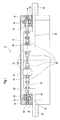
- FIG. 1 shows a schematic, partially sectioned illustration of an exemplary embodiment Embodiment of a shoe roll 10 for the production and / or Treatment of a material web, which is in particular a paper web or cardboard web can act.
- the shoe roll 10 can in particular for be determined a calender and with a particular overhead Heat roller work together.
- the shoe roll 10 has an axially displaceable shell 12, in which it is for example, may be a so-called "laualiflex" coat.
- Sheath 12 is so flexible that it conforms to the shape of a counter or Heat roller can adjust, for example, an extended press nip for smoothing a paper or board web with the heated backing roll too form.
- the shoe roll 10 is a Drive 14 for the rotation of the shell 12 provided.
- this rotary drive 14 configured such that it has a respective axial movement of the Mantle 12 compensates or tolerates.
- clamping discs 16 At its two edges of the jacket 12 is mounted on clamping discs 16. In this case, these clamping disks 16 can be driven via the rotary drive. In addition, the jacket 12 is axially displaceable over the clamping disks 16.
- the clamping discs 16 are driven from the inside. alternative or in addition, however, a drive from the outside is conceivable.
- the rotary drive 14 comprises in the illustrated embodiment both on the leader side as well on the drive side in each case an electric drive motor 18. Except at least an electric drive motor 18, the rotary drive 14, for example also at least one PTO shaft, at least one clutch 20 and / or at least one in particular axially displaceable splined shaft 22 include.
- the drive shafts 24 of the two electric drive motors 18 of the rotary drive 14 can be connected to each other torque-locking.
- the seated on a respective drive shaft 24 electric drive motors 18 may have a disk-like shape.
- the clamping disks 16 each designed as a ring gear Gear 28 provided in which a flying pinion 30 engages.
- the pinions 30 are each mounted in a displaceable carrier.
- a respective one Carrier can on the one hand to a non-rotating part of the respective Clamping device for the jacket 12 attached and on the other hand in one Support body 32 may be performed.
- the pinions 30 each sit on a pinion shaft 34, which is slidable via a spline with a respective, in one Support body 32 mounted intermediate shaft 36 is coupled.
- the intermediate waves 36 are each connected via e.g. a metal bellows coupling 20 with the relevant Drive shaft 24 coupled.
- a respective pinion shaft 34 is fixedly mounted on the bearing sleeve 38, on the also the respective clamping sleeve 16 is mounted.
- bearing pins 40 of the shoe roll 10 can be seen in FIG.
- FIG. 1 The mounting of the clamping disks 16 and the pinion shafts 34 is shown in FIG. 1 with "60” or "62" indicated.
- FIG. 2 shows a modification of the embodiment according to FIG between a respective pinion shaft 34 and the respective drive shaft 24 a preferably double universal joint 42 is provided.
- Such Cardan joint 42 is used to compensate for any wobbling movements the clamping or end disks 16.
- the embodiment according to Figure 2 at least substantially the same structure as the of Figure 1 have. Mutually corresponding parts are the same reference numerals assigned.
- FIG. 3 shows a partial representation of a shoe roll comparable to FIG 10 with a crowned toothing between pinion 30 and gear 28th
- Teeth 44 of the pinion 30 in section through the axial center of the pinion 30th (Section B-B-) has a greater thickness than in the axially outer region (section A-A).
- Such spherical toothing is particularly advantageous if the Angle between the respective pinion shaft 34 and the roller axis unequal Is zero.
- FIG. 4 shows a shoe cross-section 10 in a schematic cross-sectional view with a be pressed against the roll shell 12 ⁇ labstreifance 46.
- a Such ⁇ labstreifology 46 may in the circumferential direction in particular before and / or behind a press shoe 50, preferably in at least one upper quadrant of the roller, be provided. She is with the nip open with a counter roll such as e.g. a heating roller is formed, to the jacket 12 can be pressed.
- a counter roll such as e.g. a heating roller is formed
- an oil collecting trough 48 can also be provided or -rinne be provided, in which the stripped oil by gravity passes and over which this oil is traceable into the cooling oil circuit.
- the support body 32 and a bearing journal 40 are again the roller 10 to recognize.
- the applicable to the inside of the jacket 12 ⁇ labstreifance 46 is radially movable in the present case, for example. Between this ⁇ labstreifance 46 and the oil pan 48 can Be provided baffle 52 for the stripped oil.
- Figure 5 shows a schematic representation of a cooled electrical Drive motor 18, in whose stator an air pressure p1 prevails, wherein this pressure is preferably slightly higher than the internal cylinder pressure p0.
- the Sealing can for example via a shaft seal 54 or the like respectively.
- a drive is intended, inter alia, to drive the clamping disks, wherein a Drive from the outside and / or from the inside is possible.
- the roll shell axially displaced to counteract premature wear.
- the drive must be axially adjustable, including except an electrical Drive motor on the driver side and the drive side, for example, at least a PTO, at least one clutch and / or at least one Splined shaft can be provided.
- the provided on the driver and drive side Drive shafts can be connected with each other torque-locking be. Basically is through appropriate sensors and a corresponding Control but also a master / slave operation of the engine conceivable. With the Use of two motors ensures the required redundancy.
- the motors can be provided with a cooling, the cooling for example by a fluid, gas (air), water and preferably oil takes place, as in a respective leakage oil in the jacket is not contaminated.
- a cooling for example by a fluid, gas (air), water and preferably oil takes place, as in a respective leakage oil in the jacket is not contaminated.
- the position of the teeth of the internally toothed ring gear should be relative to the Do not change the teeth of the pinion as much as possible to avoid wear or tear Damage to the teeth should be avoided.
- a possible cause for each one Positional change are wobbling movements of the clamping discs and / or a respective deflection of the pinion shafts.
- the shoe whales can be provided with a so-called inner hub.
- the nip By lifting or lowering the press shoe, the nip can therefore be opened or closed.
- the lubricating oil of the jacket becomes However, no longer reliably stripped off, which can lead to damage.
- the oil scraper is pressable and is created with the nip open. The stripped oil runs due to gravity in an oil sump and is there again in the Cooling oil circuit fed back (see Figure 4).
- the paper web is between an overhead heating roller and the bottom Shoe roll performed with rotating press cover.
- the Shoe roll can be displaced hydraulically in the vertical direction.
- the Heating roller is preferably installed stationary. For generating a pressing pressure the shoe roll is first turned against the heating roller.
- either the shoe roll is raised until the heating roller and just touch the coat of the shoe roll, or the shoe roll is raised until the outer diameter of the heating roller and the undeformed Mantels overlap.
- the mantle dips into the outside diameter the heating roller and is deformed.
- the Pressure shoe height with shims screwed to the shoe underside each be adapted.
- the necessary pressing pressure is achieved by, for example, hydraulic pressure elements applied, which press the shoe against the heating roller.
- These pressing elements for example, in two rows perpendicular to Paper direction be arranged. They can be separated with each other Pressure are applied. By different pressures in the two Rows can then be the driving point of the resulting compressive force in the paper direction be moved. Resulting from such a shift a change of the pressure profile in the paper direction.
- the pressure in the both rows can be varied by, for example, ⁇ 25%.
- At the paper web edge on the leader and the drive side can at least the in each case four outermost pressing elements individually with different pressures be charged.
- the shoe roll can be used with pressure shoes with a press zone length between For example, be equipped 130 mm and 250 mm, for example.
- the pressure shoe without a removal of Shoe roll to be changed.
- the shoe roll for example about 300 mm away from the heating roller.
- the press cover must not come in direct contact with the heating roller, since the jacket material can not withstand the surface temperature of the heating roller would. Therefore, the press gap may only be closed when a Paper web is located in the press nip.
- the edge area at fluctuating Width of the paper web to a contact between the heating roller and press cover to can prevent, here with a paper speed revolving Teflon tape or the like whose position is via a web edge sensor and an adjustable support frame of the paper web edge readjusted becomes.
- the press cover in the edge region with a water / air mixture be cooled.
- the drive required for this purpose is preferably located in the interior of the shoe roll.
- This gear is preferably designed as a ring gear, in which engages a cantilevered pinion.
- the pinion is mounted on the and the drive side in each case mounted in a displaceable carrier, on the one hand on a non-rotating part of the respective clamping device for the Fixed press cover and on the other hand guided in the support body.
- the pinion shafts can on the driver and the drive side each have a spline displaceable with one each on the driver or drive side in the Be coupled support body mounted intermediate shaft.
- the intermediate shafts can each with one on the leader or drive side existing metal bellows coupling coupled to the two drive shafts be.
- On each of these two drive shafts is expediently a disc-shaped Electric motor attached.
- the two drive shafts can over a propeller shaft with e.g. Metal bellows couplings mechanically with each other be connected.
- the two clamping disks which are the Record rotating press jacket, mechanically interconnected.
- the Both electric motors are preferably internally cooled with oil. All Electric lines can be through the bearing pin on the drive side be led out of a roller. All shaft bearings and the gears on the driver and drive side can each have one nozzle per lubrication point Be supplied with pressure oil.
- an external Drive can be retrofitted, on the drive side via a shaft through a bearing block and a clamping device in the gear of the clamping disc intervenes.
Landscapes
- Paper (AREA)
- Friction Gearing (AREA)
- Manufacturing And Processing Devices For Dough (AREA)
- Reduction Rolling/Reduction Stand/Operation Of Reduction Machine (AREA)
- Treatment Of Fiber Materials (AREA)
Abstract
Description
Diese Aufgabe wird erfindungsgemäß dadurch gelöst, dass der Rotationsantrieb so ausgestaltet ist, dass er eine jeweilige axiale Bewegung des Mantels ausgleicht oder toleriert.
- Figur 1
- eine schematische, teilweise geschnittene Darstellung einer beispielhaften Ausführungsform einer Schuhwalze,
- Figur 2
- eine Abwandlung der Ausführungsform gemäß Figur 1 mit einem doppelten Kardangelenk zwischen einer jeweiligen Ritzelwelle und einer jeweiligen Antriebswelle,
- Figur 3
- eine mit der Figur 1 vergleichbare Darstellung einer Schuhwalze mit einer balligen Verzahnung zwischen Zahnrad und Ritzel,
- Figur 4
- eine schematische Querschnittsdarstellung einer Schuhwalze mit einer an den Walzenmantel anpressbaren Ölabstreifleiste und
- Figur 5
- eine schematische Darstellung eines gekühlten elektrischen Antriebsmotors.
- verschiedene Achsabstände zwischen Schuhwalze und Heizwalze durch veränderte Druckschuhhöhe
- variables Druckprofil in Papierlaufrichtung durch ungleiche Anpressdruckverteilung
- variable Anpressdruckverteilung im Randbereich der Papierbahn
- variables Druckprofil durch Einsatz von Druckschuhen mit verschiedenen Presszonenlängen
- schneller Druckschuhwechsel ohne Ausbau der Schuhwalze
- Beschleunigung des Pressmantels durch einen ihm eigenen Antrieb im Innern der Schuhwalze
- Verstellung des angetriebenen Pressmantels in Maschinenquerrichtung zur Vorbeugung von punktuellem Verschleiß
- sichere Ölabfuhr durch pneumatisch anstellbare Abstreifleiste.
- 10
- Schuhwalze
- 12
- Mantel
- 14
- Rotationsantrieb
- 16
- Spannschuh
- 18
- elektrischer Antriebsmotor
- 20
- Kupplung
- 22
- Vielkeilwelle
- 24
- Antriebswelle
- 26
- Gelenkwelle
- 28
- Zahnrad
- 30
- Ritzel
- 32
- Tragkörper
- 34
- Ritzelwelle
- 36
- Zwischenwelle
- 38
- Lagerhülse
- 40
- Lagerzapfen
- 42
- Kardangelenk
- 44
- Zahn
- 46
- Ölabstreifleiste
- 48
- Ölauffangwanne, -rinne
- 50
- Pressschuh
- 52
- Leitblech
- 54
- Abdichtung
- 56
- Einlauf
- 58
- Auslauf
Claims (31)
- Schuhwalze (10) zur Herstellung und/oder Behandlung einer Materialbahn, insbesondere für einen Kalander, mit einem axial versetzbaren Mantel (12) und einem Antrieb (14) für die Rotation des Mantels (12),
dadurch gekennzeichnet, dass der Rotationsantrieb (14) so ausgestaltet ist, dass er eine jeweilige axiale Bewegung des Mantels ausgleicht oder toleriert. - Schuhwalze nach Anspruch 1,
dadurch gekennzeichnet, dass der Mantel (12) an seinen beiden Rändern über Spannscheiben (16) gelagert ist und dass über den Rotationsantrieb die Spannscheiben (16) antreibbar sind. - Schuhwalze nach Anspruch 2,
dadurch gekennzeichnet, dass der Mantel (12) über die Spannscheiben (16) axial versetzbar ist. - Schuhwalze nach einem der vorhergehenden Ansprüche,
dadurch gekennzeichnet, dass der Mantel (12) um etwa ± 50 mm axial versetzbar ist. - Schuhwalze nach einem der vorhergehenden Ansprüche,
dadurch gekennzeichnet, dass die Spannscheiben (16) von außen antreibbar sind. - Schuhwalze nach einem der vorhergehenden Ansprüche,
dadurch gekennzeichnet, dass die Spannscheiben (16) von innen antreibbar sind. - Schuhwalze nach einem der vorhergehenden Ansprüche,
dadurch gekennzeichnet, dass der Rotationsantrieb (14) sowohl auf der Führungsseite als auch auf der Trägerseite jeweils wenigstens einen elektrischen Antriebsmotor (18) umfasst. - Schuhwalze nach einem der vorhergehenden Ansprüche,
dadurch gekennzeichnet, dass der Rotationsantrieb (14) außer wenigstens einem elektrischen Antriebsmotor wenigstens eine Zapfwelle, wenigstens eine Kupplung (20) und/oder wenigstens eine Vielkeilwelle (22) umfassen. - Schuhwalze nach einem der vorhergehenden Ansprüche,
dadurch gekennzeichnet, dass der Rotationsantrieb (14) zumindest zwei elektrische Antriebsmotoren umfasst, deren Antriebswellen (24) drehmomentschlüssig miteinander verbunden sind. - Schuhwalze nach Anspruch 9,
dadurch gekennzeichnet, dass die Antriebswellen (24) über eine Gelenkwelle (26) mit Metallbalgkupplungen mechanisch miteinander verbunden sind. - Schuhwalze nach einem der vorhergehenden Ansprüche,
dadurch gekennzeichnet, dass auf einer jeweiligen Antriebswelle (24) ein jeweiliger scheibenförmiger elektrischer Antriebsmotoren (18) sitzt. - Schuhwalze nach einem der vorhergehenden Ansprüche,
dadurch gekennzeichnet, dass der Rotationsantrieb (14) zumindest zwei elektrische Antriebsmotoren (18) umfasst, die über entsprechende Sensoren und eine entsprechende Regelung nach dem Master/Slave-Prinzip arbeiten. - Schuhwalze nach einem der vorhergehenden Ansprüche,
dadurch gekennzeichnet, dass ein jeweiliger elektrischer Antriebsmotor (18) mit einer Kühlung versehen ist. - Schuhwalze nach Anspruch 13,
dadurch gekennzeichnet, dass der elektrischer Antriebsmotor (18) mit Fluid, Gas bzw. Luft, Wasser und/oder Öl gekühlt ist. - Schuhwalze nach einem der vorhergehenden Ansprüche,
dadurch gekennzeichnet, dass im Walzeninnern an den Spannscheiben (16) jeweils ein als Hohlrad ausgeführtes Zahnrad (28) vorgesehen ist, in das ein fliegendes Ritzel (30) eingreift. - Schuhwalze nach Anspruch 15,
dadurch gekennzeichnet, dass die Ritzel (30) jeweils in einem verschiebbaren Träger gelagert sind. - Schuhwalze nach Anspruch 16,
dadurch gekennzeichnet, dass ein jeweiliger Träger einerseits an einem nicht rotierenden Teil der jeweiligen Spannvorrichtung für den Mantel (12) befestigt und andererseits in einem Tragkörper (32) geführt ist. - Schuhwalze nach einem der vorhergehenden Ansprüche,
dadurch gekennzeichnet, dass die Ritzel (30) jeweils auf einer Ritzelwelle (34) sitzen, die über eine Keilverzahnung verschiebbar mit einer jeweiligen, in einem Tragkörper (32) gelagerten Zwischenwelle (36) gekoppelt ist. - Schuhwalze nach einem der vorhergehenden Ansprüche,
dadurch gekennzeichnet, dass die Zwischenwellen (36) jeweils über eine Metallbalgkupplung (20) mit der betreffenden Antriebswelle (24) gekoppelt sind. - Schuhwalze nach einem der vorhergehenden Ansprüche,
dadurch gekennzeichnet, dass eine jeweilige Ritzelwelle (34) fest auf der Lagerhülse (38) fest gelagert ist, auf der auch die betreffende Spannhülse (16) gelagert ist. - Schuhwalze nach Anspruch 20,
dadurch gekennzeichnet, dass zwischen einer jeweiligen Ritzelwelle (34) und der betreffenden Antriebswelle ein Kardangelenk (42) vorgesehen ist. - Schuhwalze nach einem der vorhergehenden Ansprüche,
gekennzeichnet durch
eine ballige Verzahnung von Ritzel (30) und/oder Zahnrad (28). - Schuhwalze nach einem der vorhergehenden Ansprüche,
dadurch gekennzeichnet, dass im Stator eines jeweiligen elektrischen Antriebsmotors (18) ein Luftüberdruck vorherrscht, wobei dieser Druck vorzugsweise etwas höher als der Walzeninnendruck ist. - Schuhwalze nach einem der vorhergehenden Ansprüche,
dadurch gekennzeichnet, dass der Mantel (12) bezüglich eines feststehenden Tragkörpers (32) der Walze radial verstellbar ist. - Schuhwalze, insbesondere nach einem der vorhergehenden Ansprüche,
dadurch gekennzeichnet, dass in Mantelumlaufrichtung vor und/oder hinter einem Pressschuh (50), vorzugsweise in wenigstens einem oberen Quadranten der Walze, eine Ölabstreifleiste (46) vorgesehen ist. - Schuhwalze nach einem der vorhergehenden Ansprüche,
dadurch gekennzeichnet, dass die Ölabstreifleiste (46) bei mit einem Gegenelement gebildeten geöffneten Nip an den Mantel (12) anpressbar ist. - Schuhwalze nach Anspruch 25 oder 26,
dadurch gekennzeichnet, dass eine Ölauffangwanne (48) vorgesehen ist, in die das abgestreifte Öl schwerkraftbedingt gelangt und über die dieses Öl in den Kühlölkreislauf zurückführbar ist. - Schuhwalze, insbesondere nach einem der vorhergehenden Ansprüche,
dadurch gekennzeichnet, dass zur Einstellung unterschiedlicher radialer Mantelpositionen relativ zu einem feststehenden Tragkörper (32) wenigstens ein den Mantel (12) beaufschlagendes Anpresselement mit einem Unterlegelement versehen ist. - Schuhwalze nach einem der vorhergehenden Ansprüche,
dadurch gekennzeichnet, dass der Mantel (12) über zwei senkrecht zur Mantelumlaufrichtung angeordnete Anpresselementreihen beaufschlagbar ist. - Schuhwalze nach Anspruch 29,
dadurch gekennzeichnet, dass die beiden Anpresselementreihen getrennt voneinander mit Druck beaufschlagbar sind. - Schuhwalze nach einem der vorhergehenden Ansprüche,
dadurch gekennzeichnet, dass auf der Führer- und der Triebseite jeweils zumindest die vier äußersten Anpresselemente einzeln mit verschiedenen Drücken baufschlagbar sind.
Priority Applications (1)
| Application Number | Priority Date | Filing Date | Title |
|---|---|---|---|
| PL05102256T PL1600554T3 (pl) | 2004-05-26 | 2005-03-22 | Walec trzewikowy |
Applications Claiming Priority (2)
| Application Number | Priority Date | Filing Date | Title |
|---|---|---|---|
| DE102004025778 | 2004-05-26 | ||
| DE102004025778A DE102004025778A1 (de) | 2004-05-26 | 2004-05-26 | Schuhwalze |
Publications (3)
| Publication Number | Publication Date |
|---|---|
| EP1600554A2 true EP1600554A2 (de) | 2005-11-30 |
| EP1600554A3 EP1600554A3 (de) | 2005-12-21 |
| EP1600554B1 EP1600554B1 (de) | 2009-06-03 |
Family
ID=34939027
Family Applications (1)
| Application Number | Title | Priority Date | Filing Date |
|---|---|---|---|
| EP05102256A Expired - Lifetime EP1600554B1 (de) | 2004-05-26 | 2005-03-22 | Schuhwalze |
Country Status (4)
| Country | Link |
|---|---|
| EP (1) | EP1600554B1 (de) |
| AT (1) | ATE433010T1 (de) |
| DE (2) | DE102004025778A1 (de) |
| PL (1) | PL1600554T3 (de) |
Families Citing this family (1)
| Publication number | Priority date | Publication date | Assignee | Title |
|---|---|---|---|---|
| DE102009046924A1 (de) | 2009-11-20 | 2011-05-26 | Voith Patent Gmbh | Biegeeinstellwalze |
Family Cites Families (5)
| Publication number | Priority date | Publication date | Assignee | Title |
|---|---|---|---|---|
| DE3607941A1 (de) * | 1985-10-30 | 1987-05-07 | Escher Wyss Gmbh | Presseinrichtung zum entwaessern einer warenbahn |
| SE464922B (sv) * | 1990-05-08 | 1991-07-01 | Valmet Paper Machinery Inc | Pressvals |
| SE9804346D0 (sv) * | 1998-12-16 | 1998-12-16 | Valmet Corp | Method and apparatus for calendering paper |
| SE515926C2 (sv) * | 1999-12-08 | 2001-10-29 | Valmet Karlstad Ab | Metod och anordning för oljeevakuering från en skopressenhet |
| FI116228B (fi) * | 2001-07-05 | 2005-10-14 | Vaahto Oy | Menetelmä pitkänippipuristimen kuormituskengän asennon ohjaamiseksi ja pitkänippipuristin |
-
2004
- 2004-05-26 DE DE102004025778A patent/DE102004025778A1/de not_active Withdrawn
-
2005
- 2005-03-22 DE DE502005007391T patent/DE502005007391D1/de not_active Expired - Lifetime
- 2005-03-22 AT AT05102256T patent/ATE433010T1/de not_active IP Right Cessation
- 2005-03-22 EP EP05102256A patent/EP1600554B1/de not_active Expired - Lifetime
- 2005-03-22 PL PL05102256T patent/PL1600554T3/pl unknown
Also Published As
| Publication number | Publication date |
|---|---|
| PL1600554T3 (pl) | 2009-10-30 |
| ATE433010T1 (de) | 2009-06-15 |
| EP1600554B1 (de) | 2009-06-03 |
| DE502005007391D1 (de) | 2009-07-16 |
| EP1600554A3 (de) | 2005-12-21 |
| DE102004025778A1 (de) | 2005-12-22 |
Similar Documents
| Publication | Publication Date | Title |
|---|---|---|
| EP0008814B1 (de) | Walze mit steuerbarer Durchbiegung, insbesondere für Maschinen zur Erzeugung und Verarbeitung von Bahnen aus Papier oder Kunststoff | |
| AT3330U1 (de) | Verfahren und vorrichtung zum kalandrieren von papier | |
| EP3794244B1 (de) | Doppelkupplungseinheit und antriebsanordnung mit einer solchen doppelkupplungseinheit | |
| EP1075897B1 (de) | Zweischeiben-Feinschleifmaschine | |
| EP0865837B1 (de) | Walzwerksantrieb mit Zahngelenkspindeln und mit einer Vorrichtung zur Umlaufschmierung | |
| DE69901728T2 (de) | Verteilerschurre für schüttgut | |
| DE2929204C2 (de) | ||
| WO2012007097A2 (de) | Vorrichtung zur bearbeitung von bahn- oder bogenförmigem material | |
| DE29902436U1 (de) | Vorrichtung zum Kalandrieren von Papier | |
| EP3108058B1 (de) | Schnellwechselkalander | |
| DE69104482T2 (de) | Durchbiegungssteuerbare walze mit hitzeschwelle. | |
| DE2938580C2 (de) | Durchbiegungssteuerbare Walze | |
| EP1600554B1 (de) | Schuhwalze | |
| EP3356074B1 (de) | Verzahnungsbearbeitungsmaschine mit balg | |
| EP2325386A1 (de) | Biegeeinstellwalze | |
| DE10313444A1 (de) | Vorrichtung, bei der ein erster Zylinder und ein an diesen angestellter zweiter Zylinder einen Spalt bilden | |
| DE102009023741A1 (de) | Drehdurchführung | |
| EP4114572B1 (de) | Faserbehandlungsvorrichtung | |
| DE69506733T2 (de) | Hydrostatische durchbiegungswalze mit selbsttätiger lastregulierung | |
| EP0358790A1 (de) | Mahlvorrichtung | |
| EP3721103B1 (de) | Wälzlageranordnung | |
| CH648914A5 (de) | Keilriemenscheibeneinheit fuer ein keilriemengetriebe mit veraenderlicher uebersetzung. | |
| DE102014200020A1 (de) | Hochgeschwindigkeits-Rotationsdichtung | |
| EP1256730B1 (de) | Biegeeinstellwalzewälzlager | |
| EP2036709B1 (de) | Rundlauf-Tablettenpresse |
Legal Events
| Date | Code | Title | Description |
|---|---|---|---|
| PUAI | Public reference made under article 153(3) epc to a published international application that has entered the european phase |
Free format text: ORIGINAL CODE: 0009012 |
|
| PUAL | Search report despatched |
Free format text: ORIGINAL CODE: 0009013 |
|
| AK | Designated contracting states |
Kind code of ref document: A2 Designated state(s): AT BE BG CH CY CZ DE DK EE ES FI FR GB GR HU IE IS IT LI LT LU MC NL PL PT RO SE SI SK TR |
|
| AX | Request for extension of the european patent |
Extension state: AL BA HR LV MK YU |
|
| AK | Designated contracting states |
Kind code of ref document: A3 Designated state(s): AT BE BG CH CY CZ DE DK EE ES FI FR GB GR HU IE IS IT LI LT LU MC NL PL PT RO SE SI SK TR |
|
| AX | Request for extension of the european patent |
Extension state: AL BA HR LV MK YU |
|
| 16A | New documents despatched to applicant after publication of the search report |
Effective date: 20060119 |
|
| 17P | Request for examination filed |
Effective date: 20060621 |
|
| AKX | Designation fees paid |
Designated state(s): AT BE BG CH CY CZ DE DK EE ES FI FR GB GR HU IE IS IT LI LT LU MC NL PL PT RO SE SI SK TR |
|
| RAP1 | Party data changed (applicant data changed or rights of an application transferred) |
Owner name: VOITH PATENT GMBH |
|
| 17Q | First examination report despatched |
Effective date: 20070702 |
|
| GRAP | Despatch of communication of intention to grant a patent |
Free format text: ORIGINAL CODE: EPIDOSNIGR1 |
|
| GRAS | Grant fee paid |
Free format text: ORIGINAL CODE: EPIDOSNIGR3 |
|
| GRAA | (expected) grant |
Free format text: ORIGINAL CODE: 0009210 |
|
| AK | Designated contracting states |
Kind code of ref document: B1 Designated state(s): AT BE BG CH CY CZ DE DK EE ES FI FR GB GR HU IE IS IT LI LT LU MC NL PL PT RO SE SI SK TR |
|
| REG | Reference to a national code |
Ref country code: GB Ref legal event code: FG4D Free format text: NOT ENGLISH |
|
| REG | Reference to a national code |
Ref country code: CH Ref legal event code: EP |
|
| REG | Reference to a national code |
Ref country code: IE Ref legal event code: FG4D Free format text: LANGUAGE OF EP DOCUMENT: GERMAN |
|
| REF | Corresponds to: |
Ref document number: 502005007391 Country of ref document: DE Date of ref document: 20090716 Kind code of ref document: P |
|
| REG | Reference to a national code |
Ref country code: SE Ref legal event code: TRGR |
|
| PG25 | Lapsed in a contracting state [announced via postgrant information from national office to epo] |
Ref country code: LT Free format text: LAPSE BECAUSE OF FAILURE TO SUBMIT A TRANSLATION OF THE DESCRIPTION OR TO PAY THE FEE WITHIN THE PRESCRIBED TIME-LIMIT Effective date: 20090603 |
|
| REG | Reference to a national code |
Ref country code: PL Ref legal event code: T3 |
|
| NLV1 | Nl: lapsed or annulled due to failure to fulfill the requirements of art. 29p and 29m of the patents act | ||
| PG25 | Lapsed in a contracting state [announced via postgrant information from national office to epo] |
Ref country code: SI Free format text: LAPSE BECAUSE OF FAILURE TO SUBMIT A TRANSLATION OF THE DESCRIPTION OR TO PAY THE FEE WITHIN THE PRESCRIBED TIME-LIMIT Effective date: 20090603 Ref country code: NL Free format text: LAPSE BECAUSE OF FAILURE TO SUBMIT A TRANSLATION OF THE DESCRIPTION OR TO PAY THE FEE WITHIN THE PRESCRIBED TIME-LIMIT Effective date: 20090603 |
|
| REG | Reference to a national code |
Ref country code: IE Ref legal event code: FD4D |
|
| PG25 | Lapsed in a contracting state [announced via postgrant information from national office to epo] |
Ref country code: RO Free format text: LAPSE BECAUSE OF FAILURE TO SUBMIT A TRANSLATION OF THE DESCRIPTION OR TO PAY THE FEE WITHIN THE PRESCRIBED TIME-LIMIT Effective date: 20090603 Ref country code: IE Free format text: LAPSE BECAUSE OF FAILURE TO SUBMIT A TRANSLATION OF THE DESCRIPTION OR TO PAY THE FEE WITHIN THE PRESCRIBED TIME-LIMIT Effective date: 20090603 Ref country code: EE Free format text: LAPSE BECAUSE OF FAILURE TO SUBMIT A TRANSLATION OF THE DESCRIPTION OR TO PAY THE FEE WITHIN THE PRESCRIBED TIME-LIMIT Effective date: 20090603 Ref country code: ES Free format text: LAPSE BECAUSE OF FAILURE TO SUBMIT A TRANSLATION OF THE DESCRIPTION OR TO PAY THE FEE WITHIN THE PRESCRIBED TIME-LIMIT Effective date: 20090914 Ref country code: CZ Free format text: LAPSE BECAUSE OF FAILURE TO SUBMIT A TRANSLATION OF THE DESCRIPTION OR TO PAY THE FEE WITHIN THE PRESCRIBED TIME-LIMIT Effective date: 20090603 Ref country code: IS Free format text: LAPSE BECAUSE OF FAILURE TO SUBMIT A TRANSLATION OF THE DESCRIPTION OR TO PAY THE FEE WITHIN THE PRESCRIBED TIME-LIMIT Effective date: 20091003 |
|
| PG25 | Lapsed in a contracting state [announced via postgrant information from national office to epo] |
Ref country code: SK Free format text: LAPSE BECAUSE OF FAILURE TO SUBMIT A TRANSLATION OF THE DESCRIPTION OR TO PAY THE FEE WITHIN THE PRESCRIBED TIME-LIMIT Effective date: 20090603 |
|
| PG25 | Lapsed in a contracting state [announced via postgrant information from national office to epo] |
Ref country code: PT Free format text: LAPSE BECAUSE OF FAILURE TO SUBMIT A TRANSLATION OF THE DESCRIPTION OR TO PAY THE FEE WITHIN THE PRESCRIBED TIME-LIMIT Effective date: 20091003 Ref country code: BG Free format text: LAPSE BECAUSE OF FAILURE TO SUBMIT A TRANSLATION OF THE DESCRIPTION OR TO PAY THE FEE WITHIN THE PRESCRIBED TIME-LIMIT Effective date: 20090903 |
|
| PLBE | No opposition filed within time limit |
Free format text: ORIGINAL CODE: 0009261 |
|
| STAA | Information on the status of an ep patent application or granted ep patent |
Free format text: STATUS: NO OPPOSITION FILED WITHIN TIME LIMIT |
|
| PG25 | Lapsed in a contracting state [announced via postgrant information from national office to epo] |
Ref country code: DK Free format text: LAPSE BECAUSE OF FAILURE TO SUBMIT A TRANSLATION OF THE DESCRIPTION OR TO PAY THE FEE WITHIN THE PRESCRIBED TIME-LIMIT Effective date: 20090603 |
|
| 26N | No opposition filed |
Effective date: 20100304 |
|
| PGFP | Annual fee paid to national office [announced via postgrant information from national office to epo] |
Ref country code: AT Payment date: 20100311 Year of fee payment: 6 |
|
| BERE | Be: lapsed |
Owner name: VOITH PATENT G.M.B.H. Effective date: 20100331 |
|
| PG25 | Lapsed in a contracting state [announced via postgrant information from national office to epo] |
Ref country code: MC Free format text: LAPSE BECAUSE OF NON-PAYMENT OF DUE FEES Effective date: 20100331 Ref country code: GR Free format text: LAPSE BECAUSE OF FAILURE TO SUBMIT A TRANSLATION OF THE DESCRIPTION OR TO PAY THE FEE WITHIN THE PRESCRIBED TIME-LIMIT Effective date: 20090904 |
|
| REG | Reference to a national code |
Ref country code: CH Ref legal event code: PL |
|
| GBPC | Gb: european patent ceased through non-payment of renewal fee |
Effective date: 20100322 |
|
| PG25 | Lapsed in a contracting state [announced via postgrant information from national office to epo] |
Ref country code: BE Free format text: LAPSE BECAUSE OF NON-PAYMENT OF DUE FEES Effective date: 20100331 Ref country code: CH Free format text: LAPSE BECAUSE OF NON-PAYMENT OF DUE FEES Effective date: 20100331 Ref country code: LI Free format text: LAPSE BECAUSE OF NON-PAYMENT OF DUE FEES Effective date: 20100331 |
|
| PG25 | Lapsed in a contracting state [announced via postgrant information from national office to epo] |
Ref country code: GB Free format text: LAPSE BECAUSE OF NON-PAYMENT OF DUE FEES Effective date: 20100322 |
|
| PGFP | Annual fee paid to national office [announced via postgrant information from national office to epo] |
Ref country code: FR Payment date: 20110404 Year of fee payment: 7 Ref country code: PL Payment date: 20110223 Year of fee payment: 7 Ref country code: SE Payment date: 20110314 Year of fee payment: 7 |
|
| PG25 | Lapsed in a contracting state [announced via postgrant information from national office to epo] |
Ref country code: AT Free format text: LAPSE BECAUSE OF NON-PAYMENT OF DUE FEES Effective date: 20110322 |
|
| PGFP | Annual fee paid to national office [announced via postgrant information from national office to epo] |
Ref country code: IT Payment date: 20120327 Year of fee payment: 8 |
|
| PG25 | Lapsed in a contracting state [announced via postgrant information from national office to epo] |
Ref country code: CY Free format text: LAPSE BECAUSE OF FAILURE TO SUBMIT A TRANSLATION OF THE DESCRIPTION OR TO PAY THE FEE WITHIN THE PRESCRIBED TIME-LIMIT Effective date: 20090603 |
|
| PG25 | Lapsed in a contracting state [announced via postgrant information from national office to epo] |
Ref country code: LU Free format text: LAPSE BECAUSE OF NON-PAYMENT OF DUE FEES Effective date: 20100322 Ref country code: HU Free format text: LAPSE BECAUSE OF FAILURE TO SUBMIT A TRANSLATION OF THE DESCRIPTION OR TO PAY THE FEE WITHIN THE PRESCRIBED TIME-LIMIT Effective date: 20091204 |
|
| REG | Reference to a national code |
Ref country code: SE Ref legal event code: EUG |
|
| PG25 | Lapsed in a contracting state [announced via postgrant information from national office to epo] |
Ref country code: SE Free format text: LAPSE BECAUSE OF NON-PAYMENT OF DUE FEES Effective date: 20120323 Ref country code: TR Free format text: LAPSE BECAUSE OF FAILURE TO SUBMIT A TRANSLATION OF THE DESCRIPTION OR TO PAY THE FEE WITHIN THE PRESCRIBED TIME-LIMIT Effective date: 20090603 |
|
| REG | Reference to a national code |
Ref country code: FR Ref legal event code: ST Effective date: 20121130 |
|
| PG25 | Lapsed in a contracting state [announced via postgrant information from national office to epo] |
Ref country code: FR Free format text: LAPSE BECAUSE OF NON-PAYMENT OF DUE FEES Effective date: 20120402 |
|
| PGFP | Annual fee paid to national office [announced via postgrant information from national office to epo] |
Ref country code: DE Payment date: 20130321 Year of fee payment: 9 Ref country code: FI Payment date: 20130313 Year of fee payment: 9 |
|
| PG25 | Lapsed in a contracting state [announced via postgrant information from national office to epo] |
Ref country code: PL Free format text: LAPSE BECAUSE OF NON-PAYMENT OF DUE FEES Effective date: 20120322 |
|
| REG | Reference to a national code |
Ref country code: PL Ref legal event code: LAPE |
|
| REG | Reference to a national code |
Ref country code: DE Ref legal event code: R119 Ref document number: 502005007391 Country of ref document: DE |
|
| PG25 | Lapsed in a contracting state [announced via postgrant information from national office to epo] |
Ref country code: FI Free format text: LAPSE BECAUSE OF NON-PAYMENT OF DUE FEES Effective date: 20140322 |
|
| REG | Reference to a national code |
Ref country code: DE Ref legal event code: R119 Ref document number: 502005007391 Country of ref document: DE Effective date: 20141001 |
|
| PG25 | Lapsed in a contracting state [announced via postgrant information from national office to epo] |
Ref country code: DE Free format text: LAPSE BECAUSE OF NON-PAYMENT OF DUE FEES Effective date: 20141001 |
|
| PG25 | Lapsed in a contracting state [announced via postgrant information from national office to epo] |
Ref country code: IT Free format text: LAPSE BECAUSE OF NON-PAYMENT OF DUE FEES Effective date: 20140322 |