EP1600354A2 - Beheizbares Furnierelement für Kfz-Lenkräder und Verfahren zur Herstellung eines solchen Furnierelementes - Google Patents
Beheizbares Furnierelement für Kfz-Lenkräder und Verfahren zur Herstellung eines solchen Furnierelementes Download PDFInfo
- Publication number
- EP1600354A2 EP1600354A2 EP05090149A EP05090149A EP1600354A2 EP 1600354 A2 EP1600354 A2 EP 1600354A2 EP 05090149 A EP05090149 A EP 05090149A EP 05090149 A EP05090149 A EP 05090149A EP 1600354 A2 EP1600354 A2 EP 1600354A2
- Authority
- EP
- European Patent Office
- Prior art keywords
- veneer
- piece
- layer
- covering
- heating element
- Prior art date
- Legal status (The legal status is an assumption and is not a legal conclusion. Google has not performed a legal analysis and makes no representation as to the accuracy of the status listed.)
- Granted
Links
Images





Classifications
-
- B—PERFORMING OPERATIONS; TRANSPORTING
- B62—LAND VEHICLES FOR TRAVELLING OTHERWISE THAN ON RAILS
- B62D—MOTOR VEHICLES; TRAILERS
- B62D1/00—Steering controls, i.e. means for initiating a change of direction of the vehicle
- B62D1/02—Steering controls, i.e. means for initiating a change of direction of the vehicle vehicle-mounted
- B62D1/04—Hand wheels
- B62D1/06—Rims, e.g. with heating means; Rim covers
-
- B—PERFORMING OPERATIONS; TRANSPORTING
- B62—LAND VEHICLES FOR TRAVELLING OTHERWISE THAN ON RAILS
- B62D—MOTOR VEHICLES; TRAILERS
- B62D1/00—Steering controls, i.e. means for initiating a change of direction of the vehicle
- B62D1/02—Steering controls, i.e. means for initiating a change of direction of the vehicle vehicle-mounted
- B62D1/04—Hand wheels
- B62D1/06—Rims, e.g. with heating means; Rim covers
- B62D1/065—Steering wheels with heating and ventilating means
-
- Y—GENERAL TAGGING OF NEW TECHNOLOGICAL DEVELOPMENTS; GENERAL TAGGING OF CROSS-SECTIONAL TECHNOLOGIES SPANNING OVER SEVERAL SECTIONS OF THE IPC; TECHNICAL SUBJECTS COVERED BY FORMER USPC CROSS-REFERENCE ART COLLECTIONS [XRACs] AND DIGESTS
- Y10—TECHNICAL SUBJECTS COVERED BY FORMER USPC
- Y10T—TECHNICAL SUBJECTS COVERED BY FORMER US CLASSIFICATION
- Y10T156/00—Adhesive bonding and miscellaneous chemical manufacture
- Y10T156/10—Methods of surface bonding and/or assembly therefor
- Y10T156/1002—Methods of surface bonding and/or assembly therefor with permanent bending or reshaping or surface deformation of self sustaining lamina
-
- Y—GENERAL TAGGING OF NEW TECHNOLOGICAL DEVELOPMENTS; GENERAL TAGGING OF CROSS-SECTIONAL TECHNOLOGIES SPANNING OVER SEVERAL SECTIONS OF THE IPC; TECHNICAL SUBJECTS COVERED BY FORMER USPC CROSS-REFERENCE ART COLLECTIONS [XRACs] AND DIGESTS
- Y10—TECHNICAL SUBJECTS COVERED BY FORMER USPC
- Y10T—TECHNICAL SUBJECTS COVERED BY FORMER US CLASSIFICATION
- Y10T156/00—Adhesive bonding and miscellaneous chemical manufacture
- Y10T156/10—Methods of surface bonding and/or assembly therefor
- Y10T156/1002—Methods of surface bonding and/or assembly therefor with permanent bending or reshaping or surface deformation of self sustaining lamina
- Y10T156/1043—Subsequent to assembly
Definitions
- the invention relates to a heatable veneer element for Motor vehicle steering wheels according to the preamble of claim 1. Further The invention relates to a method for producing a such veneer element.
- Such heatable veneer elements are used in particular for partially enclosing a motor vehicle steering wheel rim.
- These Veneer elements have a cover veneer piece with at least a layer of wood and / or imitation wood and a inseparably connected to the cover veneer heating element for heating the covering veneer piece.
- the present invention thus has the task Basically, a heatable veneer element for car steering wheels to provide that the above Overcomes difficulties and a procedure provide so that such a veneer element economically and with technically acceptable means can be produced.
- the covering veneer piece directly and inseparably connected to the heating element is.
- construction of the veneer means that between the heating element generating the heating and the at least one layer of wood or imitation wood the cover veneer element has no further layer, the heat generated on the way to the steering wheel rim surface must be penetrated.
- the feature "Imitation wood” is understood here as including that too other materials than wood, in particular plastic, fall whose outer optical appearance in the form of a Wood grain appears.
- the above-defined direct connection has the Advantage that the path to be covered by the heat minimizes and thus a short heating time ( ⁇ 3 min) of the Steering wheel rim can be realized.
- the to be laid back Way corresponds essentially to the strength of Cover veneer whose one or more layers each very thin, i. ⁇ 1 mm per layer, can be formed.
- the heating element a heating layer on and is on his the cover veneer piece opposite side inseparable with a carrier piece connected.
- the carrier piece serves the mechanical Stabilization and as a fastener of the thin Laminate, formed from covering veneer piece and heating element, on the steering wheel rim.
- the Heating element at least one adjacent to the support piece lower blind veneer layer on. That's the way it will be in particular, allows thin on the blind veneer Pre-fixed heating layers in a simple manner in the To be able to process production of the veneer element.
- the support piece preferably has a plastic and / or wood existing mounting means for mounting the Veneer element on a car steering wheel.
- the mounting means are used in particular for producing a clamping, snap, Latch or welded joint of veneer element and Steering wheel rim.
- a preferred variant of the invention that is Cover veneer two-layered. It insists on his the heating element facing away from a Cover veneer layer and immediately adjacent to it one inseparably associated with the top veneer layer upper blind veneer layer.
- the use of a suitable Blind veneers allows the lamination of the aesthetically pleasing top veneer layer under ideal Adhesion properties.
- heating element comparable good adhesion properties for the covering veneer layer, it will Covering piece preferred from a single decorative Cover veneer layer exist.
- the top veneer layer is on its outward facing Side preferably with a thin, i. ⁇ 1 mm thick, Cover lacquer layer provided.
- the heating layer of the heating element can be varied Way in particular as Bankgewirke, heating fabric, heating foil or as fleece, each with printed or embedded train electrical heating conductors.
- a fleece Can be made of polyamide, polyester, polypropylene, sisal, cellulose or be formed from mixtures of these materials.
- the changes Resistance of the electrical conductors and / or their spatial distance depending on the location of the Tracks on the heating layer This can be done defined areas with different speeds Realize heating times.
- the veneer element has a cup-shaped Structure such that the steering wheel rim of a motor vehicle steering wheel engage in sections through the veneer element leaves.
- the veneer elements are in the form of Veneer shells formed such that the steering wheel rim of at least two juxtaposed veneer shells is completely lockable.
- the veneer element mechanical fasteners on when joining several veneer elements around a section of the Steering wheel rim interact in such a way that the one another abutting edges of the veneer as smooth as possible Make transition.
- Such mechanical connection means can be used in particular as tongue and groove elements form along the abutting edges of the Veneer elements are arranged.
- veneer elements in the form of half-shells, such that two veneer elements the steering wheel rim along its half-cross-sectional circumference embrace symmetrically.
- the present invention also relates to a method for Production of a veneer element with the following Steps. First, a tailored Cover veneer consisting of at least one layer Wood and / or imitation wood provided. After that will be Adhesive on one side of the provided Cover veneer piece and / or on one side of the heating element intended. Subsequently, the heating element on the Cover veneer laid on and finally an inseparable Connection between cover veneer and heating element produced.
- a second variant of the production method provides that both the cover veneer and the heating element after the step of providing adhesives each separately a deformation step for the preparation be subjected to permanent deformation. Only in the This is followed by the process step of Making an inseparable connection between Cover veneer and heating element.
- a third variant of the production process provides that both the cover veneer and the heating element before the step of providing adhesives each separately a deformation step for the preparation be subjected to permanent deformation. After that then the adhesives are provided and subsequently This is followed by the process step of producing a inseparable connection between covering veneer piece and Heating element.
- the heating element is preferably inseparable from a Blind veneer layer and / or a support piece connected. This also allows very thin heating elements with as well thin cover veneer pieces in a simple way to process.
- the covering veneer as Inseparable laminate of a veneer layer and a upper blind veneer layer is provided.
- the veneer element after the process step of Production of an inseparable connection on one Carrier piece attached in a further process step is the veneer element after the process step of Production of an inseparable connection on one Carrier piece attached in a further process step.
- the veneer element after the process step for producing the inseparable Compound is injected with a plastic, and characterized a carrier piece is formed. In this way can be particularly cost-effective veneer elements produce.
- the adhesives applied to the top veneer piece are in all the above-mentioned process variants preferred as Glue paper or formed as applied glue layer.
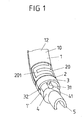
- FIG. 1 shows the perspective view of a Steering wheel rim section with two half-shell shaped veneer elements according to the invention.
- the two Veneer elements surround the steering wheel rim its diameter completely.
- the outermost layer of the Both veneer elements will each be replaced by a Covering piece 1, 1 'with at least one layer Wood or wood imitation formed.
- Each cover veneer piece 1, 1 ' includes a very outside and therefore visibly arranged Cover veneer layer 10 of a visually appealing wood or imitation wood. This gives the steering wheel rim of the Car steering wheel the visual appearance of a wood steering wheel.
- the steering wheel rim skeleton 5 is with a Cover made of foam plastic 4, preferably made of polyurethane or made of expandable polypropylene.
- This Foamed plastic 4 is used in a known manner to kinetic Impact energy of the motor vehicle driver in the event of a crash by To absorb deformation.
- the steering wheel rim skeleton 5 and the This surrounding foam plastic 4 thus form the Base steering wheel rim.
- this Basis steering wheel rim can, as shown in Figure 1, Holding structures 41 are formed, with the corresponding Mounting means 31 of the Basislenkradkranz enclosing Veneer elements cooperate to form the veneer elements Fix the steering wheel rim.
- FIG 1 is due to the perspective view only the upper circumferential groove 41 for fixing the upper Veneer element recognizable.
- Either the lower one Holding structure 41 is substantially mirror-symmetrical in the same groove shape or it is another form the support structures 41 for the lower veneer element intended. In the latter variant, it is possible by the different design of the support structures 41 the spatial allocation of the individual veneer elements along the steering wheel rim. When mounting the Veneers will in this way their mounting on a faulty position along the steering wheel rim avoided.
- the mounting means 31 are integral with the support piece. 3 formed of the veneer element.
- the one-piece training is particularly easy to realize that the Support piece 3 in the form of a plastic injection molded part is provided.
- the preformed and laminated unit of Covering piece 1 and heating element 2 can be directly for forming the carrier piece 3 with plastic back-mold.
- a support piece. 3 made of wood and the preformed and laminated Unit of cover veneer 1 and heating element 2 thereon mount or cover veneer piece 1, heating element 2 and Carrier piece 3 to be laminated in one operation.
- the planar heating element 2 with a meandering electrical heating conductor 201 recognizable.
- This heating element 2 can be, for example with a heating layer 20 of a film or a nonwoven form, on which the electrical heating conductors 201 in the desired geometry are printed.
- the Heating element 2 is used with its heating layer 20 for heating the above arranged from at least one wood and / or Imitation wood veneer existing cover veneer 1.
- the Covering piece 1 has an externally visible arranged Cover veneer layer 10, which is the optical-aesthetic Determined "wood impression" of the steering wheel rim.
- These Cover veneer layer 10 is of a thin, usually transparent topcoat layer 12 coated.
- These Topcoat layer 12 is typically thin, i. with a Thickness ⁇ 1 mm formed. Especially if the Heat conduction properties of the topcoat are good however, it is also conceivable that the topcoat layer 12 is stronger than 1 mm train.
- FIGS. 2a to 2d show various embodiments of the invention, a covering veneer piece 1, a Heating element 2 and a support piece 3 include Veneer element in detail.
- FIG. 2a In the first embodiment shown in Figure 2a is the Heating layer 20 of the heating element 2 symmetrically from a lower blind veneer layer 21 and an upper one Blank veneer layer 11 surrounded.
- the terms “bottom” and “above” always refer to the following Orientation that "above” the outer, visible Cover veneer layer 10 is arranged.
- the in Figure 2a Symmetric design shown ensures that when Establishing an inseparable connection between Heating element 2 and veneer piece 1, which is usually with whose deformation is associated with a shell-like shape, a mechanical warping of the laminated in this way Veneer shell is prevented.
- Figure 2c is another "asymmetric" layer structure shown. In this embodiment, this includes Heating element 2 only the heating layer 20, without being on the the cover veneer piece 1 side facing away from a lower Blind veneer connects. Otherwise, the in Figure 2c structure shown in Figure 2a.
- FIG. 2d shows a further embodiment of the invention Veneer element with a symmetrical layer structure.
- the covering veneer 1 from a single Covering veneer layer 10 and the heating element 2 from a single heating layer 20 consists.
- the top veneer layer 10 has a its top side disposed topcoat layer 12.
- These Topcoat layer 12 is usually less than 1 mm thick.
- toppings and blind veneer layers it is common to use both toppings and blind veneer layers to be used with a thickness of approx. 0.6 mm.
- the heating layer 20 a color matched to the cover veneer 1 color has, in this simple way, the optical Appearance of the veneer layer 10 due to the adapted Coloring not significantly disturbed. The resulting cracks even when varnishing the top veneer layer 10 by the topcoat 12 filled so that the feel of the Cover veneer layer 10 despite existing cracks not is impaired.
- FIG. 3 shows by way of example the top view of a heating layer 20 with electrical heating conductors 201.
- the heating layer 20 can be made of a suitable fleece or form from a film, wherein the electrical Schuleiterbahnen 201 in the desired geometry on the Heating layer 20 are printed. It is also conceivable that the Schuleiterbahnen 201 surrounded by nonwoven layers embedded are arranged.
- the printed conductors 201 are in certain areas take a smaller spatial distance from each other, ensures that the heating time of the Cover veneer piece 1 is particularly short in these areas.
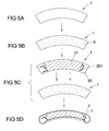
- FIGS. 4a to 4d and 5a to 5d two process variants for the preparation of the inventive Veneer elements described.
- a Covering piece 1 provided in the first process step of Figure 4a.
- This cover veneer 1 consists for example of a single one Cover veneer layer 10 (see Figure 2b) or a laminate a cover veneer layer 10 with a blind veneer layer 11 (see Figure 2a).
- Process step will be a surface of the provided Cover veneer piece 1 and / or the non-visible underside of the heating element shown in Figure 4c with a Adhesive K provided.
- This adhesive K will usually in the form of a liquid applied glue or a suitably sized glue paper used.
- FIG. 4 c shows the lamination of the covering veneer piece 1 the heating element 2, creating an inseparable connection is realized.
- the heating element 2 comprises in this Embodiment of the manufacturing process exclusively a heating layer 20 with thereon arranged electrical Heating conductor tracks 201 (see Figure 2c or 2d).
- the in Figure 4c illustrated process step of manufacturing an inseparable connection (lamination) between Covering piece 1 and heating element 2 goes to this first Variant of the manufacturing process associated with a permanent deformation of this laminate to produce a cupped veneer element.
- the result of this Method step is shown by way of example in Figure 4d.
- FIGS. 6a to 6d show a second variant of the invention inventive production process. That in the Figures 6a and 6b shown providing the Cover veneer piece 1 and the heating element 2 and des Provision of adhesives K corresponds to the above described method steps of Figures 4a and 4b. in the Difference to the first manufacturing process, are still before making the inseparable connection the Covering piece 1 and the heating element 2 each separately a deformation step to produce a permanent Subjected to deformation. This is schematically in FIG. 6c shown. Subsequently, only cover veneer piece 1 and Heating element 2 laminated. The result shown in Figure 6d corresponds to the process result shown in FIG. 4d.
- FIGS. 7a to 7d corresponds to that of Figures 6a to 6d, wherein the only Difference is that a heating element 2 with a Blind veneer layer 21 is used. That in Figure 7d shown process product corresponds to that of Figure 5d.
- FIGS. 8a to 8d show a third variant of the invention inventive production process. That in the Figure 8a shown providing the cover veneer piece 1 and of the heating element 2 corresponds to the previously described Process step of Figures 4a and 6a. In contrast to second manufacturing process, but will be before the Process step of providing adhesives K das Covering piece 1 and the heating element 2 each separately a deformation step to produce a permanent Subjected to deformation. This is schematically in FIG. 8b shown. Subsequently, veneer piece 1 and / or Heating element 2 provided with adhesive K (Fig. 8c) and finally laminated (Figure 8c). The shown in Figure 8d Result corresponds to that shown in Figure 4d or 6d Method result.
- FIG. 9a to 9d corresponds to that of the figures 8a to 8d, wherein the only Difference is that a heating element 2 with a Blind veneer layer 21 is used. That in FIG. 9d shown process product corresponds to that of Figure 7d or FIG. 5d.
Landscapes
- Engineering & Computer Science (AREA)
- Chemical & Material Sciences (AREA)
- Combustion & Propulsion (AREA)
- Transportation (AREA)
- Mechanical Engineering (AREA)
- Steering Controls (AREA)
Abstract
Description
- Fig. 1 -
- einen schematischen Schichtaufbau eines Lenkradkranz-Abschnittes mit einem erfindungsgemäßen Furnierstück in einer perspektivischen Ansicht;
- Fig. 2a -
- eine Querschnittansicht des schematischen Schichtaufbaus einer ersten Ausführungsform des erfindungsgemäßen Furnierstücks;
- Fig. 2b -
- eine Querschnittansicht gemäß Figur 2a einer zweiten Ausführungsform;
- Fig. 2c -
- eine Querschnittsansicht einer dritten Ausführungs-form;
- Fig. 2d -
- eine Querschnittsansicht einer vierten Ausführungsform;
- Fig. 3 -
- eine Aufsicht eines Heizelementes mit aufgedruckten elektrischen Heizleiterbahnen;
- Fig. 4a-4d -
- eine schematische Darstellung der Verfahrensschritte eines ersten Furnierelement-Herstellungsverfahrens;
- Fig. 5a-5d -
- ein Verfahren gemäß Fig. 4a-4d, wobei ein abgewandeltes Heizelement eingesetzt wird;
- Fig. 6a-6d -
- eine schematische Darstellung der Verfahrensschritte eines zweiten Furnierelement-Herstellungsverfahrens;
- Fig. 7a-7d -
- ein Verfahren gemäß Fig. 6a-6d, wobei ein abgewandeltes Heizelement eingesetzt wird;
- Fig. 8a-8d -
- eine schematische Darstellung der Verfahrensschritte eines dritten Furnierelement-Herstellungsverfahrens und
- Fig. 9a-9d -
- ein Verfahren gemäß Fig. 8a-8d, wobei ein abgewandeltes Heizelement eingesetzt wird.
- 1
- Deckfurnierstück
- 10
- Deckfurnierschicht
- 11
- Obere Blindfurnierschicht
- 12
- Decklackschicht
- 2
- Heizelement
- 20
- Heizschicht
- 201
- Elektrische Heizleiterbahnen
- 21
- Untere Blindfurnierschicht
- 3
- Trägerstück
- 31
- Montagemittel
- 32
- Mechanische Verbindungsmittel
- 4
- Schaummantel
- 41
- Haltestrukturen
- 5
- Lenkradskelett
Claims (25)
- Beheizbares Furnierelement für Kfz-Lenkräder umfassend:dadurch gekennzeichnet, dass das Deckfurnierstück (1) unmittelbar und untrennbar mit dem Heizelement (2) verbunden ist.ein Deckfurnierstück (1) mit mindestens einer Schicht aus Holz- und/oder Holzimitat undein untrennbar mit dem Deckfurnierstück (1) verbundenes Heizelement (2) zur Beheizung des Deckfurnierstückes (1),
- Furnierelement gemäß Anspruch 1, dadurch gekennzeichnet, dass das Heizelement (2) eine Heizschicht (20) umfasst und auf seiner dem Deckfurnierstück (1) abgewandten Seite untrennbar mit einem Trägerstück (3) verbunden ist.
- Furnierelement gemäß Anspruch 2, dadurch gekennzeichnet, dass das Heizelement (2) mindestens eine an das Trägerstück (3) angrenzende untere Blindfurnierschicht (21) aufweist.
- Furnierelement gemäß Anspruch 2 oder 3, dadurch gekennzeichnet, dass das Trägerstück (3) ein aus Kunststoff und/oder Holz bestehendes Montagemittel (31) zur Montage des Furnierelements auf einem Kfz-Lenkrad aufweist.
- Furnierelement gemäß einem der Ansprüche 1 bis 4, dadurch gekennzeichnet, dass das Heizelement (2) eine dem Deckfurnierstück (1) angepasste Farbgebung aufweist.
- Furnierelement gemäß einem der Ansprüche 1 bis 5, dadurch gekennzeichnet, dass das Deckfurnierstück (1) auf seiner dem Heizelement (2) abgewandten Seite eine Deckfurnierschicht (10) und auf seiner anderen Seite ein mit der Deckfurnierschicht (10) untrennbar verbundene obere Blindfurnierschicht (11) umfasst.
- Furnierelement gemäß einem der Ansprüche 1 bis 5, dadurch gekennzeichnet, dass das Deckfurnierstück (1) aus einer einzigen als Deckfurnierschicht (11) ausgebildeten Schicht besteht.
- Furnierelement gemäß Anspruch 6 oder 7, dadurch gekennzeichnet, dass die Deckfurnierschicht (11) auf ihrer vom Heizelement (2) abgewandten Seite mit einer Decklackschicht (12) versehen ist.
- Furnierelement gemäß einem der vorangehenden Ansprüche, dadurch gekennzeichnet, dass die Heizschicht (20) des Heizelementes (2) als Heizgewirke, Heizgewebe, Heizfolie oder als Vlies jeweils mit aufgedruckten oder eingelagerten elektrischen Heizleiterbahnen (201) ausgebildet ist.
- Furnierelement gemäß Anspruch 9, dadurch gekennzeichnet, dass der Widerstand der elektrischen Leiterbahnen (201) und/oder deren räumlicher Abstand zueinander variiert ausgebildet sind.
- Furnierelement gemäß einem der vorangehenden Ansprüche, dadurch gekennzeichnet, dass das Furnierelement (1) einen schalenförmigen Aufbau derart aufweist, dass sich der Lenkradkranz eines Kfz-Lenkrades abschnittweise durch das Furnierelement umgreifen lässt.
- Furnierelement gemäß Anspruch 11, dadurch gekennzeichnet, dass das Furnierelement mechanische Verbindungsmittel (32) aufweist, die beim Zusammenfügen mehrerer Furnierelemente um einen Abschnitt des Lenkradkranzes zusammenwirken.
- Furnierelement gemäß Anspruch 12, dadurch gekennzeichnet, dass die mechanischen Verbindungsmittel als Nut- und Federelemente (32) ausgebildet sind.
- Furnierelement gemäß einem der Ansprüche 10 bis 13, dadurch gekennzeichnet, dass das Furnierelement (1) halbschalenförmig derart ausgebildet ist, dass es den Lenkradkranz entlang dessen halben Querschnittsumfangs umgreift.
- Lenkrad mit mindestens einem Furnierelement gemäß einem der Ansprüche 1 bis 14.
- Verfahren zur Herstellung eines Furnierelementes gemäß einem der Ansprüche 1 bis 14 mit den folgenden Schritten:Bereitstellen eines zugeschnittenen Deckfurnierstückes (1) bestehend aus mindestens einer Schicht aus Holz- und/oder Holzimitat;Vorsehen von Klebemitteln (K) auf einer Seite des Deckfurnierstückes (1) und/oder auf einer Seite eines Heizelementes (2);Auflegen des Heizelementes (2) auf die mit Klebemitteln (K) versehene Seite des Deckfurnierstückes (1) undHerstellen einer untrennbaren Verbindung zwischen Deckfurnierstück (1) und Heizelement (2).
- Verfahren gemäß Anspruch 16, dadurch gekennzeichnet, dass gleichzeitig mit dem Verfahrensschritt der Herstellung der untrennbaren Verbindung ein Verformungsschritt zur Herstellung einer dauerhaften Verformung des Deckfurnierstücks (1) und des Heizelements (2) vorgenommen wird.
- Verfahren gemäß Anspruch 16, dadurch gekennzeichnet, dass nach dem Verfahrensschritt des Vorsehens von Klebemitteln (K) sowohl das Deckfurnierstück (1) als auch das Heizelement (2) jeweils einem Verformungsschritt zur Herstellung einer dauerhaften Verformung unterzogen werden.
- Verfahren gemäß Anspruch 16, dadurch gekennzeichnet, dass vor dem Verfahrensschritt des Vorsehens von Klebemitteln (K) sowohl das Deckfurnierstück (1) als auch das Heizelement (2) jeweils einem Verformungsschritt zur Herstellung einer dauerhaften Verformung unterzogen werden.
- Verfahren gemäß einem der Ansprüche 16 bis 19, dadurch gekennzeichnet, dass das Heizelement (2) untrennbar verbunden mit einer Blindfurnierschicht (21) und/oder einem Trägerstück (3) bereitgestellt wird.
- Verfahren gemäß einem der Ansprüche 16 bis 20, dadurch gekennzeichnet, dass das Deckfurnierstück (1) als untrennbares Laminat einer Deckfurnierschicht (10) und einer oberen Blindfurnierschicht (11) bereitgestellt wird.
- Verfahren gemäß einem der Ansprüche 16 bis 21, dadurch gekennzeichnet, dass das Furnierelement nach dem Verfahrensschritt der Herstellung einer untrennbaren Verbindung auf einem Trägerstück (3) befestigt wird.
- Verfahren gemäß einem der Ansprüche 16 bis 22, dadurch gekennzeichnet, dass das Furnierelement nach dem Verfahrensschritt zur Herstellung der untrennbaren Verbindung mit einem Kunststoff hinterspritzt wird, und dadurch ein Trägerstück (3) ausgebildet wird.
- Verfahren gemäß einem der Ansprüche 16 bis 23, dadurch gekennzeichnet, dass die Klebemittel (K) als Leimpapier oder als aufgetragene Leimschicht ausgebildet sind.
- Verfahren gemäß einem der Ansprüche 16 bis 24, dadurch gekennzeichnet, dass das Deckfurnierstück (1) in einem Lackierschritt auf seiner vom Heizelement (2) abgewandten Seite mit einer Decklackschicht (12) versehen wird.
Applications Claiming Priority (2)
| Application Number | Priority Date | Filing Date | Title |
|---|---|---|---|
| DE102004027008A DE102004027008A1 (de) | 2004-05-28 | 2004-05-28 | Beheizbares Furnierelement für Kfz-Lenkräder und Verfahren zur Herstellung eines solchen Furnierelementes |
| DE102004027008 | 2004-05-28 |
Publications (3)
| Publication Number | Publication Date |
|---|---|
| EP1600354A2 true EP1600354A2 (de) | 2005-11-30 |
| EP1600354A3 EP1600354A3 (de) | 2005-12-07 |
| EP1600354B1 EP1600354B1 (de) | 2008-04-02 |
Family
ID=34938458
Family Applications (1)
| Application Number | Title | Priority Date | Filing Date |
|---|---|---|---|
| EP05090149A Expired - Lifetime EP1600354B1 (de) | 2004-05-28 | 2005-05-24 | Beheizbares Furnierelement für Kfz-Lenkräder und Verfahren zur Herstellung eines solchen Furnierelementes |
Country Status (6)
| Country | Link |
|---|---|
| US (1) | US20050269018A1 (de) |
| EP (1) | EP1600354B1 (de) |
| JP (1) | JP4398905B2 (de) |
| CN (1) | CN100518416C (de) |
| BR (1) | BRPI0501942A (de) |
| DE (2) | DE102004027008A1 (de) |
Families Citing this family (18)
| Publication number | Priority date | Publication date | Assignee | Title |
|---|---|---|---|---|
| DE102006031207B3 (de) * | 2006-07-03 | 2007-11-22 | Takata-Petri Ag | Sensorsystem für ein Lenkrad eines Kraftfahrzeuges |
| JP5108611B2 (ja) * | 2008-04-28 | 2012-12-26 | 株式会社東海理化電機製作所 | ステアリングホイール |
| KR100999246B1 (ko) * | 2008-09-02 | 2010-12-07 | 현대자동차주식회사 | 차량용 스티어링 휠의 림 |
| JP2010125985A (ja) * | 2008-11-27 | 2010-06-10 | Toyoda Gosei Co Ltd | ステアリングホイール |
| GB2484622A (en) * | 2009-08-06 | 2012-04-18 | North American Rescue Llc | Direct application automotive steering wheel heater |
| DE102012023996A1 (de) | 2012-09-28 | 2014-06-12 | W.E.T. Automotive Systems Ag | Temperiereinrichtung für Griffe, insbesondere von Lenkeinrichtungen |
| KR101907623B1 (ko) | 2014-05-13 | 2018-12-10 | 젠썸 게엠베하 | 스티어링 장치용 온도 제어 장치 |
| JP2018008641A (ja) * | 2016-07-15 | 2018-01-18 | 株式会社東海理化電機製作所 | ステアリングホイール用加飾部材 |
| US20180009462A1 (en) * | 2016-07-08 | 2018-01-11 | Kabushiki Kaisha Tokai Rika Denki Seisakusho | Decorative member for steering wheel |
| US20180093696A1 (en) * | 2016-09-30 | 2018-04-05 | Ford Global Technologies, Llc | Steering wheel assembly and heated steering wheel system |
| DE102016123702A1 (de) * | 2016-12-07 | 2018-06-07 | Dalphi Metal Espana, S.A. | Lenkradskelettabdeckung, Verfahren zu deren Herstellung sowie Lenkrad mit einer solchen Lenkradskelettabdeckung |
| JP6789892B2 (ja) * | 2017-06-30 | 2020-11-25 | 日本プラスト株式会社 | ハンドル |
| LU100744B1 (en) * | 2018-03-27 | 2019-10-01 | Iee Sa | Self-Standing Sandwich Structure Including at least one Capacitive Sensor Member and/or at least one Heater Member for Automotive Vehicle Applications |
| DE112018005720T5 (de) * | 2017-11-29 | 2020-07-16 | Iee International Electronics & Engineering S.A. | Selbststehende Sandwich-Struktur mit mindestens einem kapazitativen Sensorelement und/oder mindestens einem Heizelement für Kraftfahrzeuganwendungen |
| JP7357909B2 (ja) * | 2019-09-10 | 2023-10-10 | 寿工業株式会社 | 立体物成形方法及び立体物 |
| CN110712673B (zh) * | 2019-10-16 | 2022-01-04 | 海安荣民汽车配件有限公司 | 一种带有加热垫的汽车方向盘防护套及其生产工艺 |
| JP7554050B2 (ja) * | 2020-01-14 | 2024-09-19 | 株式会社東海理化電機製作所 | 加飾体 |
| JP7748920B2 (ja) * | 2022-07-29 | 2025-10-03 | 住友理工株式会社 | センサシート |
Citations (1)
| Publication number | Priority date | Publication date | Assignee | Title |
|---|---|---|---|---|
| EP1026066A2 (de) | 1999-02-05 | 2000-08-09 | TRW Automotive Safety Systems GmbH & Co. KG | Heizbares Holzlenkrad |
Family Cites Families (17)
| Publication number | Priority date | Publication date | Assignee | Title |
|---|---|---|---|---|
| US2835777A (en) * | 1956-06-28 | 1958-05-20 | Gen Motors Corp | Heated steering wheel |
| JPS5981252A (ja) * | 1982-11-02 | 1984-05-10 | Nissan Motor Co Ltd | リム部に発熱体を有するステアリングホイ−ル |
| US4549655A (en) * | 1983-12-05 | 1985-10-29 | E. I. Du Pont De Nemours And Company | Container for a layered chemical analysis system |
| DE29802578U1 (de) * | 1998-02-04 | 1998-06-10 | Petri Ag, 63743 Aschaffenburg | Heizelement für ein begreifbares Teil eines Kraftfahrzeuges, insbesondere für das Lenkrad |
| IT1303558B1 (it) * | 1998-09-03 | 2000-11-14 | Cavalli S R L | Procedimento per la realizzazione di volanti per veicoli, inparticolare volanti rivestiti in materiale pregiato, e volanti |
| AU1187100A (en) * | 1998-11-17 | 2000-06-05 | Sang Kwan Han | Steering wheel for vehicles |
| DE19910132C1 (de) * | 1999-03-01 | 2000-03-16 | Petri Ag | Beheizbares Lenkrad |
| WO2001064496A2 (en) * | 2000-02-28 | 2001-09-07 | Delphi Technologies, Inc. | Apparatus and method for heating a steering wheel |
| DE10027046A1 (de) * | 2000-06-02 | 2001-12-06 | Grosmann Gmbh | Holzlenkrad für Kraftfahrzeuge |
| WO2002008044A1 (en) * | 2000-07-22 | 2002-01-31 | Breed Automotive Technology, Inc. | Heated steering wheel |
| JP4223672B2 (ja) * | 2000-10-31 | 2009-02-12 | エスアイアイ・ナノテクノロジー株式会社 | 梁状の膜パターン形成方法 |
| US6392195B1 (en) * | 2000-11-27 | 2002-05-21 | Breed Automotive Technology, Inc. | Heated steering wheel |
| US6664512B2 (en) * | 2001-09-11 | 2003-12-16 | Sunbeam Products, Inc. | Warming blanket with heat reflective strips |
| US6815642B2 (en) * | 2001-12-19 | 2004-11-09 | Delphi Technologies, Inc. | Apparatus and method for heating a steering wheel |
| US6727467B1 (en) * | 2003-01-31 | 2004-04-27 | W.E.T. Automotive Systems Ag | Heated handle and method of forming same |
| US6707006B1 (en) * | 2003-04-04 | 2004-03-16 | Old Line Plastics, Inc. | Heated steering wheel and method of making same |
| DE10346942B3 (de) * | 2003-10-09 | 2005-06-30 | Formtec Technische Formholzteile Gmbh | Beheizbare Lenkvorrichtung, Halbfertigteil hierfür und Verfahren zur Herstellung eines Halbfertigteils |
-
2004
- 2004-05-28 DE DE102004027008A patent/DE102004027008A1/de not_active Ceased
-
2005
- 2005-05-24 DE DE502005003527T patent/DE502005003527D1/de not_active Expired - Lifetime
- 2005-05-24 EP EP05090149A patent/EP1600354B1/de not_active Expired - Lifetime
- 2005-05-25 BR BR0501942-7A patent/BRPI0501942A/pt not_active IP Right Cessation
- 2005-05-26 US US11/138,082 patent/US20050269018A1/en not_active Abandoned
- 2005-05-26 JP JP2005184028A patent/JP4398905B2/ja not_active Expired - Fee Related
- 2005-05-30 CN CNB2005100740721A patent/CN100518416C/zh not_active Expired - Fee Related
Patent Citations (1)
| Publication number | Priority date | Publication date | Assignee | Title |
|---|---|---|---|---|
| EP1026066A2 (de) | 1999-02-05 | 2000-08-09 | TRW Automotive Safety Systems GmbH & Co. KG | Heizbares Holzlenkrad |
Also Published As
| Publication number | Publication date |
|---|---|
| BRPI0501942A (pt) | 2006-01-24 |
| EP1600354A3 (de) | 2005-12-07 |
| JP2005335706A (ja) | 2005-12-08 |
| EP1600354B1 (de) | 2008-04-02 |
| JP4398905B2 (ja) | 2010-01-13 |
| DE102004027008A1 (de) | 2005-12-29 |
| DE502005003527D1 (de) | 2008-05-15 |
| CN100518416C (zh) | 2009-07-22 |
| CN1717127A (zh) | 2006-01-04 |
| US20050269018A1 (en) | 2005-12-08 |
Similar Documents
| Publication | Publication Date | Title |
|---|---|---|
| EP1600354A2 (de) | Beheizbares Furnierelement für Kfz-Lenkräder und Verfahren zur Herstellung eines solchen Furnierelementes | |
| DE60319336T2 (de) | Lenkrad mit thermoplastischen Verbundmaterialien | |
| DE10066339B4 (de) | Fahrzeugdachteil mit einer Kunststoff-Außenhaut, Verfahren und Vorrichtung zur Herstellung desselben | |
| DE69909199T2 (de) | Verfahren zum Herstellen von Kraftfahrzeuglenkrädern, insbesondere Lenkräder mit einer Hülle aus hochwertigem Material, und durch ein solches Verfahren hergestellte Lenkräder | |
| EP2163708B1 (de) | Profil mit einem strangförmigen, z. B. im Weg der Extrusion aus WPC-Material gefertigten Profilkörper | |
| DE10147537A1 (de) | Verfahren zum Herstellen einer Kunststoffscheibe mit einer Leitstruktur und Kunststoffscheibe mit eingebetteten Drähten | |
| EP3353039B1 (de) | Verfahren zum herstellen eines verkleideten lenkrads für ein fahrzeug sowie mit dem verfahren herstellbares lenkrad | |
| EP2147773A2 (de) | Beschichtete dekorative Trägerplatte (DPL) mit Biegekante und Verfahren zur Herstellung der beschichteten Trägerplatte | |
| WO2001017764A1 (de) | Verfahren zur herstellung eines sandwich-paneels sowie zur herstellung eines karosseriebauteils | |
| WO2008061600A1 (de) | Innenverkleidungsteil zum abdecken eines airbags, airbaganordnung und verfahren zum herstellen eines innenverkleidungsteils | |
| EP1151841B1 (de) | Belederungsteil für eine Fahrzeuginnenraumverkleidung und Verfahren zur Herstellung derselben | |
| EP2101998B1 (de) | Thermoplastische folie mit geschäumter deckfolie | |
| DE19855277C2 (de) | Innenverkleidungsteil für Kraftfahrzeuge und Verfahren zu dessen Herstellung | |
| DE3805448C2 (de) | Kraftfahrzeughimmel als Auskleidung der Dachinnenfläche | |
| EP1964751A2 (de) | Verfahren zur Herstellung von Lenkrädern für Kraftfahrzeuge | |
| EP0571640B1 (de) | Akustisch wirksame Wandverkleidung für Kraftfahrzeuge | |
| DE102006041787A1 (de) | Mehrschichtiges Innenausstattungsbauteil | |
| DE60118001T2 (de) | Vakuumumgeformte kraftfahrzeugteile | |
| EP0248199B2 (de) | Mehrschichtiges Verkleidungselement | |
| EP1577165A1 (de) | Kraftfahrzeug-Innenverkleidungsteil mit Metallstruktur | |
| WO2020240219A1 (de) | Spritzgussteil und verfahren zur herstellung des spritzgussteils | |
| DE102013202461A1 (de) | Innenverkleidungsteil sowie Verfahren zu dessen Herstellung | |
| DE3741692C2 (de) | Verfahren zur Herstellung eines Verbundteiles sowie Verbundteil | |
| DE4223236C2 (de) | Furniertes Bauteil für die Innenausstattung von Kraftfahrzeugen | |
| DE102004045572B4 (de) | Innenverkleidungsteil für eine Säule eines Kraftfahrzeugs und Abdeckung für einen Airbag |
Legal Events
| Date | Code | Title | Description |
|---|---|---|---|
| PUAI | Public reference made under article 153(3) epc to a published international application that has entered the european phase |
Free format text: ORIGINAL CODE: 0009012 |
|
| PUAL | Search report despatched |
Free format text: ORIGINAL CODE: 0009013 |
|
| AK | Designated contracting states |
Kind code of ref document: A2 Designated state(s): AT BE BG CH CY CZ DE DK EE ES FI FR GB GR HU IE IS IT LI LT LU MC NL PL PT RO SE SI SK TR |
|
| AX | Request for extension of the european patent |
Extension state: AL BA HR LV MK YU |
|
| AK | Designated contracting states |
Kind code of ref document: A3 Designated state(s): AT BE BG CH CY CZ DE DK EE ES FI FR GB GR HU IE IS IT LI LT LU MC NL PL PT RO SE SI SK TR |
|
| AX | Request for extension of the european patent |
Extension state: AL BA HR LV MK YU |
|
| 17P | Request for examination filed |
Effective date: 20060518 |
|
| AKX | Designation fees paid |
Designated state(s): DE ES FR GB SE |
|
| 17Q | First examination report despatched |
Effective date: 20060801 |
|
| GRAP | Despatch of communication of intention to grant a patent |
Free format text: ORIGINAL CODE: EPIDOSNIGR1 |
|
| GRAS | Grant fee paid |
Free format text: ORIGINAL CODE: EPIDOSNIGR3 |
|
| GRAA | (expected) grant |
Free format text: ORIGINAL CODE: 0009210 |
|
| AK | Designated contracting states |
Kind code of ref document: B1 Designated state(s): DE ES FR GB SE |
|
| REG | Reference to a national code |
Ref country code: GB Ref legal event code: FG4D Free format text: NOT ENGLISH |
|
| REF | Corresponds to: |
Ref document number: 502005003527 Country of ref document: DE Date of ref document: 20080515 Kind code of ref document: P |
|
| PG25 | Lapsed in a contracting state [announced via postgrant information from national office to epo] |
Ref country code: ES Free format text: LAPSE BECAUSE OF FAILURE TO SUBMIT A TRANSLATION OF THE DESCRIPTION OR TO PAY THE FEE WITHIN THE PRESCRIBED TIME-LIMIT Effective date: 20080713 |
|
| ET | Fr: translation filed | ||
| PG25 | Lapsed in a contracting state [announced via postgrant information from national office to epo] |
Ref country code: SE Free format text: LAPSE BECAUSE OF FAILURE TO SUBMIT A TRANSLATION OF THE DESCRIPTION OR TO PAY THE FEE WITHIN THE PRESCRIBED TIME-LIMIT Effective date: 20080702 |
|
| PLBE | No opposition filed within time limit |
Free format text: ORIGINAL CODE: 0009261 |
|
| STAA | Information on the status of an ep patent application or granted ep patent |
Free format text: STATUS: NO OPPOSITION FILED WITHIN TIME LIMIT |
|
| 26N | No opposition filed |
Effective date: 20090106 |
|
| GBPC | Gb: european patent ceased through non-payment of renewal fee |
Effective date: 20090524 |
|
| PG25 | Lapsed in a contracting state [announced via postgrant information from national office to epo] |
Ref country code: GB Free format text: LAPSE BECAUSE OF NON-PAYMENT OF DUE FEES Effective date: 20090524 |
|
| REG | Reference to a national code |
Ref country code: DE Ref legal event code: R082 Ref document number: 502005003527 Country of ref document: DE Representative=s name: MAIKOWSKI & NINNEMANN PATENTANWAELTE, DE |
|
| REG | Reference to a national code |
Ref country code: DE Ref legal event code: R081 Ref document number: 502005003527 Country of ref document: DE Owner name: TAKATA AKTIENGESELLSCHAFT, DE Free format text: FORMER OWNER: TAKATA-PETRI AG, 63743 ASCHAFFENBURG, DE Effective date: 20120904 Ref country code: DE Ref legal event code: R082 Ref document number: 502005003527 Country of ref document: DE Representative=s name: MAIKOWSKI & NINNEMANN PATENTANWAELTE, DE Effective date: 20120904 Ref country code: DE Ref legal event code: R082 Ref document number: 502005003527 Country of ref document: DE Representative=s name: MAIKOWSKI & NINNEMANN PATENTANWAELTE PARTNERSC, DE Effective date: 20120904 Ref country code: DE Ref legal event code: R081 Ref document number: 502005003527 Country of ref document: DE Owner name: JOYSON SAFETY SYSTEMS GERMANY GMBH, DE Free format text: FORMER OWNER: TAKATA-PETRI AG, 63743 ASCHAFFENBURG, DE Effective date: 20120904 |
|
| REG | Reference to a national code |
Ref country code: FR Ref legal event code: PLFP Year of fee payment: 11 |
|
| PGFP | Annual fee paid to national office [announced via postgrant information from national office to epo] |
Ref country code: FR Payment date: 20150508 Year of fee payment: 11 |
|
| REG | Reference to a national code |
Ref country code: FR Ref legal event code: ST Effective date: 20170131 |
|
| PG25 | Lapsed in a contracting state [announced via postgrant information from national office to epo] |
Ref country code: FR Free format text: LAPSE BECAUSE OF NON-PAYMENT OF DUE FEES Effective date: 20160531 |
|
| REG | Reference to a national code |
Ref country code: DE Ref legal event code: R082 Ref document number: 502005003527 Country of ref document: DE Representative=s name: MAIKOWSKI & NINNEMANN PATENTANWAELTE PARTNERSC, DE Ref country code: DE Ref legal event code: R081 Ref document number: 502005003527 Country of ref document: DE Owner name: JOYSON SAFETY SYSTEMS GERMANY GMBH, DE Free format text: FORMER OWNER: TAKATA AKTIENGESELLSCHAFT, 63743 ASCHAFFENBURG, DE |
|
| PGFP | Annual fee paid to national office [announced via postgrant information from national office to epo] |
Ref country code: DE Payment date: 20190731 Year of fee payment: 15 |
|
| REG | Reference to a national code |
Ref country code: DE Ref legal event code: R119 Ref document number: 502005003527 Country of ref document: DE |
|
| PG25 | Lapsed in a contracting state [announced via postgrant information from national office to epo] |
Ref country code: DE Free format text: LAPSE BECAUSE OF NON-PAYMENT OF DUE FEES Effective date: 20201201 |