EP1599424B1 - Procede et dispositif pour reguler la masse de gouttage de verre lors de la realisation de recipients en verre creux - Google Patents
Procede et dispositif pour reguler la masse de gouttage de verre lors de la realisation de recipients en verre creux Download PDFInfo
- Publication number
- EP1599424B1 EP1599424B1 EP05715733A EP05715733A EP1599424B1 EP 1599424 B1 EP1599424 B1 EP 1599424B1 EP 05715733 A EP05715733 A EP 05715733A EP 05715733 A EP05715733 A EP 05715733A EP 1599424 B1 EP1599424 B1 EP 1599424B1
- Authority
- EP
- European Patent Office
- Prior art keywords
- plunger
- mass reference
- mass
- glass
- movement
- Prior art date
- Legal status (The legal status is an assumption and is not a legal conclusion. Google has not performed a legal analysis and makes no representation as to the accuracy of the status listed.)
- Expired - Lifetime
Links
- 239000011521 glass Substances 0.000 title claims abstract description 63
- 238000000034 method Methods 0.000 title claims abstract description 34
- 238000004519 manufacturing process Methods 0.000 title claims abstract description 20
- 230000001105 regulatory effect Effects 0.000 title claims description 3
- 230000033001 locomotion Effects 0.000 claims abstract description 131
- 238000007496 glass forming Methods 0.000 claims abstract description 22
- 239000006060 molten glass Substances 0.000 claims abstract description 9
- 230000008859 change Effects 0.000 claims description 26
- 230000001276 controlling effect Effects 0.000 claims description 6
- 230000000694 effects Effects 0.000 claims description 6
- 230000008569 process Effects 0.000 description 6
- 230000007246 mechanism Effects 0.000 description 5
- 238000006073 displacement reaction Methods 0.000 description 4
- 238000001816 cooling Methods 0.000 description 3
- 238000010304 firing Methods 0.000 description 3
- 230000035515 penetration Effects 0.000 description 3
- 238000009423 ventilation Methods 0.000 description 3
- 238000011156 evaluation Methods 0.000 description 2
- 239000000156 glass melt Substances 0.000 description 2
- 238000003825 pressing Methods 0.000 description 2
- 230000009467 reduction Effects 0.000 description 2
- 125000006850 spacer group Chemical group 0.000 description 2
- 201000005569 Gout Diseases 0.000 description 1
- 230000006978 adaptation Effects 0.000 description 1
- 238000013459 approach Methods 0.000 description 1
- 239000003990 capacitor Substances 0.000 description 1
- 239000005356 container glass Substances 0.000 description 1
- 238000005520 cutting process Methods 0.000 description 1
- 238000010586 diagram Methods 0.000 description 1
- 238000003780 insertion Methods 0.000 description 1
- 230000037431 insertion Effects 0.000 description 1
- 238000012545 processing Methods 0.000 description 1
- 238000005303 weighing Methods 0.000 description 1
Images

Classifications
-
- C—CHEMISTRY; METALLURGY
- C03—GLASS; MINERAL OR SLAG WOOL
- C03B—MANUFACTURE, SHAPING, OR SUPPLEMENTARY PROCESSES
- C03B7/00—Distributors for the molten glass; Means for taking-off charges of molten glass; Producing the gob, e.g. controlling the gob shape, weight or delivery tact
- C03B7/08—Feeder spouts, e.g. gob feeders
- C03B7/086—Plunger mechanisms
-
- C—CHEMISTRY; METALLURGY
- C03—GLASS; MINERAL OR SLAG WOOL
- C03B—MANUFACTURE, SHAPING, OR SUPPLEMENTARY PROCESSES
- C03B7/00—Distributors for the molten glass; Means for taking-off charges of molten glass; Producing the gob, e.g. controlling the gob shape, weight or delivery tact
- C03B7/005—Controlling, regulating or measuring
Definitions
- the invention relates to a method and a device according to the preamble of claim 1 or claim 11.
- a generic method and a generic device are each from the EP 0 612 698 B1 and the US Pat. No. 6,272,885 B1 known.
- a plurality of plungers which are each assigned to one of a plurality of drop outlets, are present.
- the aim is to achieve the greatest possible uniformity of the drops dispensed from the various droplet outlets.
- a control system is provided which serves to monitor the vertical position of each plunger and with which these vertical positions can be controlled individually depending on a measured drop weight.
- Each plunger is attached to an individual plunger holder, each connected to a drive.
- the DE 100 18 270 A1 describes an apparatus and a method for producing glass compacts wherein two control loops are used with respect to the stroke position and the temperature of the glass melt to keep the drop weight constant.
- the bottom dead center of the plunger can be changed by means of a movable stop, which is around the Piston rod of the plunger is arranged around and cooperates with a stop attached to the piston rod stop.
- a change of the bottom dead center can also be effected by inserting spacers between the slidable and the fixed stop.
- the sliding stop can also be adjusted by automatic means - as an alternative to a handwheel - but no regulation is revealed by a stepwise approach to the desired drop mass by corresponding comparison of an actual value with a target value. The same applies to the described automatic insertion of the spacers by means of a pneumatic piston-cylinder unit.
- variable drop weight feeder for container glass is known ("Electronic Feeder Type TSE" from J. Walter Co. Maschinen GmbH, 96352 Wilhelmsthal, Germany).
- electro Feeder Type TSE a variable drop weight feeder for container glass
- a programmable plunger motion profile can be manually modified by altering vertices from an operator via a graphical user interface. Likewise, the stroke position of a plunger can be changed.
- the EP 1 266 869 A1 mentions in general the possibility of creating goblets of different sizes by controlling the plunger in its timing as well as in its actuating travel.
- the EP 1 422 200 A2 which has been published after the priority date of the present application, relates to a device for the simultaneous production of glass products of different mass, wherein a change of various parameters of the motion profile of a plunger is provided. However, this device also has no regulation of the drop mass.
- the movement profile of the plunger or the associated plunger holder also has an influence on the mass or contour of a droplet dispensed through the droplet outlet. For example, it plays a role at what speed the plunger moves away from its lower end position. A longer downtime of the plunger or plunger holder in its lower end position causes a lower article weight, because the plunger in his Lower end position usually effective for the glass outlet cross-section of the drop outlet partially closes.
- the above-described positional change of the throttle tube is not suitable due to the associated inertia.
- the invention is therefore based on the object to provide a generic method for controlling the glass drop mass available for the production of a range of hollow glass containers by means of an I.S. (Individual Section) glass forming machine is suitable. Furthermore, the invention has for its object to provide a device suitable for carrying out this method generic device.
- the object with respect to the method is solved by the features of claim 1.
- the range of hollow glass containers is in the 1.S. glass forming machine manufactured simultaneously, ie within a machine cycle hollow glass objects are produced in the individual sections, which at least partially have different weights.
- as many variable motion profiles are provided for each plunger as there are sections.
- Plunger motion profile here the location and speed of the plunger are referred to in its up and down movement.
- the movement profiles of a sequence of movement profiles provided per plunger, which are different according to the intended assortment of hollow glass containers, are executed one after the other.
- the feeder head used has multiple plungers, e.g. two or four, and correspondingly many drops per feeder cycle are generated, which are each led into the same section, usually equal drops per section are provided. That is, in this case, although the motion profiles of several existing plungers differ for the same section, the motion profiles are designed to produce drops of the same mass.
- a measured respective droplet mass reference actual value and an associated droplet mass reference value are compared by forming a mass reference value difference.
- These three values are quantities that are directly related to the drop mass. In particular, this may be the mass actual value, the mass setpoint and a mass difference calculated from these two values.
- the mass reference difference is preferably determined from a single drop. However, it could also be determined from several consecutive drops in the section by using an average of the successive drops as the mass reference actual value, so as to smooth possible outliers of the mass reference actual value.
- the determination of the mass reference difference is made for each preform station of the section.
- the movement profiles of the existing plungers are changed for each section so that a gradual approximation of the respective mass reference actual value takes place at the mass reference setpoint, if again for each feeder cycles the determination of the mass reference value difference and subsequent change of the movement profile are performed.
- the drop bulk which are required for the production of a range of hollow glass containers, automatically on the firing order. This can happen dynamically, in particular during the ongoing process.
- the method can be used for all usual number of drops per paper cutting in practice.
- this check may consist in determining whether the mass reference difference is above a predetermined threshold and, if so, adjusting the associated motion profile. After a few machine cycles, the desired sequence of droplet masses sets in.
- parameters of the plunger motion profile can be set or managed separately or in combination with each other.
- the parameters include in particular the stoppage duration of the plunger in its lower and / or upper end position, the duration of the downward and / or upward movement of the plunger, the velocity structure of the downward and / or upward movement of the plunger, the Plungerhub and the position of Plungerhubes relative to a drip ring and thus to drop outlets of the feeder head.
- a change in the stoppage duration of the plunger in its lower end position and a change in the lower end position can be combined.
- an extension of the duration of the stoppage of the plunger in its lower end position causes a reduction of the drop mass, because the plunger partially closes the effective cross section of the drop outlet in this end position.
- the frequency of the drop delivery from the feeder head is influenced by a change in the duration of the downward and / or upward movement of the plunger, that is, the plunger velocity, wherein an increase in this frequency is accompanied by a reduction of the drop mass.
- the position of the plunger stroke alters the lower end position of the plunger, thereby affecting the effective cross-section of the drop outlet.
- a suction effect occurs on the viscous glass.
- each plunger is fastened to such a substantially horizontally extending plunger holder and each plunger holder has its own drive.
- each plunger movement profile is determined by a data record for an associated movement profile of the plunger holder.
- the latter will usually be the case, wherein one of the plungers may be unchangeable in its axial position while the remaining plungers are adjustable relative to the fixed plunger.
- the desired movement profile of each plunger then results from the superimposition of the movement of the plunger holder and a possible adjustment movement of the plunger relative to its plunger holder. This overlay is practically carried out by processing both data sets.
- regulation of the axial position of the throttle tube of the feeder head may be provided, e.g. to compensate for the effects of viscosity changes of the molten glass or changes in the glass level in the feeder head on the weight of the glass containers to be produced.
- provision may be made for disregarding a uniform difference component between the mass reference actual values and the mass reference set values existing over an entire machine cycle in the regulation of the plunger movement profiles. This is due to the fact that a droplet mass variation due to a viscosity or glass level change develops relatively slowly and thus can be considered substantially constant over one machine cycle.
- a mass reference difference so far as it is uniform over an entire engine cycle, is eliminated by the vertical adjustment of the throttle tube, while in the context of changing the plunger motion profiles, fluctuations resulting from a single preform station are controlled.
- a real average of the mass reference value differences of all the drops of a machine cycle is formed. If this real mean, which can also take a negative value, is different from zero is, the axial position of the throttle tube is adjusted accordingly, so that the real mean of the mass reference value differences at least almost zero.
- one or more parameters of the motion profile of the plunger that produced the drops are changed.
- the change in plunger motion profiles is based on scaled mass reference value differences. These have been generated with the proviso that they have a "notional" mean of zero.
- the determination of the mass reference actual value or directly of the mass can take place in a press-blow process by detecting the position of a press ram in a preforming station at the end of the pressing stroke. Because this position correlates directly with the mass of the dropped into the preforming station drop.
- a suitable displacement transducer for detecting the axial position of the ram can operate in particular on the basis of an inductance change, wherein the ram is mounted on a piston rod of a piston-cylinder unit and a relative to the cylinder fixed, annular coil with a mounted on the piston , Metallic actuator for changing the inductance of the coil in dependence on the axial relative position of the piston and the cylinder cooperates.
- the displacement transducer is a displacement transducer according to the EP 0 652 854 B1 ,
- the mass determination of the cut drops can be made on the basis of a change in capacitance which the respective droplet causes when it falls between two capacitor plates. It can in particular the method or the device according to DE 101 33 019 C1 be used.
- the respective measured drop weights or weights are stored in order of firing order and compared with a for each Vorfomstation separately adjustable mass reference or weight setpoint.
- the device has at least one plunger with means for moving up and down. Furthermore, the device contains a control unit in which a variable movement profile per plunger can be stored for each section of an IS glass forming machine. It can therefore in contrast to the devices according to the EP 0 612 698 B1 and the US Pat. No. 6,272,885 B1 For each plunger several variable motion profiles in the control unit are stored simultaneously, eg eight sections eight motion profiles. These motion profiles are executed sequentially in a specific order. Further, means are provided for determining a mass reference difference, as described above, of one or more successive drops for each preform station of each section.
- the control unit which is connected via a data line to the means for determining the mass reference value difference, is designed such that it changes the plunger motion profile for each section depending on the ascertained mass reference value difference or the plunger motion profiles in the case of several preform stations may be that by repetition of the determination of the mass reference value difference with subsequent change of the motion profile for further feeder cycles, a gradual approximation of the respective mass reference actual value to the mass reference setpoint occurs.
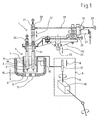
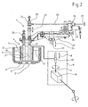
- the device for controlling the glass drop mass according to FIG. 1 is denoted by 1.
- the device 1 has two plungers 2 and 2 '.
- the plungers 2, 2 ' are arranged in a feeder head 3 of a feeder 4.
- the feeder head 3 has a double drop outlet, which is formed by two openings 5 and 5 'in a drip ring 6.
- the feeder head 3 has a throttle tube 7, which surrounds the two plungers 2, 2 '.
- the throttle tube 7 is changeable in a manner known per se in its serving as a manipulated variable axial position according to double arrow 8.
- a drive 9 of the throttle tube 7 is schematized in Fig. 1 and only partially shown.
- a motor which drives a spindle 11 via an angle gear 10.
- the spindle 11 cooperates with a spindle nut 12 connected to the throttle tube 7.
- a Mechanism (not shown) may be provided in order to adjust the throttle tube 7 to the symmetrical arrangement about the double drop outlet 5, 5 'around horizontally. Due to the vertical adjustment according to double arrow 8, a gap 15 between a lower end of the throttle tube 7 and the drip ring 6 is set.
- the glass level outside of the throttle tube 7 is denoted by 17, while the glass level within the throttle tube is denoted by 18.
- the glass shelf 18 depends on the glass shelf 17 and on the size of the gap 15. The glass shelf 18 ultimately determines the glass volume exiting from the perforations 5, 5 'per unit of time or per feeder cycle.
- the plungers 2, 2 ' are fastened in each case with fastening means 20 and 21 to a plunger holder 22.
- the plunger holder 22 is attached to a support column 23 which is vertically movable up and down, as indicated by double arrow 24.
- the drive mechanism for the support column 23, which is not shown, may be, for example, the drive mechanism according to the DE 203 16 501 U1 act.
- the plunger holder 22 has means 25 for horizontal basic adjustment.
- the height adjustment device 26 has a motor-gear unit 27, which drives a shaft 28.
- a hand wheel 29 allows a manual rotation of the shaft 28.
- the shaft 28 acts via a worm gear 30 on a guide member 31 of the fastening means 21 to move the plunger 2 'according to double arrow 32.
- both plungers are shown 2,2 'in a lower end position. This is a lower end position, which belongs to a certain movement profile of a number of different movement profiles of the plunger 2, 2 '.
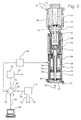
- Fig. 3 shows a preforming station 35 of a section 36 of an IS glass forming machine.
- the preforming station 35 has a preform bottom 37, preform halves 38 and 39, neck mold halves 40 and 41 and a press die 42.
- the press ram 42 is fastened in a manner known per se to the upper end of a piston rod 43 of a piston 44.
- the piston 44 is displaceable in a cylinder 45 of a piston-cylinder unit 46. Below the piston 44 there is a feed space 47 and above the piston 44, a retraction space 48.
- the piston 44 carries an actuating ring 49 for a ram position sensor 50, which in this case according to the EP 0 652 854 B1 is trained.
- the punch 42 is guided by a coaxial with the cylinder 45 guide cylinder 53.
- a spring 54 is also arranged, which moves the bladder 42 in its axial loading position shown in Fig. 3 at vented feed space 47 and vented retraction chamber 48.
- this loading position an upper tip of the press ram 42 just dips into an opening region of a preforming recess 56.
- the preform bottom 37 is removed, so that from above a glass drop can fall into the preforming recess 56 and onto the tip of the press ram 42.
- the piston rod 43 is hollow and receives a attached to a bottom 57 cooling air pipe 58.
- the cooling air pipe 58 is supplied with cooling air for the pressing punch 42 in the direction of an arrow 59.
- a connection for ventilation of the feed chamber 47 is designated 60, a connection for ventilation of the retraction chamber 48 with 61. Further means for ventilation of the feed space 47 and the retraction space 48 for performing a press cycle of the ram 42 are not shown. In particular, these may be agents according to the German patent application 103 16 600.9.
- the press ram position sensor 50 is connected via a signal amplifieri signal evaluation unit 65 to a signal input 66 of a software circuit 67 implemented in software.
- the control circuit 67 is further connected via a line 68 bidirectionally connected to an input / output unit 69.
- a signal output 70 of the control circuit 67 is connected by a line 72 to a common drive control 71 for the plunger holder 22 and the height adjustment device 26.
- a position signal is generated which provides information about the size of the maximum penetration depth of the press ram 42 into the mold. The greater the maximum penetration depth, the lower the drop mass that has entered the preforming recess 56.
- the measured ram end position is given by the signal amplifier / signal evaluation unit 65 to the control circuit 67.
- the control circuit 67 compares the measured ram end position with a set value for the ram end position, which has been input to the control circuit 67 via the input / output unit 69.
- the set values of the final punch position can be set separately for each preform station 35 of the I.S. glass forming machine.
- the deviation between the setpoint value and the actual value of the ram end position resulting therefrom is converted into a mass difference or a weight difference taking into account the known cross-sectional area of the ram 42.
- This mass difference is given to the drive controller 71 via the signal output 70.
- a real mean value of the mass differences of all drops of a machine cycle is formed.
- the determined mass differences of the single drops after scaling are used to alter one or more parameters of the motion profile of the plunger that created the drop.
- the scaling takes place in such a way that the scaled mass differences result in a "fictitious" mean value of zero given a sign-correct addition over one machine cycle.
- the throttle tube control loop and the plunger control circuit are connected in quasi-series.
- the drive controller 71 is connected via a signal line 74 to a motor, not shown, of the drive mechanism for the support column 23. Further, the drive controller 71 is connected via a signal line 75 to the stepper motor gear unit 27 of the height adjustment device 26 acting on the plunger 2 '.
- Another signal output 76 of the control circuit 67 is connected to a throttle tube drive control 77.
- a signal line 78 leads from the throttle tube drive control 77 to the drive 9 of the throttle tube 7.
- the device 1 according to FIG. 1 or 2 has a feeder head 3 with a double droplet outlet, it is provided that two drops each arrive simultaneously in each section of the IS glass forming machine, which are each processed in one of two preform stations 35 of the respective section.
- the 1.S. glass forming machine may be an 8-DG machine, which thus has eight sections and processes sixteen drops within one machine cycle.
- the two drops, which enter a section at the same time should have the same mass.
- a relatively simple assortment to be produced may comprise two different types of hollow glass containers, namely a lightweight hollow glass container and a heavy hollow glass container. In this case, it can be provided that the ignition sequence of a machine cycle is followed more easily by a heavy drop, a heavy one again, etc
- eight data sets for eight movement profiles of the plunger holder 22, ie for the eight feeder cycles of a machine cycle, are stored in the drive control 71.
- four motion profiles or data records will be identical after completion of an adjustment process, which usually only extends over a few machine cycles, so that the plunger holder 22 alternately performs only two movement sequences each time.
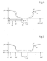
- these two plunger holder movement profiles are designated A and B.
- the abscissa shows the course of a feeder cycle, the beginning and the end of a feeder cycle being denoted by 0 ° and 360 °, respectively.
- the vertical position of the plunger holder 22 is plotted on the ordinate, wherein y1 denotes a lower end position of the plunger holder 22 and y2 denotes an upper end position of the plunger holder 22. Since the duration of a feeder cycle is predetermined, the motion profiles A and B represent the location and time of the plunger holder 22 via a feeder cycle.
- the movement profile A has a stoppage duration 85 which is longer than a corresponding stoppage duration 86 of the movement profile B. Since a longer stoppage duration of a plunger in its lower end position causes a smaller drop mass, the movement profile A is for the Sections of the 1.S.-glass forming machine provided, which are used for the production of the lighter hollow glass container, while the movement profile B is provided for the production of the drops for the heavier hollow glass containers. Furthermore, the movement profile A has a shorter standstill duration in the upper end position y2 in comparison to the movement profile B. According to movement profile B, the plunger holder 22 remains approximately between 355 ° and 5 ° in its upper end position y2.
- the time duration 87 of the downward movement according to movement profile B is almost equal to the time period 88 of the downward movement according to movement profile A.
- the standstill duration 85 in the lower end position y1 is longer than the almost zero-value standstill duration in the upper end position y2.
- the two motion profiles A and B are achieved by stepwise approximation, starting from in each case an initial movement for the movement profile A or movement profile B, by determining the mass difference for each drop generated within the machine cycle after passing through a machine cycle and a corresponding change of the associated motion profile the plunger holder 22 is made.
- This approximation method is completed when the mass actual values are sufficiently close to the respective mass setpoint value, ie the measured mass difference does not exceed a predetermined threshold value.
- the approximation method usually requires only a few machine cycles.
- FIG. 5 two further movement profiles C and D of the plunger holder 22 are shown, which should also be used for an assortment, as described in connection with FIG. 4.
- the motion profiles C and D differ from the motion profiles A and B primarily in that they describe different strokes of the plunger holder 22.
- the stroke of the movement profile C is the distance between a lower end position yc1 and an upper end position y2 of the plunger holder 22. While the upper end position of the plunger holder 22 according to the movement profile D is also y2, a lower end position yd1 is lower than in the movement profile C.
- Das Movement profile C causes the heavier drops to emerge from the feeder head 3, while the motion profile D causes the lighter drops to be dispensed. Because of the respective lower end position yc1 and yd1 the free cross section of the openings 5, 5 'is influenced.
- a stoppage period 95 of the plunger holder 22 in its lower end position yc1 or yd1 is the same for the two movement profiles C and D.
- the movement profile C differs from the movement profile D by the speed structure of the downward and upward movement. For example This difference in speed structure is shown between 60 ° and 150 ° and correspondingly in the symmetrical upward movements of the movement profiles C and D.
- the described parameters or other parameters of the plunger holder movement profiles can be changed to produce a desired drop size or drop contour.
- the speed at which the plunger carrier 22 is moved downwardly or upwardly near its lower end position can be varied. During the upward movement, with very viscous glass, a certain part of the glass is withdrawn again.
- an assortment with only two different article weights with alternating order in the firing order is to be produced, e.g. may also be provided that in the assortment, although only two different article weights are provided, but in a series of eight Feederzyklen an 8-DG machine initially two heavy droplet pairs (eg 168 g per drop), then five light droplet pairs (eg 160 g per Drop) and then again a heavy pair of drops to be generated.
- the sequence of the five light droplet pairs in sequence causes the glass shelf 18 within the choke tube 7 to increase progressively during the course of this sequence as less glass drains off. Without a corresponding regulation, the droplet pairs within this light sequence would have different masses. The same would apply to a heavy sequence.
- a regulation of the desired masses of the drops can be generated in a short time by setting an associated plunger movement profile for each drop produced.
- the movement profiles of the plungers 2, 2 ' are in a relatively coincident relationship with the movement profile of the plunger holder 22. This is the case when a controlled adjustment of the plunger 2 'relative to the plunger 2 is not provided. Such an adjustment of the plunger 2 ', however, may be required due to undesirable slight differences between the apertures 5, 5' in order to achieve that the two of the Openings 5, 5 'spent and reaching into the same section drops are equal. In general, this will be desired. If required, the plunger 2 'is adjusted from feeder cycle to feeder cycle by the height adjustment device 26, which is controlled via the drive control 71.
- Fig. 6 the strokes of the two plungers 2 and 2 'over three consecutive feeder cycles (abscissa) are shown.
- the ordinate h shows the relative height of the respective lower end of the plunger 2 or 2 'above the drip ring 6.
- the bars 98, 98 'and 98 show the strokes of the plunger 2 and their position during three consecutive feeder cycles, and the strokes of the plunger 2' and their position for the three feeder cycles are indicated by bars 99, 99 'and 99". shown.
- the plunger strokes 98 and 99 are the same, i. the maximum deflections of the plungers 2 and 2 'are the same because the plungers 2, 2' are fixed to the same plunger holder 22.
- the position of the plunger strokes 98 and 99 is different to compensate for minor size differences of the apertures 5, 5 'so that in the feeder cycle a pair of equal sized drops is produced.
- the plunger 2 ' unlike shown in FIGS. 1 and 2, slightly lower than the plunger 2 is attached to the plunger holder 22.
- the plunger strokes 98 and 99 are thus determined solely by the stroke movement of the plunger holder 22.
- plungers 2 and 2 ' have strokes 98' and 99 '. These are unchanged from the first feeder cycle shown, as well as their position, since in the example shown in Fig. 6, the approximation method has already been completed, that is set a desired balance with respect to the drop masses, and provided is to produce equal droplet masses during the first and second feeder cycle shown.
- the third feeder cycle shown By contrast, it is provided for the third feeder cycle shown to produce a larger drop mass.
- smaller plunger strokes 98 "and 99" are generated by the plunger holder 22 according to an associated record performs a correspondingly reduced stroke.
- This displacement of the plunger 2 ' is effected by a corresponding adjustment of the data set by means of the height adjustment device 26, preferably when the plunger 2' is in the region of its upper end position.
- the dynamics of the change in the stroke position of the plunger 2 ' is not shown in FIG. 6 for the sake of clarity.
Landscapes
- Chemical & Material Sciences (AREA)
- Engineering & Computer Science (AREA)
- Materials Engineering (AREA)
- Organic Chemistry (AREA)
- Re-Forming, After-Treatment, Cutting And Transporting Of Glass Products (AREA)
- Manufacture, Treatment Of Glass Fibers (AREA)
Claims (17)
- Procédé pour la régulation de la masse de paraisons lors de la fabrication de récipients en verre creux au moyen d'une machine à mouler le verre (36), dans lequel au moins un piston (2, 2') est disposé dans un distributeur (3) d'un dispositif d'alimentation (4) et il est prévu, pour le mouvement vertical vers le haut et le bas du piston (2, 2') au nombre d'un au moins, un profil de mouvement (A,B,C,D) qui peut être modifié pour influer sur l'écoulement de verre en fusion liquide hors du distributeur (3),
caractérisé en ce que la machine à mouler le verre est une machine à mouler le verre I.S. (à sections individuelles) (36) et, pour la fabrication simultanée d'un assortiment de récipients en verre creux de poids différents, il est prévu pour chaque section (36) de la machine à mouler le verre à sections individuelles un profil de mouvement (A,B,C,D) modifiable par piston (2,2'),
une différence de valeur de référence de masse est déterminée à partir d'une valeur de consigne de référence de masse et d'une valeur réelle de référence de masse mesurée sur la base d'au moins une des paraisons successives pour chaque poste de préformage (35) de chaque section (36),
le profil de mouvement (A,B,C,D) du piston est modifié pour chaque poste de préformage (35) en fonction de la différence de valeur de référence de masse déterminée pour celui-ci, de telle sorte qu'en répétant ensuite la détermination de la différence de valeur de référence de masse et en modifiant ensuite le profil de mouvement (A,B,C,D), la valeur réelle de référence de masse est progressivement rapprochée de la valeur de consigne de référence de masse. - Procédé selon la revendication 1, caractérisé en ce qu'après chaque cycle de machine complet le système vérifie pour chaque poste de préformage (35) si la différence de valeur de référence de masse dépasse un seuil et, si c'est le cas, le profil de mouvement (A,B,C,D) du piston est adapté pour le poste de préformage (35)
- Procédé selon la revendication 1 ou 2, caractérisé en ce que la durée d'arrêt (85,86) du piston (2,2') dans sa position de fin de course inférieure (y1 ; yc1, yd1) et/ou supérieure (y2) est modifiée.
- Procédé selon l'une ou l'ensemble des revendications précédentes, caractérisé en ce que la durée (87, 88) du mouvement vers le bas et/ou vers le haut du piston (2,2') est modifiée.
- Procédé selon l'une ou l'ensemble des revendications précédentes, caractérisé en ce que la courbe de vitesse pour le mouvement vers le bas et/ou vers le haut du piston (2,2') est modifiée.
- Procédé selon l'une ou l'ensemble des revendications précédentes, caractérisé en ce que la course du piston (98, 98', 98", 99, 99', 99") est modifiée.
- Procédé selon l'une ou l'ensemble des revendications précédentes caractérisé en ce que la position (98, 98', 98", 99, 99', 99") de la course du piston par rapport à une bague pare-gouttes (6) du distributeur (3) est modifiée.
- Procédé selon l'une ou l'ensemble des revendications précédentes, caractérisé en ce qu'il est prévu au moins un porte-pistons (22) sensiblement horizontal et chaque profil de mouvement de piston est déterminé par un ensemble de données pour un profil de mouvement (A,B,C,D) correspondant du porte-pistons (22).
- Procédé selon la revendication 8, caractérisé en ce que, lorsqu'il existe plusieurs pistons (2,2') par section (36), il est prévu en complément de l'ensemble de données correspondant pour le porte-pistons (22) ou des ensembles de données pour les porte-pistons (22), un ensemble de données pour un profil (99, 99', 99") pour chacun des pistons (2'), à l'exception d'un premier piston (2), pour le déplacement du piston (2') par rapport à son porte-piston (22).
- Procédé selon l'une ou l'ensemble des revendications précédentes, caractérisé en ce que lorsque, en complément de la position axiale d'un tube d'étranglement (7) du distributeur (3), la compensation des effets de la modification de la viscosité du verre fondu liquide ou des modifications du niveau du verre (17, 18) dans le distributeur (3) est régulée en fonction de la masse des récipients en verre à fabriquer, une moyenne réelle est calculée à partir des différences de valeur de référence de masse de toutes les paraisons d'un cycle de la machine et celle-ci est rapprochée de zéro par la modification de la position axiale du tube d'étranglement (7) entre deux cycles de la machine, et les différences de valeur de référence de masse sont en outre cadrées de façon à obtenir à partir des différence de valeur de référence de masse cadrées une moyenne fictive de zéro, et la modification des profils de mouvement (A,B,C,D) des pistons est effectuée sur la base des différences de référence de masse cadrées.
- Dispositif (1) pour la régulation de la masse de paraisons lors de la fabrication de récipients en verre creux au moyen d'une machine à mouler le verre (36), possédant au moins un piston (2, 2') disposé dans un distributeur (3) d'un dispositif d'alimentation (4) et des moyens (22, 23, 26) pour le mouvement vertical vers le haut et le bas du piston (2, 2') au nombre d'un au moins, un profil de mouvement (A,B,C,D) pour le mouvement du piston qui peut être modifié pour influer sur l'écoulement de verre en fusion liquide hors du distributeur (3) étant enregistré dans une unité de commande (71) du dispositif (1),
caractérisé en ce que la machine à mouler le verre est une machine à mouler le verre I.S. (à sections individuelles) (36) et, pour la fabrication simultanée d'un assortiment de récipients en verre creux de poids différents, un profil de mouvement (A,B,C,D) modifiable par piston (2,2'), peut être enregistré dans l'unité de commande (71) pour chaque section (36) de la machine à mouler le verre à sections individuelles.
Le dispositif (1) présente des moyens (67) pour déterminer une différence de valeur de référence de masse à partir d'une valeur de consigne de référence de masse et d'une valeur réelle de référence de masse mesurée sur la base d'au moins une des paraisons successives pour chaque poste de préformage (35) de chaque section (36),
et l'unité de commande (71) est reliée par une ligne de données (72) avec les moyens (67) pour déterminer la différence de valeur de référence de masse et elle est conçue pour modifier le profil de mouvement (A,B,C,D) du piston pour chaque poste de préformage (35) en fonction de la différence de valeur de référence de masse déterminée pour celui-ci, de telle sorte qu'en répétant ensuite la détermination de la différence de valeur de référence de masse et en modifiant ensuite le profil de mouvement (A,B,C,D), la valeur réelle de référence de masse est progressivement rapprochée de la valeur de consigne de référence de masse. - Dispositif selon la revendication 11, caractérisé en ce que le dispositif (1) est conçu pour vérifier, après chaque cycle de machine complet et pour chaque poste de préformage (35), si la différence de valeur de référence de masse dépasse un seuil et, si c'est le cas, pour adapter le profil de mouvement (A,B,C,D) du piston pour le poste de préformage (35).
- Dispositif selon la revendication 11 ou 12, caractérisé en ce que le dispositif (1) est conçu pour modifier les profils de mouvement du piston (A,B,C,D) en modifiant un paramètre ou une combinaison de plusieurs paramètres dans le groupe comprenant la durée d'arrêt (85, 86) de chaque piston (2,2') dans sa position de fin de course inférieure (y1 ; yc1, yd1) et/ou supérieure (y2), la durée (87, 88) du mouvement vers le bas et/ou vers le haut du piston (2,2'), la courbe de vitesse du mouvement vers le bas et/ou vers le haut du piston (2,2'), la course du piston (98, 98', 98", 99, 98', 99") et la position (98, 98', 98", 99, 99', 99") de la course du piston par rapport à une bague pare-gouttes (6) du distributeur (3).
- Dispositif selon l'une ou l'ensemble des revendications 11 à 13, caractérisé en ce que le dispositif (1) présente au moins un porte-pistons (22) sensiblement horizontal et chaque profil de mouvement de piston est déterminé par un ensemble de données mémorisé dans l'unité de commande (71) pour un profil de mouvement (A,B,C,D) correspondant du porte-pistons (22).
- Dispositif selon la revendication 14, caractérisé en ce que tous les pistons (2,2') d'un porte-pistons (22) sont fixés ensemble et l'unité de commande est une commande d'entraînement (71) du porte-pistons (22).
- Dispositif selon la revendication 14 ou 15, caractérisé en ce que le dispositif (1) comprend plusieurs pistons (2,2') et pour chaque section (36), en complément de l'ensemble de données du porte-pistons (22) ou des ensembles de données pour les porte-pistons (22), un ensemble de données peut être mémorisé dans une commande d'entraînement (71) correspondante pour chacun des pistons (2'), à l'exception d'un premier piston (2), pour un profil (99, 99', 99") pour le déplacement du piston (2') par rapport à son porte-pistons (22) au moyen d'un dispositif de réglage de la hauteur (26).
- Dispositif selon l'une ou l'ensemble des revendications 11 à 16, caractérisé en ce que le dispositif (1) est conçu pour, lorsqu'il est prévu en outre un circuit de régulation pour la position axiale d'un tube d'étranglement (7) du distributeur (3) en vue de la compensation des effets des variations viscosité du verre fondu liquide ou des modifications du niveau du verre dans le distributeur (3) en fonction de la masse des récipients en verre à fabriquer, calculer une moyenne réelle à partir des différences de valeur de référence de masse de toutes les paraisons d'un cycle de la machine et rapprocher celle-ci de zéro en modifiant la position axiale du tube d'étranglement (7) entre deux cycles de la machine, et pour cadrer en outre les différences de valeur de référence de masse de façon à obtenir, à partir des différence de valeur de référence de masse cadrées, une moyenne fictive de zéro, et pour modifier les profils de mouvement (A,B,C,D) des pistons sur la base des différences de référence de masse cadrées.
Applications Claiming Priority (3)
| Application Number | Priority Date | Filing Date | Title |
|---|---|---|---|
| DE102004011647 | 2004-03-10 | ||
| DE102004011647A DE102004011647A1 (de) | 2004-03-10 | 2004-03-10 | Verfahren und Vorrichtung zur Regelung der Glastropfenmasse bei der Herstellung von Hohlglasbehältern |
| PCT/EP2005/002302 WO2005087670A1 (fr) | 2004-03-10 | 2005-03-04 | Procede et dispositif pour reguler la masse de gouttage de verre lors de la realisation de recipients en verre creux |
Publications (2)
| Publication Number | Publication Date |
|---|---|
| EP1599424A1 EP1599424A1 (fr) | 2005-11-30 |
| EP1599424B1 true EP1599424B1 (fr) | 2007-11-07 |
Family
ID=34895139
Family Applications (1)
| Application Number | Title | Priority Date | Filing Date |
|---|---|---|---|
| EP05715733A Expired - Lifetime EP1599424B1 (fr) | 2004-03-10 | 2005-03-04 | Procede et dispositif pour reguler la masse de gouttage de verre lors de la realisation de recipients en verre creux |
Country Status (7)
| Country | Link |
|---|---|
| US (1) | US20060213226A1 (fr) |
| EP (1) | EP1599424B1 (fr) |
| AT (1) | ATE377576T1 (fr) |
| BR (1) | BRPI0508636B1 (fr) |
| DE (2) | DE102004011647A1 (fr) |
| MX (1) | MXPA06009303A (fr) |
| WO (1) | WO2005087670A1 (fr) |
Families Citing this family (6)
| Publication number | Priority date | Publication date | Assignee | Title |
|---|---|---|---|---|
| EP2610223B1 (fr) * | 2011-12-27 | 2017-09-27 | BDF Industries S.p.A. | Procédé et dispositif de contrôle de la quantité de paraisons de verre |
| CN106237893B (zh) * | 2016-09-28 | 2019-02-15 | 山东三金玻璃机械有限公司 | 一种供料机匀料装置 |
| US10865132B2 (en) * | 2018-08-14 | 2020-12-15 | Emhart Glass | Apparatus and method to control gob weight, length and/or shape |
| IT201800009629A1 (it) * | 2018-10-19 | 2020-04-19 | Bottero Spa | Gruppo punzone per la formatura di cordoni di vetro fuso |
| FR3094978B1 (fr) * | 2019-04-11 | 2021-04-23 | Soc Europeenne Des Produits Refractaires | Ensemble cuvette d’avant-corps d’un canal de distribution de verre |
| EP3915949B1 (fr) * | 2020-05-29 | 2024-07-03 | Emhart Glass S.A. | Machine de formation de verre ayant des positions d'extrémité de piston à commande individuelle |
Family Cites Families (18)
| Publication number | Priority date | Publication date | Assignee | Title |
|---|---|---|---|---|
| US1732711A (en) * | 1920-05-04 | 1929-10-22 | Westinghouse Electric & Mfg Co | Control system |
| US1955869A (en) * | 1931-12-11 | 1934-04-24 | Wood John Thomas | Apparatus for feeding predetermined different weights of molten glass |
| US4551163A (en) * | 1984-06-04 | 1985-11-05 | Emhart Industries, Inc. | Electronic glass feeder plunger operating mechanism |
| US4682998A (en) * | 1985-09-09 | 1987-07-28 | Vitro Tec Fideicomiso | Electronic system for automatically controlling the weight of glass gobs in a molten glass feeder |
| JPH02267125A (ja) * | 1989-04-07 | 1990-10-31 | Hoya Corp | ガラス製品成形装置 |
| ATE184582T1 (de) * | 1993-02-25 | 1999-10-15 | Owens Brockway Glass Container | Glasspeisevorrichtung mit mehreren öffnungen |
| US5885317A (en) * | 1993-02-25 | 1999-03-23 | Owens-Brockway Glass Container Inc. | Multiple orifice glass feed system |
| DE9404164U1 (de) * | 1993-05-27 | 1994-05-19 | Fa. Hermann Heye, 31683 Obernkirchen | Wegaufnehmer für den Positionsnachweis eines Preßstempels |
| IT1267393B1 (it) * | 1994-02-18 | 1997-02-05 | Bottero Spa | Impianto per la formatura di articoli in vetro. |
| US5660610A (en) * | 1994-10-24 | 1997-08-26 | Owens-Brockway Glass Container Inc. | Remotely adjustable glass feeder needle assembly |
| JPH08333121A (ja) * | 1995-05-31 | 1996-12-17 | Toshiba Glass Co Ltd | ゴブ重量制御方法およびその装置 |
| US5779749A (en) * | 1997-04-21 | 1998-07-14 | Owens-Brockway Glass Container Inc. | Generation of needle motion profile in an individual section glassware forming system |
| JPH1160247A (ja) * | 1997-08-08 | 1999-03-02 | Toyo Glass Kikai Kk | ゴブ重量制御装置 |
| ATE309967T1 (de) * | 2001-06-12 | 2005-12-15 | Glas Heinz Gmbh | Verfahren und vorrichtung für die gleichzeitige herstellung von glasprodukten mit unterschiedlicher masse |
| DE10133019C1 (de) * | 2001-07-06 | 2003-01-30 | Hermann Heye I Ins Fa | Verfahren und Vorrichtung zur Bestimmung der Masse eines frei fallenden, schmelzflüssigen Glastropfens |
| DE10254654A1 (de) * | 2002-11-22 | 2004-06-09 | Heinz-Glas Gmbh | Vorrichtung und Verfahren zur Verarbeitung von Glasposten unterschiedlicher Massen und Speisevorrichtung |
| DE10316600A1 (de) * | 2003-04-11 | 2004-11-04 | Heye International Gmbh | Verfahren und Vorrichtung zum Antrieb eines Pressstempels einer Glasformmaschine |
| DE20316501U1 (de) * | 2003-10-25 | 2003-12-24 | Heye International Gmbh | Vorrichtung zum Auf- und Abbewegen von Plungern in einem Speiserkopf für eine Glasformmaschine |
-
2004
- 2004-03-10 DE DE102004011647A patent/DE102004011647A1/de not_active Ceased
-
2005
- 2005-03-04 US US10/564,899 patent/US20060213226A1/en not_active Abandoned
- 2005-03-04 BR BRPI0508636-1A patent/BRPI0508636B1/pt not_active IP Right Cessation
- 2005-03-04 AT AT05715733T patent/ATE377576T1/de not_active IP Right Cessation
- 2005-03-04 EP EP05715733A patent/EP1599424B1/fr not_active Expired - Lifetime
- 2005-03-04 WO PCT/EP2005/002302 patent/WO2005087670A1/fr not_active Ceased
- 2005-03-04 DE DE502005001858T patent/DE502005001858D1/de not_active Expired - Lifetime
- 2005-03-04 MX MXPA06009303A patent/MXPA06009303A/es active IP Right Grant
Also Published As
| Publication number | Publication date |
|---|---|
| ATE377576T1 (de) | 2007-11-15 |
| EP1599424A1 (fr) | 2005-11-30 |
| MXPA06009303A (es) | 2007-01-26 |
| BRPI0508636B1 (pt) | 2015-06-02 |
| BRPI0508636A (pt) | 2007-08-07 |
| US20060213226A1 (en) | 2006-09-28 |
| WO2005087670A1 (fr) | 2005-09-22 |
| DE502005001858D1 (de) | 2007-12-20 |
| DE102004011647A1 (de) | 2005-09-29 |
Similar Documents
| Publication | Publication Date | Title |
|---|---|---|
| DE3208502C2 (de) | Glasformmaschine | |
| DE3816273C2 (fr) | ||
| EP0776752B1 (fr) | Procédé de moulage par soufflage de corps creux en matière thermoplastique | |
| EP0275875A2 (fr) | Dispositif de réglage pour une cage de laminoir universelle | |
| DE3718961C2 (fr) | ||
| DE69517215T2 (de) | Vorrichtung zur Herstellung von Glasgegenständen | |
| EP1599424B1 (fr) | Procede et dispositif pour reguler la masse de gouttage de verre lors de la realisation de recipients en verre creux | |
| EP0732194B1 (fr) | Procédé et dispositif de mesure et de réglage de la position du coulisseau d'une presse à découper à grande vitesse | |
| EP0451239B1 (fr) | Procede de fabrication de pieces creuses en matiere thermoplastique | |
| DE102010060308B4 (de) | Vorrichtung und Verfahren zur Mehrfachabfüllung hochviskoser Materialien | |
| DE2743058B1 (de) | Verfahren zum Steuern der Bewegung eines ueber eine Kurvenscheibe angetriebenen Formtisches eines Thermoformautomaten und Thermoformautomat | |
| EP1897858B1 (fr) | Dispositif destiné au formage d'articles en verre | |
| EP1598321B1 (fr) | Procédure et dispositif pour la production des masses divergentes des paraisons en verre avec la production des articles de verre | |
| EP1791440B9 (fr) | Procede et installation pour la fabrication de produits de confiserie | |
| EP1466871B1 (fr) | Procédé et dispositif de commande du poinçon ébaucheur d'ume machine à façonner le verre | |
| DE3232733C1 (de) | Verfahren zur Steuerung einer Maschine zur Verarbeitung von Glas oder anderen thermoplastischen Massen | |
| DE68902061T2 (de) | Glasformmaschine. | |
| EP0685315B1 (fr) | Procédé pour la production de corps creux en matière thermoplastique par extrusion soufflage | |
| DE69802714T2 (de) | Vorrichtung zur behandlung von geschmolzenem glas | |
| EP0263409B1 (fr) | Procédé et appareil pour déformer une paraison en verre | |
| DE3446620C2 (fr) | ||
| EP3892399B1 (fr) | Système de piston de coulée et procédé de coulée pour une machine à couler sous pression | |
| EP0013574B1 (fr) | Dispositif de cueillage de verre fondu | |
| DE3330076C2 (fr) | ||
| DE19652308B4 (de) | Dynamische Iterative Stempel-Regelung des Preßvorganges beim Vielstempelpressen |
Legal Events
| Date | Code | Title | Description |
|---|---|---|---|
| PUAI | Public reference made under article 153(3) epc to a published international application that has entered the european phase |
Free format text: ORIGINAL CODE: 0009012 |
|
| 17P | Request for examination filed |
Effective date: 20050721 |
|
| AK | Designated contracting states |
Kind code of ref document: A1 Designated state(s): AT BE BG CH CY CZ DE DK EE ES FI FR GB GR HU IE IS IT LI LT LU MC NL PL PT RO SE SI SK TR |
|
| AX | Request for extension of the european patent |
Extension state: AL BA HR LV MK YU |
|
| GRAP | Despatch of communication of intention to grant a patent |
Free format text: ORIGINAL CODE: EPIDOSNIGR1 |
|
| RBV | Designated contracting states (corrected) |
Designated state(s): AT BE BG CH CY CZ DE DK EE ES FI FR GB GR HU IE IS IT LI LT LU MC NL PL PT RO SE SI SK TR |
|
| GRAS | Grant fee paid |
Free format text: ORIGINAL CODE: EPIDOSNIGR3 |
|
| DAX | Request for extension of the european patent (deleted) | ||
| GRAA | (expected) grant |
Free format text: ORIGINAL CODE: 0009210 |
|
| AK | Designated contracting states |
Kind code of ref document: B1 Designated state(s): AT BE BG CH CY CZ DE DK EE ES FI FR GB GR HU IE IS IT LI LT LU MC NL PL PT RO SE SI SK TR |
|
| REG | Reference to a national code |
Ref country code: GB Ref legal event code: FG4D Free format text: NOT ENGLISH |
|
| REG | Reference to a national code |
Ref country code: IE Ref legal event code: FG4D Free format text: LANGUAGE OF EP DOCUMENT: GERMAN |
|
| REG | Reference to a national code |
Ref country code: CH Ref legal event code: EP Ref country code: CH Ref legal event code: NV Representative=s name: A. BRAUN, BRAUN, HERITIER, ESCHMANN AG PATENTANWAE |
|
| REF | Corresponds to: |
Ref document number: 502005001858 Country of ref document: DE Date of ref document: 20071220 Kind code of ref document: P |
|
| GBT | Gb: translation of ep patent filed (gb section 77(6)(a)/1977) |
Effective date: 20071212 |
|
| REG | Reference to a national code |
Ref country code: SE Ref legal event code: TRGR |
|
| PG25 | Lapsed in a contracting state [announced via postgrant information from national office to epo] |
Ref country code: ES Free format text: LAPSE BECAUSE OF FAILURE TO SUBMIT A TRANSLATION OF THE DESCRIPTION OR TO PAY THE FEE WITHIN THE PRESCRIBED TIME-LIMIT Effective date: 20080218 Ref country code: NL Free format text: LAPSE BECAUSE OF FAILURE TO SUBMIT A TRANSLATION OF THE DESCRIPTION OR TO PAY THE FEE WITHIN THE PRESCRIBED TIME-LIMIT Effective date: 20071107 |
|
| NLV1 | Nl: lapsed or annulled due to failure to fulfill the requirements of art. 29p and 29m of the patents act | ||
| PG25 | Lapsed in a contracting state [announced via postgrant information from national office to epo] |
Ref country code: LT Free format text: LAPSE BECAUSE OF FAILURE TO SUBMIT A TRANSLATION OF THE DESCRIPTION OR TO PAY THE FEE WITHIN THE PRESCRIBED TIME-LIMIT Effective date: 20071107 Ref country code: PL Free format text: LAPSE BECAUSE OF FAILURE TO SUBMIT A TRANSLATION OF THE DESCRIPTION OR TO PAY THE FEE WITHIN THE PRESCRIBED TIME-LIMIT Effective date: 20071107 Ref country code: SI Free format text: LAPSE BECAUSE OF FAILURE TO SUBMIT A TRANSLATION OF THE DESCRIPTION OR TO PAY THE FEE WITHIN THE PRESCRIBED TIME-LIMIT Effective date: 20071107 Ref country code: IS Free format text: LAPSE BECAUSE OF FAILURE TO SUBMIT A TRANSLATION OF THE DESCRIPTION OR TO PAY THE FEE WITHIN THE PRESCRIBED TIME-LIMIT Effective date: 20080307 Ref country code: BG Free format text: LAPSE BECAUSE OF FAILURE TO SUBMIT A TRANSLATION OF THE DESCRIPTION OR TO PAY THE FEE WITHIN THE PRESCRIBED TIME-LIMIT Effective date: 20080207 |
|
| REG | Reference to a national code |
Ref country code: CH Ref legal event code: PFA Owner name: HEYE INTERNATIONAL GMBH Free format text: HEYE INTERNATIONAL GMBH#LOHPLATZ 1#31683 OBERNKIRCHEN (DE) -TRANSFER TO- HEYE INTERNATIONAL GMBH#LOHPLATZ 1#31683 OBERNKIRCHEN (DE) |
|
| ET | Fr: translation filed | ||
| PG25 | Lapsed in a contracting state [announced via postgrant information from national office to epo] |
Ref country code: DK Free format text: LAPSE BECAUSE OF FAILURE TO SUBMIT A TRANSLATION OF THE DESCRIPTION OR TO PAY THE FEE WITHIN THE PRESCRIBED TIME-LIMIT Effective date: 20071107 |
|
| PG25 | Lapsed in a contracting state [announced via postgrant information from national office to epo] |
Ref country code: SK Free format text: LAPSE BECAUSE OF FAILURE TO SUBMIT A TRANSLATION OF THE DESCRIPTION OR TO PAY THE FEE WITHIN THE PRESCRIBED TIME-LIMIT Effective date: 20071107 Ref country code: RO Free format text: LAPSE BECAUSE OF FAILURE TO SUBMIT A TRANSLATION OF THE DESCRIPTION OR TO PAY THE FEE WITHIN THE PRESCRIBED TIME-LIMIT Effective date: 20071107 |
|
| PLBE | No opposition filed within time limit |
Free format text: ORIGINAL CODE: 0009261 |
|
| STAA | Information on the status of an ep patent application or granted ep patent |
Free format text: STATUS: NO OPPOSITION FILED WITHIN TIME LIMIT |
|
| BERE | Be: lapsed |
Owner name: HEYE INTERNATIONAL G.M.B.H. Effective date: 20080331 |
|
| PG25 | Lapsed in a contracting state [announced via postgrant information from national office to epo] |
Ref country code: PT Free format text: LAPSE BECAUSE OF FAILURE TO SUBMIT A TRANSLATION OF THE DESCRIPTION OR TO PAY THE FEE WITHIN THE PRESCRIBED TIME-LIMIT Effective date: 20080407 |
|
| REG | Reference to a national code |
Ref country code: IE Ref legal event code: FD4D |
|
| 26N | No opposition filed |
Effective date: 20080808 |
|
| PG25 | Lapsed in a contracting state [announced via postgrant information from national office to epo] |
Ref country code: IE Free format text: LAPSE BECAUSE OF FAILURE TO SUBMIT A TRANSLATION OF THE DESCRIPTION OR TO PAY THE FEE WITHIN THE PRESCRIBED TIME-LIMIT Effective date: 20071107 Ref country code: MC Free format text: LAPSE BECAUSE OF NON-PAYMENT OF DUE FEES Effective date: 20080331 |
|
| PG25 | Lapsed in a contracting state [announced via postgrant information from national office to epo] |
Ref country code: GR Free format text: LAPSE BECAUSE OF FAILURE TO SUBMIT A TRANSLATION OF THE DESCRIPTION OR TO PAY THE FEE WITHIN THE PRESCRIBED TIME-LIMIT Effective date: 20080208 Ref country code: EE Free format text: LAPSE BECAUSE OF FAILURE TO SUBMIT A TRANSLATION OF THE DESCRIPTION OR TO PAY THE FEE WITHIN THE PRESCRIBED TIME-LIMIT Effective date: 20071107 |
|
| PG25 | Lapsed in a contracting state [announced via postgrant information from national office to epo] |
Ref country code: FI Free format text: LAPSE BECAUSE OF FAILURE TO SUBMIT A TRANSLATION OF THE DESCRIPTION OR TO PAY THE FEE WITHIN THE PRESCRIBED TIME-LIMIT Effective date: 20071107 Ref country code: BE Free format text: LAPSE BECAUSE OF NON-PAYMENT OF DUE FEES Effective date: 20080331 |
|
| PG25 | Lapsed in a contracting state [announced via postgrant information from national office to epo] |
Ref country code: CY Free format text: LAPSE BECAUSE OF FAILURE TO SUBMIT A TRANSLATION OF THE DESCRIPTION OR TO PAY THE FEE WITHIN THE PRESCRIBED TIME-LIMIT Effective date: 20071107 |
|
| PG25 | Lapsed in a contracting state [announced via postgrant information from national office to epo] |
Ref country code: AT Free format text: LAPSE BECAUSE OF NON-PAYMENT OF DUE FEES Effective date: 20080304 |
|
| PG25 | Lapsed in a contracting state [announced via postgrant information from national office to epo] |
Ref country code: HU Free format text: LAPSE BECAUSE OF FAILURE TO SUBMIT A TRANSLATION OF THE DESCRIPTION OR TO PAY THE FEE WITHIN THE PRESCRIBED TIME-LIMIT Effective date: 20080508 Ref country code: LU Free format text: LAPSE BECAUSE OF NON-PAYMENT OF DUE FEES Effective date: 20080304 |
|
| REG | Reference to a national code |
Ref country code: DE Ref legal event code: R082 Ref document number: 502005001858 Country of ref document: DE Representative=s name: SOBISCH & KRAMM, DE |
|
| REG | Reference to a national code |
Ref country code: CH Ref legal event code: PCAR Free format text: NEW ADDRESS: HOLBEINSTRASSE 36-38, 4051 BASEL (CH) |
|
| REG | Reference to a national code |
Ref country code: FR Ref legal event code: PLFP Year of fee payment: 12 |
|
| REG | Reference to a national code |
Ref country code: FR Ref legal event code: PLFP Year of fee payment: 13 |
|
| REG | Reference to a national code |
Ref country code: FR Ref legal event code: PLFP Year of fee payment: 14 |
|
| REG | Reference to a national code |
Ref country code: DE Ref legal event code: R082 Ref document number: 502005001858 Country of ref document: DE Representative=s name: MICHALSKI HUETTERMANN & PARTNER PATENTANWAELTE, DE |
|
| PGFP | Annual fee paid to national office [announced via postgrant information from national office to epo] |
Ref country code: FR Payment date: 20210323 Year of fee payment: 17 Ref country code: CZ Payment date: 20210304 Year of fee payment: 17 Ref country code: CH Payment date: 20210319 Year of fee payment: 17 Ref country code: IT Payment date: 20210329 Year of fee payment: 17 |
|
| PGFP | Annual fee paid to national office [announced via postgrant information from national office to epo] |
Ref country code: TR Payment date: 20210225 Year of fee payment: 17 Ref country code: SE Payment date: 20210319 Year of fee payment: 17 Ref country code: GB Payment date: 20210324 Year of fee payment: 17 |
|
| PGFP | Annual fee paid to national office [announced via postgrant information from national office to epo] |
Ref country code: DE Payment date: 20220329 Year of fee payment: 18 |
|
| PG25 | Lapsed in a contracting state [announced via postgrant information from national office to epo] |
Ref country code: CZ Free format text: LAPSE BECAUSE OF NON-PAYMENT OF DUE FEES Effective date: 20220304 |
|
| REG | Reference to a national code |
Ref country code: CH Ref legal event code: PL |
|
| GBPC | Gb: european patent ceased through non-payment of renewal fee |
Effective date: 20220304 |
|
| PG25 | Lapsed in a contracting state [announced via postgrant information from national office to epo] |
Ref country code: SE Free format text: LAPSE BECAUSE OF NON-PAYMENT OF DUE FEES Effective date: 20220305 Ref country code: LI Free format text: LAPSE BECAUSE OF NON-PAYMENT OF DUE FEES Effective date: 20220331 Ref country code: GB Free format text: LAPSE BECAUSE OF NON-PAYMENT OF DUE FEES Effective date: 20220304 Ref country code: FR Free format text: LAPSE BECAUSE OF NON-PAYMENT OF DUE FEES Effective date: 20220331 Ref country code: CH Free format text: LAPSE BECAUSE OF NON-PAYMENT OF DUE FEES Effective date: 20220331 |
|
| PG25 | Lapsed in a contracting state [announced via postgrant information from national office to epo] |
Ref country code: IT Free format text: LAPSE BECAUSE OF NON-PAYMENT OF DUE FEES Effective date: 20220304 |
|
| REG | Reference to a national code |
Ref country code: DE Ref legal event code: R119 Ref document number: 502005001858 Country of ref document: DE |
|
| PG25 | Lapsed in a contracting state [announced via postgrant information from national office to epo] |
Ref country code: DE Free format text: LAPSE BECAUSE OF NON-PAYMENT OF DUE FEES Effective date: 20231003 |