EP1599424B1 - Method and device for regulating the glass gob during the production of hollow glass containers - Google Patents
Method and device for regulating the glass gob during the production of hollow glass containers Download PDFInfo
- Publication number
- EP1599424B1 EP1599424B1 EP05715733A EP05715733A EP1599424B1 EP 1599424 B1 EP1599424 B1 EP 1599424B1 EP 05715733 A EP05715733 A EP 05715733A EP 05715733 A EP05715733 A EP 05715733A EP 1599424 B1 EP1599424 B1 EP 1599424B1
- Authority
- EP
- European Patent Office
- Prior art keywords
- plunger
- mass reference
- mass
- glass
- movement
- Prior art date
- Legal status (The legal status is an assumption and is not a legal conclusion. Google has not performed a legal analysis and makes no representation as to the accuracy of the status listed.)
- Active
Links
- 239000011521 glass Substances 0.000 title claims abstract description 63
- 238000000034 method Methods 0.000 title claims abstract description 34
- 238000004519 manufacturing process Methods 0.000 title claims abstract description 20
- 230000001105 regulatory effect Effects 0.000 title claims description 3
- 230000033001 locomotion Effects 0.000 claims abstract description 131
- 238000007496 glass forming Methods 0.000 claims abstract description 22
- 239000006060 molten glass Substances 0.000 claims abstract description 9
- 230000008859 change Effects 0.000 claims description 26
- 230000001276 controlling effect Effects 0.000 claims description 6
- 230000000694 effects Effects 0.000 claims description 6
- 230000008569 process Effects 0.000 description 6
- 230000007246 mechanism Effects 0.000 description 5
- 238000006073 displacement reaction Methods 0.000 description 4
- 238000001816 cooling Methods 0.000 description 3
- 238000010304 firing Methods 0.000 description 3
- 230000035515 penetration Effects 0.000 description 3
- 238000009423 ventilation Methods 0.000 description 3
- 238000011156 evaluation Methods 0.000 description 2
- 239000000156 glass melt Substances 0.000 description 2
- 238000003825 pressing Methods 0.000 description 2
- 230000009467 reduction Effects 0.000 description 2
- 125000006850 spacer group Chemical group 0.000 description 2
- 201000005569 Gout Diseases 0.000 description 1
- 230000006978 adaptation Effects 0.000 description 1
- 238000013459 approach Methods 0.000 description 1
- 239000003990 capacitor Substances 0.000 description 1
- 239000005356 container glass Substances 0.000 description 1
- 238000005520 cutting process Methods 0.000 description 1
- 238000010586 diagram Methods 0.000 description 1
- 238000003780 insertion Methods 0.000 description 1
- 230000037431 insertion Effects 0.000 description 1
- 238000012545 processing Methods 0.000 description 1
- 238000005303 weighing Methods 0.000 description 1
Images

Classifications
-
- C—CHEMISTRY; METALLURGY
- C03—GLASS; MINERAL OR SLAG WOOL
- C03B—MANUFACTURE, SHAPING, OR SUPPLEMENTARY PROCESSES
- C03B7/00—Distributors for the molten glass; Means for taking-off charges of molten glass; Producing the gob, e.g. controlling the gob shape, weight or delivery tact
- C03B7/08—Feeder spouts, e.g. gob feeders
- C03B7/086—Plunger mechanisms
-
- C—CHEMISTRY; METALLURGY
- C03—GLASS; MINERAL OR SLAG WOOL
- C03B—MANUFACTURE, SHAPING, OR SUPPLEMENTARY PROCESSES
- C03B7/00—Distributors for the molten glass; Means for taking-off charges of molten glass; Producing the gob, e.g. controlling the gob shape, weight or delivery tact
- C03B7/005—Controlling, regulating or measuring
Definitions
- the invention relates to a method and a device according to the preamble of claim 1 or claim 11.
- a generic method and a generic device are each from the EP 0 612 698 B1 and the US Pat. No. 6,272,885 B1 known.
- a plurality of plungers which are each assigned to one of a plurality of drop outlets, are present.
- the aim is to achieve the greatest possible uniformity of the drops dispensed from the various droplet outlets.
- a control system is provided which serves to monitor the vertical position of each plunger and with which these vertical positions can be controlled individually depending on a measured drop weight.
- Each plunger is attached to an individual plunger holder, each connected to a drive.
- the DE 100 18 270 A1 describes an apparatus and a method for producing glass compacts wherein two control loops are used with respect to the stroke position and the temperature of the glass melt to keep the drop weight constant.
- the bottom dead center of the plunger can be changed by means of a movable stop, which is around the Piston rod of the plunger is arranged around and cooperates with a stop attached to the piston rod stop.
- a change of the bottom dead center can also be effected by inserting spacers between the slidable and the fixed stop.
- the sliding stop can also be adjusted by automatic means - as an alternative to a handwheel - but no regulation is revealed by a stepwise approach to the desired drop mass by corresponding comparison of an actual value with a target value. The same applies to the described automatic insertion of the spacers by means of a pneumatic piston-cylinder unit.
- variable drop weight feeder for container glass is known ("Electronic Feeder Type TSE" from J. Walter Co. Maschinen GmbH, 96352 Wilhelmsthal, Germany).
- electro Feeder Type TSE a variable drop weight feeder for container glass
- a programmable plunger motion profile can be manually modified by altering vertices from an operator via a graphical user interface. Likewise, the stroke position of a plunger can be changed.
- the EP 1 266 869 A1 mentions in general the possibility of creating goblets of different sizes by controlling the plunger in its timing as well as in its actuating travel.
- the EP 1 422 200 A2 which has been published after the priority date of the present application, relates to a device for the simultaneous production of glass products of different mass, wherein a change of various parameters of the motion profile of a plunger is provided. However, this device also has no regulation of the drop mass.
- the movement profile of the plunger or the associated plunger holder also has an influence on the mass or contour of a droplet dispensed through the droplet outlet. For example, it plays a role at what speed the plunger moves away from its lower end position. A longer downtime of the plunger or plunger holder in its lower end position causes a lower article weight, because the plunger in his Lower end position usually effective for the glass outlet cross-section of the drop outlet partially closes.
- the above-described positional change of the throttle tube is not suitable due to the associated inertia.
- the invention is therefore based on the object to provide a generic method for controlling the glass drop mass available for the production of a range of hollow glass containers by means of an I.S. (Individual Section) glass forming machine is suitable. Furthermore, the invention has for its object to provide a device suitable for carrying out this method generic device.
- the object with respect to the method is solved by the features of claim 1.
- the range of hollow glass containers is in the 1.S. glass forming machine manufactured simultaneously, ie within a machine cycle hollow glass objects are produced in the individual sections, which at least partially have different weights.
- as many variable motion profiles are provided for each plunger as there are sections.
- Plunger motion profile here the location and speed of the plunger are referred to in its up and down movement.
- the movement profiles of a sequence of movement profiles provided per plunger, which are different according to the intended assortment of hollow glass containers, are executed one after the other.
- the feeder head used has multiple plungers, e.g. two or four, and correspondingly many drops per feeder cycle are generated, which are each led into the same section, usually equal drops per section are provided. That is, in this case, although the motion profiles of several existing plungers differ for the same section, the motion profiles are designed to produce drops of the same mass.
- a measured respective droplet mass reference actual value and an associated droplet mass reference value are compared by forming a mass reference value difference.
- These three values are quantities that are directly related to the drop mass. In particular, this may be the mass actual value, the mass setpoint and a mass difference calculated from these two values.
- the mass reference difference is preferably determined from a single drop. However, it could also be determined from several consecutive drops in the section by using an average of the successive drops as the mass reference actual value, so as to smooth possible outliers of the mass reference actual value.
- the determination of the mass reference difference is made for each preform station of the section.
- the movement profiles of the existing plungers are changed for each section so that a gradual approximation of the respective mass reference actual value takes place at the mass reference setpoint, if again for each feeder cycles the determination of the mass reference value difference and subsequent change of the movement profile are performed.
- the drop bulk which are required for the production of a range of hollow glass containers, automatically on the firing order. This can happen dynamically, in particular during the ongoing process.
- the method can be used for all usual number of drops per paper cutting in practice.
- this check may consist in determining whether the mass reference difference is above a predetermined threshold and, if so, adjusting the associated motion profile. After a few machine cycles, the desired sequence of droplet masses sets in.
- parameters of the plunger motion profile can be set or managed separately or in combination with each other.
- the parameters include in particular the stoppage duration of the plunger in its lower and / or upper end position, the duration of the downward and / or upward movement of the plunger, the velocity structure of the downward and / or upward movement of the plunger, the Plungerhub and the position of Plungerhubes relative to a drip ring and thus to drop outlets of the feeder head.
- a change in the stoppage duration of the plunger in its lower end position and a change in the lower end position can be combined.
- an extension of the duration of the stoppage of the plunger in its lower end position causes a reduction of the drop mass, because the plunger partially closes the effective cross section of the drop outlet in this end position.
- the frequency of the drop delivery from the feeder head is influenced by a change in the duration of the downward and / or upward movement of the plunger, that is, the plunger velocity, wherein an increase in this frequency is accompanied by a reduction of the drop mass.
- the position of the plunger stroke alters the lower end position of the plunger, thereby affecting the effective cross-section of the drop outlet.
- a suction effect occurs on the viscous glass.
- each plunger is fastened to such a substantially horizontally extending plunger holder and each plunger holder has its own drive.
- each plunger movement profile is determined by a data record for an associated movement profile of the plunger holder.
- the latter will usually be the case, wherein one of the plungers may be unchangeable in its axial position while the remaining plungers are adjustable relative to the fixed plunger.
- the desired movement profile of each plunger then results from the superimposition of the movement of the plunger holder and a possible adjustment movement of the plunger relative to its plunger holder. This overlay is practically carried out by processing both data sets.
- regulation of the axial position of the throttle tube of the feeder head may be provided, e.g. to compensate for the effects of viscosity changes of the molten glass or changes in the glass level in the feeder head on the weight of the glass containers to be produced.
- provision may be made for disregarding a uniform difference component between the mass reference actual values and the mass reference set values existing over an entire machine cycle in the regulation of the plunger movement profiles. This is due to the fact that a droplet mass variation due to a viscosity or glass level change develops relatively slowly and thus can be considered substantially constant over one machine cycle.
- a mass reference difference so far as it is uniform over an entire engine cycle, is eliminated by the vertical adjustment of the throttle tube, while in the context of changing the plunger motion profiles, fluctuations resulting from a single preform station are controlled.
- a real average of the mass reference value differences of all the drops of a machine cycle is formed. If this real mean, which can also take a negative value, is different from zero is, the axial position of the throttle tube is adjusted accordingly, so that the real mean of the mass reference value differences at least almost zero.
- one or more parameters of the motion profile of the plunger that produced the drops are changed.
- the change in plunger motion profiles is based on scaled mass reference value differences. These have been generated with the proviso that they have a "notional" mean of zero.
- the determination of the mass reference actual value or directly of the mass can take place in a press-blow process by detecting the position of a press ram in a preforming station at the end of the pressing stroke. Because this position correlates directly with the mass of the dropped into the preforming station drop.
- a suitable displacement transducer for detecting the axial position of the ram can operate in particular on the basis of an inductance change, wherein the ram is mounted on a piston rod of a piston-cylinder unit and a relative to the cylinder fixed, annular coil with a mounted on the piston , Metallic actuator for changing the inductance of the coil in dependence on the axial relative position of the piston and the cylinder cooperates.
- the displacement transducer is a displacement transducer according to the EP 0 652 854 B1 ,
- the mass determination of the cut drops can be made on the basis of a change in capacitance which the respective droplet causes when it falls between two capacitor plates. It can in particular the method or the device according to DE 101 33 019 C1 be used.
- the respective measured drop weights or weights are stored in order of firing order and compared with a for each Vorfomstation separately adjustable mass reference or weight setpoint.
- the device has at least one plunger with means for moving up and down. Furthermore, the device contains a control unit in which a variable movement profile per plunger can be stored for each section of an IS glass forming machine. It can therefore in contrast to the devices according to the EP 0 612 698 B1 and the US Pat. No. 6,272,885 B1 For each plunger several variable motion profiles in the control unit are stored simultaneously, eg eight sections eight motion profiles. These motion profiles are executed sequentially in a specific order. Further, means are provided for determining a mass reference difference, as described above, of one or more successive drops for each preform station of each section.
- the control unit which is connected via a data line to the means for determining the mass reference value difference, is designed such that it changes the plunger motion profile for each section depending on the ascertained mass reference value difference or the plunger motion profiles in the case of several preform stations may be that by repetition of the determination of the mass reference value difference with subsequent change of the motion profile for further feeder cycles, a gradual approximation of the respective mass reference actual value to the mass reference setpoint occurs.
- the device for controlling the glass drop mass according to FIG. 1 is denoted by 1.
- the device 1 has two plungers 2 and 2 '.
- the plungers 2, 2 ' are arranged in a feeder head 3 of a feeder 4.
- the feeder head 3 has a double drop outlet, which is formed by two openings 5 and 5 'in a drip ring 6.
- the feeder head 3 has a throttle tube 7, which surrounds the two plungers 2, 2 '.
- the throttle tube 7 is changeable in a manner known per se in its serving as a manipulated variable axial position according to double arrow 8.
- a drive 9 of the throttle tube 7 is schematized in Fig. 1 and only partially shown.
- a motor which drives a spindle 11 via an angle gear 10.
- the spindle 11 cooperates with a spindle nut 12 connected to the throttle tube 7.
- a Mechanism (not shown) may be provided in order to adjust the throttle tube 7 to the symmetrical arrangement about the double drop outlet 5, 5 'around horizontally. Due to the vertical adjustment according to double arrow 8, a gap 15 between a lower end of the throttle tube 7 and the drip ring 6 is set.
- the glass level outside of the throttle tube 7 is denoted by 17, while the glass level within the throttle tube is denoted by 18.
- the glass shelf 18 depends on the glass shelf 17 and on the size of the gap 15. The glass shelf 18 ultimately determines the glass volume exiting from the perforations 5, 5 'per unit of time or per feeder cycle.
- the plungers 2, 2 ' are fastened in each case with fastening means 20 and 21 to a plunger holder 22.
- the plunger holder 22 is attached to a support column 23 which is vertically movable up and down, as indicated by double arrow 24.
- the drive mechanism for the support column 23, which is not shown, may be, for example, the drive mechanism according to the DE 203 16 501 U1 act.
- the plunger holder 22 has means 25 for horizontal basic adjustment.
- the height adjustment device 26 has a motor-gear unit 27, which drives a shaft 28.
- a hand wheel 29 allows a manual rotation of the shaft 28.
- the shaft 28 acts via a worm gear 30 on a guide member 31 of the fastening means 21 to move the plunger 2 'according to double arrow 32.
- both plungers are shown 2,2 'in a lower end position. This is a lower end position, which belongs to a certain movement profile of a number of different movement profiles of the plunger 2, 2 '.
- Fig. 3 shows a preforming station 35 of a section 36 of an IS glass forming machine.
- the preforming station 35 has a preform bottom 37, preform halves 38 and 39, neck mold halves 40 and 41 and a press die 42.
- the press ram 42 is fastened in a manner known per se to the upper end of a piston rod 43 of a piston 44.
- the piston 44 is displaceable in a cylinder 45 of a piston-cylinder unit 46. Below the piston 44 there is a feed space 47 and above the piston 44, a retraction space 48.
- the piston 44 carries an actuating ring 49 for a ram position sensor 50, which in this case according to the EP 0 652 854 B1 is trained.
- the punch 42 is guided by a coaxial with the cylinder 45 guide cylinder 53.
- a spring 54 is also arranged, which moves the bladder 42 in its axial loading position shown in Fig. 3 at vented feed space 47 and vented retraction chamber 48.
- this loading position an upper tip of the press ram 42 just dips into an opening region of a preforming recess 56.
- the preform bottom 37 is removed, so that from above a glass drop can fall into the preforming recess 56 and onto the tip of the press ram 42.
- the piston rod 43 is hollow and receives a attached to a bottom 57 cooling air pipe 58.
- the cooling air pipe 58 is supplied with cooling air for the pressing punch 42 in the direction of an arrow 59.
- a connection for ventilation of the feed chamber 47 is designated 60, a connection for ventilation of the retraction chamber 48 with 61. Further means for ventilation of the feed space 47 and the retraction space 48 for performing a press cycle of the ram 42 are not shown. In particular, these may be agents according to the German patent application 103 16 600.9.
- the press ram position sensor 50 is connected via a signal amplifieri signal evaluation unit 65 to a signal input 66 of a software circuit 67 implemented in software.
- the control circuit 67 is further connected via a line 68 bidirectionally connected to an input / output unit 69.
- a signal output 70 of the control circuit 67 is connected by a line 72 to a common drive control 71 for the plunger holder 22 and the height adjustment device 26.
- a position signal is generated which provides information about the size of the maximum penetration depth of the press ram 42 into the mold. The greater the maximum penetration depth, the lower the drop mass that has entered the preforming recess 56.
- the measured ram end position is given by the signal amplifier / signal evaluation unit 65 to the control circuit 67.
- the control circuit 67 compares the measured ram end position with a set value for the ram end position, which has been input to the control circuit 67 via the input / output unit 69.
- the set values of the final punch position can be set separately for each preform station 35 of the I.S. glass forming machine.
- the deviation between the setpoint value and the actual value of the ram end position resulting therefrom is converted into a mass difference or a weight difference taking into account the known cross-sectional area of the ram 42.
- This mass difference is given to the drive controller 71 via the signal output 70.
- a real mean value of the mass differences of all drops of a machine cycle is formed.
- the determined mass differences of the single drops after scaling are used to alter one or more parameters of the motion profile of the plunger that created the drop.
- the scaling takes place in such a way that the scaled mass differences result in a "fictitious" mean value of zero given a sign-correct addition over one machine cycle.
- the throttle tube control loop and the plunger control circuit are connected in quasi-series.
- the drive controller 71 is connected via a signal line 74 to a motor, not shown, of the drive mechanism for the support column 23. Further, the drive controller 71 is connected via a signal line 75 to the stepper motor gear unit 27 of the height adjustment device 26 acting on the plunger 2 '.
- Another signal output 76 of the control circuit 67 is connected to a throttle tube drive control 77.
- a signal line 78 leads from the throttle tube drive control 77 to the drive 9 of the throttle tube 7.
- the device 1 according to FIG. 1 or 2 has a feeder head 3 with a double droplet outlet, it is provided that two drops each arrive simultaneously in each section of the IS glass forming machine, which are each processed in one of two preform stations 35 of the respective section.
- the 1.S. glass forming machine may be an 8-DG machine, which thus has eight sections and processes sixteen drops within one machine cycle.
- the two drops, which enter a section at the same time should have the same mass.
- a relatively simple assortment to be produced may comprise two different types of hollow glass containers, namely a lightweight hollow glass container and a heavy hollow glass container. In this case, it can be provided that the ignition sequence of a machine cycle is followed more easily by a heavy drop, a heavy one again, etc
- eight data sets for eight movement profiles of the plunger holder 22, ie for the eight feeder cycles of a machine cycle, are stored in the drive control 71.
- four motion profiles or data records will be identical after completion of an adjustment process, which usually only extends over a few machine cycles, so that the plunger holder 22 alternately performs only two movement sequences each time.
- these two plunger holder movement profiles are designated A and B.
- the abscissa shows the course of a feeder cycle, the beginning and the end of a feeder cycle being denoted by 0 ° and 360 °, respectively.
- the vertical position of the plunger holder 22 is plotted on the ordinate, wherein y1 denotes a lower end position of the plunger holder 22 and y2 denotes an upper end position of the plunger holder 22. Since the duration of a feeder cycle is predetermined, the motion profiles A and B represent the location and time of the plunger holder 22 via a feeder cycle.
- the movement profile A has a stoppage duration 85 which is longer than a corresponding stoppage duration 86 of the movement profile B. Since a longer stoppage duration of a plunger in its lower end position causes a smaller drop mass, the movement profile A is for the Sections of the 1.S.-glass forming machine provided, which are used for the production of the lighter hollow glass container, while the movement profile B is provided for the production of the drops for the heavier hollow glass containers. Furthermore, the movement profile A has a shorter standstill duration in the upper end position y2 in comparison to the movement profile B. According to movement profile B, the plunger holder 22 remains approximately between 355 ° and 5 ° in its upper end position y2.
- the time duration 87 of the downward movement according to movement profile B is almost equal to the time period 88 of the downward movement according to movement profile A.
- the standstill duration 85 in the lower end position y1 is longer than the almost zero-value standstill duration in the upper end position y2.
- the two motion profiles A and B are achieved by stepwise approximation, starting from in each case an initial movement for the movement profile A or movement profile B, by determining the mass difference for each drop generated within the machine cycle after passing through a machine cycle and a corresponding change of the associated motion profile the plunger holder 22 is made.
- This approximation method is completed when the mass actual values are sufficiently close to the respective mass setpoint value, ie the measured mass difference does not exceed a predetermined threshold value.
- the approximation method usually requires only a few machine cycles.
- FIG. 5 two further movement profiles C and D of the plunger holder 22 are shown, which should also be used for an assortment, as described in connection with FIG. 4.
- the motion profiles C and D differ from the motion profiles A and B primarily in that they describe different strokes of the plunger holder 22.
- the stroke of the movement profile C is the distance between a lower end position yc1 and an upper end position y2 of the plunger holder 22. While the upper end position of the plunger holder 22 according to the movement profile D is also y2, a lower end position yd1 is lower than in the movement profile C.
- Das Movement profile C causes the heavier drops to emerge from the feeder head 3, while the motion profile D causes the lighter drops to be dispensed. Because of the respective lower end position yc1 and yd1 the free cross section of the openings 5, 5 'is influenced.
- a stoppage period 95 of the plunger holder 22 in its lower end position yc1 or yd1 is the same for the two movement profiles C and D.
- the movement profile C differs from the movement profile D by the speed structure of the downward and upward movement. For example This difference in speed structure is shown between 60 ° and 150 ° and correspondingly in the symmetrical upward movements of the movement profiles C and D.
- the described parameters or other parameters of the plunger holder movement profiles can be changed to produce a desired drop size or drop contour.
- the speed at which the plunger carrier 22 is moved downwardly or upwardly near its lower end position can be varied. During the upward movement, with very viscous glass, a certain part of the glass is withdrawn again.
- an assortment with only two different article weights with alternating order in the firing order is to be produced, e.g. may also be provided that in the assortment, although only two different article weights are provided, but in a series of eight Feederzyklen an 8-DG machine initially two heavy droplet pairs (eg 168 g per drop), then five light droplet pairs (eg 160 g per Drop) and then again a heavy pair of drops to be generated.
- the sequence of the five light droplet pairs in sequence causes the glass shelf 18 within the choke tube 7 to increase progressively during the course of this sequence as less glass drains off. Without a corresponding regulation, the droplet pairs within this light sequence would have different masses. The same would apply to a heavy sequence.
- a regulation of the desired masses of the drops can be generated in a short time by setting an associated plunger movement profile for each drop produced.
- the movement profiles of the plungers 2, 2 ' are in a relatively coincident relationship with the movement profile of the plunger holder 22. This is the case when a controlled adjustment of the plunger 2 'relative to the plunger 2 is not provided. Such an adjustment of the plunger 2 ', however, may be required due to undesirable slight differences between the apertures 5, 5' in order to achieve that the two of the Openings 5, 5 'spent and reaching into the same section drops are equal. In general, this will be desired. If required, the plunger 2 'is adjusted from feeder cycle to feeder cycle by the height adjustment device 26, which is controlled via the drive control 71.
- Fig. 6 the strokes of the two plungers 2 and 2 'over three consecutive feeder cycles (abscissa) are shown.
- the ordinate h shows the relative height of the respective lower end of the plunger 2 or 2 'above the drip ring 6.
- the bars 98, 98 'and 98 show the strokes of the plunger 2 and their position during three consecutive feeder cycles, and the strokes of the plunger 2' and their position for the three feeder cycles are indicated by bars 99, 99 'and 99". shown.
- the plunger strokes 98 and 99 are the same, i. the maximum deflections of the plungers 2 and 2 'are the same because the plungers 2, 2' are fixed to the same plunger holder 22.
- the position of the plunger strokes 98 and 99 is different to compensate for minor size differences of the apertures 5, 5 'so that in the feeder cycle a pair of equal sized drops is produced.
- the plunger 2 ' unlike shown in FIGS. 1 and 2, slightly lower than the plunger 2 is attached to the plunger holder 22.
- the plunger strokes 98 and 99 are thus determined solely by the stroke movement of the plunger holder 22.
- plungers 2 and 2 ' have strokes 98' and 99 '. These are unchanged from the first feeder cycle shown, as well as their position, since in the example shown in Fig. 6, the approximation method has already been completed, that is set a desired balance with respect to the drop masses, and provided is to produce equal droplet masses during the first and second feeder cycle shown.
- the third feeder cycle shown By contrast, it is provided for the third feeder cycle shown to produce a larger drop mass.
- smaller plunger strokes 98 "and 99" are generated by the plunger holder 22 according to an associated record performs a correspondingly reduced stroke.
- This displacement of the plunger 2 ' is effected by a corresponding adjustment of the data set by means of the height adjustment device 26, preferably when the plunger 2' is in the region of its upper end position.
- the dynamics of the change in the stroke position of the plunger 2 ' is not shown in FIG. 6 for the sake of clarity.
Abstract
Description
Die Erfindung bezieht sich auf ein Verfahren und eine Vorrichtung nach dem Oberbegriff des Anspruchs 1 bzw. des Anspruchs 11.The invention relates to a method and a device according to the preamble of
Ein gattungsgemäßes Verfahren und eine gattungsgemäße Vorrichtung sind jeweils aus der
Die
In der
Ferner ist ein Speiser mit variablem Tropfengewicht für Behälterglas bekannt ("Elektronischer Feeder Typ TSE" der Firma J. Walter Co. Maschinen GmbH, 96352 Wilhelmsthal, Deutschland). Bei diesem für die Herstellung eines Sortiments von Hohlglasbehältern geeigneten Speiser können aufeinander folgend vier verschiedene Tropfengewichte erzeugt werden. Es sind z.B. zwei Plunger im Speiserkopf vorgesehen. Ein programmierbares Plunger-Bewegungsprofil kann durch Veränderung von Stützpunkten von einem Bediener über eine graphische Bedienoberfläche manuell modifiziert werden. Ebenso kann die Hublage eines Plungers verändert werden.Furthermore, a variable drop weight feeder for container glass is known ("Electronic Feeder Type TSE" from J. Walter Co. Maschinen GmbH, 96352 Wilhelmsthal, Germany). In this suitable for the production of a range of hollow glass containers feeder can be produced successively four different drop weights. They are e.g. two plungers are provided in the feeder head. A programmable plunger motion profile can be manually modified by altering vertices from an operator via a graphical user interface. Likewise, the stroke position of a plunger can be changed.
Darüber hinaus ist in der
Auch aus der
Die
Die
Es ist bekannt (z.B. aus:
Auch das Bewegungsprofil des Plungers bzw. des zugehörigen Plungerhalters hat einen Einfluss auf die Masse bzw. Kontur eines durch den Tropfenauslass ausgegebenen Tropfens. So spielt beispielsweise eine Rolle, mit welcher Geschwindigkeit sich der Plunger von seiner unteren Endstellung wieder entfernt. Eine längere Stillstandsdauer des Plungers bzw. Plungerhalters in seiner unteren Endstellung bewirkt ein geringeres Artikelgewicht, weil der Plunger in seiner unteren Endstellung den für den Glasaustritt wirksamen Querschnitt des Tropfenauslasses in der Regel teilweise verschließt.The movement profile of the plunger or the associated plunger holder also has an influence on the mass or contour of a droplet dispensed through the droplet outlet. For example, it plays a role at what speed the plunger moves away from its lower end position. A longer downtime of the plunger or plunger holder in its lower end position causes a lower article weight, because the plunger in his Lower end position usually effective for the glass outlet cross-section of the drop outlet partially closes.
Für eine Produktion eines Sortiments von Hohlglasgegenständen unterschiedlichen Gewichts ist die oben beschriebene Positionsveränderung des Drosselrohrs aufgrund der damit verbundenen Trägheit nicht geeignet.For a production of a range of hollow glass articles of different weight, the above-described positional change of the throttle tube is not suitable due to the associated inertia.
Eine manuelle Einstellung unterschiedlicher, aufeinander folgender Bewegungsprofile des Plungers mit dem Ziel, eine bestimmte Sequenz von unterschiedlichen Tropfengewichten zu erhalten, ist jedoch sehr schwierig bzw. nicht zufriedenstellend möglich, weil das Gewicht jedes Tropfens durch die Größe der vorher ausgegebenen Tropfen beeinflusst ist, also mit anderen Worten von der "Vorgeschichte" des Speiserbetriebs abhängt. Beispielsweise wird während der Produktion von einer Reihe von leichten Tropfen der Glasstand in dem Speiserkopf ansteigen, wenn vorher ein oder mehrere relativ schwere Tropfen erzeugt worden sind. Denn während der Sequenz der leichteren Tropfen fließt weniger Glas aus dem Speisekopf ab als während der vorhergehenden Sequenz von schwereren Tropfen. Die Folge wären unterschiedliche Gewichte der aus der Sequenz der leichteren Tropfen hergestellten Artikel, wenn nicht für jeden der leichteren, untereinander gleichen Tropfen ein anderes Plunger-Bewegungsprofil gewählt wird. Das Problem ist umso größer, je unterschiedlicher die vorgesehenen Tropfengewichte in einem Maschinenzyklus einer I.S. (Individual Section)-Glasformmaschine sind bzw. je weniger Symmetrie die Gewichtsfolge aufweist.However, manual adjustment of different, successive motion profiles of the plunger with the aim of obtaining a particular sequence of different drop weights is very difficult or unsatisfactory because the weight of each drop is affected by the size of the previously dispensed drops, ie In other words, depends on the "history" of the feeder operation. For example, during production of a series of light drops, the glass level in the feeder head will increase if one or more relatively heavy drops have previously been generated. Because during the sequence of lighter drops less glass flows out of the feed head than during the previous sequence of heavier drops. The result would be different weights of the articles made from the sequence of lighter drops, unless a different plunger motion profile is chosen for each of the lighter, equal drops. The problem is the greater, the more different the intended drop weights in a machine cycle of an I.S. (Individual Section) glass forming machine or the less symmetry the weight sequence has.
Der Erfindung liegt daher die Aufgabe zugrunde, ein gattungsgemäßes Verfahren zur Regelung der Glastropfenmasse zur Verfügung zu stellen, das für die Herstellung eines Sortiments von Hohlglasbehältern mittels einer I.S. (Individual Section)-Glasformmaschine geeignet ist. Ferner liegt der Erfindung die Aufgabe zugrunde, eine zur Durchführung dieses Verfahrens geeignete gattungsgemäße Vorrichtung vorzusehen.The invention is therefore based on the object to provide a generic method for controlling the glass drop mass available for the production of a range of hollow glass containers by means of an I.S. (Individual Section) glass forming machine is suitable. Furthermore, the invention has for its object to provide a device suitable for carrying out this method generic device.
Die Aufgabe bezüglich des Verfahrens wird durch die Merkmale des Anspruchs 1 gelöst. Das Sortiment von Hohlglasbehältern wird in der 1.S.-Glasformmaschine simultan hergestellt, d.h. innerhalb eines Maschinenzyklus werden in den einzelnen Sektionen Hohlglasgegenstände hergestellt, die zumindest teilweise verschiedene Gewichte aufweisen. Dazu sind für jeden Plunger so viele veränderbare Bewegungsprofile vorgesehen, wie es Sektionen gibt. Als Plunger-Bewegungsprofil werden hier Ort und Geschwindigkeit des Plungers bei seiner Auf- und Abbewegung bezeichnet. Es werden somit die Bewegungsprofile einer pro Plunger vorgesehenen Sequenz von Bewegungsprofilen, die entsprechend dem vorgesehenen Sortiment von Hohlglasbehältern unterschiedlich sind, nacheinander ausgeführt.The object with respect to the method is solved by the features of
Wenn der verwendete Speiserkopf mehrere Plunger aufweist, z.B. zwei oder vier, und entsprechend viele Tropfen pro Feederzyklus erzeugt werden, die jeweils in dieselbe Sektion geführt werden, sind in der Regel gleich große Tropfen pro Sektion vorgesehen. Das heißt, dass sich in diesem Fall zwar die Bewegungsprofile mehrerer vorhandener Plunger für dieselbe Sektion unterscheiden, die Bewegungsprofile jedoch so ausgelegt sind, dass sie Tropfen gleicher Masse erzeugen.If the feeder head used has multiple plungers, e.g. two or four, and correspondingly many drops per feeder cycle are generated, which are each led into the same section, usually equal drops per section are provided. That is, in this case, although the motion profiles of several existing plungers differ for the same section, the motion profiles are designed to produce drops of the same mass.
Bei einer I.S.-Glasformmaschine, in welcher pro Sektion jeweils nur ein Tropfen verarbeitet wird, werden ein gemessener jeweiliger Tropfenmassenbezugs-Istwert und ein zugehöriger Tropfenmassenbezugs-Sollwert verglichen, indem eine Massenbezugswert-Differenz gebildet wird. Bei diesen drei Werten handelt es sich um Größen, die mit der Tropfenmasse in direktem Bezug stehen. Insbesondere kann es sich dabei um den Massen-Istwert, den Massen-Sollwert und eine aus diesen beiden Werten berechnete Massendifferenz handeln. Die Massenbezugswert-Differenz wird vorzugsweise aus einem einzelnen Tropfen bestimmt. Sie könnte jedoch auch von mehreren aufeinander folgenden Tropfen der Sektion bestimmt werden, indem ein Mittelwert der aufeinander folgenden Tropfen als Massenbezugs-Istwert verwendet wird, um so mögliche Ausreißer des Massenbezugs-Istwerts zu glätten. Wenn in der 1.S.-Glasformmaschine in jeder Sektion mehrere Tropfen gleichzeitig in mehreren Vorformstationen verarbeitet werden, wird die Bestimmung der Massenbezugswert-Differenz für jede Vorformstation der Sektion vorgenommen.In an IS glass forming machine in which only one droplet per section is processed, a measured respective droplet mass reference actual value and an associated droplet mass reference value are compared by forming a mass reference value difference. These three values are quantities that are directly related to the drop mass. In particular, this may be the mass actual value, the mass setpoint and a mass difference calculated from these two values. The mass reference difference is preferably determined from a single drop. However, it could also be determined from several consecutive drops in the section by using an average of the successive drops as the mass reference actual value, so as to smooth possible outliers of the mass reference actual value. In the I.S. glass forming machine, in each section, when multiple drops are processed simultaneously in multiple preform stations, the determination of the mass reference difference is made for each preform station of the section.
In Abhängigkeit der so bestimmten Massenbezugswert-Differenzen werden für jede Sektion die Bewegungsprofile der vorhandenen Plunger so verändert, dass eine schrittweise Annäherung des jeweiligen Massenbezugs-Istwerts an den Massenbezugs-Sollwert erfolgt, wenn für weitere Feederzyklen erneut jeweils die Bestimmung der Massenbezugswert-Differenz und die anschließende Veränderung des Bewegungsprofils durchgeführt werden.Depending on the thus determined mass reference value differences, the movement profiles of the existing plungers are changed for each section so that a gradual approximation of the respective mass reference actual value takes place at the mass reference setpoint, if again for each feeder cycles the determination of the mass reference value difference and subsequent change of the movement profile are performed.
Bei dem erfindungsgemäßen Verfahren können für jede Sektion getrennt und bei einem Mehrfachtropfenbetrieb auch für jede Vorformstation der Sektion die Tropfenmassen, die für die Herstellung eines Sortiments von Hohlglasbehältern benötigt werden, automatisch über die Zündfolge optimiert werden. Dies kann insbesondere während des laufenden Prozesses dynamisch geschehen. Das Verfahren kann für alle in der Praxis üblichen Tropfenanzahlen je Scherenschnitt verwendet werden.In the method according to the invention can be optimized for each section separately and in a multiple drop operation for each preforming station of the section, the drop bulk, which are required for the production of a range of hollow glass containers, automatically on the firing order. This can happen dynamically, in particular during the ongoing process. The method can be used for all usual number of drops per paper cutting in practice.
Vorzugsweise wird nach jedem vollständig durchlaufenen Maschinenzyklus für jede Sektion geprüft, ob eine Veränderung des mindestens einen Plunger-Bewegungsprofils der Sektion erforderlich ist. Diese Prüfung kann insbesondere darin bestehen, dass ermittelt wird, ob die Massenbezugswert-Differenz oberhalb eines vorgegebenen Schwellenwerts liegt, und dass, wenn dies der Fall ist, das zugehörige Bewegungsprofil angepasst wird. Nach wenigen Maschinenzyklen stellt sich die gewünschte Sequenz von Tropfenmassen ein.Preferably, it is checked after every completed machine cycle for each section whether a change of the at least one plunger movement profile of the section is required. In particular, this check may consist in determining whether the mass reference difference is above a predetermined threshold and, if so, adjusting the associated motion profile. After a few machine cycles, the desired sequence of droplet masses sets in.
Es können mehrere Parameter des Plunger-Bewegungsprofils getrennt oder in Kombination miteinander eingestellt und verwaltet werden. Zu den Parametern zählen insbesondere die Stillstandsdauer des Plungers in seiner unteren und/oder oberen Endstellung, die Zeitdauer der Abwärts- und/oder Aufwärtsbewegung des Plungers, die Geschwindigkeitsstruktur der Abwärts- und/oder Aufwärtsbewegung des Plungers, der Plungerhub und die Lage des Plungerhubes relativ zu einem Tropfring und somit zu Tropfenauslässen des Speiserkopfes. Insbesondere können eine Veränderung der Stillstandsdauer des Plungers in seiner unteren Endstellung und eine Veränderung der unteren Endstellung miteinander kombiniert werden.Several parameters of the plunger motion profile can be set or managed separately or in combination with each other. The parameters include in particular the stoppage duration of the plunger in its lower and / or upper end position, the duration of the downward and / or upward movement of the plunger, the velocity structure of the downward and / or upward movement of the plunger, the Plungerhub and the position of Plungerhubes relative to a drip ring and thus to drop outlets of the feeder head. In particular, a change in the stoppage duration of the plunger in its lower end position and a change in the lower end position can be combined.
Zum Beispiel bewirkt eine Verlängerung der Stillstandsdauer des Plungers in seiner unteren Endstellung eine Verringerung der Tropfenmasse, weil der Plunger in dieser Endstellung den wirksamen Querschnitt des Tropfenauslasses teilweise verschließt. Bei gleichbleibendem Plungerhub wird durch eine Veränderung der Zeitdauer der Abwärts- und/oder Aufwärtsbewegung des Plungers, also der Plungergeschwindigkeit, die Frequenz der Tropfenabgabe aus dem Speiserkopf beeinflusst, wobei eine Erhöhung dieser Frequenz mit einer Verringerung der Tropfenmasse einhergeht. Mit der Lage des Plungerhubes wird die untere Endstellung des Plungers verändert, wodurch Einfluss auf den wirksamen Querschnitt des Tropfenauslasses genommen wird. Bei der Aufwärtsbewegung des Plungers aus seiner unteren Endstellung heraus tritt eine Saugwirkung auf das zähflüssige Glas ein. Dadurch wird ein gewisser Teil des schmelzflüssigen Glases wieder von dem Tropfenauslass weggezogen. Diese Saugwirkung ist insbesondere dann von Bedeutung, wenn bei einem Doppeltropfenbetrieb ein Einzelplunger vorgesehen ist, der mit zwei Tropfenauslässen zusammenwirkt. Durch den relativ großen Durchmesser des Einzelplungers ist eine hohe Saugwirkung auf das zähflüssige Glas gegeben. Auch spielt für die Menge des durch den Tropfenauslass abgegebenen Glases die Geschwindigkeit, mit der der Plunger nahe seiner unteren Endstellung abwärts bewegt wird, eine Rolle.For example, an extension of the duration of the stoppage of the plunger in its lower end position causes a reduction of the drop mass, because the plunger partially closes the effective cross section of the drop outlet in this end position. With a constant plunger stroke, the frequency of the drop delivery from the feeder head is influenced by a change in the duration of the downward and / or upward movement of the plunger, that is, the plunger velocity, wherein an increase in this frequency is accompanied by a reduction of the drop mass. The position of the plunger stroke alters the lower end position of the plunger, thereby affecting the effective cross-section of the drop outlet. During the upward movement of the plunger from its lower end position, a suction effect occurs on the viscous glass. As a result, some of the molten glass is again pulled away from the droplet outlet. This suction effect is of particular importance when, in a double-drop operation, a single plunger is provided which cooperates with two drop outlets. Due to the relatively large diameter of the Einzelplungers a high suction effect on the viscous glass is given. Also, the rate at which the plunger is moved down near its lower end position plays a role in the amount of glass dispensed through the drop outlet.
Es kann ein sich im Wesentlichen waagerecht erstreckender Plungerhalter vorgesehen sein, an dem alle in dem Speiserkopf vorgesehenen Plunger gemeinsam befestigt sind. Alternativ kann auch vorgesehen sein, dass jeder Plunger für sich an einem solchen sich im Wesentlichen waagerecht erstreckende Plungerhalter befestigt ist und jeder Plungerhalter einen eigenen Antrieb aufweist. Zur praktischen Realisierung jedes vorgesehenen Plunger-Bewegungsprofils kann insbesondere vorgesehen sein, dass jedes Plunger-Bewegungsprofil durch einen Datensatz für ein zugehöriges Bewegungsprofil des Plungerhalters bestimmt ist. Wenn mehrere Plunger vorgesehen und diese an demselben Plungerhalter befestigt sind, wird durch einen einzelnen Datensatz für ein Bewegungsprofil des Plungerhalters gleichzeitig jeweils ein Bewegungsprofil jedes Plungers bestimmt. Hierbei kann es sich um eine vollständige Bestimmung handeln oder auch um eine teilweise Bestimmung, nämlich dann, wenn die Plunger relativ zueinander in ihrer axialen Position einstellbar sind. Letzteres wird in der Regel der Fall sein, wobei einer der Plunger in seiner axialen Position unveränderbar sein kann, während die restlichen Plunger relativ zu dem festen Plunger einstellbar sind. In diesem Fall ist vorzugsweise vorgesehen, zusätzlich zu dem jeweiligen Datensatz für den Plungerhalter für jeden verstellbaren Plunger einen Datensatz für ein Profil zum Bewegen des Plungers relativ zu seinem Plungerhalter vorzusehen. Das gewünschte Bewegungsprofil jedes Plungers ergibt sich dann aus der Überlagerung der Bewegung des Plungerhalters und einer möglichen Verstellbewegung des Plungers relativ zu seinem Plungerhalter. Diese Überlagerung wird praktisch ausgeführt durch die Abarbeitung beider Datensätze.There may be provided a substantially horizontally extending plunger holder to which all plungers provided in the feeder head are fastened together. Alternatively, it can also be provided that each plunger is fastened to such a substantially horizontally extending plunger holder and each plunger holder has its own drive. For the practical realization of each plunger movement profile provided, it may be provided, in particular, that each plunger movement profile is determined by a data record for an associated movement profile of the plunger holder. When multiple plungers are provided and attached to the same plunger holder, a motion profile of each plunger is simultaneously determined by a single record for a motion profile of the plunger holder. This can be a complete determination or even a partial determination, namely if the plungers are adjustable relative to each other in their axial position. The latter will usually be the case, wherein one of the plungers may be unchangeable in its axial position while the remaining plungers are adjustable relative to the fixed plunger. In this case, it is preferable to provide, in addition to the respective plunger holder dataset for each adjustable plunger, a data set for a profile for moving the plunger relative to its plunger holder. The desired movement profile of each plunger then results from the superimposition of the movement of the plunger holder and a possible adjustment movement of the plunger relative to its plunger holder. This overlay is practically carried out by processing both data sets.
Zusätzlich zu der beschriebenen Regelung der Plungerbewegung kann auch eine Regelung der axialen Position des Drosselrohrs des Speiserkopfes vorgesehen sein, um z.B. die Auswirkungen von Viskositätsänderungen des schmelzflüssigen Glases oder von Änderungen des Glasstandes im Speiserkopf auf das Gewicht der herzustellenden Glasbehälter zu kompensieren. Für diesen Fall kann vorgesehen sein, dass ein über einen gesamten Maschinenzyklus bestehender gleichförmiger Differenzanteil zwischen den Massenbezugs-Istwerten und den Massenbezugs-Sollwerten bei der Regelung der Plunger-Bewegungsprofile unberücksichtigt bleibt. Dem liegt die Tatsache zugrunde, dass eine Tropfenmassenabweichung, die auf eine Viskositäts- oder Glasstandsänderung zurückgeht, sich relativ langsam entwickelt und somit im Wesentlichen über einen Maschinenzyklus als konstant angesehen werden kann. Somit wird eine Massenbezugswert-Differenz, soweit sie gleichförmig über einen gesamten Maschinenzyklus besteht, durch die vertikale Einstellung des Drosselrohrs beseitigt, während im Rahmen der Veränderung der Plunger-Bewegungsprofile Schwankungen geregelt werden, die sich in bezug auf eine einzelne Vorformstation ergeben.In addition to the described control of the plunger movement, regulation of the axial position of the throttle tube of the feeder head may be provided, e.g. to compensate for the effects of viscosity changes of the molten glass or changes in the glass level in the feeder head on the weight of the glass containers to be produced. For this case, provision may be made for disregarding a uniform difference component between the mass reference actual values and the mass reference set values existing over an entire machine cycle in the regulation of the plunger movement profiles. This is due to the fact that a droplet mass variation due to a viscosity or glass level change develops relatively slowly and thus can be considered substantially constant over one machine cycle. Thus, a mass reference difference, so far as it is uniform over an entire engine cycle, is eliminated by the vertical adjustment of the throttle tube, while in the context of changing the plunger motion profiles, fluctuations resulting from a single preform station are controlled.
Um zu erkennen, ob die Gesamtmasse aller Tropfen eines Maschinenzyklus zu hoch oder zu niedrig ist, wird ein realer Mittelwert der Massenbezugswert-Differenzen aller Tropfen eines Maschinenzyklus gebildet. Wenn dieser reale Mittelwert, der auch einen negativen Wert annehmen kann, von null verschieden ist, wird die axiale Position des Drosselrohrs entsprechend verstellt, so dass der reale Mittelwert der Massenbezugswert-Differenzen zumindest nahezu den Wert null annimmt. Um darüber hinaus jeweils die Massenbezugswert-Differenzen der einzelnen Tropfen, die nacheinander einer selben Vorformstation zugeführt werden, zu minimieren, werden ein oder mehrere Parameter des Bewegungsprofils desjenigen Plungers verändert, der die Tropfen erzeugt hat. Die Veränderung der Plunger-Bewegungsprofile erfolgt hingegen auf der Basis von skalierten Massenbezugswert-Differenzen. Diese sind mit der Maßgabe erzeugt worden, dass sie einen "fiktiven" Mittelwert von null haben.To detect whether the total mass of all drops of a machine cycle is too high or too low, a real average of the mass reference value differences of all the drops of a machine cycle is formed. If this real mean, which can also take a negative value, is different from zero is, the axial position of the throttle tube is adjusted accordingly, so that the real mean of the mass reference value differences at least almost zero. Moreover, to minimize each of the mass reference value differences of the individual drops that are successively supplied to a same preform station, one or more parameters of the motion profile of the plunger that produced the drops are changed. The change in plunger motion profiles, on the other hand, is based on scaled mass reference value differences. These have been generated with the proviso that they have a "notional" mean of zero.
Auf diese Weise wird erreicht, dass der Drosselrohr-Regelkreis und der Plunger-Regelkreis sich gegenseitig möglichst wenig beeinflussen.In this way, it is achieved that the throttle tube control loop and the plunger control loop influence each other as little as possible.
Es kann verfahrenstechnisch sinnvoll sein, insbesondere bei innerhalb des Sortiments stark unterschiedlichen Vorform-Profilen oder Pressstempeldurchmessern für leichte Hohlglasbehälter innerhalb des Sortiments wesentlich andere Plunger-Bewegungsprofile zu verwenden als für schwere Hohlglasbehälter, um dadurch jeweils eine unterschiedliche Tropfenkontur zu erzielen.It may be technically useful to use significantly different plunger motion profiles, especially for heavy hollow glass containers, in particular in the range strongly different preform profiles or press punch diameters for light hollow glass container within the range to thereby achieve a different drop contour.
Die Bestimmung des Massenbezugs-Istwerts bzw. direkt der Masse kann bei einem Press-Blas-Verfahren durch die Erfassung der Stellung eines Pressstempels in einer Vorformstation am Ende des Presshubes erfolgen. Denn diese Stellung korreliert direkt mit der Masse des in die Vorformstation gelangten Tropfens. Ein geeigneter Wegaufnehmer für den Nachweis der axialen Position des Pressstempels kann insbesondere auf der Basis einer Induktivitätsänderung arbeiten, wobei der Pressstempel an einer Kolbenstange einer Kolben-Zylinder-Einheit montiert ist und eine relativ zu dem Zylinder feste, ringförmige Spule mit einem an dem Kolben montierten, metallischen Betätigungselement zur Änderung der Induktivität der Spule in Abhängigkeit von der axialen Relativstellung des Kolbens und des Zylinders zusammenwirkt. Vorzugsweise handelt es sich bei dem Wegaufnehmer um einen Wegaufnehmer gemäß der
Beim Blas-Blas-Verfahren kann die Massenbestimmung der geschnittenen Tropfen auf der Basis einer Kapazitätsänderung erfolgen, welche der jeweilige Tropfen hervorruft, wenn er zwischen zwei Kondensatorplatten hindurchfällt. Es kann insbesondere das Verfahren bzw. die Vorrichtung gemäß
Die Aufgabe bezüglich der Vorrichtung wird durch die Merkmale des Anspruchs 11 gelöst. Die Vorrichtung weist mindestens einen Plunger mit Mitteln zum Aufund Abbewegen auf. Ferner enthält die Vorrichtung eine Steuerungseinheit, in der für jede Sektion einer I.S.-Glasformmaschine ein veränderbares Bewegungsprofil pro Plunger abgespeichert werden kann. Es können also im Gegensatz zu den Vorrichtungen gemäß der
Bevorzugte Ausgestaltungen der Vorrichtung sind in den Ansprüche 12 bis 17 angegeben.Preferred embodiments of the device are specified in
Die Vorteile, die oben im Zusammenhang mit dem erfindungsgemäßen Verfahren beschrieben sind, treffen entsprechend auf die erfindungsgemäße Vorrichtung zu.The advantages described above in connection with the method according to the invention apply correspondingly to the device according to the invention.
Im Folgenden wird die Erfindung anhand von Ausführungsbeispielen näher erläutert, wobei auf die Figuren Bezug genommen wird. Es zeigen:
- Fig. 1 schematisch eine Vorrichtung zur Regelung der Glastropfenmasse bei der Herstellung von Hohlglasbehältern mittels einer I.S.-Glasformmaschine,
- Fig. 2 die Vorrichtung gemäß Fig.1 in einer anderen Arbeitsposition,
- Fig. 3 einen Längsschnitt durch einen Pressstempelmechanismus mit geschlossener Vorform und zugehörigem Blockschaltbild zur Bestimmung einer Massendifferenz,
- Fig. 4 zwei unterschiedliche Bewegungsprofile für einen Plungerhalter,
- Fig. 5 zwei weitere unterschiedliche Bewegungsprofile für einen Plungerhalter,
- Fig. 6 die Lage von zwei Plungerhüben über mehrere Feederzyklen.
- 1 shows schematically a device for controlling the glass drop mass in the production of hollow glass containers by means of an IS glass forming machine,
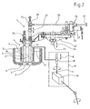
- FIG. 2 shows the device according to FIG. 1 in another working position, FIG.
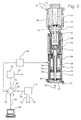
- 3 is a longitudinal section through a press die mechanism with closed preform and associated block diagram for determining a mass difference,
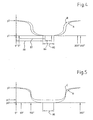
- 4 shows two different movement profiles for a plunger holder,
- 5 shows two further different movement profiles for a plunger holder,
- Fig. 6 shows the position of two plunger strokes over several feeder cycles.
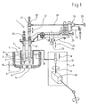
Die Vorrichtung zur Regelung der Glastropfenmasse gemäß Fig. 1 ist mit 1 bezeichnet. Die Vorrichtung 1 weist zwei Plunger 2 und 2' auf. Die Plunger 2, 2' sind in einem Speiserkopf 3 eines Speisers 4 angeordnet. Der Speiserkopf 3 besitzt einen zweifachen Tropfenauslass, der durch zwei Durchbrechungen 5 und 5' in einem Tropfring 6 gebildet ist. Ferner weist der Speiserkopf 3 ein Drosselrohr 7 auf, das die beiden Plunger 2, 2' umgibt. Das Drosselrohr 7 ist in an sich bekannter Weise in seiner als Stellgröße dienenden axialen Position gemäß Doppelpfeil 8 veränderbar. Ein Antrieb 9 des Drosselrohrs 7 ist in Fig. 1 schematisiert und nur teilweise gezeigt. Zur Verstellung der vertikalen Position des Drosselrohrs 7 ist ein nicht gezeigter Motor vorgesehen, der über ein Winkelgetriebe 10 eine Spindel 11 antreibt. Die Spindel 11 wirkt mit einer mit dem Drosselrohr 7 verbundenen Spindelmutter 12 zusammen. Weiterhin kann ein Mechanismus (nicht gezeigt) vorgesehen sein, um das Drosselrohr 7 zur symmetrischen Anordnung um den zweifachen Tropfenauslass 5, 5' herum waagerecht verstellen zu können. Durch die vertikale Verstellung gemäß Doppelpfeil 8 wird ein Spalt 15 zwischen einem unteren Ende des Drosselrohrs 7 und dem Tropfring 6 eingestellt.The device for controlling the glass drop mass according to FIG. 1 is denoted by 1. The
In dem Speiserkopf 3 befindet sich schmelzflüssiges Glas. Der Glasstand außerhalb des Drosselrohrs 7 ist mit 17 bezeichnet, während der Glasstand innerhalb des Drosselrohrs mit 18 bezeichnet ist. Der Glasstand 18 hängt vom Glasstand 17 und von der Größe des Spalts 15 ab. Der Glasstand 18 bestimmt letztendlich das aus den Durchbrechungen 5, 5' pro Zeiteinheit bzw. pro Feederzyklus austretende Glasvolumen. Durch eine vertikale Verstellung des Drosselrohrs 7 gemäß Doppelpfeil 8 kann somit insbesondere eine Änderung des Glasstands 17 oder eine Viskositätsänderung des schmelzflüssigen Glases über einen Zeitraum ausgeglichen werden, der gegenüber der Dauer eines Feederzyklus relativ lang ist.In the
Die Plunger 2, 2' sind jeweils mit Befestigungsmitteln 20 bzw. 21 an einem Plungerhalter 22 befestigt. Der Plungerhalter 22 ist an einer Tragsäule 23 befestigt, die senkrecht auf und ab bewegbar ist, wie durch Doppelpfeil 24 angedeutet ist. Bei dem Antriebsmechanismus für die Tragsäule 23, der nicht gezeigt ist, kann es sich beispielsweise um den Antriebsmechanismus gemäß der
Während die Höhe des Plungers 2 relativ zu dem Plungerhalter 22 fest ist, kann die Höhe des Plungers 2' relativ zu dem Plungerhalter 22 durch eine Höhenverstelleinrichtung 26 verändert werden. Die Höhenverstelleinrichtung 26 weist eine Motor-Getriebe-Einheit 27 auf, welche eine Welle 28 antreibt. Ein Handrad 29 erlaubt ein manuelles Drehen der Welle 28. Die Welle 28 wirkt über ein Schneckengetriebe 30 auf ein Führungselement 31 der Befestigungsmittel 21, um den Plunger 2' gemäß Doppelpfeil 32 zu bewegen.While the height of the
In Fig. 2 sind beide Plunger 2,2' in einer unteren Endstellung gezeigt. Hierbei handelt es sich um eine untere Endstellung, die zu einem bestimmten Bewegungsprofil einer Reihe von verschiedenen Bewegungsprofilen der Plunger 2, 2' gehört.In Fig. 2, both plungers are shown 2,2 'in a lower end position. This is a lower end position, which belongs to a certain movement profile of a number of different movement profiles of the
Fig. 3 zeigt eine Vorformstation 35 einer Sektion 36 einer I.S.-Glasformmaschine. Die Vorformstation 35 weist einen Vorformboden 37, Vorformhälften 38 und 39, Mündungswerkzeughälften 40 und 41 und einen Pressstempel 42 auf. Der Pressstempel 42 ist in an sich bekannter Weise am oberen Ende einer Kolbenstange 43 eines Kolbens 44 befestigt. Der Kolben 44 ist in einem Zylinder 45 einer Kolben-Zylinder-Einheit 46 verschiebbar. Unterhalb des Kolbens 44 befindet sich ein Vorschubraum 47 und oberhalb des Kolbens 44 ein Rückzugsraum 48. Der Kolben 44 trägt einen Betätigungsring 49 für einen Pressstempelstellungssensor 50, der in diesem Fall gemäß der
Der Pressstempel 42 wird durch einen zu dem Zylinder 45 koaxialen Führungszylinder 53 geführt. In dem Führungszylinder 53 ist außerdem eine Feder 54 angeordnet, die bei entlüftetem Vorschubraum 47 und entlüftetem Rückzugsraum 48 den Pressstempel 42 in seine in Fig. 3 gezeigte axiale Ladestellung bewegt. In dieser Ladestellung taucht eine obere Spitze des Pressstempels 42 gerade in einen Mündungsbereich einer Vorformausnehmung 56 ein. In der Ladestellung ist zunächst der Vorformboden 37 entfernt, so dass von oben her ein Glastropfen in die Vorformausnehmung 56 und auf die Spitze des Pressstempels 42 fallen kann.The
Die Kolbenstange 43 ist hohl ausgebildet und nimmt ein an einem Boden 57 befestigtes Kühlluftrohr 58 auf. Dem Kühlluftrohr 58 wird Kühlluft für den Pressstempel 42 in Richtung eines Pfeils 59 zugeführt.The
Ein Anschluss zur Be- und Entlüftung des Vorschubraums 47 ist mit 60, ein Anschluss zur Be- und Entlüftung des Rückzugsraums 48 mit 61 bezeichnet. Weitere Mittel zur Be- und Entlüftung des Vorschubraums 47 und des Rückzugsraums 48 zur Ausführung eines Presszyklus des Pressstempels 42 sind nicht dargestellt. Insbesondere kann es sich dabei um Mittel gemäß der deutschen Patentanmeldung 103 16 600.9 handeln.A connection for ventilation of the
Der Pressstempelstellungssensor 50 ist über eine SignalverstärkeriSignalauswerteeinheit 65 mit einem Signaleingang 66 einer in Software realisierten Regelschaltung 67 verbunden. Die Regelschaltung 67 ist ferner über eine Leitung 68 bidirektional mit einer Eingabe-/Ausgabeeinheit 69 verbunden. Ein Signalausgang 70 der Regelschaltung 67 ist durch eine Leitung 72 mit einer gemeinsamen Antriebssteuerung 71 für den Plungerhalter 22 und die Höhenverstelleinrichtung 26 verbunden.The press
Mittels des Pressstempelsensors 50 wird ein Stellungssignal erzeugt, das eine Aussage über die Größe der maximalen Eindringtiefe des Pressstempels 42 in das Formwerkzeug liefert. Je größer die maximale Eindringtiefe ist, desto geringer ist die in die Vorformausnehmung 56 gelangte Tropfenmasse. Die gemessene Pressstempelendstellung wird von der Signalverstärker -/ Signalauswerteeinheit 65 an die Regelschaltung 67 gegeben. Die Regelschaltung 67 vergleicht die gemessene Pressstempelendstellung mit einem Sollwert für die Pressstempelendstellung, welcher der Regelschaltung 67 über die Eingabe-/Ausgabeeinheit 69 eingegeben worden ist. Die Sollwerte der Pressstempelendstellung sind für jede Vorformstation 35 der I.S.-Glasformmaschine getrennt einstellbar.By means of the
Die daraus erhaltene Abweichung zwischen dem Sollwert und dem Istwert der Pressstempelendstellung wird unter Berücksichtigung der bekannten Querschnittsfläche des Pressstempels 42 in eine Massendifferenz bzw. in eine Gewichtsdifferenz umgerechnet. Diese Massendifferenz wird über den Signalausgang 70 an die Antriebssteuerung 71 gegeben. In der Antriebssteuerung 71 wird ein realer Mittelwert der Massendifferenzen aller Tropfen eines Maschinenzyklus gebildet. Durch eine schrittweise Veränderung der axialen Position des Drosselrohrs 7, vorzugsweise jeweils zwischen zwei Maschinenzyklen, wird dafür gesorgt, dass dieser reale Mittelwert zumindest nahezu den Wert null annimmt. Wenn dies erreicht ist, weisen die Tropfen eines Maschinenzyklus in der Summe betrachtet die gewünschte Gesamtmasse auf, jedoch werden die einzelnen Tropfen noch nicht den Massen-Sollwert aufweisen. Um dies zu erreichen, werden die ermittelten Massendifferenzen der Einzeltropfen nach einer Skalierung verwendet, um einen oder mehrere Parameter des Bewegungsprofils desjenigen Plungers zu verändern, der den Tropfen erzeugt hat. Die Skalierung erfolgt dergestalt, dass die skalierten Massendifferenzen bei vorzeichenrichtiger Addition über einen Maschinenzyklus einen "fiktiven" Mittelwert von null ergeben. Auf diese Weise sind der Drosselrohr-Regelkreis und der Plunger-Regelkreis quasi in Reihe geschaltet.The deviation between the setpoint value and the actual value of the ram end position resulting therefrom is converted into a mass difference or a weight difference taking into account the known cross-sectional area of the
Die Antriebssteuerung 71 ist über eine Signalleitung 74 mit einem nicht gezeigten Motor des Antriebsmechanismus für die Tragsäule 23 verbunden. Ferner ist die Antriebssteuerung 71 über eine Signalleitung 75 mit der Schrittmotor-Getriebe-Einheit 27 der auf den Plunger 2' wirkenden Höhenverstelleinrichtung 26 verbunden.The
Ein weiterer Signalausgang 76 der Regelschaltung 67 ist mit einer Drosselrohr-Antriebssteuerung 77 verbunden. Eine Signalleitung 78 führt von der Drosselrohr-Antriebssteuerung 77 zu dem Antrieb 9 des Drosselrohrs 7.Another
Es müssen so viele Plunger-Bewegungsprofile vorgesehen werden, wie es Vorformstationen 35 in der I.S. Glasformmaschine gibt. Da die Vorrichtung 1 gemäß Fig. 1 bzw. 2 einen Speiserkopf 3 mit einem zweifachen Tropfenauslass aufweist, ist vorgesehen, dass in jede Sektion der I.S.-Glasformmaschine gleichzeitig zwei Tropfen gelangen, die jeweils in einer von zwei Vorformstationen 35 der jeweiligen Sektion verarbeitet werden. Zum Beispiel kann es sich bei der 1.S.-Glasformmaschine um eine 8-DG-Maschine handeln, welche also acht Sektionen aufweist und innerhalb eines Maschinenzyklus sechzehn Tropfen verarbeitet. Weiterhin kann vorgesehen sein, dass die beiden Tropfen, die gleichzeitig in eine Sektion gelangen, dieselbe Masse aufweisen sollen. Ein relativ einfaches herzustellendes Sortiment kann zwei unterschiedliche Typen von Hohlglasbehältem aufweisen, nämlich einen leichten Hohlglasbehälter und einen schweren Hohlglasbehälter. In diesem Fall kann vorgesehen sein, dass über die Zündfolge eines Maschinenzyklus jeweils auf einen schweren Tropfen ein leichter folgt, auf diesen wieder ein schwerer u.s.w.As many plunger motion profiles must be provided as there are
Bei der obigen Ausführungsform des Verfahrens bzw. der Vorrichtung sind in der Antriebssteuerung 71 acht Datensätze für acht Bewegungsprofile des Plungerhalters 22, also für die acht Feederzyklen eines Maschinenzyklus, abgespeichert. Da alternierend jedoch nur zwei unterschiedliche Tropfenmassen erzeugt werden sollen, werden nach Abschluss eines Einregelungsvorgangs, der sich in der Regel nur über wenige Maschinenzyklen erstreckt, jeweils vier Bewegungsprofile bzw. Datensätze identisch sein, so dass der Plungerhalter 22 alternierend immer nur zwei Bewegungsabläufe ausführt.In the above embodiment of the method or the device, eight data sets for eight movement profiles of the
In Fig. 4 sind diese beiden Plungerhalter-Bewegungsprofile mit A und B bezeichnet. Auf der Abszisse ist der Ablauf eines Feederzyklus aufgetragen, wobei der Beginn und das Ende eines Feederzyklus mit 0° bzw. 360° bezeichnet sind. Auf der Ordinate ist die vertikale Position des Plungerhalters 22 aufgetragen, wobei mit y1 eine untere Endstellung des Plungerhalters 22 und mit y2 eine obere Endstellung des Plungerhalters 22 bezeichnet sind. Da die Zeitdauer eines Feederzyklus vorgegeben ist, stellen die Bewegungsprofile A und B Ort und Zeit des Plungerhalters 22 über einen Feederzyklus dar.In Fig. 4, these two plunger holder movement profiles are designated A and B. The abscissa shows the course of a feeder cycle, the beginning and the end of a feeder cycle being denoted by 0 ° and 360 °, respectively. The vertical position of the
Das Bewegungsprofil A weist in der unteren Endstellung y1 des Plungerhalters 22 eine Stillstandsdauer 85 auf, die länger ist als eine entsprechende Stillstandsdauer 86 des Bewegungsprofils B. Da eine längere Stillstandsdauer eines Plungers in seiner unteren Endstellung eine geringere Tropfenmasse bewirkt, ist das Bewegungsprofil A für die Sektionen der 1.S.-Glasformmaschine vorgesehen, die zur Herstellung der leichteren Hohlglasbehälter verwendet werden, während das Bewegungsprofil B zur Erzeugung der Tropfen für die schwereren Hohlglasbehälter vorgesehen ist. Ferner weist das Bewegungsprofil A im Vergleich zu dem Bewegungsprofil B eine kürzere Stillstandsdauer in der oberen Endstellung y2 auf. Gemäß Bewegungsprofil B bleibt der Plungerhalter 22 etwa zwischen 355° und 5° in seiner oberen Endstellung y2. Die Zeitdauer 87 der Abwärtsbewegung gemäß Bewegungsprofil B ist jedoch nahezu gleich der Zeitdauer 88 der Abwärtsbewegung gemäß Bewegungsprofil A. Entsprechendes gilt für die Aufwärtsbewegungen gemäß den Bewegungsprofilen A und B, da die Abwärts- und Aufwärtsbewegungen des Bewegungsprofils A bzw. B jeweils symmetrisch zueinander sind. Bei dem Bewegungsprofil A ist die Stillständsdauer 85 in der unteren Endstellung y1 länger als die nahezu den Wert null aufweisende Stillstandsdauer in der oberen Endstellung y2.In the lower end position y1 of the
Die beiden Bewegungsprofile A und B werden durch schrittweise Näherung ausgehend von jeweils einer Anfangsbewegung für das Bewegungsprofil A bzw. Bewegungsprofil B erreicht, indem nach Durchlaufen eines Maschinenzyklus die Bestimmung der Massendifferenz für jeden innerhalb des Maschinenzyklus erzeugten Tropfen durchgeführt wird und eine entsprechende Veränderung des zugehörigen Bewegungsprofils des Plungerhalters 22 vorgenommen wird. Dieses Näherungsverfahren ist abgeschlossen, wenn die Massen-Istwerte ausreichend nahe an dem jeweiligen Massen-Sollwert liegen, also die gemessene Massendifferenz einen vorgegebenen Schwellenwert nicht überschreitet. Das Näherungsverfahren benötigt in der Regel nur einige Maschinenzyklen.The two motion profiles A and B are achieved by stepwise approximation, starting from in each case an initial movement for the movement profile A or movement profile B, by determining the mass difference for each drop generated within the machine cycle after passing through a machine cycle and a corresponding change of the associated motion profile the
In Fig. 5 sind zwei weitere Bewegungsprofile C und D des Plungerhalters 22 dargestellt, die ebenfalls für ein Sortiment, wie es in Zusammenhang mit Fig. 4 beschrieben ist, verwendet werden sollen. Die Bewegungsprofile C und D unterscheiden sich von den Bewegungsprofilen A und B vor allem dadurch, dass sie unterschiedliche Hübe des Plungerhalters 22 beschreiben. Der Hub des Bewegungsprofils C ist der Abstand zwischen einer unteren Endstellung yc1 und einer oberen Endstellung y2 des Plungerhalters 22. Während die obere Endstellung des Plungerhalters 22 gemäß dem Bewegungsprofil D ebenfalls y2 ist, liegt eine untere Endstellung yd1 tiefer als bei dem Bewegungsprofil C. Das Bewegungsprofil C bewirkt die Ausgabe der schwereren Tropfen aus dem Speiserkopf 3, das Bewegungsprofil D hingegen die Ausgabe der leichteren Tropfen. Denn durch die jeweilige untere Endstellung yc1 bzw. yd1 wird der freie Querschnitt der Durchbrechungen 5, 5' beeinflusst.In Fig. 5, two further movement profiles C and D of the
Eine Stillstandsdauer 95 des Plungerhalters 22 in seiner unteren Endstellung yc1 bzw. yd1 ist bei den beiden Bewegungsprofilen C und D gleich. Ferner unterscheidet sich das Bewegungsprofil C durch die Geschwindigkeitsstruktur der Abwärts- und Aufwärtsbewegung von dem Bewegungsprofil D. Beispielsweise zeigt sich diese unterschiedliche Geschwindigkeitsstrukur zwischen 60° und 150° sowie entsprechend in den dazu symmetrischen Aufwärtsbewegungen der Bewegungsprofile C und D.A
Die beschriebenen Parameter oder auch weitere Parameter der Plungerhalter-Bewegungsprofile können zur Erzeugung einer gewünschten Tropfengröße bzw. Tropfenkontur verändert werden. Insbesondere kann die Geschwindigkeit, mit der der Plungerträger 22 nahe seiner unteren Endstellung abwärts- oder aufwärts bewegt wird, variiert werden. Bei der Aufwärtsbewegung wird bei sehr zähflüssigem Glas ein gewisser Teil des Glases wieder mit zurückgezogen.The described parameters or other parameters of the plunger holder movement profiles can be changed to produce a desired drop size or drop contour. In particular, the speed at which the
Während in den oben beschriebenen Situationen gemäß Fig. 4 und Fig. 5 ein Sortiment mit nur zwei unterschiedlichen Artikelgewichten mit alternierender Reihenfolge in der Zündfolge hergestellt werden soll, kann z.B. auch vorgesehen sein, dass in dem Sortiment zwar nur zwei unterschiedliche Artikelgewichte vorgesehen sind, jedoch in einer Folge von acht Feederzyklen einer 8-DG-Maschine zunächst zwei schwere Tropfenpaare (z.B. 168 g pro Tropfen), danach fünf leichte Tropfenpaare (z.B. 160 g pro Tropfen) und anschließend wieder ein schweres Tropfenpaar erzeugt werden sollen. Die Sequenz der fünf leichten Tropfenpaare in Folge bewirkt, dass der Glasstand 18 im Inneren des Drosselrohrs 7 während der Dauer dieser Sequenz zunehmend steigt, da weniger Glas abfließt. Ohne eine entsprechende Regelung hätten die Tropfenpaare innerhalb dieser Leicht-Sequenz unterschiedliche Massen. Entsprechendes würde für eine Schwer-Sequenz gelten. Mit dem Verfahren bzw. der Vorrichtung gemäß der Erfindung kann in kurzer Zeit eine Regelung der gewünschten Massen der Tropfen erzeugt werden, indem für jeden erzeugten Tropfen ein zugehöriges Plunger-Bewegungsprofil eingestellt wird.While in the situations described above according to FIG. 4 and FIG. 5, an assortment with only two different article weights with alternating order in the firing order is to be produced, e.g. may also be provided that in the assortment, although only two different article weights are provided, but in a series of eight Feederzyklen an 8-DG machine initially two heavy droplet pairs (eg 168 g per drop), then five light droplet pairs (eg 160 g per Drop) and then again a heavy pair of drops to be generated. The sequence of the five light droplet pairs in sequence causes the
Es kann sein, dass die Bewegungsprofile der Plunger 2, 2' relativ betrachtet mit dem Bewegungsprofil des Plungerhalters 22 übereinstimmen. Dies ist dann der Fall, wenn eine geregelte Einstellung des Plungers 2' relativ zu dem Plunger 2 nicht vorgesehen ist. Eine solche Einstellung des Plungers 2' kann jedoch aufgrund unerwünschter geringfügiger Unterschiede zwischen den Durchbrechungen 5, 5' erforderlich sein, um zu erreichen, dass die beiden aus den Durchbrechungen 5, 5' ausgegebenen und in dieselbe Sektion gelangenden Tropfen gleich groß sind. In der Regel wird dies gewünscht sein. Wenn es dazu erforderlich ist, wird der Plunger 2' durch die Höhenverstelleinrichtung 26, die über die Antriebssteuerung 71 angesteuert wird, von Feederzyklus zu Feederzyklus verstellt. Diese Bewegung der Befestigungsmittel 21 bzw. zusätzliche Bewegung des Plungers 2' wird der Bewegung des Plungerhalters 22 überlagert, so dass sich daraus die resultierende Bewegung des Plungers 2' ergibt. In dem oben beschriebenen Beispiel einer 8-DG-Maschine werden dazu neben den acht Bewegungsprofil-Datensätzen für den Plungerhalter 22 weitere acht Bewegungsprofil-Datensätze für die Höhenverstelleinrichtung 26 in der Antriebssteuerung 71 gespeichert.It may be that the movement profiles of the
In Fig. 6 sind die Hübe der beiden Plunger 2 und 2' über drei aufeinander folgende Feederzyklen (Abszisse) dargestellt. Auf der Ordinate h ist die relative Höhe des jeweiligen unteren Endes des Plungers 2 bzw. 2' über dem Tropfring 6 dargestellt. Mit den Balken 98, 98' und 98" sind die Hübe des Plungers 2 und ihre Lage während drei aufeinander folgender Feederzyklen dargestellt. Ferner sind die Hübe des Plungers 2' und ihre Lage für die drei Feederzyklen durch Balken 99, 99' und 99" dargestellt. Die Plungerhübe 98 und 99 sind gleich, d.h. die maximalen Auslenkungen der Plunger 2 und 2' sind gleich, weil die Plunger 2, 2' an demselben Plungerhalter 22 befestigt sind. Jedoch ist die Lage der Plungerhübe 98 und 99 verschieden, um geringfügige Größenunterschiede der Durchbrechungen 5, 5' so auszugleichen, dass in dem Feederzyklus ein Paar gleich großer Tropfen erzeugt wird. Dazu ist der Plunger 2', anders als in den Fig. 1 und 2 dargestellt, etwas tiefer als der Plunger 2 an dem Plungerhalter 22 befestigt ist. Die Plungerhübe 98 und 99 sind somit ausschließlich durch die Hubbewegung des Plungerhalters 22 bestimmt.In Fig. 6, the strokes of the two
Während des zweiten dargestellten Feederzyklus weisen die Plunger 2 und 2' die Hübe 98' und 99' auf. Diese sind gegenüber dem ersten gezeigten Feederzyklus unverändert, ebenso ihre Lage, da in dem in Fig. 6 gezeigten Beispiel das Näherungsverfahren bereits abgeschlossen ist, sich also ein gewünschtes Gleichgewicht in Bezug auf die Tropfenmassen eingestellt hat, und vorgesehen ist, während des ersten und des zweiten gezeigten Feederzyklus gleiche Tropfenmassen zu erzeugen.During the second illustrated feeder cycle,
Für den dritten gezeigten Feederzyklus ist hingegen vorgesehen, eine größere Tropfenmasse zu erzeugen. Dazu werden kleinere Plungerhübe 98" und 99" erzeugt, indem der Plungerhalter 22 gemäß einem zugehörigen Datensatz einen entsprechend verringerten Hub durchführt. Dabei befinden sich die unteren Endstellungen der Plunger 2 und 2' in einem größeren Abstand zu den Durchbrechungen 5 bzw. 5' als in den beiden vorherigen Feederzyklen. Die genannten geringfügigen Unterschiede der Durchbrechungen 5, 5' machen es nun in dem dritten gezeigten Feederzyklus erforderlich, den Plunger 2' in seiner vertikalen Position nach oben zu verschieben, um auch in dem dritten gezeigten Feederzyklus ein Paar gleich großer Tropfen zu erzeugen. Diese Verschiebung des Plungers 2' wird durch eine entsprechende Anpassung des Datensatzes mittels der Höhenverstelleinrichtung 26 bewirkt, und zwar vorzugsweise dann, wenn sich der Plunger 2' im Bereich seiner oberen Endstellung befindet. Die Dynamik der Veränderung der Hublage des Plungers 2' ist in Fig. 6 der Übersichtlichkeit halber nicht dargestellt.By contrast, it is provided for the third feeder cycle shown to produce a larger drop mass. For this purpose, smaller plunger strokes 98 "and 99" are generated by the
Claims (17)
- Method of controlling the glass gob mass in the production of hollow glass containers by means of a glass forming machine (36), wherein at least one plunger (2,2') is disposed in a feeder head (3) of a feeder (4) and in order to move the at least one plunger (2,2') vertically upwards and downwards a movement profile (A,B,C,D) is provided which can be changed in order to influence the discharge of molten glass from the feeder head (3),
characterized in that the glass forming machine is an IS (Individual Section) glass forming machine (36) and for the simultaneous production of an assortment of hollow glass containers of a different weight a changeable movement profile (A,B,C,D) for each plunger (2,2') is provided for each section (36) of the IS glass forming machine,
a mass reference value difference is determined from a mass reference desired value and a measured mass reference actual value on the basis of at least one of consecutive gobs for each preform station (35) of each section (36),
in dependence upon the determined mass reference value difference for each preform station (35) the associated plunger movement profile (A,B,C,D) is changed in such a manner that by virtue of subsequent repetition of the determination of the mass reference value difference with subsequent change to the movement profile (A,B,C,D) the mass reference actual value is approximated stepwise to the mass reference desired value. - Method as claimed in claim 1,
characterized in that after each completed machine cycle a check is carried out for each preform station (35) to verify whether the mass reference value difference is above a threshold value and if this is the case the plunger movement profile (A,B,C,D) is adapted for the preform station (35). - Method as claimed in claim 1 or 2,
characterized in that the standstill period (85,86) of the plunger (2,2') is changed in its lower (y1;yc1,yd1) and/or upper (y2) end position. - Method as claimed in any one of the preceding claims,
characterized in that the duration (87,88) of the downwards and/or upwards movement of the plunger (2,2') is changed. - Method as claimed in any one of the preceding claims,
characterized in that the speed structure of the downwards and/or upwards movement of the plunger (2,2') is changed. - Method as claimed in any one of the preceding claims,
characterized in that the plunger stroke (98,98',98",99,99',99") is changed. - Method as claimed in any one of the preceding claims,
characterized in that the position (98,98',98",99,99',99") of the plunger stroke relative to an orifice ring (6) of the feeder head (3) is changed. - Method as claimed in any one of the preceding claims,
characterized in that at least one substantially horizontally extending plunger holder (22) is provided and each plunger movement profile is determined by a data record for an associated movement profile (A,B,C,D) of the plunger holder (22). - Method as claimed in claim 8,
characterized in that in the presence of several plungers (2,2') for each section (36), in addition to the respective data record for the plunger holder (22) or the data records for the plunger holders (22), except for a first plunger (2), for each of the plungers (2') a data record for a profile (99,99',99") is provided to move the plunger (2') relative to its plunger holder (22). - Method as claimed in any one of the preceding claims,
characterized in that if, in addition, the axial position of a restrictor pipe (7) of the feeder head (3) is regulated in order to compensate for the effects of changes in the viscosity of the molten glass or changes in the glass level (17, 18) in the feeder head (3) upon the mass of the glass containers to be produced, a real mean value is formed from the mass reference value differences of all gobs of a machine cycle and this mean value is approximated to the value zero by changing the axial position of the restrictor pipe (7) between two respective cycles and furthermore, the mass reference value differences are scaled in such a manner that a fictitious mean value of zero is produced from the scaled mass reference value differences and the change in the plunger movement profiles (A,B,C,D) is performed on the basis of the scaled mass reference value differences. - Device (1) for controlling the glass gob mass in the production of hollow glass containers by means of a glass forming machine (36), comprising at least one plunger (2,2'), which is disposed in a feeder head (3) of a feeder (4), and means (22,23,26) for moving the at least one plunger (2,2') upwards and downwards, wherein a movement profile (A,B,C,D) for the plunger movement is stored in a control unit (71) of the device (1), said movement profile being changeable in order to influence the discharge of molten glass from the feeder head (3),
characterized in that the glass forming machine is an IS (Individual Section) glass forming machine (36) and for the simultaneous production of an assortment of hollow glass containers of a different weight a changeable movement profile (A,B,C,D) for each plunger (2,2') can be stored in the control unit (71) for each section (36) of the IS glass forming machine,
the device (1) comprises means (67) to determine a mass reference value difference from a mass reference desired value and a measured mass reference actual value on the basis of at least one of consecutive gobs for each preform station (35) of each section (36),
and the control unit (71) is connected via a data line (72) to the means (67) for determining the mass reference value difference and is designed, in dependence upon the determined mass reference value difference for each preform station (35), to change the associated plunger movement profile (A,B,C,D) such that by virtue of subsequent repetition of the determination of the mass reference value difference with subsequent change to the movement profile (A,B,C,D) the mass reference actual value is approximated stepwise to the mass reference desired value. - Device as claimed in claim 11,
characterized in that the device (1) is designed, after each completed machine cycle to carry out a check for each preform station (35) to verify whether the mass reference value difference is above a threshold value and if this is the case, to adapt the plunger movement profile (A,B,C,D) for the preform station (35). - Device as claimed in claim 11 or 12,
characterized in that the device (1) is designed to change the plunger movement profiles (A,B,C,D), by changing one parameter or several parameters in combination with each other from the group consisting of standstill period (85,86) of the respective plunger (2,2') in its lower (y1;yc1,yd1) and/or upper (y2) end position, duration (87,88) of the downwards and/or upwards movement of the plunger (2,2'), speed structure of the downwards and/or upwards movement of the plunger (2,2'), plunger stroke (98,98',98",99,99',99") and position (98,98',98",99,99',99") of the plunger stroke relative to an orifice ring (6) of the feeder head (3). - Device as claimed in any one of claims 11 to 13,
characterized in that the device (1) comprises at least one substantially horizontally extending plunger holder (22) and each plunger movement profile is determined by a data record, which is stored in the control unit (71), for an associated movement profile (A,B,C,D) of the plunger holder (22). - Device as claimed in claim 14,
characterized in that all of the plungers (2,2') are jointly attached to a plunger holder (22) and the control unit is a drive controller (71) of the plunger holder (22). - Device as claimed in claim 14 or 15,
characterized in that the device (1) comprises several plungers (2, 2') and for each section (36) in addition to the respective data record for the plunger holder (22) or the data records for the plunger holders (22), except for a first plunger (2), for each of the plungers (2') a data record for a profile (99,99',99") to move the plunger (2') relative to its plunger holder (22) by means of a height adjusting device (26) can be stored in an associated drive controller (71). - Device as claimed in any one of claims 11 to 16,
characterized in that if, in addition, a control circuit for the axial position of a restrictor pipe (7) of the feeder head (3) is provided for the purpose of compensating for the effects of changes in the viscosity of the molten glass or of changes in the glass level in the feeder head (3) upon the mass of the glass containers to be produced, the device (1) is designed to form a real mean value from the mass reference value differences of all gobs of a machine cycle and to approximate this mean value to the value zero by changing the axial position of the restrictor pipe (7) between two respective machine cycles and furthermore to scale the mass reference value difference in such a manner that a fictitious mean value of zero is produced from the scaled mass reference value differences, and to perform the change in the plunger movement profiles (A,B,C,D) on the basis of the scaled mass reference value differences.
Applications Claiming Priority (3)
| Application Number | Priority Date | Filing Date | Title |
|---|---|---|---|
| DE102004011647 | 2004-03-10 | ||
| DE102004011647A DE102004011647A1 (en) | 2004-03-10 | 2004-03-10 | Method and device for controlling glass drop mass in the production of hollow glass containers |
| PCT/EP2005/002302 WO2005087670A1 (en) | 2004-03-10 | 2005-03-04 | Method and device for regulating the glass gob during the production of hollow glass containers |
Publications (2)
| Publication Number | Publication Date |
|---|---|
| EP1599424A1 EP1599424A1 (en) | 2005-11-30 |
| EP1599424B1 true EP1599424B1 (en) | 2007-11-07 |
Family
ID=34895139
Family Applications (1)
| Application Number | Title | Priority Date | Filing Date |
|---|---|---|---|
| EP05715733A Active EP1599424B1 (en) | 2004-03-10 | 2005-03-04 | Method and device for regulating the glass gob during the production of hollow glass containers |
Country Status (7)
| Country | Link |
|---|---|
| US (1) | US20060213226A1 (en) |
| EP (1) | EP1599424B1 (en) |
| AT (1) | ATE377576T1 (en) |
| BR (1) | BRPI0508636B1 (en) |
| DE (2) | DE102004011647A1 (en) |
| MX (1) | MXPA06009303A (en) |
| WO (1) | WO2005087670A1 (en) |
Families Citing this family (5)
| Publication number | Priority date | Publication date | Assignee | Title |
|---|---|---|---|---|
| EP2610223B1 (en) * | 2011-12-27 | 2017-09-27 | BDF Industries S.p.A. | Method and device for controlling the amount of molten glass to be dispensed |
| CN106237893B (en) * | 2016-09-28 | 2019-02-15 | 山东三金玻璃机械有限公司 | A kind of feeding machine even distributor |
| US10865132B2 (en) * | 2018-08-14 | 2020-12-15 | Emhart Glass | Apparatus and method to control gob weight, length and/or shape |
| IT201800009629A1 (en) * | 2018-10-19 | 2020-04-19 | Bottero Spa | PUNCH UNIT FOR THE FORMING OF MOLTEN GLASS CORDS |
| FR3094978B1 (en) * | 2019-04-11 | 2021-04-23 | Soc Europeenne Des Produits Refractaires | FOREST BOWL ASSEMBLY OF A GLASS DISTRIBUTION CHANNEL |
Family Cites Families (18)
| Publication number | Priority date | Publication date | Assignee | Title |
|---|---|---|---|---|
| US1732711A (en) * | 1920-05-04 | 1929-10-22 | Westinghouse Electric & Mfg Co | Control system |
| US1955869A (en) * | 1931-12-11 | 1934-04-24 | Wood John Thomas | Apparatus for feeding predetermined different weights of molten glass |
| US4551163A (en) * | 1984-06-04 | 1985-11-05 | Emhart Industries, Inc. | Electronic glass feeder plunger operating mechanism |
| US4682998A (en) * | 1985-09-09 | 1987-07-28 | Vitro Tec Fideicomiso | Electronic system for automatically controlling the weight of glass gobs in a molten glass feeder |
| JPH02267125A (en) * | 1989-04-07 | 1990-10-31 | Hoya Corp | Device for forming glass product |
| EP0612698B1 (en) * | 1993-02-25 | 1999-09-15 | Owens-Brockway Glass Container Inc. | Multiple orifice glass feed system |
| US5885317A (en) * | 1993-02-25 | 1999-03-23 | Owens-Brockway Glass Container Inc. | Multiple orifice glass feed system |
| DE9404164U1 (en) * | 1993-05-27 | 1994-05-19 | Heye Hermann Fa | Position transducer for verifying the position of a press ram |
| IT1267393B1 (en) * | 1994-02-18 | 1997-02-05 | Bottero Spa | PLANT FOR THE FORMING OF GLASS ITEMS. |
| US5660610A (en) * | 1994-10-24 | 1997-08-26 | Owens-Brockway Glass Container Inc. | Remotely adjustable glass feeder needle assembly |
| JPH08333121A (en) * | 1995-05-31 | 1996-12-17 | Toshiba Glass Co Ltd | Control of gob weight and apparatus therefor |
| US5779749A (en) * | 1997-04-21 | 1998-07-14 | Owens-Brockway Glass Container Inc. | Generation of needle motion profile in an individual section glassware forming system |
| JPH1160247A (en) * | 1997-08-08 | 1999-03-02 | Toyo Glass Kikai Kk | Gob weight controlling device |
| ATE309967T1 (en) * | 2001-06-12 | 2005-12-15 | Glas Heinz Gmbh | METHOD AND DEVICE FOR THE SIMULTANEOUS PRODUCTION OF GLASS PRODUCTS OF DIFFERENT DIMENSIONS |
| DE10133019C1 (en) * | 2001-07-06 | 2003-01-30 | Hermann Heye I Ins Fa | Method and device for determining the mass of a free-falling, molten glass drop |
| DE10254654A1 (en) * | 2002-11-22 | 2004-06-09 | Heinz-Glas Gmbh | Device and method for processing glass items of different masses and feeding device |
| DE10316600A1 (en) * | 2003-04-11 | 2004-11-04 | Heye International Gmbh | Method and device for driving a press ram of a glass forming machine |
| DE20316501U1 (en) * | 2003-10-25 | 2003-12-24 | Heye International Gmbh | Device for moving plungers up and down in a feeder head for a glass molding machine |
-
2004
- 2004-03-10 DE DE102004011647A patent/DE102004011647A1/en not_active Ceased
-
2005
- 2005-03-04 DE DE502005001858T patent/DE502005001858D1/en active Active
- 2005-03-04 BR BRPI0508636-1A patent/BRPI0508636B1/en not_active IP Right Cessation
- 2005-03-04 AT AT05715733T patent/ATE377576T1/en not_active IP Right Cessation
- 2005-03-04 EP EP05715733A patent/EP1599424B1/en active Active
- 2005-03-04 MX MXPA06009303A patent/MXPA06009303A/en active IP Right Grant
- 2005-03-04 US US10/564,899 patent/US20060213226A1/en not_active Abandoned
- 2005-03-04 WO PCT/EP2005/002302 patent/WO2005087670A1/en active IP Right Grant
Also Published As
| Publication number | Publication date |
|---|---|
| MXPA06009303A (en) | 2007-01-26 |
| EP1599424A1 (en) | 2005-11-30 |
| ATE377576T1 (en) | 2007-11-15 |
| DE102004011647A1 (en) | 2005-09-29 |
| BRPI0508636A (en) | 2007-08-07 |
| DE502005001858D1 (en) | 2007-12-20 |
| BRPI0508636B1 (en) | 2015-06-02 |
| WO2005087670A1 (en) | 2005-09-22 |
| US20060213226A1 (en) | 2006-09-28 |
Similar Documents
| Publication | Publication Date | Title |
|---|---|---|
| DE3208502C2 (en) | Glass forming machine | |
| EP1599424B1 (en) | Method and device for regulating the glass gob during the production of hollow glass containers | |
| DE3816273A1 (en) | METHOD FOR PRODUCING HOLLOW BODIES FROM THERMOPLASTIC PLASTIC | |
| EP0776752B1 (en) | Method of blow moulding and hollow thermoplastic articles | |
| DE3718961C2 (en) | ||
| EP1791440B3 (en) | Method and plant for the production of confectionery | |
| EP0732194B1 (en) | Method and apparatus for measuring and regulating the position of the slide in a high-speed cutting press | |
| EP0451239B1 (en) | Process for the production of hollow bodies from thermoplastic material | |
| EP2635493B1 (en) | Apparatus and method for the multiple filling of highly viscous materials | |
| EP1598321B1 (en) | Procedure and device for the production of divergent glass gob masses with the production of glass articles | |
| EP1466871B1 (en) | Process and apparatus to drive the plunger of a glass forming machine | |
| DE3232733C1 (en) | Method for controlling a machine for processing glass or other thermoplastic materials | |
| EP1897858B1 (en) | Device for shaping glass articles | |
| DE3620082C2 (en) | ||
| EP0263409B1 (en) | Method and apparatus for deforming a glass-job | |
| EP0685315B1 (en) | Method for extrusion blow moulding of hollow articles of thermoplastic material | |
| DE3446620C2 (en) | ||
| EP0813812B1 (en) | Dough treating device | |
| EP0013574B1 (en) | Molten glass gathering device | |
| DE3330076C2 (en) | ||
| DE447650C (en) | Method and device for controlling the outflow of glass from a container with molten glass | |
| DE19652308B4 (en) | Dynamic Iterative stamp control of the pressing process in multi-punching | |
| DE2417724A1 (en) | PROCESS FOR MANUFACTURING HOLLOW GLASS BODIES, PRODUCT MANUFACTURED BY THIS PROCESS AND DEVICE FOR CARRYING OUT THE PROCESS | |
| DE202009003560U1 (en) | Blowing head mechanism of a glass machine | |
| AT320380B (en) | Stop device for a press brake, guillotine shears or the like. |
Legal Events
| Date | Code | Title | Description |
|---|---|---|---|
| PUAI | Public reference made under article 153(3) epc to a published international application that has entered the european phase |
Free format text: ORIGINAL CODE: 0009012 |
|
| 17P | Request for examination filed |
Effective date: 20050721 |
|
| AK | Designated contracting states |
Kind code of ref document: A1 Designated state(s): AT BE BG CH CY CZ DE DK EE ES FI FR GB GR HU IE IS IT LI LT LU MC NL PL PT RO SE SI SK TR |
|
| AX | Request for extension of the european patent |
Extension state: AL BA HR LV MK YU |
|
| GRAP | Despatch of communication of intention to grant a patent |
Free format text: ORIGINAL CODE: EPIDOSNIGR1 |
|
| RBV | Designated contracting states (corrected) |
Designated state(s): AT BE BG CH CY CZ DE DK EE ES FI FR GB GR HU IE IS IT LI LT LU MC NL PL PT RO SE SI SK TR |
|
| GRAS | Grant fee paid |
Free format text: ORIGINAL CODE: EPIDOSNIGR3 |
|
| DAX | Request for extension of the european patent (deleted) | ||
| GRAA | (expected) grant |
Free format text: ORIGINAL CODE: 0009210 |
|
| AK | Designated contracting states |
Kind code of ref document: B1 Designated state(s): AT BE BG CH CY CZ DE DK EE ES FI FR GB GR HU IE IS IT LI LT LU MC NL PL PT RO SE SI SK TR |
|
| REG | Reference to a national code |
Ref country code: GB Ref legal event code: FG4D Free format text: NOT ENGLISH |
|
| REG | Reference to a national code |
Ref country code: IE Ref legal event code: FG4D Free format text: LANGUAGE OF EP DOCUMENT: GERMAN |
|
| REG | Reference to a national code |
Ref country code: CH Ref legal event code: EP Ref country code: CH Ref legal event code: NV Representative=s name: A. BRAUN, BRAUN, HERITIER, ESCHMANN AG PATENTANWAE |
|
| REF | Corresponds to: |
Ref document number: 502005001858 Country of ref document: DE Date of ref document: 20071220 Kind code of ref document: P |
|
| GBT | Gb: translation of ep patent filed (gb section 77(6)(a)/1977) |
Effective date: 20071212 |
|
| REG | Reference to a national code |
Ref country code: SE Ref legal event code: TRGR |
|
| PG25 | Lapsed in a contracting state [announced via postgrant information from national office to epo] |
Ref country code: ES Free format text: LAPSE BECAUSE OF FAILURE TO SUBMIT A TRANSLATION OF THE DESCRIPTION OR TO PAY THE FEE WITHIN THE PRESCRIBED TIME-LIMIT Effective date: 20080218 Ref country code: NL Free format text: LAPSE BECAUSE OF FAILURE TO SUBMIT A TRANSLATION OF THE DESCRIPTION OR TO PAY THE FEE WITHIN THE PRESCRIBED TIME-LIMIT Effective date: 20071107 |
|
| NLV1 | Nl: lapsed or annulled due to failure to fulfill the requirements of art. 29p and 29m of the patents act | ||
| PG25 | Lapsed in a contracting state [announced via postgrant information from national office to epo] |
Ref country code: LT Free format text: LAPSE BECAUSE OF FAILURE TO SUBMIT A TRANSLATION OF THE DESCRIPTION OR TO PAY THE FEE WITHIN THE PRESCRIBED TIME-LIMIT Effective date: 20071107 Ref country code: PL Free format text: LAPSE BECAUSE OF FAILURE TO SUBMIT A TRANSLATION OF THE DESCRIPTION OR TO PAY THE FEE WITHIN THE PRESCRIBED TIME-LIMIT Effective date: 20071107 Ref country code: SI Free format text: LAPSE BECAUSE OF FAILURE TO SUBMIT A TRANSLATION OF THE DESCRIPTION OR TO PAY THE FEE WITHIN THE PRESCRIBED TIME-LIMIT Effective date: 20071107 Ref country code: IS Free format text: LAPSE BECAUSE OF FAILURE TO SUBMIT A TRANSLATION OF THE DESCRIPTION OR TO PAY THE FEE WITHIN THE PRESCRIBED TIME-LIMIT Effective date: 20080307 Ref country code: BG Free format text: LAPSE BECAUSE OF FAILURE TO SUBMIT A TRANSLATION OF THE DESCRIPTION OR TO PAY THE FEE WITHIN THE PRESCRIBED TIME-LIMIT Effective date: 20080207 |
|
| REG | Reference to a national code |
Ref country code: CH Ref legal event code: PFA Owner name: HEYE INTERNATIONAL GMBH Free format text: HEYE INTERNATIONAL GMBH#LOHPLATZ 1#31683 OBERNKIRCHEN (DE) -TRANSFER TO- HEYE INTERNATIONAL GMBH#LOHPLATZ 1#31683 OBERNKIRCHEN (DE) |
|
| ET | Fr: translation filed | ||
| PG25 | Lapsed in a contracting state [announced via postgrant information from national office to epo] |
Ref country code: DK Free format text: LAPSE BECAUSE OF FAILURE TO SUBMIT A TRANSLATION OF THE DESCRIPTION OR TO PAY THE FEE WITHIN THE PRESCRIBED TIME-LIMIT Effective date: 20071107 |
|
| PG25 | Lapsed in a contracting state [announced via postgrant information from national office to epo] |
Ref country code: SK Free format text: LAPSE BECAUSE OF FAILURE TO SUBMIT A TRANSLATION OF THE DESCRIPTION OR TO PAY THE FEE WITHIN THE PRESCRIBED TIME-LIMIT Effective date: 20071107 Ref country code: RO Free format text: LAPSE BECAUSE OF FAILURE TO SUBMIT A TRANSLATION OF THE DESCRIPTION OR TO PAY THE FEE WITHIN THE PRESCRIBED TIME-LIMIT Effective date: 20071107 |
|
| PLBE | No opposition filed within time limit |
Free format text: ORIGINAL CODE: 0009261 |
|
| STAA | Information on the status of an ep patent application or granted ep patent |
Free format text: STATUS: NO OPPOSITION FILED WITHIN TIME LIMIT |
|
| BERE | Be: lapsed |
Owner name: HEYE INTERNATIONAL G.M.B.H. Effective date: 20080331 |
|
| PG25 | Lapsed in a contracting state [announced via postgrant information from national office to epo] |
Ref country code: PT Free format text: LAPSE BECAUSE OF FAILURE TO SUBMIT A TRANSLATION OF THE DESCRIPTION OR TO PAY THE FEE WITHIN THE PRESCRIBED TIME-LIMIT Effective date: 20080407 |
|
| REG | Reference to a national code |
Ref country code: IE Ref legal event code: FD4D |
|
| 26N | No opposition filed |
Effective date: 20080808 |
|
| PG25 | Lapsed in a contracting state [announced via postgrant information from national office to epo] |
Ref country code: IE Free format text: LAPSE BECAUSE OF FAILURE TO SUBMIT A TRANSLATION OF THE DESCRIPTION OR TO PAY THE FEE WITHIN THE PRESCRIBED TIME-LIMIT Effective date: 20071107 Ref country code: MC Free format text: LAPSE BECAUSE OF NON-PAYMENT OF DUE FEES Effective date: 20080331 |
|
| PG25 | Lapsed in a contracting state [announced via postgrant information from national office to epo] |
Ref country code: GR Free format text: LAPSE BECAUSE OF FAILURE TO SUBMIT A TRANSLATION OF THE DESCRIPTION OR TO PAY THE FEE WITHIN THE PRESCRIBED TIME-LIMIT Effective date: 20080208 Ref country code: EE Free format text: LAPSE BECAUSE OF FAILURE TO SUBMIT A TRANSLATION OF THE DESCRIPTION OR TO PAY THE FEE WITHIN THE PRESCRIBED TIME-LIMIT Effective date: 20071107 |
|
| PG25 | Lapsed in a contracting state [announced via postgrant information from national office to epo] |
Ref country code: FI Free format text: LAPSE BECAUSE OF FAILURE TO SUBMIT A TRANSLATION OF THE DESCRIPTION OR TO PAY THE FEE WITHIN THE PRESCRIBED TIME-LIMIT Effective date: 20071107 Ref country code: BE Free format text: LAPSE BECAUSE OF NON-PAYMENT OF DUE FEES Effective date: 20080331 |
|
| PG25 | Lapsed in a contracting state [announced via postgrant information from national office to epo] |
Ref country code: CY Free format text: LAPSE BECAUSE OF FAILURE TO SUBMIT A TRANSLATION OF THE DESCRIPTION OR TO PAY THE FEE WITHIN THE PRESCRIBED TIME-LIMIT Effective date: 20071107 |
|
| PG25 | Lapsed in a contracting state [announced via postgrant information from national office to epo] |
Ref country code: AT Free format text: LAPSE BECAUSE OF NON-PAYMENT OF DUE FEES Effective date: 20080304 |
|
| PG25 | Lapsed in a contracting state [announced via postgrant information from national office to epo] |
Ref country code: HU Free format text: LAPSE BECAUSE OF FAILURE TO SUBMIT A TRANSLATION OF THE DESCRIPTION OR TO PAY THE FEE WITHIN THE PRESCRIBED TIME-LIMIT Effective date: 20080508 Ref country code: LU Free format text: LAPSE BECAUSE OF NON-PAYMENT OF DUE FEES Effective date: 20080304 |
|
| REG | Reference to a national code |
Ref country code: DE Ref legal event code: R082 Ref document number: 502005001858 Country of ref document: DE Representative=s name: SOBISCH & KRAMM, DE |
|
| REG | Reference to a national code |
Ref country code: CH Ref legal event code: PCAR Free format text: NEW ADDRESS: HOLBEINSTRASSE 36-38, 4051 BASEL (CH) |
|
| REG | Reference to a national code |
Ref country code: FR Ref legal event code: PLFP Year of fee payment: 12 |
|
| REG | Reference to a national code |
Ref country code: FR Ref legal event code: PLFP Year of fee payment: 13 |
|
| REG | Reference to a national code |
Ref country code: FR Ref legal event code: PLFP Year of fee payment: 14 |
|
| REG | Reference to a national code |
Ref country code: DE Ref legal event code: R082 Ref document number: 502005001858 Country of ref document: DE Representative=s name: MICHALSKI HUETTERMANN & PARTNER PATENTANWAELTE, DE |
|
| PGFP | Annual fee paid to national office [announced via postgrant information from national office to epo] |
Ref country code: FR Payment date: 20210323 Year of fee payment: 17 Ref country code: CZ Payment date: 20210304 Year of fee payment: 17 Ref country code: CH Payment date: 20210319 Year of fee payment: 17 Ref country code: IT Payment date: 20210329 Year of fee payment: 17 |
|
| PGFP | Annual fee paid to national office [announced via postgrant information from national office to epo] |
Ref country code: TR Payment date: 20210225 Year of fee payment: 17 Ref country code: SE Payment date: 20210319 Year of fee payment: 17 Ref country code: GB Payment date: 20210324 Year of fee payment: 17 |
|
| PGFP | Annual fee paid to national office [announced via postgrant information from national office to epo] |
Ref country code: DE Payment date: 20220329 Year of fee payment: 18 |
|
| PG25 | Lapsed in a contracting state [announced via postgrant information from national office to epo] |
Ref country code: CZ Free format text: LAPSE BECAUSE OF NON-PAYMENT OF DUE FEES Effective date: 20220304 |
|
| REG | Reference to a national code |
Ref country code: CH Ref legal event code: PL |
|
| GBPC | Gb: european patent ceased through non-payment of renewal fee |
Effective date: 20220304 |
|
| PG25 | Lapsed in a contracting state [announced via postgrant information from national office to epo] |
Ref country code: SE Free format text: LAPSE BECAUSE OF NON-PAYMENT OF DUE FEES Effective date: 20220305 Ref country code: LI Free format text: LAPSE BECAUSE OF NON-PAYMENT OF DUE FEES Effective date: 20220331 Ref country code: GB Free format text: LAPSE BECAUSE OF NON-PAYMENT OF DUE FEES Effective date: 20220304 Ref country code: FR Free format text: LAPSE BECAUSE OF NON-PAYMENT OF DUE FEES Effective date: 20220331 Ref country code: CH Free format text: LAPSE BECAUSE OF NON-PAYMENT OF DUE FEES Effective date: 20220331 |
|
| PG25 | Lapsed in a contracting state [announced via postgrant information from national office to epo] |
Ref country code: IT Free format text: LAPSE BECAUSE OF NON-PAYMENT OF DUE FEES Effective date: 20220304 |
|
| REG | Reference to a national code |
Ref country code: DE Ref legal event code: R119 Ref document number: 502005001858 Country of ref document: DE |
|
| PG25 | Lapsed in a contracting state [announced via postgrant information from national office to epo] |
Ref country code: DE Free format text: LAPSE BECAUSE OF NON-PAYMENT OF DUE FEES Effective date: 20231003 |