EP1598921A2 - Retenue de conducteurs de tête d'enroulement d'une machine électrique - Google Patents
Retenue de conducteurs de tête d'enroulement d'une machine électrique Download PDFInfo
- Publication number
- EP1598921A2 EP1598921A2 EP05252900A EP05252900A EP1598921A2 EP 1598921 A2 EP1598921 A2 EP 1598921A2 EP 05252900 A EP05252900 A EP 05252900A EP 05252900 A EP05252900 A EP 05252900A EP 1598921 A2 EP1598921 A2 EP 1598921A2
- Authority
- EP
- European Patent Office
- Prior art keywords
- rotor
- disk
- windings
- axis
- beams
- Prior art date
- Legal status (The legal status is an assumption and is not a legal conclusion. Google has not performed a legal analysis and makes no representation as to the accuracy of the status listed.)
- Withdrawn
Links
Images


Classifications
-
- H—ELECTRICITY
- H02—GENERATION; CONVERSION OR DISTRIBUTION OF ELECTRIC POWER
- H02K—DYNAMO-ELECTRIC MACHINES
- H02K3/00—Details of windings
- H02K3/46—Fastening of windings on the stator or rotor structure
- H02K3/50—Fastening of winding heads, equalising connectors, or connections thereto
- H02K3/505—Fastening of winding heads, equalising connectors, or connections thereto for large machine windings, e.g. bar windings
Definitions
- the present invention relates generally to electrical machines of the type having a rotor and field windings, including end windings about the rotor body and particularly relates to restraints for restraining axial movement of the end windings and minimizing distortion of the rotor end windings in circumferential and axial directions.
- a rotor body having field windings which in part extend from the rotor body to form arcs at the opposite ends of the rotor body called end windings.
- the end windings extend generally axially from the rotor body and cross over supports or spindles in a circumferential direction adjacent opposite ends of the body for return in an axial direction into and along the rotor body.
- the windings are located in slots in the rotor body and wedges secure the windings in the slots.
- the end windings are typically separated from one another by spacer blocks.
- More recent generators include a rotor body having defined pole regions with pole faces and parallel sides, together with prefabricated winding modules extending along the parallel sides with the prefabricated end windings extending beyond end faces of the rotor body.
- the end windings can become distorted, i.e., elliptically deformed and lose concentricity if not supported.
- the end windings have a tendency to displace axially when the generator is operated at speed. Consequently, there is a need for end winding restraints in electrical machines having structures which minimize distortion and resist and restrain both circumferential and axial movement of the end windings.
- the rotor body has field windings and end windings which are restrained against both axial and circumferential movement.
- the rotor body includes beams secured to an end face of the rotor body and which beams extend axially for securement to an annular end disk. Between the rotor end face and the annular end disk are a plurality of circumferentially spaced rakes mounted on the beams.
- the rakes include a plurality of axially spaced tines for receiving the end windings. The rakes and end disk restrain the end windings against axial movement.
- the end disk is also weighted such that the tendency of the end windings to become distorted, i.e., elliptically deformed and lose concentricity at speed, is effectively resisted.
- the end disk is weighted symmetrically in a diametrical direction to preclude imbalance of the rotor.
- the end disk also includes generally radially extending passages along the inner face which weight the portions of the disk not having passages. The passages also provide for transmission of cooling fluid generally radially outwardly and through apertures in the enclosure about the rotor body.
- a restraint arrangement for end windings of a rotor in an electrical machine comprising an end winding support having a plurality of axially extending, circumferentially spaced support beams secured at one end to the rotor against movement in an axial direction and a plurality of circumferentially spaced, axially extending support rakes radially outwardly of respective beams for receiving the circumferentially extending end windings between axially spaced tines of the rakes and restraining the end windings against axial movement.
- an arrangement for restraining deformation of end windings of a rotor about a rotor axis in an electrical machine comprising a rotor body, field windings extending along the rotor body including the end windings and a support assembly for the end windings including a disk extending generally normal to the axis of rotation of the rotor body, the rotor body having a quadrature axis and the disk having a weight distribution thereabout such that the disk has a greater diametrically symmetrical weight along the quadrature axis than the diametrically symmetrical weight along a direct axis perpendicular to the quadrature axis and the axis of rotation.
- a generator rotor 30 includes a multi-pole magnetic core 32 (a two-pole core being shown) and a plurality of prefabricated winding assemblies 34, one for each pole, and corresponding pole faces 36.
- the construction and materials of the magnetic core 32 and winding assemblies 34 are known.
- the prefabricated winding assemblies are disposed over the parallel side forging forming the rotor body 40, and are curved in an arc generally concentric with the rotor body.
- the rotor is disposed within a stator and an air gap 12 exists between an enclosure 10 about the rotor and the inner surface of the stator.
- FIG. 2 For orientation purposes, there is illustrated in Figure 2 a quadrature axis Q extending normal to both the axis of rotation of the rotor and the flat side surfaces.
- the direct axis D extends normal to the Q axis and the axis of rotation.
- the present specification discloses an advanced carbon fiber rotor enclosure (CFRE) electrical machine
- the present invention is applicable to conventional electrical machines having rotors with field windings disposed in axially extending, circumferentially spaced slots in the rotor body.
- wedges are used to maintain the windings in the slots and those field windings include end windings projecting beyond end faces of the rotor body which require support and restraint similarly as in the CFRE electrical machine.
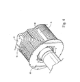
- end windings 50 extend generally axially from the rotor body 40 and form an arc overlying reduced ends of the rotor body for return in an axial direction through the rotor body.
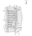
- An end disk 52 is secured to the rotor and to a shield 72 underlying an enclosure 74 ( Figure 5) about the end windings as described below.
- an end winding support assembly 54 is illustrated.
- the assembly 54 includes a plurality of axially extending, circumferentially spaced beams 56 and a corresponding number of axially extending, circumferentially spaced support rakes 58 ( Figures 3 and 5) for spacing the end windings in an axial direction one from the other.
- the beams 56 are secured to the end face of the rotor body, for example, by a dovetail connection, with each beam having a projecting dovetail 60 (Figure 5) for disposition in a corresponding arcuate dovetail slot 62 ( Figures 3 and 5) in the end face of the rotor.
- the beams 56 are circumferentially spaced one from the other and are secured at their opposite ends by bolts 64 ( Figure 5) passing through a radially inner portion of the annular disk 52.
- Each of the axial support rakes 58 includes a base 66 having a pair of depending flanges 68 ( Figure 3) defining a groove for receiving the beams 56 with the flanges 68 straddling the beams. Consequently, the rakes 58 extend axially between the end face of the rotor body and the inside face of the disk 52.
- the rakes 58 include a plurality of spacers or tines 70 for receiving the arcuate portions of the end windings 50 as those end windings extend arcuately over the end of the rotor body. As illustrated in Figure 5, the end windings and rakes are axially confined by a cylindrical end shield 72, in turn radially underlying a cylindrical enclosure 74.
- the radial outer end of the disk 52 is bolted to the end face of the shield 72.
- the beams 56 may have axially extending through holes whereby bolts 73, extending through the disk 52 and the length of the beams 56, may be threaded into female threaded openings 75 in the end face of the rotor in lieu of the dovetail connection.
- a beam which supports an interpolar brace 76 which supports an interpolar brace 76. The brace spaces the outermost coil from one pole against circumferential displacement of the outermost coil of an adjacent coil.
- the disk 52 is weighted.
- the weighting of the disk distributes the mass of the disk to alleviate uneven distribution of the load that serves as the primary cause of distortion, e.g., elliptical or non-concentric deformation, upon rotation of the rotor.
- grooves 80 are formed along the inside face of the disk 52.
- the grooves are diametrically symmetrical such that the weighted portions of the disk, i.e., portions other than the grooves, are diametrically balanced.
- the weight of the disk at locations 90° from the locations of the radial grooves is greater than the weight of the disk at the locations of the grooves.
- the circumferential locations of the heavier portions of the disk preferably lie along the quadrature axis Q to effectively counter the deformation of the end windings toward an elliptical or non-concentric shape.
- the radial passages formed to dynamically balance the rotor at symmetrical diametrical positions also serve as passages for flowing a cooling medium generally radially outwardly of the rotor body. Consequently, apertures 82 are formed through the overlying shield 72 and enclosure 74 and lie in communication with the radial passages 80 which, in turn, lie in communication with a cooling flow manifold, not shown, within the rotor.
- the centrifugal pumping action of the rotating rotor body causes the cooling medium to flow outwardly along the passages 80, cooling the largest of the end windings for exit into the air gap between the rotor body and the stator. Consequently, the radial passages serve the dual purpose of affording transmission of the cooling medium, as well as providing the weight distribution on the end disk which avoids tendencies of the end windings toward an elliptical or non-concentric shape.
- the support assembly including the beams and weights, as well as the end disk, provide axial support for the end windings against thermal expansion of the rotor windings.
- the tines 70 of the rakes 58 also provide a means for supporting the windings 50 during winding assembly and maintain the individual windings separated from one another at a fixed spacing.
Landscapes
- Engineering & Computer Science (AREA)
- Power Engineering (AREA)
- Insulation, Fastening Of Motor, Generator Windings (AREA)
- Iron Core Of Rotating Electric Machines (AREA)
Applications Claiming Priority (2)
| Application Number | Priority Date | Filing Date | Title |
|---|---|---|---|
| US10/849,803 US6972507B1 (en) | 2004-05-21 | 2004-05-21 | End winding restraint in an electrical machine |
| US849803 | 2004-05-21 |
Publications (2)
| Publication Number | Publication Date |
|---|---|
| EP1598921A2 true EP1598921A2 (fr) | 2005-11-23 |
| EP1598921A3 EP1598921A3 (fr) | 2014-04-23 |
Family
ID=34941248
Family Applications (1)
| Application Number | Title | Priority Date | Filing Date |
|---|---|---|---|
| EP05252900.5A Withdrawn EP1598921A3 (fr) | 2004-05-21 | 2005-05-11 | Retenue de conducteurs de tête d'enroulement d'une machine électrique |
Country Status (4)
| Country | Link |
|---|---|
| US (1) | US6972507B1 (fr) |
| EP (1) | EP1598921A3 (fr) |
| JP (1) | JP4776980B2 (fr) |
| CN (1) | CN1700563B (fr) |
Cited By (1)
| Publication number | Priority date | Publication date | Assignee | Title |
|---|---|---|---|---|
| WO2011011801A3 (fr) * | 2009-07-29 | 2012-03-01 | Andritz Hydro Gmbh | Support de tête de bobine d'une machine électrique |
Families Citing this family (5)
| Publication number | Priority date | Publication date | Assignee | Title |
|---|---|---|---|---|
| BRPI1014282A2 (pt) * | 2009-04-24 | 2016-04-05 | Alstom Hydro France | máquina elétrica com cabeça de enrolamento de rotor |
| JP2010259266A (ja) * | 2009-04-27 | 2010-11-11 | Denso Corp | 回転電機の固定子及び回転電機 |
| US8084902B2 (en) * | 2009-05-06 | 2011-12-27 | Hamilton Sundstrand Corporation | End plates for high speed generator applications |
| PT2557664T (pt) * | 2011-08-11 | 2019-07-15 | Ge Renewable Tech | Máquina elétrica rotativa |
| CN114333520B (zh) * | 2022-01-14 | 2023-08-15 | 湖南铁道职业技术学院 | 教学用交流电机组装方法 |
Citations (2)
| Publication number | Priority date | Publication date | Assignee | Title |
|---|---|---|---|---|
| US2844746A (en) * | 1956-02-17 | 1958-07-22 | Gen Electric | Support means for rotor end windings of dynamoelectric machines |
| US6346754B1 (en) * | 1999-06-02 | 2002-02-12 | Hitachi, Ltd. | Electric rotating machine |
Family Cites Families (33)
| Publication number | Priority date | Publication date | Assignee | Title |
|---|---|---|---|---|
| US4363982A (en) | 1981-01-26 | 1982-12-14 | General Electric Company | Dual curved inlet gap pickup wedge |
| US4543503A (en) | 1983-12-20 | 1985-09-24 | General Electric Company | Ventilated end turns for rotor windings of a dynamoelectric machine |
| JPS6271444A (ja) * | 1985-09-25 | 1987-04-02 | Hitachi Ltd | 界磁巻線の極間接続線 |
| US4667125A (en) | 1985-10-25 | 1987-05-19 | General Electric Company | Rotor slot insulation system for electrical machine and article incorporating same |
| US4709177A (en) | 1986-06-30 | 1987-11-24 | General Electric Company | Ventilated end turns for rotor windings of a dynamoelectric machine |
| US4814655A (en) | 1987-12-21 | 1989-03-21 | General Electric Company | Ventilated gusset for single-layer turns in a dynamoelectric machine |
| US5065064A (en) | 1990-05-31 | 1991-11-12 | General Electric Company | Rotor slot insulation in rotors with subslots |
| US5358432A (en) | 1991-04-03 | 1994-10-25 | General Electric Company | Resilient connectors for a generator/motor rotor |
| US5264750A (en) * | 1992-06-17 | 1993-11-23 | General Electric Company | Strain energy control plane for generator rotor field |
| US5281877A (en) | 1992-11-13 | 1994-01-25 | General Electric Company | Dynamoelectric machine rotor endwindings with corner cooling passages |
| GB9505072D0 (en) * | 1995-03-14 | 1995-05-03 | Lucas Ind Plc | A winding end support for a rotary electrical component |
| US5886434A (en) | 1997-03-20 | 1999-03-23 | General Electric Co. | Generator field turn copper |
| US5929550A (en) | 1997-03-20 | 1999-07-27 | General Electric Co. | Ventilated creepage blocks |
| US5986380A (en) | 1998-08-26 | 1999-11-16 | General Electric Co. | Mechanical constraints for tapered end turns of a generator rotor |
| US6198371B1 (en) | 1999-11-09 | 2001-03-06 | General Electric Company | Open magnet with floor mount |
| US6181228B1 (en) | 1999-11-09 | 2001-01-30 | General Electric Company | Superconductive magnet including a cryocooler coldhead |
| US6201462B1 (en) | 1999-11-09 | 2001-03-13 | General Electric Company | Open superconductive magnet having a cryocooler coldhead |
| US6081178A (en) | 1999-11-15 | 2000-06-27 | General Electric Company | Superconductive magnet having a tube suspension assembly |
| US6437476B1 (en) | 1999-12-06 | 2002-08-20 | General Electric Company | Multi-pole electric machine including flat winding for generator fields |
| US6239527B1 (en) | 2000-01-26 | 2001-05-29 | General Electric Company | Non-circular field winding enclosure |
| US6291919B1 (en) | 2000-01-26 | 2001-09-18 | General Electric Company | Conductive structural interface for a non-metallic rotor enclosure |
| US6313561B1 (en) | 2000-01-26 | 2001-11-06 | General Electric Company | Dynamic blocking restraint of a rotor field winding contained by a non-metallic structural rotor enclosure |
| US6495942B1 (en) | 2000-01-26 | 2002-12-17 | General Electric Company | Non-metallic structural rotor enclosure |
| US6339268B1 (en) | 2000-02-02 | 2002-01-15 | General Electric Company | Cooling ventilation circuit for rotor end winding and slot end region cooling |
| US6346753B1 (en) | 2000-04-18 | 2002-02-12 | General Electric Company | Fan and rotor dynamic gas sealing system |
| US6369482B1 (en) | 2000-09-27 | 2002-04-09 | General Electric Company | Generator armature bar support system and related method |
| US6448686B1 (en) | 2000-12-08 | 2002-09-10 | General Electric Company | Packaged stator core and method forming the same |
| US6415613B1 (en) | 2001-03-16 | 2002-07-09 | General Electric Company | Cryogenic cooling system with cooldown and normal modes of operation |
| US6570292B2 (en) * | 2001-05-15 | 2003-05-27 | General Electric Company | High temperature super-conducting rotor coil support with split coil housing and assembly method |
| US6438969B1 (en) | 2001-07-12 | 2002-08-27 | General Electric Company | Cryogenic cooling refrigeration system for rotor having a high temperature super-conducting field winding and method |
| US6442949B1 (en) | 2001-07-12 | 2002-09-03 | General Electric Company | Cryongenic cooling refrigeration system and method having open-loop short term cooling for a superconducting machine |
| JP3735545B2 (ja) * | 2001-07-27 | 2006-01-18 | 三菱電機株式会社 | 回転電機 |
| US6593676B2 (en) * | 2001-09-21 | 2003-07-15 | Siemens Westinghouse Power Corporation | Generator rotor having axial zone blocks and associated methods |
-
2004
- 2004-05-21 US US10/849,803 patent/US6972507B1/en not_active Expired - Fee Related
-
2005
- 2005-05-11 EP EP05252900.5A patent/EP1598921A3/fr not_active Withdrawn
- 2005-05-20 JP JP2005147518A patent/JP4776980B2/ja not_active Expired - Fee Related
- 2005-05-20 CN CN2005100737377A patent/CN1700563B/zh not_active Expired - Fee Related
Patent Citations (2)
| Publication number | Priority date | Publication date | Assignee | Title |
|---|---|---|---|---|
| US2844746A (en) * | 1956-02-17 | 1958-07-22 | Gen Electric | Support means for rotor end windings of dynamoelectric machines |
| US6346754B1 (en) * | 1999-06-02 | 2002-02-12 | Hitachi, Ltd. | Electric rotating machine |
Cited By (3)
| Publication number | Priority date | Publication date | Assignee | Title |
|---|---|---|---|---|
| WO2011011801A3 (fr) * | 2009-07-29 | 2012-03-01 | Andritz Hydro Gmbh | Support de tête de bobine d'une machine électrique |
| RU2537976C2 (ru) * | 2009-07-29 | 2015-01-10 | Андриц Гидро Гмбх | Опорный кронштейн лобовых частей обмотки электрической машины |
| US9225218B2 (en) | 2009-07-29 | 2015-12-29 | Andritz Hydro Gmbh | Winding overhang support of an electrical machine |
Also Published As
| Publication number | Publication date |
|---|---|
| US20050258708A1 (en) | 2005-11-24 |
| EP1598921A3 (fr) | 2014-04-23 |
| CN1700563B (zh) | 2010-09-29 |
| US6972507B1 (en) | 2005-12-06 |
| JP2005341792A (ja) | 2005-12-08 |
| JP4776980B2 (ja) | 2011-09-21 |
| CN1700563A (zh) | 2005-11-23 |
Similar Documents
| Publication | Publication Date | Title |
|---|---|---|
| EP0013157B1 (fr) | Rotors à aimant permanent, notamment pour machines dynamo-électriques | |
| US6979929B2 (en) | System and method for retaining wedges in a rotor | |
| EP1598921A2 (fr) | Retenue de conducteurs de tête d'enroulement d'une machine électrique | |
| US5378953A (en) | Rotor for synchronous motor | |
| US4469970A (en) | Rotor for permanent magnet excited synchronous motor | |
| EP0726638B1 (fr) | Machine tournante électromagnétique comprenant un palier électromagnétique | |
| US6268673B1 (en) | Control coil arrangement for a rotating machine rotor | |
| EP1171938B1 (fr) | Mecanismes de ventilation de bobinage d'extremite directement refroidi par du gaz destines a des machines equipees de rotors a bobine concentrique | |
| JP6507273B2 (ja) | 永久磁石埋込型電動機のためのロータ及びそれを用いた電動機 | |
| EP1976095B1 (fr) | Machine électrique rotative et son rotor | |
| JP2003523157A (ja) | 同心コイルロータを備えた機械のための直接ガス冷却式縦流/横流コイル端通気方式 | |
| US2944171A (en) | Intermediate ring squirrel cage rotor | |
| EP0763880B1 (fr) | Machine électrique à flux magnétique transversal | |
| US4293787A (en) | Stator winding holding structure for rotary electric machine | |
| RU2654211C2 (ru) | Ротор электрической машины | |
| US4327303A (en) | Rotor assembly for a dynamoelectric machine | |
| PL182491B1 (pl) | Wirnik maszyny elektrycznej z biegunami pazurowymi | |
| CA2023234C (fr) | Machine tournante electrique; methode de fabrication de ladite machine | |
| US20040055142A1 (en) | Method and apparatus for reducing dynamo-electric machine vibration | |
| US6759770B1 (en) | Cooling system for modular field windings of a generator | |
| JP3522943B2 (ja) | 回転電機の回転子 | |
| US4370580A (en) | Reluctance motor | |
| JP7031619B2 (ja) | 回転電機 | |
| JP6856011B2 (ja) | 回転電機のロータ | |
| KR102681776B1 (ko) | 자속불균일을 보상하는 백아이언을 구비하는 로터 및 이를 포함하는 축방향 자속 모터 |
Legal Events
| Date | Code | Title | Description |
|---|---|---|---|
| PUAI | Public reference made under article 153(3) epc to a published international application that has entered the european phase |
Free format text: ORIGINAL CODE: 0009012 |
|
| AK | Designated contracting states |
Kind code of ref document: A2 Designated state(s): AT BE BG CH CY CZ DE DK EE ES FI FR GB GR HU IE IS IT LI LT LU MC NL PL PT RO SE SI SK TR |
|
| AX | Request for extension of the european patent |
Extension state: AL BA HR LV MK YU |
|
| RIC1 | Information provided on ipc code assigned before grant |
Ipc: H02K 3/46 20060101ALI20130204BHEP Ipc: H02K 3/50 20060101AFI20130204BHEP |
|
| PUAL | Search report despatched |
Free format text: ORIGINAL CODE: 0009013 |
|
| AK | Designated contracting states |
Kind code of ref document: A3 Designated state(s): AT BE BG CH CY CZ DE DK EE ES FI FR GB GR HU IE IS IT LI LT LU MC NL PL PT RO SE SI SK TR |
|
| AX | Request for extension of the european patent |
Extension state: AL BA HR LV MK YU |
|
| RIC1 | Information provided on ipc code assigned before grant |
Ipc: H02K 3/50 20060101AFI20140319BHEP Ipc: H02K 3/46 20060101ALI20140319BHEP |
|
| AKY | No designation fees paid | ||
| AXX | Extension fees paid |
Extension state: AL Extension state: YU Extension state: HR Extension state: BA Extension state: MK Extension state: LV |
|
| REG | Reference to a national code |
Ref country code: DE Ref legal event code: R108 |
|
| REG | Reference to a national code |
Ref country code: DE Ref legal event code: R108 Effective date: 20150106 |
|
| STAA | Information on the status of an ep patent application or granted ep patent |
Free format text: STATUS: THE APPLICATION IS DEEMED TO BE WITHDRAWN |
|
| 18D | Application deemed to be withdrawn |
Effective date: 20141024 |