Technical Field
The present invention relates to an acceleration sensor detecting inclined
displacement of a predetermined article from its basic position.
Background Art
Recently, acceleration sensors having a movable structural portion and utilizing
gravity acceleration to detect inclined displacement of an apparatus or the like have been
developed. Such an acceleration sensor generally utilizes piezoresistance effect of a
semiconductor. For example, a cavity portion is formed within a silicon substrate to
accommodate therein a block-shaped movable structural portion freely movable in three-dimensional
directions. The movable structural portion is coupled to the silicon
substrate with a beam which is a bridge structure, and is arranged such that stress
corresponding to the movement of the movable structural portion is applied to a piezo
element. Then, a change in the stress applied to the piezo element is detected as a
change in resistance. Instead of the piezo element, a capacitive element provided in the
movable structural portion can be used as an element for detecting the displacement.
Disclosure of the Invention
In the acceleration sensor as described above, further improvement in detection
accuracy is required.
Accordingly, an object of the present invention is to provide an acceleration
sensor capable of detecting an inclination angle of an apparatus with high accuracy.
To achieve the foregoing object, an acceleration sensor in accordance with a first
mode of the present invention is an acceleration sensor detecting inclined displacement
of a predetermined article from a basic position, including a sensor chip having a
detection plane including one detection axis or two crossing detection axes detecting the
inclined displacement. An axis orthogonal to the detection plane of the sensor chip is
disposed in parallel with a standard plane of the article in the basic position. Then, the
sensor chip obtains an output signal according to the inclined displacement of the
standard plane.
A method in accordance with a second mode of the present invention is a
method of detecting inclined displacement of a predetermined article with respect to a
basic position using a sensor chip having a detection plane including one detection axis
or two crossing detection axes. The sensor chip is disposed such that an axis
orthogonal to the detection plane is in parallel with a standard plane corresponding to
the basic position of the article, and at the same time the detection axis is inclined at a
predetermined angle with respect to the standard plane. Then, the inclined
displacement of the article is detected based on displacement in the sensor chip in a
direction of the detection axis.
Preferably, in each mode described above, the detection axis is inclined at a
predetermined angle (45° or the like) with respect to the standard plane.
A mounting board in accordance with a third mode of the present invention is a
rectangular mounting board on which a sensor chip for an acceleration sensor is
mounted, and the sensor chip is mounted such that a detection axis of the sensor is
inclined from vertical and from horizontal with respect to each edge of the board. Here,
a sensor chip of a semiconductor piezoresistance type formed of a silicon substrate with
a (110) plane is preferably employed.
Brief Description of the Drawings
Figs. 1A and 1B are explanatory views (cross-sectional views) illustrating a
principle of an acceleration sensor applicable in the present invention.
Fig. 2 is a plan view illustrating a structure of an acceleration sensor in
accordance with a first embodiment of the present invention.
Fig. 3 is a cross-sectional view taken along a direction III-III in Fig. 2,
illustrating an internal structure of the acceleration sensor in accordance with the first
embodiment.
Fig. 4 is a schematic perspective view illustrating a mounting board having the
acceleration sensor in accordance with the first embodiment.
Fig. 5 is an explanatory view (a perspective view) illustrating a state in which the
mounting board shown in Fig. 4 is installed in an apparatus.
Fig. 6 is an explanatory view illustrating an actual state (orientation,
arrangement) of using the acceleration sensor in accordance with the first embodiment,
showing a positional relation with a standard plane of the apparatus in which the
acceleration sensor is installed.
Fig. 7 is a graph illustrating outputs of the acceleration sensor in accordance
with the first embodiment relative to an inclination angle of the apparatus (the standard
plane).
Fig. 8 is a graph illustrating changes in the outputs of the acceleration sensor in
accordance with the first embodiment relative to the inclination angle of the apparatus
(the standard plane).
Fig. 9 is an explanatory view illustrating an actual state (orientation,
arrangement) of using an acceleration sensor in accordance with a second embodiment
of the present invention, showing a positional relation with a standard plane of an
apparatus in which the acceleration sensor is installed.
Fig. 10 is a graph illustrating outputs of the acceleration sensor in accordance
with the second embodiment relative to an inclination angle of the apparatus (the
standard plane).
Fig. 11 is a graph illustrating changes in the outputs of the acceleration sensor in
accordance with the second embodiment relative to the inclination angle of the
apparatus (the standard plane).
Fig. 12 is a schematic perspective view illustrating a mounting board having the
acceleration sensor in accordance with the second embodiment.
Fig. 13 is an explanatory view (a perspective view) illustrating a state in which
the mounting board shown in Fig. 12 is installed in the apparatus.
Fig. 14 is an explanatory view illustrating an actual state (orientation,
arrangement) of using an acceleration sensor in accordance with a third embodiment of
the present invention, showing a positional relation with a standard plane of an
apparatus in which the acceleration sensor is installed.
Best Modes for Carrying Out the Invention
Firstly, a principle serving as a basis for the present invention will briefly be
described. Figs. 1A and 1B show a schematic structure of an acceleration sensor
serving as a basis for the present invention. A cavity portion is formed within a silicon
substrate 1 to accommodate therein a block-shaped movable structural portion 2 freely
movable in three-dimensional directions. Movable structural portion 2 is coupled to
silicon substrate 1 with a beam 4 which is a bridge structure, and is arranged such that
stress corresponding to the movement of movable structural portion 2 is applied to a
piezo element 4 provided on beam 4. Then, a change in the stress applied to piezo
element 4 is detected as a change in resistance.
The acceleration sensor shown in Figs. 1A and 1B is provided such that a chip
surface (a detection plane) is horizontal a standard plane 3 of an apparatus in a basic
position. In other words, an axis Y horizontal to the detection plane is provided as a
rotation axis of standard plane 3, and outputs a vector component for each axis of
weight acceleration caused by inclination of standard plane 3 (3a). Figs. 1A and 1B
show a three-axis acceleration sensor which is capable of detecting acceleration on X, Y
and Z axes with a single chip, and it is structured such that the X and Y axes are
disposed in a horizontal plane of the chip (the detection plane) and the Z axis is disposed
vertically with respect to the chip. Assume that an inclination angle with respect to
the horizontal is given to standard plane 3 of the apparatus as a result of rotation about
the Y axis, the corresponding output of inclination angle provides Ax=A•sin as an
output on the X axis and Az=A•cos as an output on the Z axis, as the vector
components of gravity acceleration.
Since these outputs are those of trigonometric functions, in terms of inclination
accuracy (resolution), it is desirable to use the output on the X axis, which is a sine
function, at an angle close to 0° and use the output on the Z axis, which is a cosine
function, at an angle close to ±90° in order to obtain maximum output change relative to
the inclination angle. However, even if the axes are selected to obtain maximum
output in this manner, the maximum output obtained is limited to a value determined by
the sensitivity of the sensor, which has been insufficient for an application where a highly
accurate output of the inclination angle is required. Further, detection at an angle close
to 0° or ±90° described above is not necessarily desired in some applications, and there
is an application where detection of any inclination angle, for example an angle close to
±45°, with high accuracy is desired.
Hereinafter, embodiments of the present invention will be described, taking an
acceleration sensor detecting inclination displacement of an apparatus as an example.
Fig. 2 is a plan view illustrating a structure of an acceleration sensor 10 in
accordance with a first embodiment of the present invention. Fig. 3 is a cross-sectional
view illustrating an internal structure of acceleration sensor 10. Acceleration sensor 10
in accordance with the present embodiment includes a silicon substrate 12 and a
movable structural portion (a movable mass) 14 accommodated in silicon substrate 12
near its center to be movable in any direction from side to side or top to bottom. A
box-shaped space is formed in the center of silicon substrate 12, in which movable
structural portion 14 is formed. Movable structural portion 14 is shaped like a so-called
clover, with four squares coupled in the center, to improve inertial force.
Basically, the upper surface of movable structural portion 14 is designed to be flush with
the upper surface of silicon substrate 12.
Sensor 10 is further provided with four beams (supporting bars) 16 connecting
movable structural portion 14 and silicon substrate 12, and a piezoresistance element 18
disposed at a root of each beam 16. For the detection of an output on one axis, four
piezoresistance elements 18 form a Wheatstone's bridge to output a voltage signal.
Each beam 16 is disposed in movable structural portion 14 at a position corresponding
to between leaves of the clover. An electrode pad 20 is formed on the upper surface of
silicon substrate 12, and electrically connected with piezoresistance element 18 via an
interconnection not shown. As shown in Fig. 3, silicon substrate 12 is fixed onto a die
bond surface 24.
In manufacturing acceleration sensor 10 in accordance with the present
embodiment, firstly an SOI substrate having an active layer (Si), a buried oxide film
layer (SiO2), and an Si substrate is formed. Thereafter, piezoresistance element 18, a
metal interconnection, and electrode pad 20 are formed into an array to configure a
bridge circuit on the active layer of the SOI substrate using a semiconductor processing
technique, forming a sensor circuit. Next, beam portion 16 is formed by Si Deep RIE
(Reactive Ion Etching).
Thereafter, Si Deep RIE is also conducted from the side of the Si substrate to
form movable structural portion 14, and the buried oxide film is etched to release
movable structural portion 14. Next, dicing is performed to cut the SOI substrate into
sensor chips, forming individual sensor chips.
Acceleration sensor 10 manufactured as described above is mounted for example
on a rectangular mounting board 100 as shown in Fig. 4. As shown in Fig. 5, mounting
board 100 is used to stand vertical to an apparatus 200 such as a projector, a head
mounted display, a portable game apparatus, or a game controller. Sensor chip 10 is
mounted on mounting board 100 such that each of two orthogonal detection axes is
horizontal to each edge of mounting board 100.
Fig. 6 schematically illustrates an arrangement (orientation) when acceleration
sensor 10 is installed in the apparatus. In the drawing, SP indicates a standard plane
when the apparatus equipped with sensor 10 is in a basic position. For example, in a
projector, standard plane SP coincides with a horizontal plane of the projector when it is
in a desirable status of use (basic position). When the apparatus is in the basic position,
a detection plane (14) of sensor 10 stands vertical. Specifically, a detection axis Z
orthogonal to detection axes X and Y in the detection plane (14) is disposed in parallel
with standard plane SP of the apparatus in the basic position.
In the present invention, a "detection axis" refers to a direction in which
displacement is detected, and it does not necessarily mean a physical axis. Specifically,
when a piezoresistance element is used as in the present embodiment, the direction of
the beam in which the element is disposed may coincide with the detection axis.
However, when a capacitive element is disposed in the movable structural portion and
displacement of the movable structural portion is measured by the capacitive element,
the direction of the beam may not coincide with the detection axis.
In the present embodiment, inclined displacement of standard surface SP is
determined based on a difference between or a sum of an output signal on the detection
axis X and an output signal on the detection axis Y, and the inclined displacement is
corrected if necessary.
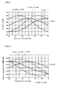
Fig. 7 shows an output on the X axis, an output on the Y axis, the output on the
Y axis - the output on the X axis, and the output on the Y axis + the output on the X
axis with respect to inclination angle on this occasion, and Fig. 8 shows changes in the
outputs per 1° (an output equivalent to gravity acceleration is indicated as A). As can
be seen from Fig. 8, an absolute value of the change in the output on the Y axis - the
output on the X axis at an angle close to +45° and an absolute value of the change in the
output on the Y axis + the output on the X axis at an angle close to -45° are greater
than absolute values of the changes in the outputs on the X axis and the Y axis.
Specifically, while the absolute value of the change in the output on the X axis or the Y
axis is 12.23 × 10⁻³A/°, the absolute value of the change in the output on the Y axis - the
output on the X axis or the output on the Y axis + the output on the X axis is 24.68×10⁻³A/°,
which is about twice greater than the former value.
As described above, an inclination angle for example close to ±45° can be
detected with high accuracy by obtaining the sum of or the difference between the
outputs on the X axis and the Y axis. In particular, since the technique to obtain the
difference between the outputs on the two axes, such as the output on the Y axis - the
output on the X axis, can be expected to cancel a noise component or a thermal
characteristic component of the output on each axis, inclination accuracy is improved
and a desirable effect can be obtained.
Fig. 9 schematically illustrates an arrangement (orientation) when an acceleration
sensor 110 in accordance with a second embodiment of the present invention is installed
in an apparatus. The basic structure of sensor 110 in the present embodiment is the
same as that of sensor 10 in the first embodiment described above, except for a relative
positional relation with the mounting board and the apparatus to be installed. In the
drawing, SP indicates a standard plane when the apparatus equipped with sensor 110 is
in a basic position, and numerals 112, 114, and 116 correspond to silicon substrate 12,
movable structural portion 14, and beam 16 in the first embodiment, respectively.
When the apparatus is in the basic position, a detection plane (114) of sensor 110 stands
vertical. Specifically, the detection axis Z orthogonal to the detection axes X and Y in
the detection plane (114) is disposed in parallel with standard plane SP of the apparatus
in the basic position. Then, inclined displacement of standard surface SP is determined
based on a difference between or a sum of an output signal on the detection axis and an
output signal on the detection axis Y, and the inclined displacement is corrected if
necessary.
In the present embodiment, the detection axes X and Y orthogonal to each other
are each disposed to form an angle of 45° with respect to standard plane SP. It is to be
noted that the angle between the detection axis X or Y and standard plane SP is not
limited to 45°, and can be changed as appropriate.
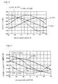
Fig. 10 shows an output on the X axis, an output on the Y axis, the output on
the Y axis - the output on the X axis, and the output on the Y axis + the output on the X
axis with respect to inclination angle . Fig. 11 shows changes in the outputs per 1°
when an output equivalent to gravity acceleration is indicated as A. As can be seen
from Fig. 10, the change in the output on the X axis or the Y axis at an angle close to
±45° is increased by disposing the sensor to be inclined at 45°. As a result, accuracy in
detecting inclination can be improved. While the absolute value of the output on the X
axis or the Y axis is 12.23 × 10⁻³ A/° in the first embodiment, an absolute value of the
output on the X axis or the Y axis is 17.60×10⁻³A/° in the present embodiment, which is
about 1.44 times greater than the former value.
Further, as can be seen from Fig. 11, as for the change in the output at an angle
close to 0°, the output on the Y axis - the output on the X axis has the greatest value,
which is 24.68×10⁻³A/° in an absolute value, about twice greater than an absolute value
of 12.45 × 10⁻³A/° of the X axis or the Y axis. Furthermore, as for the change in the
output at an angle close to ±90°, the output on the Y axis + the output on the X axis has
the greatest value, which is 24.68 × 10⁻³A/° in an absolute value, about twice greater than
an absolute value of 12.23×10⁻³A/° of the X axis or the Y axis.
As described above, an inclination angle for example close to 0°, ±90° can be
detected with high accuracy by obtaining the sum of or the difference between the
outputs on the X axis and the Y axis. In particular, since the technique to obtain the
difference between the outputs on the two axes, such as the output on the Y axis - the
output on the X axis, can be expected to cancel a noise component or a thermal
characteristic component of the output on each axis, inclination accuracy is improved
and a desirable effect can be obtained.
Acceleration sensor 110 in accordance with the present embodiment is mounted
on mounting board 100 as shown in Fig. 12. Then, as shown in Fig. 13, mounting
board 100 is used to stand vertical to apparatus 200 such as a projector, a head mounted
display, a portable game apparatus, or a game controller. Sensor chip 110 is mounted
on mounting board 100 such that two orthogonal detection axes are inclined at 45° from
the vertical and from the horizontal with respect to each edge of mounting board 100.
Fig. 14 is a schematic view illustrating a direction (an orientation) in which an
acceleration sensor 210 in accordance with a third embodiment of the present invention
is installed in an apparatus. In the drawing, SP indicates a standard plane when the
apparatus equipped with sensor 210 is in a basic position, and numerals 212, 214, and
216 correspond to silicon substrate 12, movable structural portion 14, and beam 16 in
the first embodiment, respectively. When the apparatus is in the basic position, a
detection plane (214) of sensor 210 stands vertical. Specifically, the detection axis Z
orthogonal to the detection axes X and Y in the detection plane (214) is disposed in
parallel with standard plane SP of the apparatus in the basic position. Then, inclined
displacement of standard surface SP is determined based on a difference between or a
sum of an output signal on the detection axis X and an output signal on the detection
axis Y, and the inclined displacement is corrected if necessary.
Mounting the acceleration sensor to form an angle of 45° with respect to
standard plane SP of the apparatus may cause a problem such as occupying a large area
on a printed board or a problem in terms of accuracy in a mounting angle. Such a
problem can be solved by using a semiconductor piezoresistance acceleration sensor
made of a silicon substrate with a (110) plane as shown in Fig. 14. In semiconductor
piezoresistance, when the piezoresistance is formed in the direction of 45° with respect
to a <001> axis or a <110> axis in the (110) plane in crystal plane orientation, a
piezoresistance coefficient is increased compared to the case where the piezoresistance
is formed on a <110> axis in a typical (100) plane in crystal plane orientation, allowing
for highly sensitive detection. As shown in Fig. 14, since the piezoresistance formed of
the (110) plane has a detection axis exactly in the direction of 45° with respect to an
edge of the chip, there is no need to incline the chip itself at the time of mounting.
Although the embodiments (modes of operation) of the present invention have
been described, the present invention is not limited to these embodiments, and can be
modified within a category of technical idea described in the scope of the claims.