EP1598608A2 - Dispositif de refroidissement pour fenêtre bombée exposée à un rayonnement, récepteur solaire et procédé de refroidissement d'une fenêtre bombée - Google Patents
Dispositif de refroidissement pour fenêtre bombée exposée à un rayonnement, récepteur solaire et procédé de refroidissement d'une fenêtre bombée Download PDFInfo
- Publication number
- EP1598608A2 EP1598608A2 EP05010090A EP05010090A EP1598608A2 EP 1598608 A2 EP1598608 A2 EP 1598608A2 EP 05010090 A EP05010090 A EP 05010090A EP 05010090 A EP05010090 A EP 05010090A EP 1598608 A2 EP1598608 A2 EP 1598608A2
- Authority
- EP
- European Patent Office
- Prior art keywords
- nozzles
- window
- cooling device
- cooling
- cooling fluid
- Prior art date
- Legal status (The legal status is an assumption and is not a legal conclusion. Google has not performed a legal analysis and makes no representation as to the accuracy of the status listed.)
- Withdrawn
Links
Images

Classifications
-
- F—MECHANICAL ENGINEERING; LIGHTING; HEATING; WEAPONS; BLASTING
- F24—HEATING; RANGES; VENTILATING
- F24S—SOLAR HEAT COLLECTORS; SOLAR HEAT SYSTEMS
- F24S20/00—Solar heat collectors specially adapted for particular uses or environments
- F24S20/20—Solar heat collectors for receiving concentrated solar energy, e.g. receivers for solar power plants
-
- F—MECHANICAL ENGINEERING; LIGHTING; HEATING; WEAPONS; BLASTING
- F24—HEATING; RANGES; VENTILATING
- F24S—SOLAR HEAT COLLECTORS; SOLAR HEAT SYSTEMS
- F24S40/00—Safety or protection arrangements of solar heat collectors; Preventing malfunction of solar heat collectors
- F24S40/50—Preventing overheating or overpressure
- F24S40/55—Arrangements for cooling, e.g. by using external heat dissipating means or internal cooling circuits
-
- Y—GENERAL TAGGING OF NEW TECHNOLOGICAL DEVELOPMENTS; GENERAL TAGGING OF CROSS-SECTIONAL TECHNOLOGIES SPANNING OVER SEVERAL SECTIONS OF THE IPC; TECHNICAL SUBJECTS COVERED BY FORMER USPC CROSS-REFERENCE ART COLLECTIONS [XRACs] AND DIGESTS
- Y02—TECHNOLOGIES OR APPLICATIONS FOR MITIGATION OR ADAPTATION AGAINST CLIMATE CHANGE
- Y02E—REDUCTION OF GREENHOUSE GAS [GHG] EMISSIONS, RELATED TO ENERGY GENERATION, TRANSMISSION OR DISTRIBUTION
- Y02E10/00—Energy generation through renewable energy sources
- Y02E10/40—Solar thermal energy, e.g. solar towers
Definitions
- the invention relates to a cooling device for a radiation-loaded arched window, in particular a radiation receiver.
- the invention further relates to a radiation receiver.
- the invention relates to a method for cooling a curved Window.
- Radiation receivers serve to generate solar thermal heat to a gas pass.
- a closed radiation receiver is to in a pressure vessel arranged an absorber which heated solar thermal becomes. The radiation enters through a curved window in the Pressure vessel. This window is exposed to a high heat load.
- Radiation receiver are, for example, in DE 197 10 186 A1 and the DE 100 20 322 A1.
- the invention is based on the object, an effective cooling device for a radiation-loaded domed window.
- the cooling device includes a plurality of nozzles which are proximate to a window foot are arranged around this distributed and over which the window with Cooling fluid can be acted upon, and a control device for activation thedeungsfluidbeetzschlagung by the nozzles comprises, which are such is formed, that the nozzles with respect to thedeungsfluidbeetzschlagung are alternately activated.
- the nozzles can be a periodically circulating cooling fluid flow generate, which flows in accordance with the window. In particular This ensures that even a vertex area of the window effectively is cooled.
- the inventive solution can be a homogeneous cooling effect achieve, with a high cooling capacity with reduced energy consumption is reached. Furthermore, can be an effective window cleaning cause.
- the nozzles are arranged distributed on a curved line, which coaxial with a window foot peripheral curve. This can be just one Flow window foot evenly over time.
- a domed window in a radiation receiver in Foot area a round cross section.
- the nozzles arranged on a circle.
- the nozzles are evenly spaced. Thereby leaves to achieve a uniform flow with cooling fluid and so in turn a uniform cooling effect with respect to the entire window area to reach.
- the nozzles are arranged so that a concave side of the Window can be acted upon with cooling fluid.
- the nozzles are characterized Arrange outside a pressure vessel. This is also the cooling fluid supply simplified.
- the nozzles are arranged so that an outside of the window (relative to an interior of a pressure vessel) can be acted upon with cooling fluid.
- the nozzles are arranged so that in particular parallel to a window axis cooling fluid tangentially the window or approximately tangential flows. If the deviation from one tangential flow is too high (eg more than 10 degrees), then a footer of the window, as experiments have shown, no longer sufficiently cooled.
- nozzles around the window foot circumference circumferentially alternately activated. This allows a circumferential Create cooling fluid flow with which the window can be flowed.
- temporal Means can thereby apply the window evenly with cooling fluid in turn to achieve effective cooling. Especially a homogeneous surface cooling is achieved.
- the Nozzles are activated so that a periodic circulation of the flow of the Window is done around the window foot. This will give a uniform surface area achieved the window with cooling fluid, so that in particular also a vertex area is coolable. Furthermore, this is the training of Prevents stagnation points with greatly reduced cooling effect.
- the mass flow of the emitted cooling fluid is adjustable. This can be an optimal adaptation to the present Operating conditions are achieved.
- To adjust the mass flow is For example, set a blower power.
- the circulation period is adjustable.
- the cooling performance depends on the amount of heat absorbed. It may be necessary to choose a smaller cycle period for higher absorbed amounts of heat. Due to the adjustability is an optimized adaptation to the currently available Conditions possible.
- the nozzles are activated by the control device so that a Anström Scheme the window with cooling fluid to a Novafußmon moves periodically. On average, this can be a uniform Apply to the window with cooling fluid, the training of stagnation points is prevented.
- the activation of adjacent nozzles occurs periodically, so to generate a circulating cooling fluid flow.
- each nozzle or a group of nozzles with respect the cooling fluid supply is individually controlled.
- each nozzle or a group of nozzles associated with a controllable switch may be a Act solenoid valve.
- the controllable switch may be a Act solenoid valve.
- About the switch can then be set whether a Nozzle is supplied with cooling fluid or not. Depending on the setting will emitted by the nozzle cooling fluid or not.
- Control of the switch can thereby be a periodically rotating Create cooling fluid flow.
- a rotatable cover provided for the nozzles, which at least one recess for activation comprising at least one nozzle.
- the cover Depending on the rotation position of the cover are one or more nozzles fordeungsfluidbeetzschlagung the Window released. The rotation alternates this release, that is the nozzles are activated and deactivated alternately.
- Cover which is designed for example as an annular disc, can be then again generate a periodically circulating cooling fluid flow, the This means that a periodically modulated mass flow can be generated.
- a flow distributor is provided to the nozzles To provide cooling fluid.
- the flow distributor then provides the cooling fluid (For example, air) the nozzles ready.
- individual cooling fluid ducts to the nozzles or to a group of nozzles provided.
- These cooling fluid ducts are in particular pressurized. This allows the nozzles or a group individually controlled by nozzles, so in turn a periodically circulating To generate cooling fluid flow. It is also possible that a nozzle ring, which holds the nozzles, sits on a diffuser.
- the flow distributor comprises a diffuser. This can be one Fan upstream.
- the flow distributor is arranged externally or in a device which is arranged in front of or at the window integrated is.
- the flow distributor in a secondary concentrator or window flange integrated.
- individual supply lines are provided in case of an external Flow distributor. These are not necessary in the case of an integrated flow distributor.
- the cooling device according to the invention can be in a radiation receiver and, in particular, integrate into it.
- the invention is also based on the object, an effective method for To provide cooling of a domed window by means of a cooling fluid.
- thedeungsfluidbeetzschlagung takes place around a window foot circulating periodically. This can be under the prevention of training of stagnation points a on average homogeneousdeungsfluidbeetzschlagung of the window.
- nozzles with respect to thedeungsfluidbeetzschlagung of Window periodically alternately activated so as to save energy a homogeneous cooling of the window while preventing the formation of To get stagnation points.
- An embodiment of a cooling device 10 according to the invention is arranged on a volumetric radiation receiver 12.
- the radiation receiver 12 includes a pressure vessel 14 having an innerliner 16.
- a first flow guide 18 for supplying formed gas to be heated (especially air).
- a second Flow guide 20 for the removal of heated gas (in particular Air).
- an absorber 22 is arranged, in such a way that aufloomendes gas from the first flow guide 18 to the absorber 22nd supplied for heat absorption.
- the first Flow guide 18 is formed so that the absorber 22 surface to be heated Gas can be acted upon.
- an opening 24 is formed, at which a window 26th is arranged.
- the window is curved and in particular dome-shaped with a foot area (window foot) 28 and a vertex area 30.
- the window 26 which is made of quartz glass, for example, can (concentrated) radiation enter the pressure vessel 14 and the Heat up absorber 22 in order to heat a gas such as air.
- the absorber 22 is arranged for this purpose in the pressure vessel 14 around the window 26.
- a secondary concentrator 32 for radiation and arranged in particular solar radiation. Via the secondary concentrator 32 can be concentrated in a primary concentrator solar radiation on the Concentrate opening 24 and thus focus on the absorber 22.
- the Primary concentrator is for example by one or more heliostats educated.
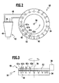
- nozzles 34 ( Figures 2 and 3) through which the window 26 at one of the opening 24 facing outside 36 with cooling fluid and in particular air can be acted upon.
- the nozzles 34 are arranged so that approximately axially exiting cooling fluid as a free jet, the outside 36 of the Window 26 in the foot region 28 at least approximately tangentially flows.
- the axial direction is a direction parallel to the window axis. It forms then a cooling fluid stream 38, which on the outside 36 of the window 26 flows and this cools. In addition, the corresponding ensures Cooling fluid stream 38 also for cleaning the window.
- the nozzles 34 are distributed around a circumference of the foot portion 28 of the window 26 arranged so that the entire foot portion 28 of the window 26 with cooling fluid can be acted upon.
- the nozzles 34 are uniform spaced apart.
- the nozzles 34 are arranged on a curved line 40, wherein the curved line 40 has the same shape as the circumferential line and in particular coaxial with the peripheral line of the foot portion 28 of the window 26.
- the peripheral line of the window 26 will be a circle, so that also the curve line 40 is a circular line (with a smaller radius than the Circumferential line of the window 26).
- nozzles 34 are provided. It can also be a larger number or a smaller number of Nozzle 34 may be provided.
- the nozzles 34 are stationary on the pressure vessel 14 or a window flange arranged, that is, they are firmly positioned with respect to the pressure vessel 14.
- a flow distributor 42 For supplying cooling fluid to the nozzles 34 is a flow distributor 42 provided.
- a diffuser 44 which externally with respect to the pressure vessel 14 is arranged.
- the diffuser 44 has a distributor plate 46, from the respective cooling fluid supply lines or hoses 48 the respective nozzles 34 are guided.
- Eighteen lines 48 are provided with eighteen nozzles.
- the diffuser is upstream of a fan, wherein preferably the blower power adjustable is.
- the flow distributor 42 into a device is integrated, which is arranged in front of the pressure vessel 14.
- a periodic to the circumference of Foot portion 28 of the window 26 circulating free jet flow of the convex Outside 36 of the window 26 takes place.
- a control device 50 is provided to control this flow.
- the nozzles 34 are periodically alternating with respect to the cooling fluid admission of the outside 36 of the window 26 is activated.
- the activation is via the control device 50 controlled.
- the Control device 50 a rotatably driven annular disc 52, which above a nozzle 34 supporting the nozzle ring 54 is arranged. Of the Nozzle ring 54 is firmly seated on the pressure vessel 14. The annular disc 52 is around a Axis 56 rotatable relative to the nozzle ring 54. For driving the rotational movement a drive 58 is provided, which outside the opening 24 in Pressure vessel 14 is seated. For example, the annular disc 52 is on its outside provided with gears in the corresponding gears of the motor 58th can intervene.
- the annular disc 52 comprises at least one recess 60 through which certain nozzles are releasable, that is activated, so that over the shared nozzles cooling fluid flow to the outside 36 of the window 26 can. Outside the recess 60 and the recesses 60th covers the annular disc 52 from the corresponding nozzles 34, so that they are not are activated. In the example shown in Figures 2 and 3 a Momentary position of the annular disc covers the annular disc 52, the nozzles one to five and ten to eighteen off, so that they are not activated, that is about these nozzles nodeffenbeetzschung of the window 26 takes place.
- the annular disc 52 comprises four recesses 62a, 62b, 62c and 62d, for example in the form of bores.
- four nozzles can be activated simultaneously.
- the nozzles six, seven, eight and nine are activated so that the area of the window 26, which is located near the nozzles six, seven, eight and nine, with cooling fluid is charged.
- the annular disc 52 rotates at a certain speed. If, for example starting from the position shown in Figures 2 and 3, the annular disc counterclockwise continues to rotate, then the nozzle is deactivated six and the nozzle is activated ten. At the same time there is always a group of four Nozzles activated. During the further rotation is an adjacent in the direction of rotation Nozzle activated while deactivating an adjacent nozzle in reverse direction becomes.
- the acted upon with cooling fluid portion of the window 26 rotates in a sense along the perimeter of the foot region 28.
- the solution according to the invention can be a high cooling capacity at reduced Achieve energy consumption.
- the cooling effect with respect to the total area of the window 26 is homogenized.
- the individual nozzles 34 with respect to the Cooling fluid supply are individually controlled to activate the nozzles or disable. It can be any nozzle 34 or a group of Nozzles 34 may be associated with a switch via which is switchable, whether a nozzle supplied with cooling fluid or not. By appropriate control the switch can be reached a periodically modulated cooling fluid flow.
- the period of thedeflufluidanströmung the window 26, which, for example is adjusted by the rotation period of the annular disc 52 is in Depending on the amount of heat absorbed and the tolerable temporal temperature fluctuations on the window surface. For example It may be necessary to use a higher radiation power shorter cycle time (higher rotation frequency).
- a typical one Value for the orbital frequency is 0.05 Hz.
- the cooling effect can be increased by giving the nozzles a larger mass flow is supplied.
- this mass flow is adjustable and thus the emitted cooling fluid flow adjustable.
Landscapes
- Engineering & Computer Science (AREA)
- Physics & Mathematics (AREA)
- Life Sciences & Earth Sciences (AREA)
- Sustainable Development (AREA)
- Sustainable Energy (AREA)
- Thermal Sciences (AREA)
- Chemical & Material Sciences (AREA)
- Combustion & Propulsion (AREA)
- Mechanical Engineering (AREA)
- General Engineering & Computer Science (AREA)
- Photovoltaic Devices (AREA)
Applications Claiming Priority (2)
| Application Number | Priority Date | Filing Date | Title |
|---|---|---|---|
| DE102004026517 | 2004-05-19 | ||
| DE102004026517A DE102004026517B3 (de) | 2004-05-19 | 2004-05-19 | Kühlungsvorrichtung für strahlungsbeaufschlagte gewölbte Fenster, Strahlungsempfänger und Verfahren zur Kühlung eines gewölbten Fensters |
Publications (2)
| Publication Number | Publication Date |
|---|---|
| EP1598608A2 true EP1598608A2 (fr) | 2005-11-23 |
| EP1598608A3 EP1598608A3 (fr) | 2010-10-20 |
Family
ID=34936319
Family Applications (1)
| Application Number | Title | Priority Date | Filing Date |
|---|---|---|---|
| EP05010090A Withdrawn EP1598608A3 (fr) | 2004-05-19 | 2005-05-10 | Dispositif de refroidissement pour fenêtre bombée exposée à un rayonnement, récepteur solaire et procédé de refroidissement d'une fenêtre bombée |
Country Status (2)
| Country | Link |
|---|---|
| EP (1) | EP1598608A3 (fr) |
| DE (1) | DE102004026517B3 (fr) |
Cited By (5)
| Publication number | Priority date | Publication date | Assignee | Title |
|---|---|---|---|---|
| US8378280B2 (en) | 2007-06-06 | 2013-02-19 | Areva Solar, Inc. | Integrated solar energy receiver-storage unit |
| US8739512B2 (en) | 2007-06-06 | 2014-06-03 | Areva Solar, Inc. | Combined cycle power plant |
| US8807128B2 (en) | 2007-08-27 | 2014-08-19 | Areva Solar, Inc. | Linear fresnel solar arrays |
| US9022020B2 (en) | 2007-08-27 | 2015-05-05 | Areva Solar, Inc. | Linear Fresnel solar arrays and drives therefor |
| CN115038914A (zh) * | 2019-12-26 | 2022-09-09 | 信赫利恩有限公司 | 接收器 |
Families Citing this family (13)
| Publication number | Priority date | Publication date | Assignee | Title |
|---|---|---|---|---|
| US20110232635A1 (en) * | 2010-03-29 | 2011-09-29 | Intevep, S.A. | Concentrated solar radiation assembly |
| EP2616679A2 (fr) | 2010-09-16 | 2013-07-24 | Wilson Solarpower Corporation | Production d'énergie solaire concentrée au moyen de capteurs solaires |
| DE102010047986A1 (de) * | 2010-10-08 | 2012-04-12 | Richard Kail | Reinigungsvorrichtung für Photovoltaik- und Solarthermieanlagen |
| CN118856636A (zh) * | 2012-03-21 | 2024-10-29 | 威尔逊太阳能公司 | 太阳能接收器、发电系统及储热和回收系统 |
| US10989443B1 (en) | 2020-01-16 | 2021-04-27 | Trans Astronautica Corporation | Systems and methods for obtaining energy in shadowed regions |
| AU2021248410B2 (en) | 2020-04-02 | 2025-03-13 | 247Solar, Inc. | Concentrated solar energy collection, thermal storage, and power generation systems and methods with optional supplemental fuel production |
| US11391246B2 (en) | 2020-04-27 | 2022-07-19 | Trans Astronautica Corporation | Omnivorous solar thermal thruster, cooling systems, and thermal energy transfer in rockets |
| US12297792B2 (en) | 2020-07-22 | 2025-05-13 | Trans Astronautica Corporation | Hybrid solar thermal and chemical vehicle configurations for space mining applications |
| US11608196B2 (en) | 2020-07-22 | 2023-03-21 | Trans Astronautica Corporation | Directing light for thermal and power applications in space |
| US11566521B2 (en) | 2020-09-22 | 2023-01-31 | Trans Astronautica Corporation | Systems and methods for radiant gas dynamic mining of permafrost |
| US11598581B2 (en) | 2021-02-12 | 2023-03-07 | Trans Astronautica Corporation | Fabrication of ceramics from celestial materials using microwave sintering and mechanical compression |
| US11702857B2 (en) | 2021-02-26 | 2023-07-18 | Trans Astronautica Corporation | Pneumatically supported towers for low gravity applications |
| WO2023034883A1 (fr) | 2021-09-03 | 2023-03-09 | Trans Astronautica Corporation | Systèmes et procédés de fabrication dans des environnements spatiaux |
Family Cites Families (7)
| Publication number | Priority date | Publication date | Assignee | Title |
|---|---|---|---|---|
| US4164123A (en) * | 1976-08-25 | 1979-08-14 | Smith Otto J M | Solar thermal electric power plant |
| DE2948355A1 (de) * | 1979-11-30 | 1981-06-04 | Kraftwerk Union AG, 4330 Mülheim | Hohlraum-solarerhitzer fuer ein sonnenturmkraftwerk |
| IL100743A (en) * | 1992-01-23 | 1994-11-28 | Yeda Res & Dev | Central solar collector |
| US5421322A (en) * | 1992-01-23 | 1995-06-06 | Yeda Research And Development Company Limited | Central solar receiver |
| IL112658A (en) * | 1995-02-15 | 1998-08-16 | Yeda Res & Dev | Central solar receiver with a multicomponent working medium |
| DE19710986C2 (de) * | 1997-03-17 | 2001-02-22 | Deutsch Zentr Luft & Raumfahrt | Volumetrischer Strahlungsempfänger und Verfahren zur Wärmegewinnung aus konzentrierter Strahlung |
| DE10020322B4 (de) * | 2000-04-26 | 2005-12-15 | Deutsches Zentrum für Luft- und Raumfahrt e.V. | Strahlungsemfänger |
-
2004
- 2004-05-19 DE DE102004026517A patent/DE102004026517B3/de not_active Expired - Fee Related
-
2005
- 2005-05-10 EP EP05010090A patent/EP1598608A3/fr not_active Withdrawn
Cited By (5)
| Publication number | Priority date | Publication date | Assignee | Title |
|---|---|---|---|---|
| US8378280B2 (en) | 2007-06-06 | 2013-02-19 | Areva Solar, Inc. | Integrated solar energy receiver-storage unit |
| US8739512B2 (en) | 2007-06-06 | 2014-06-03 | Areva Solar, Inc. | Combined cycle power plant |
| US8807128B2 (en) | 2007-08-27 | 2014-08-19 | Areva Solar, Inc. | Linear fresnel solar arrays |
| US9022020B2 (en) | 2007-08-27 | 2015-05-05 | Areva Solar, Inc. | Linear Fresnel solar arrays and drives therefor |
| CN115038914A (zh) * | 2019-12-26 | 2022-09-09 | 信赫利恩有限公司 | 接收器 |
Also Published As
| Publication number | Publication date |
|---|---|
| DE102004026517B3 (de) | 2005-10-06 |
| EP1598608A3 (fr) | 2010-10-20 |
Similar Documents
| Publication | Publication Date | Title |
|---|---|---|
| EP1598608A2 (fr) | Dispositif de refroidissement pour fenêtre bombée exposée à un rayonnement, récepteur solaire et procédé de refroidissement d'une fenêtre bombée | |
| EP1448934B1 (fr) | Appareil de cuisson a soufflante et arrivee d'eau | |
| EP2280872B1 (fr) | Procede et systeme pour nettoyer un moteur a reaction au moyen de dioxyde de carbone solide | |
| CH625018A5 (fr) | ||
| DE2657840B2 (de) | Kühlanlage für Brennkraftmaschinen | |
| DE2107172A1 (de) | Verbrennungseinrichtung mit einer Verbrennungskammer | |
| DE2651879B1 (de) | Einrichtung zum Zufuehren von Kuehlmittel zur Innenseite einer topffoermigen Stirnschleifscheibe | |
| EP2228173B1 (fr) | Dispositif de polissage ou d'affilage avec un actionnement par air comprimé | |
| DE102008036210A1 (de) | Strahlungsreceiver | |
| EP1136133A2 (fr) | Buse de nettoyage | |
| WO2012022630A1 (fr) | Turbo-séchage par lame d'air | |
| DE9108507U1 (de) | Rotordüse für ein Hochdruckreinigungsgerät | |
| DE4131748A1 (de) | Heiss-umluftgeraet zum garen von lebensmitteln | |
| WO2009122283A2 (fr) | Carter de générateur pour éolienne | |
| EP0796920A1 (fr) | Dispositif de trempe de pièces métalliques | |
| DE102012212129A1 (de) | Fluidantrieb | |
| DE1088765B (de) | Gas- oder Dampfturbine mit in Schraubenlinienform gelenktem Treibgasstrahl | |
| DE1964308B2 (de) | Vorrichtung zum Begasen und Umwälzen von Flüssigkeiten | |
| DE3705711A1 (de) | Druckluftstarter | |
| DE29515434U1 (de) | Micro-Wirbel-Mühle | |
| CH555523A (de) | Kuehlturm. | |
| DE102010024621B4 (de) | Energiewandler | |
| DE947398C (de) | Elektrodynamische Wirbelstrombremse | |
| EP4540517B1 (fr) | Turbine en puits avec générateur annulaire ainsi que dispositifs de refoulement et d'étranglement | |
| CH615103A5 (en) | Hammer mill for crushing stone |
Legal Events
| Date | Code | Title | Description |
|---|---|---|---|
| PUAI | Public reference made under article 153(3) epc to a published international application that has entered the european phase |
Free format text: ORIGINAL CODE: 0009012 |
|
| AK | Designated contracting states |
Kind code of ref document: A2 Designated state(s): AT BE BG CH CY CZ DE DK EE ES FI FR GB GR HU IE IS IT LI LT LU MC NL PL PT RO SE SI SK TR |
|
| AX | Request for extension of the european patent |
Extension state: AL BA HR LV MK YU |
|
| RAP1 | Party data changed (applicant data changed or rights of an application transferred) |
Owner name: DEUTSCHES ZENTRUM FUER LUFT- UND RAUMFAHRT E.V. |
|
| PUAL | Search report despatched |
Free format text: ORIGINAL CODE: 0009013 |
|
| AK | Designated contracting states |
Kind code of ref document: A3 Designated state(s): AT BE BG CH CY CZ DE DK EE ES FI FR GB GR HU IE IS IT LI LT LU MC NL PL PT RO SE SI SK TR |
|
| AX | Request for extension of the european patent |
Extension state: AL BA HR LV MK YU |
|
| 17P | Request for examination filed |
Effective date: 20110330 |
|
| AKX | Designation fees paid |
Designated state(s): DE ES |
|
| GRAJ | Information related to disapproval of communication of intention to grant by the applicant or resumption of examination proceedings by the epo deleted |
Free format text: ORIGINAL CODE: EPIDOSDIGR1 |
|
| GRAP | Despatch of communication of intention to grant a patent |
Free format text: ORIGINAL CODE: EPIDOSNIGR1 |
|
| GRAP | Despatch of communication of intention to grant a patent |
Free format text: ORIGINAL CODE: EPIDOSNIGR1 |
|
| INTG | Intention to grant announced |
Effective date: 20141022 |
|
| STAA | Information on the status of an ep patent application or granted ep patent |
Free format text: STATUS: THE APPLICATION IS DEEMED TO BE WITHDRAWN |
|
| 18D | Application deemed to be withdrawn |
Effective date: 20150303 |