EP1598447B1 - Process and apparatus for pickling hollow rotationally symmmetrical workpiece - Google Patents
Process and apparatus for pickling hollow rotationally symmmetrical workpiece Download PDFInfo
- Publication number
- EP1598447B1 EP1598447B1 EP05291048A EP05291048A EP1598447B1 EP 1598447 B1 EP1598447 B1 EP 1598447B1 EP 05291048 A EP05291048 A EP 05291048A EP 05291048 A EP05291048 A EP 05291048A EP 1598447 B1 EP1598447 B1 EP 1598447B1
- Authority
- EP
- European Patent Office
- Prior art keywords
- pickling
- composition
- vessel
- cavities
- axis
- Prior art date
- Legal status (The legal status is an assumption and is not a legal conclusion. Google has not performed a legal analysis and makes no representation as to the accuracy of the status listed.)
- Active
Links
Images
Classifications
-
- C—CHEMISTRY; METALLURGY
- C23—COATING METALLIC MATERIAL; COATING MATERIAL WITH METALLIC MATERIAL; CHEMICAL SURFACE TREATMENT; DIFFUSION TREATMENT OF METALLIC MATERIAL; COATING BY VACUUM EVAPORATION, BY SPUTTERING, BY ION IMPLANTATION OR BY CHEMICAL VAPOUR DEPOSITION, IN GENERAL; INHIBITING CORROSION OF METALLIC MATERIAL OR INCRUSTATION IN GENERAL
- C23G—CLEANING OR DE-GREASING OF METALLIC MATERIAL BY CHEMICAL METHODS OTHER THAN ELECTROLYSIS
- C23G3/00—Apparatus for cleaning or pickling metallic material
Definitions
- the invention relates to a method of pickling a hollow part of revolution, in particular a hollow part of large dimensions, such as for example the wheel of a turbine having annular cavities separated by discs welded together.
- the preferred field of application of the invention relates to the chemical dissolution of the contaminated layer rich in oxygen, commonly called "alpha-case" layer which is formed on such a titanium alloy part, during the heat treatment thereof .
- a titanium alloy turbine wheel of the type indicated above is deemed difficult to access internally, given the plurality of adjacent annular cavities defined therein between the discs, welded together, which constitutes it.
- the heat treatment required for the development of this part has the effect of revealing on the surface thereof (externally as well as internally) a contaminated layer of a few tens of microns thick, rich in oxygen called "alpha-case layer ".
- alpha-case layer Currently, we are stripping the outside of the room, the interior stripping has so far been considered hazardous.
- DE 198 39 479 discloses a method of treatment, a metal piece of large diameter revolution (especially to chrome its outer surface) in which the piece is rotated in a product bath.
- US 3,420,712 describes the treatment of a tubular, cylindrical piece, by rotating it in a bath.
- the invention provides a pickling method for dissolving the contaminated layer simultaneously, both externally and internally, so that chemical dissolution occurs uniformly.
- the invention therefore relates to a method of stripping a hollow part of revolution comprising a plurality of axially adjacent coaxial annular cavities comprising the steps of rotating said part about its axis of rotation oriented horizontally, to partially immerse. said piece in a vat filled with stripping product so that it penetrates inside said part and to rotate said part during said stripping, characterized in that it comprises the steps of constantly pumping the stripping product inside of said part while maintaining substantially constant the level of stripping product with respect to said part, recycling the stripping product into said tank, by reintroducing it into the latter outside said part, the pumping being carried out by taking the stripping product in said cavities while adjusting the flow rates between them, substantially proportionally to the respective volumes of these cavities.
- the piece is extracted from the pickling product bath while continuing the pumping inside thereof. Rotation is preferably continued during part extraction. The extraction of the part takes place in a relatively short time of the order of 30 seconds. Then, the piece is transported to a bath of neutralizing product and immersed in it. Rotation is preferably continued during this rinsing phase.
- the neutralizing product may for example be water.
- the removal of the contaminated layer is carried out using a stripping product consisting, for example, of a mixture of nitric acid and hydrofluoric acid.
- the invention also relates to a pickling installation of a hollow part of revolution, having a plurality of coaxial annular cavities, axially adjacent, comprising a support provided with means for gripping and driving in rotation of said part, arranged to maintain it. and driving it in rotation about its horizontally oriented axis of rotation, a tank of stripping product, means for lowering said piece in said tank and for partially immersing it in said stripping product, characterized in that it comprises means pumping apparatus for continuously removing stripper material within said workpiece and means for maintaining a substantially constant level of stripper material relative to said workpiece. and in that said pumping means comprise a plurality of suction conduits whose end is in the vicinity of the inner wall of said part in its most deeply immersed part and plunging respectively into said cavities.
- the discharge outlet of the pumping means is arranged to reintroduce the pumped product into the tank, outside the room.
- the part may in particular be a rotor wheel with welded disks.
- the suction ducts are flexible ducts communicating with a manifold connected to the same pump. These suction ducts may be provided with calibrated flow restrictions. In this case the section of each restriction is calculated as a function of the volume of the cavity into which the corresponding suction duct plunges.
- the installation may also include a tank of neutralizing product and means for transferring the part of the cleaner tank to the tank of neutralizing product.
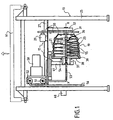
- the installation 11, shown, comprises a support 13 equipped with means for gripping and driving in rotation 17 of a hollow part of revolution 19 to be stripped.
- the wheel or central part of a turbojet turbine In this part is recognized the wheel or central part of a turbojet turbine. It is a piece of complex shape constituted by a plurality of discs 21 welded between they and internally defining coaxial annular cavities 23, axially adjacent, difficult to access. It is known that the heat treatment to which such a piece of titanium alloy is subjected reveals on the surface thereof a contaminated layer commonly known as the "alpha-case layer" which it is desirable to eliminate. Stripping of the interior surface of this room was previously considered impractical.
- the support 13 comprises a kind of gantry 25 carrying at its upper part, fixed to a platform 27, all the means (motor and electromechanical components) for gripping and driving in rotation of the part 19. More specifically, a electric motor 29 drives a support 31 of horizontal axis, carried by a post 32 extending under the platform 27. The support 31 is driven through a set of pinions 33. This support is shaped and dimensioned to fit at one end 36 of the piece. Said support 31 is widely perforated so as not to impede the circulation of a liquid inside the room, in particular a stripping product or a neutralizing or rinsing product.
- a non-motorized rotating member 37 carries three arms 38 that fit on the other end 39 of the part.
- the rotating element is carried by a vertical upright 41 mounted under the platform 27.
- the assembly moves axially to allow the establishment of the part.
- Said support 31 and said rotating element 37 admit the same horizontal axis.
- the piece is held together by being centered by the two circular ends 36 and 39. It can therefore rotate about its own axis of rotation placed in a horizontal position.
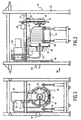
- the part is brought under the gantry 25 while being carried by a forklift truck 46 ( Figures 2 and 3 ) and it is placed between the support 31 and the arms 38. It can therefore be rotated by the motor 29.
- the platform 27 also carries a pump 50 whose input 51 is connected to a conduit whose end 53 is arranged axially (x'x axis) and connected to a collector 54, rigid and removable, may be installed axially inside the room, as shown.
- Flexible suction ducts 55 are connected to this manifold 54.
- Each duct 55 is immersed in one of the cavities 23 when the collector 54 and the part 19 are in place on the support 13, as can be seen on FIG. figure 1 .
- the length of a conduit depends on the corresponding cavity so that its lower end is in the vicinity of the inner wall of the part in its most deeply submerged part, that is to say at the bottom of said corresponding cavity .
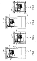
- the pumping means (50, 54, 55) are adapted to continuously pick up the etching product inside the part and at the bottom of each cavity, when said part is partially immersed in a tank 59 of stripper ( figure 5 ). If the piece to be stripped was of another nature and did not include, in particular, several cavities, the suction system inside the room could be simplified and include, for example, only one flexible duct diving into the deepest part.
- a level detector 60 is placed on the gantry and the installation comprises means for adjusting the position of the support 13 (in height) so that said part is partially immersed to a predetermined height, for example, according to the example, up to its axis of rotation x'x.
- lifting means 61 for example part of a crane or the like, installed on the site.
- Said lifting means make it possible to adjust the position of the support 13 and consequently of the part 19 in the tank; they are for this purpose controlled by the level detector 60, which is fixed on the support at a location such that it detects the surface of the pickling product bath when the workpiece is immersed substantially up to the x'x axis.
- the lifting means can be slaved to the detected level to maintain the level detector 60 on the surface of the stripper bath.
- the installation comprises means for maintaining a substantially constant level of stripping product relative to said workpiece.
- the pump 50 is arranged to continuously recycle the pickling product in the tank, outside the part 19.
- a conduit 56 connected to the discharge outlet 52 pump plunges into the tank.
- This recycling makes it possible in practice to maintain the level of stripper product at a constant level in the tank when the support 13 has been immersed in it at a depth determined by the level detector 60.
- the stripper product is pump permanently in the cavities 23 and the bottom thereof, then recycled to the tank outside the room, the activity of the etchant product is maintained homogeneous in all points of the tank.
- the necessary treatment time taking into account the activity of the stripping product (which gradually wears out), it suffices to strip beforehand a specimen which has undergone the same heat treatment as the workpiece and to deduce from it a stripping time. for said piece.
- suction ducts 55 are provided with calibrated flow restrictions 65 (upstream of the manifold 54), the section of each restriction being calculated as a function of the volume of the cavity in which the suction duct plunges. corresponding. This makes it possible to keep the level of stripping product constant in the part itself, in particular at the end of stripping during the time when said part is extracted from the tank and continues to be emptied.
- the pumping is balanced between the cavities, which makes it possible to standardize the stripping in these cavities.
- the installation also comprises a tank of neutralizing product 62, located near the tank 59 and means for transferring the piece 19 (in this case, here, the entire piece and the frame 25) from the tank 59 up to the tank 62.
- a tank of neutralizing product 62 located near the tank 59 and means for transferring the piece 19 (in this case, here, the entire piece and the frame 25) from the tank 59 up to the tank 62.
- These means are constituted by the lifting means 61 previously mentioned.
- the etchant is a mixture of nitric acid and hydrofluoric acid.
- the neutralizing product is water.
- Stripping takes place externally and internally, as shown on the figure 5 with permanent recycling of the pumped cleaner product in the cavities.
- the flow rates of stripping product taken from the cavities are adjusted relative to each other substantially in proportion to the respective volumes of these cavities. This adjustment of the flow rates is obtained thanks to the flow restrictions 65, which are differently calibrated.
- the piece of bath is extracted by raising again the support 13 while continuing the pumping inside the room so that the level of stripping product remaining inside the room decreases gradually through pumping but remains substantially equal in all cavities.
- the part is completely extracted and emptied of the paint remover ( figure 6 ) it is transferred to the tank 62 of neutralizing product and again immersed in it.
- the rotation of the part is advantageously continued throughout the rinsing phase, as is the recycling.
Description
L'invention se rapporte à un procédé de décapage d'une pièce creuse de révolution, notamment une pièce creuse de grandes dimensions, comme par exemple la roue d'une turbine comportant des cavités annulaires séparées par des disques soudés entre eux. Le domaine d'application privilégié de l'invention concerne la dissolution chimique de la couche contaminée riche en oxygène, communément appelée couche « alpha-case » qui se forme sur une telle pièce en alliage de titane, lors du traitement thermique de celle-ci.The invention relates to a method of pickling a hollow part of revolution, in particular a hollow part of large dimensions, such as for example the wheel of a turbine having annular cavities separated by discs welded together. The preferred field of application of the invention relates to the chemical dissolution of the contaminated layer rich in oxygen, commonly called "alpha-case" layer which is formed on such a titanium alloy part, during the heat treatment thereof .
Une roue de turbine en alliage de titane du genre indiqué ci-dessus est réputée difficile d'accès intérieurement compte tenu de la pluralité de cavités annulaires adjacentes définies dans celle-ci entre les disques, soudés ensemble, qui la constitue. Le traitement thermique nécessaire à l'élaboration de cette pièce a pour conséquence de faire apparaître à la surface de celle-ci (extérieurement comme intérieurement) une couche contaminée de quelques dizaines de microns d'épaisseur, riche en oxygène appelée « couche alpha-case ». Actuellement, on se contente de décaper l'extérieur de la pièce, le décapage intérieur ayant été jusqu'à présent considéré comme hasardeux.A titanium alloy turbine wheel of the type indicated above is deemed difficult to access internally, given the plurality of adjacent annular cavities defined therein between the discs, welded together, which constitutes it. The heat treatment required for the development of this part has the effect of revealing on the surface thereof (externally as well as internally) a contaminated layer of a few tens of microns thick, rich in oxygen called "alpha-case layer ". Currently, we are stripping the outside of the room, the interior stripping has so far been considered hazardous.
Or, la présence de cette couche contaminée est à l'origine de la formation de fissures qui réduit considérablement la durée de vie de la pièce.However, the presence of this contaminated layer is at the origin of the formation of cracks which significantly reduces the service life of the part.
L'invention propose un procédé de décapage permettant de dissoudre la couche contaminée, simultanément à l'extérieur comme à l'intérieur, en faisant en sorte que la dissolution chimique se produise uniformément.The invention provides a pickling method for dissolving the contaminated layer simultaneously, both externally and internally, so that chemical dissolution occurs uniformly.
Plus particulièrement, l'invention concerne donc un procédé de décapage d'une pièce creuse de révolution comportant une pluralité de cavités annulaires coaxiales, adjacentes axialement comprenant les étapes consistant à faire tourner ladite pièce autour de son axe de rotation orienté horizontalement, à immerger partiellement ladite pièce dans une cuve remplie de produit décapant de façon que celui-ci pénètre à l'intérieur de ladite pièce et à faire tourner ladite pièce pendant ledit décapage, caractérisé en ce qu'il comporte les étapes consistant à pomper en permanence le produit décapant à l'intérieur de ladite pièce tout en maintenant sensiblement constant le niveau de produit décapant par rapport à ladite pièce, à recycler le produit décapant dans ladite cuve, en le réintroduisant dans celle-ci à l'extérieur de ladite pièce, le pompage étant opéré en prélevant le produit décapant dans lesdites cavités tout en ajustant les débits entre eux, sensiblement proportionnellement aux volumes respectifs de ces cavités.More particularly, the invention therefore relates to a method of stripping a hollow part of revolution comprising a plurality of axially adjacent coaxial annular cavities comprising the steps of rotating said part about its axis of rotation oriented horizontally, to partially immerse. said piece in a vat filled with stripping product so that it penetrates inside said part and to rotate said part during said stripping, characterized in that it comprises the steps of constantly pumping the stripping product inside of said part while maintaining substantially constant the level of stripping product with respect to said part, recycling the stripping product into said tank, by reintroducing it into the latter outside said part, the pumping being carried out by taking the stripping product in said cavities while adjusting the flow rates between them, substantially proportionally to the respective volumes of these cavities.
Le fait d'immerger partiellement la pièce tout en la faisant tourner permet d'uniformiser la profondeur de décapage sur toute la surface de la pièce, à l'intérieur comme à l'extérieur. En particulier, cette solution est préférable à une simple immersion totale de la pièce dans le bain de produit décapant, impraticable en pratique, en raison des bulles d'air qui restent emprisonnées à l'intérieur de la pièce.Partially immersing the workpiece while rotating it allows the pickling depth to be uniform across the entire surface of the workpiece, both indoors and outdoors. In particular, this solution is preferable to a simple total immersion of the room in the bath of cleaning product, impractical in practice, because of the air bubbles that remain trapped inside the room.
Par exemple, on peut immerger la pièce sensiblement jusqu'à son axe de rotation.For example, one can immerse the piece substantially to its axis of rotation.
De cette façon, le renouvellement du produit décapant à l'intérieur des cavités s'opère régulièrement, le produit ayant à tout moment la même efficacité (ou pour ainsi dire, le même degré d'épuisement) dans toutes les cavités. Par exemple, on peut prévoir plusieurs conduits de pompage plongeant respectivement dans les cavités, les débits étant ajustés par des restrictions d'écoulement différemment calibrées.In this way, the renewal of the stripping product inside the cavities takes place regularly, the product having at all times the same efficiency (or, as it were, the same degree of exhaustion) in all the cavities. For example, there may be several pumping ducts respectively dipping into the cavities, the flow rates being adjusted by differently calibrated flow restrictions.
A la fin du décapage, la pièce est extraite du bain de produit décapant tout en poursuivant le pompage à l'intérieur de celle-ci. La rotation est de préférence poursuivie pendant l'extraction de la pièce. L'extraction de la pièce s'opère en un temps relativement bref de l'ordre de 30 secondes. Puis, la pièce est transportée vers un bain de produit neutralisant et plongée dans celui-ci. La rotation est de préférence poursuivie pendant cette phase de rinçage. Le produit neutralisant peut par exemple être de l'eau. L'élimination de la couche contaminée s'opère à l'aide d'un produit décapant constitué, par exemple, par un mélange d'acide nitrique et d'acide fluorhydrique.At the end of the stripping, the piece is extracted from the pickling product bath while continuing the pumping inside thereof. Rotation is preferably continued during part extraction. The extraction of the part takes place in a relatively short time of the order of 30 seconds. Then, the piece is transported to a bath of neutralizing product and immersed in it. Rotation is preferably continued during this rinsing phase. The neutralizing product may for example be water. The removal of the contaminated layer is carried out using a stripping product consisting, for example, of a mixture of nitric acid and hydrofluoric acid.
L'invention concerne également une installation de décapage d'une pièce creuse de révolution, ayant une pluralité de cavités annulaires coaxiales, adjacentes axialement, comportant un support équipé de moyens de préhension et d'entraînement en rotation de ladite pièce, agencés pour la maintenir et l'entraîner en rotation autour de son axe de rotation orienté horizontalement, une cuve de produit décapant, des moyens pour abaisser ladite pièce dans ladite cuve et pour l'immerger partiellement dans ledit produit décapant, caractérisée en ce qu'elle comporte des moyens de pompage pour prélever en permanence du produit décapant à l'intérieur de ladite pièce et des moyens pour maintenir un niveau sensiblement constant de produit décapant par rapport à ladite pièce. et en ce que lesdits moyens de pompage comportent plusieurs conduits d'aspiration dont l'extrémité se situe au voisinage de la paroi intérieure de ladite pièce dans sa partie la plus profondément immergée et plongeant respectivement dans lesdites cavités.The invention also relates to a pickling installation of a hollow part of revolution, having a plurality of coaxial annular cavities, axially adjacent, comprising a support provided with means for gripping and driving in rotation of said part, arranged to maintain it. and driving it in rotation about its horizontally oriented axis of rotation, a tank of stripping product, means for lowering said piece in said tank and for partially immersing it in said stripping product, characterized in that it comprises means pumping apparatus for continuously removing stripper material within said workpiece and means for maintaining a substantially constant level of stripper material relative to said workpiece. and in that said pumping means comprise a plurality of suction conduits whose end is in the vicinity of the inner wall of said part in its most deeply immersed part and plunging respectively into said cavities.
La sortie de refoulement des moyens de pompage est agencée pour réintroduire le produit pompé dans la cuve, à l'extérieur de la pièce.The discharge outlet of the pumping means is arranged to reintroduce the pumped product into the tank, outside the room.
La pièce peut notamment être une roue de rotor à disques soudés.The part may in particular be a rotor wheel with welded disks.
Pour faciliter la mise en place du système d'aspiration, les conduits d'aspiration sont des conduits souples communiquant avec un collecteur relié à une même pompe. Ces conduits d'aspiration peuvent être munis de restrictions d'écoulement calibrées. Dans ce cas la section de chaque restriction est calculée en fonction du volume de la cavité dans laquelle plonge le conduit d'aspiration correspondant.To facilitate the installation of the suction system, the suction ducts are flexible ducts communicating with a manifold connected to the same pump. These suction ducts may be provided with calibrated flow restrictions. In this case the section of each restriction is calculated as a function of the volume of the cavity into which the corresponding suction duct plunges.
L'installation peut aussi comporter une cuve de produit neutralisant et des moyens pour transférer la pièce de la cuve de produit décapant jusqu'à la cuve de produit neutralisant.The installation may also include a tank of neutralizing product and means for transferring the part of the cleaner tank to the tank of neutralizing product.
L'invention sera mieux comprise et d'autres avantages de celle-ci apparaîtront plus clairement à la lumière de la description qui va suivre d'une installation de décapage conforme à son principe, donnée uniquement à titre d'exemple et faite en référence aux dessins annexés dans lesquels :
- fa
figure 1 est une vue schématique en élévation et en coupe partielle d'une partie de l'installation conforme à l'invention ; - la
figure 2 est une vue analogue à lafigure 1 illustrant plus particulièrement la mise en place de la pièce dans l'installation de décapage ; - la
figure 3 est une vue selon la flèche III de lafigure 2 ; et - les
figures 4 à 7 sont des vues schématiques à plus petite échelle de la même instillation, illustrant différentes opérations du processus de décapage.
- fa
figure 1 is a schematic view in elevation and in partial section of a part of the installation according to the invention; - the
figure 2 is a view similar to thefigure 1 illustrating more particularly the placement of the part in the stripping plant; - the
figure 3 is a view along arrow III of thefigure 2 ; and - the
Figures 4 to 7 are schematic views on a smaller scale of the same instillation, illustrating different operations of the stripping process.
L'installation 11, représentée comporte un support 13 équipé de moyens de préhension et d'entraînement en rotation 17 d'une pièce creuse de révolution 19 à décaper. On reconnaît dans cette pièce la roue ou partie centrale d'une turbine de turbo réacteur. Il s'agit d'une pièce de forme complexe constituée par une pluralité de disques 21 soudés entre eux et définissant intérieurement des cavités annulaires coaxiales 23, adjacentes axialement, difficiles d'accès. On sait que le traitement thermique auquel on soumet une telle pièce en alliage de titane fait apparaître à la surface de celle-ci une couche contaminée couramment appelée « couche alpha-case » qu'il est souhaitable d'éliminer. Le décapage de la surface intérieure de cette pièce était jusqu'à présent considéré comme impraticable.The
Le support 13 comporte une sorte de portique 25 portant à sa partie supérieure, fixés à une plate-forme 27, tous les moyens (composants moteurs et électromécaniques) pour la préhension et l'entraînement en rotation de la pièce 19. Plus précisément, un moteur électrique 29 entraîne un support 31 d'axe horizontal, porté par un montant 32 s'étendant sous la plate-forme 27. Le support 31 est entraîné par l'intermédiaire d'un jeu de pignons 33. Ce support est conformé et dimensionné pour s'adapter à une extrémité 36 de la pièce. Ledit support 31 est largement ajouré pour ne pas entraver la circulation d'un liquide à l'intérieur de la pièce, notamment un produit de décapage ou un produit neutralisant ou de rinçage. Un élément tournant 37 non motorisé porte trois bras 38 venant s'adapter à l'autre extrémité 39 de la pièce. L'élément tournant est porté par un montant vertical 41 monté sous la plate-forme 27. L'ensemble se déplace axialement pour permettre la mise en place de la pièce. Ledit support 31 et ledit élément tournant 37 admettent le même axe horizontal. Une fois mise en place, la pièce est maintenue entre eux en étant centrée par les deux extrémités circulaires 36 et 39. Elle peut donc tourner autour de son propre axe de rotation placé en position horizontale. Avant la mise en oeuvre du décapage, la pièce est amenée sous le portique 25 en étant portée par un chariot élévateur 46 (
La plate-forme 27 porte aussi une pompe 50 dont l'entrée 51 est connectée à un conduit dont l'extrémité 53 est agencée axialement (axe x'x) et raccordée à un collecteur 54, rigide et démontable, susceptible d'être installé axialement à l'intérieur de la pièce, comme représenté. Des conduits d'aspiration 55, souples, sont raccordés à ce collecteur 54. Chaque conduit 55 plonge dans l'une des cavités 23 lorsque le collecteur 54 et la pièce 19 sont en place sur le support 13, comme visible sur la
De préférence, l'installation comporte des moyens pour maintenir un niveau sensiblement constant de produit décapant par rapport à ladite pièce. Comme les moyens de pompage prélèvent du produit décapant au fond de la pièce, la pompe 50 est agencée pour recycler en permanence le produit décapant dans la cuve, à l'extérieur de la pièce 19. Un conduit 56 connecté à la sortie de refoulement 52 de la pompe plonge dans la cuve. Ce recyclage permet en pratique de maintenir le niveau de produit décapant à un niveau constant dans la cuve dès lors que le support 13 a été plongé dans celle-ci à une profondeur déterminée par le détecteur de niveau 60. Du fait que le produit décapant est pompé en permanence dans les cavités 23 et au fond de celles-ci, puis recyclé dans la cuve à l'extérieur de la pièce, l'activité du produit décapant est maintenue homogène en tous points de la cuve. Pour déterminer le temps de traitement nécessaire en tenant compte de l'activité du produit décapant (lequel s'épuise progressivement) il suffit de décaper au préalable une éprouvette ayant subi le même traitement thermique que la pièce et d'en déduire un temps de décapage pour ladite pièce.Preferably, the installation comprises means for maintaining a substantially constant level of stripping product relative to said workpiece. As the pumping means take off the etching product at the bottom of the part, the
De plus, au moins certains conduits d'aspiration 55 sont munis de restrictions d'écoulement calibrées 65 (en amont du collecteur 54), la section de chaque restriction étant calculée en fonction du volume de la cavité dans laquelle plonge le conduit d'aspiration correspondant. Ceci permet de maintenir constant le niveau de produit décapant dans la pièce elle-même, notamment à la fin du décapage pendant le temps où ladite pièce est extraite de la cuve et continue d'être vidée.In addition, at least some
Pendant le traitement lui-même, le pompage est équilibré entre les cavités, ce qui permet encore d'uniformiser le décapage dans celles-ci.During the treatment itself, the pumping is balanced between the cavities, which makes it possible to standardize the stripping in these cavities.
L'installation comporte aussi une cuve de produit neutralisant 62, située à proximité de la cuve 59 et des moyens pour transférer la pièce 19 (en l'occurrence, ici, l'ensemble de la pièce et du portique 25) depuis la cuve 59 jusqu'à la cuve 62. Ces moyens sont ici constitués par les moyens de levage 61 précédemment mentionnés.The installation also comprises a tank of neutralizing
Dans l'exemple décrit où la pièce est en alliage de titane, le produit décapant est un mélange d'acide nitrique et d'acide fluorhydrique. Le produit neutralisant est de l'eau.In the example described where the piece is made of titanium alloy, the etchant is a mixture of nitric acid and hydrofluoric acid. The neutralizing product is water.
La mise en oeuvre du procédé découle avec évidence de la description qui précède. On commence par mettre en place la pièce sur le support 13, comme illustré aux
Claims (14)
- A method of pickling a hollow part (19) in the form of a body of revolution, containing a plurality of adjacent annular activities (23) coaxial about said axis, comprising the steps consisting in rotating said part about its axis of rotation (x'x) in a horizontal orientation, in partially immersing said part in a vessel (59) filled with pickling composition so that the composition penetrates into the inside of said part and in causing said part to rotate during pickling, characterized in that it comprises steps consisting in continuously pumping (50) the pickling composition from the inside of said part while maintaining the level of pickling substance substantially constant relative to said part, in that the pickling composition is recycled into said vessel, by being reintroduced therein outside said part, the pumping being performed by taking the pickling composition from within said cavities while adjusting the flow rates relative to one another substantially in proportion to the respective volumes of the cavities.
- A method according to claim 1, characterized in that said part is immersed substantially up to its axis of rotation (x'x).
- A method according to any preceding claim, characterized in that it is implemented for pickling a rotor wheel made up of welded-together disks.
- A method according to claim 3, characterized in that the pickling composition is pumped via a plurality of suction ducts (55) dipping into respective ones of said cavities, the flow rates in the suction ducts being adjusted by flow constrictions (65) of different bore sizes.
- A method according to any preceding claim, characterized in that, at the end of said pickling, the part is extracted from the bath of pickling composition while continuing to pump from the inside of said part.
- A method according to any preceding claim, characterized in that, after the part has been extracted from the bath of pickling composition, it is dipped into a bath of neutralizing composition.
- A method according to any preceding claim, characterized in that said pickling composition is a mixture of nitric acid and hydrofluoric acid.
- A method according to claim 6, characterized in that said neutralizing composition is water.
- An installation for pickling a part in the form of a body of revolution, containing a plurality of adjacent annular cavities (23) coaxial about said axis, comprising a support (13) fitted with means (17) for holding said part and for driving it in rotation, said means being arranged to hold and rotate the part about its axis of rotation (x'x) in a horizontal orientation, a vessel of pickling composition (59), means for lowering said part into said vessel and for partially immersing it in said pickling composition, characterized in that it comprises pump means (50, 54, 55) for continuously taking pickling composition from the inside of said part, and means (50, 54, 55, 60) for maintaining a substantially constant level of pickling composition relative to said part and in that said pump means include a plurality of suction ducts (55) dipping into respective ones of said cavities and having ends situated in the vicinity of the inside wall of said part (19) in its most-deeply immersed portion.
- An installation according to claim 9, characterized in that it includes a level sensor (60) and means for adjusting the position of said support (13) in such a manner that said part (19) is partially immersed up to a predetermined depth, for example substantially up to its axis of rotation (x', x).
- An installation according to any one of claims 9 or 10, characterized in that the delivery outlet (52) of the pump means is arranged to recycle (56) the pickling composition in the vessel, outside said part.
- An installation according to claim 9, characterized in that said suction ducts (55) are flexible hoses communicating with a collector (54) connected to a pump.
- An installation according to any one of claims 9 to 12, characterized in that at least some of the suction ducts (55) are provided with calibrated flow constrictions (65), with the section of each constriction being determined as a function of the volume of the cavity in which the corresponding suction duct dips.
- An installation according to any one of claims 9 to 13, characterized in that it includes a vessel (62) of neutralizing composition and means (61) for transferring the part from the vessel of pickling composition (59) to the vessel of neutralizing composition (62).
Applications Claiming Priority (2)
| Application Number | Priority Date | Filing Date | Title |
|---|---|---|---|
| FR0405332A FR2870142B1 (en) | 2004-05-17 | 2004-05-17 | METHOD FOR REMOVING A REVOLUTION HOLLOW PIECE AND DEVICE IMPLEMENTING SAID METHOD |
| FR0405332 | 2004-05-17 |
Publications (2)
| Publication Number | Publication Date |
|---|---|
| EP1598447A1 EP1598447A1 (en) | 2005-11-23 |
| EP1598447B1 true EP1598447B1 (en) | 2012-06-20 |
Family
ID=34942294
Family Applications (1)
| Application Number | Title | Priority Date | Filing Date |
|---|---|---|---|
| EP05291048A Active EP1598447B1 (en) | 2004-05-17 | 2005-05-16 | Process and apparatus for pickling hollow rotationally symmmetrical workpiece |
Country Status (8)
| Country | Link |
|---|---|
| US (1) | US7703463B2 (en) |
| EP (1) | EP1598447B1 (en) |
| JP (1) | JP4619194B2 (en) |
| CN (1) | CN1699626B (en) |
| CA (1) | CA2507164C (en) |
| ES (1) | ES2387986T3 (en) |
| FR (1) | FR2870142B1 (en) |
| RU (1) | RU2367527C2 (en) |
Families Citing this family (8)
| Publication number | Priority date | Publication date | Assignee | Title |
|---|---|---|---|---|
| FR2961598B1 (en) * | 2010-06-21 | 2012-07-27 | Snecma | PROCESS FOR CHECKING A TITANIUM OR TITANIUM ALLOY FOR THE DETECTION OF MACHINING DEFECTS |
| CN102311231A (en) * | 2011-08-06 | 2012-01-11 | 海宁伊满阁太阳能科技有限公司 | Device for pickling frosting by using vacuum heat-collecting tube and cover glass tube |
| FR3056605B1 (en) * | 2016-09-29 | 2020-12-18 | Safran Aircraft Engines | DEVICE FOR CHEMICAL TREATMENT OF A TURBOMACHINE PART EQUIPPED WITH A METAL SURFACE ELEMENT |
| FR3084673A1 (en) * | 2018-08-02 | 2020-02-07 | Safran Aircraft Engines | DEVICE FOR DIPPING AT LEAST ONE PART OF A TURBOMACHINE IN A CHEMICAL STRIPPING BATH |
| CN110129809B (en) * | 2019-04-09 | 2021-04-23 | 上海老凤祥首饰研究所有限公司 | Surface nondestructive treatment process for thousand pure gold double-set necklace |
| CN112030174A (en) * | 2020-09-04 | 2020-12-04 | 海盐金鼎钢管股份有限公司 | Steel pipe acid dip pickle that pickling is efficient |
| CN114000158B (en) * | 2021-10-28 | 2023-11-28 | 泰安航天特种车有限公司 | Automatic pickling equipment suitable for steel pipe inner wall |
| CN114011790A (en) * | 2021-11-25 | 2022-02-08 | 桂林电子科技大学 | Automatic pickling processing equipment for mechanical parts |
Citations (1)
| Publication number | Priority date | Publication date | Assignee | Title |
|---|---|---|---|---|
| US3420712A (en) * | 1964-07-10 | 1969-01-07 | Parsons Corp | Method for treating elongated metal workpieces with a succession of treating liquids |
Family Cites Families (15)
| Publication number | Priority date | Publication date | Assignee | Title |
|---|---|---|---|---|
| BE480102A (en) * | 1944-01-06 | |||
| GB731569A (en) * | 1953-04-24 | 1955-06-08 | Alfred George Honey | Improvements relating to apparatus for cleaning ball or roller bearings |
| US2849097A (en) * | 1954-08-05 | 1958-08-26 | Udylite Corp | Automatic apparatus for chemical treatment of metal articles in bulk |
| GB1023402A (en) * | 1964-02-29 | 1966-03-23 | A T Juniper Ltd | Improvements in or relating to apparatus for dispensing liquid under pressure for use for example in the washing of compressor blades of gas turbine engines |
| SE387720B (en) * | 1974-12-30 | 1976-09-13 | Stal Laval Turbin Ab | WASHER FOR WASH STEP COMPRESSOR |
| JPS52130155A (en) * | 1976-04-26 | 1977-11-01 | Hitachi Ltd | Method of and apparatus for pickling elongated small-diametered metal tube |
| JP2604650B2 (en) * | 1991-06-07 | 1997-04-30 | 本田技研工業株式会社 | Surface treatment method |
| CN2139128Y (en) * | 1992-06-01 | 1993-07-28 | 天津市自行车钢材改制厂 | Single-shaft machine for pickling band steel |
| US5318683A (en) * | 1993-02-01 | 1994-06-07 | Quad/Tech, Inc. | Electrodeposition system |
| US5716509A (en) * | 1994-02-15 | 1998-02-10 | Ecograph Ag | Process and device for the electrolytic surface coating of workpieces |
| JPH08101206A (en) * | 1994-09-29 | 1996-04-16 | Horiba Ltd | Cleaning nozzle and cleaning method of container using it |
| WO1996015863A1 (en) * | 1994-11-22 | 1996-05-30 | United Technologies Corporation | Cleaning method for turbine airfoils by ultrasonics |
| DE19839479A1 (en) * | 1998-08-29 | 2000-03-02 | Schaeffler Waelzlager Ohg | Chemical or electrochemical treatment of an axisymmetric hollow component involves holding the component in a rotating unit so that a circumferential section of the component is dipped into the treatment bath |
| US6503334B2 (en) * | 2001-03-14 | 2003-01-07 | Hydrochem Industrial Services, Inc. | Forced mist cleaning of combustion turbines |
| DE10308731B4 (en) * | 2003-02-28 | 2005-09-01 | Contitech Luftfedersysteme Gmbh | Method and device for galvanic coating of hollow bodies |
-
2004
- 2004-05-17 FR FR0405332A patent/FR2870142B1/en active Active
-
2005
- 2005-05-11 CA CA2507164A patent/CA2507164C/en active Active
- 2005-05-11 US US11/126,283 patent/US7703463B2/en active Active
- 2005-05-12 JP JP2005139595A patent/JP4619194B2/en active Active
- 2005-05-16 RU RU2005114871/12A patent/RU2367527C2/en active
- 2005-05-16 ES ES05291048T patent/ES2387986T3/en active Active
- 2005-05-16 EP EP05291048A patent/EP1598447B1/en active Active
- 2005-05-17 CN CN2005100728895A patent/CN1699626B/en active Active
Patent Citations (1)
| Publication number | Priority date | Publication date | Assignee | Title |
|---|---|---|---|---|
| US3420712A (en) * | 1964-07-10 | 1969-01-07 | Parsons Corp | Method for treating elongated metal workpieces with a succession of treating liquids |
Also Published As
| Publication number | Publication date |
|---|---|
| RU2005114871A (en) | 2006-11-20 |
| CA2507164A1 (en) | 2005-11-17 |
| CA2507164C (en) | 2012-10-16 |
| JP2005329402A (en) | 2005-12-02 |
| US7703463B2 (en) | 2010-04-27 |
| ES2387986T3 (en) | 2012-10-05 |
| RU2367527C2 (en) | 2009-09-20 |
| EP1598447A1 (en) | 2005-11-23 |
| FR2870142B1 (en) | 2007-02-09 |
| CN1699626B (en) | 2010-06-09 |
| FR2870142A1 (en) | 2005-11-18 |
| US20050252530A1 (en) | 2005-11-17 |
| CN1699626A (en) | 2005-11-23 |
| JP4619194B2 (en) | 2011-01-26 |
Similar Documents
| Publication | Publication Date | Title |
|---|---|---|
| EP1598447B1 (en) | Process and apparatus for pickling hollow rotationally symmmetrical workpiece | |
| EP2872878B1 (en) | Device for spraying a dye penetrant onto a workpiece | |
| EP2678120B1 (en) | Equipment and method for depositing a film of ordered particles on a moving substrate | |
| FR2961598A1 (en) | Method for controlling titanium or part e.g. drum of compressor of turboshaft engine, to detect machining defects of part, involves inspecting surfaces of titanium or titanium alloy part for detecting machining defects | |
| EP1305147B1 (en) | Method and device for recycling tyres | |
| EP3408589B1 (en) | Installation for the automated straightening of a spark plug electrode and associated automated straightening method | |
| EP0030884B1 (en) | Apparatus for treating compounds in a liquid | |
| FR3085598A1 (en) | NOMAD PROCESS FOR THE SOFT EXTRACTION OF GRAPE FILM CONSTITUENTS IN THE RED VINIFICATION MACERATION PHASE OR WHITE WINE BREWING AT LOW PRESSURE OF CARBON GAS OR AIR | |
| FR2975072A1 (en) | METHOD FOR DISCHARGING LIQUID FROM A TANK OF A DISASTER VESSEL | |
| FR2771654A1 (en) | MULTI-FUNCTION METHOD AND APPARATUS FOR THE MAINTENANCE OF METASTABLE LIQUIDS | |
| CA1219813A (en) | Evacuation and de-aeration process and device for sludges in an etching bath | |
| FR2795979A1 (en) | Method and machine for the treatment of small components with a treatment fluid, notably for coating or the chemical deburring of such components | |
| FR3067344B1 (en) | DECONTAMINATION FACILITY COMPRISING A THERMAL TREATMENT TANK AND ASSOCIATED DECONTAMINATION METHOD | |
| EP1733868A1 (en) | Device and process for cooling of a core | |
| FR2878531A1 (en) | Crumbling a marc cap (sic) comprises placing a grape in a storage, allowing the fermentation of the grape, crumbling the cap resulting from separation of the solid and liquid phases and injecting a gas into the storage | |
| EP1629874B1 (en) | Apparatus for sewage treatment plants for extracting sludge | |
| EP0956005B1 (en) | Device and method for making a segmented tubular capsule containing a biologically active medium | |
| EP4170316A1 (en) | Sample collection apparatus and sample collection device | |
| WO2001087496A1 (en) | Method for recuperating a coating fluid, such as paint, contained in an installation | |
| FR2547596A1 (en) | Plant for the treatment of mechanical components and more particularly metal quenching plant | |
| EP1808415A1 (en) | Device for electromagnetic sludge removal | |
| FR2481716A1 (en) | Electrochemical cell, esp. for silver recovery - from fixer soln., has cylindrical electrodes between which soln. is circulated | |
| EP0943375A1 (en) | Method and installation for soil remediation | |
| EP0192509A1 (en) | Method and device for the preparation of milk used in the production of cheese | |
| EP2806053A2 (en) | Electrolyser, anode for said electrolyser and electrolysis method in said electrolyser |
Legal Events
| Date | Code | Title | Description |
|---|---|---|---|
| PUAI | Public reference made under article 153(3) epc to a published international application that has entered the european phase |
Free format text: ORIGINAL CODE: 0009012 |
|
| 17P | Request for examination filed |
Effective date: 20050523 |
|
| AK | Designated contracting states |
Kind code of ref document: A1 Designated state(s): AT BE BG CH CY CZ DE DK EE ES FI FR GB GR HU IE IS IT LI LT LU MC NL PL PT RO SE SI SK TR |
|
| AX | Request for extension of the european patent |
Extension state: AL BA HR LV MK YU |
|
| AKX | Designation fees paid |
Designated state(s): AT BE BG CH CY CZ DE DK EE ES FI FR GB GR HU IE IS IT LI LT LU MC NL PL PT RO SE SI SK TR |
|
| 17Q | First examination report despatched |
Effective date: 20070309 |
|
| GRAP | Despatch of communication of intention to grant a patent |
Free format text: ORIGINAL CODE: EPIDOSNIGR1 |
|
| GRAS | Grant fee paid |
Free format text: ORIGINAL CODE: EPIDOSNIGR3 |
|
| GRAA | (expected) grant |
Free format text: ORIGINAL CODE: 0009210 |
|
| AK | Designated contracting states |
Kind code of ref document: B1 Designated state(s): AT BE BG CH CY CZ DE DK EE ES FI FR GB GR HU IE IS IT LI LT LU MC NL PL PT RO SE SI SK TR |
|
| REG | Reference to a national code |
Ref country code: GB Ref legal event code: FG4D Free format text: NOT ENGLISH |
|
| REG | Reference to a national code |
Ref country code: CH Ref legal event code: EP |
|
| REG | Reference to a national code |
Ref country code: AT Ref legal event code: REF Ref document number: 563130 Country of ref document: AT Kind code of ref document: T Effective date: 20120715 |
|
| REG | Reference to a national code |
Ref country code: IE Ref legal event code: FG4D Free format text: LANGUAGE OF EP DOCUMENT: FRENCH |
|
| REG | Reference to a national code |
Ref country code: DE Ref legal event code: R096 Ref document number: 602005034817 Country of ref document: DE Effective date: 20120816 |
|
| REG | Reference to a national code |
Ref country code: SE Ref legal event code: TRGR |
|
| REG | Reference to a national code |
Ref country code: ES Ref legal event code: FG2A Ref document number: 2387986 Country of ref document: ES Kind code of ref document: T3 Effective date: 20121005 |
|
| PG25 | Lapsed in a contracting state [announced via postgrant information from national office to epo] |
Ref country code: LT Free format text: LAPSE BECAUSE OF FAILURE TO SUBMIT A TRANSLATION OF THE DESCRIPTION OR TO PAY THE FEE WITHIN THE PRESCRIBED TIME-LIMIT Effective date: 20120620 Ref country code: FI Free format text: LAPSE BECAUSE OF FAILURE TO SUBMIT A TRANSLATION OF THE DESCRIPTION OR TO PAY THE FEE WITHIN THE PRESCRIBED TIME-LIMIT Effective date: 20120620 |
|
| REG | Reference to a national code |
Ref country code: NL Ref legal event code: VDEP Effective date: 20120620 |
|
| REG | Reference to a national code |
Ref country code: AT Ref legal event code: MK05 Ref document number: 563130 Country of ref document: AT Kind code of ref document: T Effective date: 20120620 |
|
| REG | Reference to a national code |
Ref country code: LT Ref legal event code: MG4D Effective date: 20120620 |
|
| PG25 | Lapsed in a contracting state [announced via postgrant information from national office to epo] |
Ref country code: SI Free format text: LAPSE BECAUSE OF FAILURE TO SUBMIT A TRANSLATION OF THE DESCRIPTION OR TO PAY THE FEE WITHIN THE PRESCRIBED TIME-LIMIT Effective date: 20120620 Ref country code: GR Free format text: LAPSE BECAUSE OF FAILURE TO SUBMIT A TRANSLATION OF THE DESCRIPTION OR TO PAY THE FEE WITHIN THE PRESCRIBED TIME-LIMIT Effective date: 20120921 |
|
| PG25 | Lapsed in a contracting state [announced via postgrant information from national office to epo] |
Ref country code: AT Free format text: LAPSE BECAUSE OF FAILURE TO SUBMIT A TRANSLATION OF THE DESCRIPTION OR TO PAY THE FEE WITHIN THE PRESCRIBED TIME-LIMIT Effective date: 20120620 Ref country code: SK Free format text: LAPSE BECAUSE OF FAILURE TO SUBMIT A TRANSLATION OF THE DESCRIPTION OR TO PAY THE FEE WITHIN THE PRESCRIBED TIME-LIMIT Effective date: 20120620 Ref country code: RO Free format text: LAPSE BECAUSE OF FAILURE TO SUBMIT A TRANSLATION OF THE DESCRIPTION OR TO PAY THE FEE WITHIN THE PRESCRIBED TIME-LIMIT Effective date: 20120620 Ref country code: IS Free format text: LAPSE BECAUSE OF FAILURE TO SUBMIT A TRANSLATION OF THE DESCRIPTION OR TO PAY THE FEE WITHIN THE PRESCRIBED TIME-LIMIT Effective date: 20121020 Ref country code: CZ Free format text: LAPSE BECAUSE OF FAILURE TO SUBMIT A TRANSLATION OF THE DESCRIPTION OR TO PAY THE FEE WITHIN THE PRESCRIBED TIME-LIMIT Effective date: 20120620 Ref country code: EE Free format text: LAPSE BECAUSE OF FAILURE TO SUBMIT A TRANSLATION OF THE DESCRIPTION OR TO PAY THE FEE WITHIN THE PRESCRIBED TIME-LIMIT Effective date: 20120620 Ref country code: CY Free format text: LAPSE BECAUSE OF FAILURE TO SUBMIT A TRANSLATION OF THE DESCRIPTION OR TO PAY THE FEE WITHIN THE PRESCRIBED TIME-LIMIT Effective date: 20120620 |
|
| PG25 | Lapsed in a contracting state [announced via postgrant information from national office to epo] |
Ref country code: PL Free format text: LAPSE BECAUSE OF FAILURE TO SUBMIT A TRANSLATION OF THE DESCRIPTION OR TO PAY THE FEE WITHIN THE PRESCRIBED TIME-LIMIT Effective date: 20120620 Ref country code: PT Free format text: LAPSE BECAUSE OF FAILURE TO SUBMIT A TRANSLATION OF THE DESCRIPTION OR TO PAY THE FEE WITHIN THE PRESCRIBED TIME-LIMIT Effective date: 20121022 |
|
| PG25 | Lapsed in a contracting state [announced via postgrant information from national office to epo] |
Ref country code: NL Free format text: LAPSE BECAUSE OF FAILURE TO SUBMIT A TRANSLATION OF THE DESCRIPTION OR TO PAY THE FEE WITHIN THE PRESCRIBED TIME-LIMIT Effective date: 20120620 |
|
| PLBE | No opposition filed within time limit |
Free format text: ORIGINAL CODE: 0009261 |
|
| STAA | Information on the status of an ep patent application or granted ep patent |
Free format text: STATUS: NO OPPOSITION FILED WITHIN TIME LIMIT |
|
| PG25 | Lapsed in a contracting state [announced via postgrant information from national office to epo] |
Ref country code: DK Free format text: LAPSE BECAUSE OF FAILURE TO SUBMIT A TRANSLATION OF THE DESCRIPTION OR TO PAY THE FEE WITHIN THE PRESCRIBED TIME-LIMIT Effective date: 20120620 |
|
| 26N | No opposition filed |
Effective date: 20130321 |
|
| REG | Reference to a national code |
Ref country code: DE Ref legal event code: R097 Ref document number: 602005034817 Country of ref document: DE Effective date: 20130321 |
|
| PG25 | Lapsed in a contracting state [announced via postgrant information from national office to epo] |
Ref country code: BG Free format text: LAPSE BECAUSE OF FAILURE TO SUBMIT A TRANSLATION OF THE DESCRIPTION OR TO PAY THE FEE WITHIN THE PRESCRIBED TIME-LIMIT Effective date: 20120920 |
|
| BERE | Be: lapsed |
Owner name: SNECMA Effective date: 20130531 |
|
| PG25 | Lapsed in a contracting state [announced via postgrant information from national office to epo] |
Ref country code: MC Free format text: LAPSE BECAUSE OF FAILURE TO SUBMIT A TRANSLATION OF THE DESCRIPTION OR TO PAY THE FEE WITHIN THE PRESCRIBED TIME-LIMIT Effective date: 20120620 |
|
| REG | Reference to a national code |
Ref country code: CH Ref legal event code: PL |
|
| PG25 | Lapsed in a contracting state [announced via postgrant information from national office to epo] |
Ref country code: LI Free format text: LAPSE BECAUSE OF NON-PAYMENT OF DUE FEES Effective date: 20130531 Ref country code: CH Free format text: LAPSE BECAUSE OF NON-PAYMENT OF DUE FEES Effective date: 20130531 |
|
| REG | Reference to a national code |
Ref country code: IE Ref legal event code: MM4A |
|
| PG25 | Lapsed in a contracting state [announced via postgrant information from national office to epo] |
Ref country code: BE Free format text: LAPSE BECAUSE OF NON-PAYMENT OF DUE FEES Effective date: 20130531 |
|
| PG25 | Lapsed in a contracting state [announced via postgrant information from national office to epo] |
Ref country code: IE Free format text: LAPSE BECAUSE OF NON-PAYMENT OF DUE FEES Effective date: 20130516 |
|
| REG | Reference to a national code |
Ref country code: ES Ref legal event code: FD2A Effective date: 20140613 |
|
| PG25 | Lapsed in a contracting state [announced via postgrant information from national office to epo] |
Ref country code: ES Free format text: LAPSE BECAUSE OF NON-PAYMENT OF DUE FEES Effective date: 20130517 |
|
| PG25 | Lapsed in a contracting state [announced via postgrant information from national office to epo] |
Ref country code: TR Free format text: LAPSE BECAUSE OF FAILURE TO SUBMIT A TRANSLATION OF THE DESCRIPTION OR TO PAY THE FEE WITHIN THE PRESCRIBED TIME-LIMIT Effective date: 20120620 |
|
| PG25 | Lapsed in a contracting state [announced via postgrant information from national office to epo] |
Ref country code: HU Free format text: LAPSE BECAUSE OF FAILURE TO SUBMIT A TRANSLATION OF THE DESCRIPTION OR TO PAY THE FEE WITHIN THE PRESCRIBED TIME-LIMIT; INVALID AB INITIO Effective date: 20050516 Ref country code: LU Free format text: LAPSE BECAUSE OF NON-PAYMENT OF DUE FEES Effective date: 20130516 |
|
| REG | Reference to a national code |
Ref country code: FR Ref legal event code: PLFP Year of fee payment: 12 |
|
| REG | Reference to a national code |
Ref country code: FR Ref legal event code: PLFP Year of fee payment: 13 |
|
| REG | Reference to a national code |
Ref country code: FR Ref legal event code: CD Owner name: SAFRAN AIRCRAFT ENGINES, FR Effective date: 20170717 |
|
| REG | Reference to a national code |
Ref country code: FR Ref legal event code: PLFP Year of fee payment: 14 |
|
| PGFP | Annual fee paid to national office [announced via postgrant information from national office to epo] |
Ref country code: IT Payment date: 20230420 Year of fee payment: 19 Ref country code: FR Payment date: 20230420 Year of fee payment: 19 Ref country code: DE Payment date: 20230419 Year of fee payment: 19 |
|
| PGFP | Annual fee paid to national office [announced via postgrant information from national office to epo] |
Ref country code: SE Payment date: 20230419 Year of fee payment: 19 |
|
| PGFP | Annual fee paid to national office [announced via postgrant information from national office to epo] |
Ref country code: GB Payment date: 20230420 Year of fee payment: 19 |