EP1598248A2 - Verfahren und Vorrichtung zum Entfernen von stehenden Flüssigkeiten von flachen, gekrümmten gewölbten, oder strukturierten Oberflächen - Google Patents
Verfahren und Vorrichtung zum Entfernen von stehenden Flüssigkeiten von flachen, gekrümmten gewölbten, oder strukturierten Oberflächen Download PDFInfo
- Publication number
- EP1598248A2 EP1598248A2 EP04014214A EP04014214A EP1598248A2 EP 1598248 A2 EP1598248 A2 EP 1598248A2 EP 04014214 A EP04014214 A EP 04014214A EP 04014214 A EP04014214 A EP 04014214A EP 1598248 A2 EP1598248 A2 EP 1598248A2
- Authority
- EP
- European Patent Office
- Prior art keywords
- handle
- water
- blade
- lip
- flexible
- Prior art date
- Legal status (The legal status is an assumption and is not a legal conclusion. Google has not performed a legal analysis and makes no representation as to the accuracy of the status listed.)
- Granted
Links
Images


Classifications
-
- B—PERFORMING OPERATIONS; TRANSPORTING
- B60—VEHICLES IN GENERAL
- B60S—SERVICING, CLEANING, REPAIRING, SUPPORTING, LIFTING, OR MANOEUVRING OF VEHICLES, NOT OTHERWISE PROVIDED FOR
- B60S3/00—Vehicle cleaning apparatus not integral with vehicles
- B60S3/04—Vehicle cleaning apparatus not integral with vehicles for exteriors of land vehicles
- B60S3/045—Other hand-held cleaning arrangements, e.g. with sponges, brushes, scrapers or the like
-
- A—HUMAN NECESSITIES
- A47—FURNITURE; DOMESTIC ARTICLES OR APPLIANCES; COFFEE MILLS; SPICE MILLS; SUCTION CLEANERS IN GENERAL
- A47L—DOMESTIC WASHING OR CLEANING; SUCTION CLEANERS IN GENERAL
- A47L1/00—Cleaning windows
- A47L1/06—Hand implements
-
- A—HUMAN NECESSITIES
- A47—FURNITURE; DOMESTIC ARTICLES OR APPLIANCES; COFFEE MILLS; SPICE MILLS; SUCTION CLEANERS IN GENERAL
- A47L—DOMESTIC WASHING OR CLEANING; SUCTION CLEANERS IN GENERAL
- A47L13/00—Implements for cleaning floors, carpets, furniture, walls, or wall coverings
- A47L13/10—Scrubbing; Scouring; Cleaning; Polishing
- A47L13/11—Squeegees
-
- B—PERFORMING OPERATIONS; TRANSPORTING
- B29—WORKING OF PLASTICS; WORKING OF SUBSTANCES IN A PLASTIC STATE IN GENERAL
- B29C—SHAPING OR JOINING OF PLASTICS; SHAPING OF MATERIAL IN A PLASTIC STATE, NOT OTHERWISE PROVIDED FOR; AFTER-TREATMENT OF THE SHAPED PRODUCTS, e.g. REPAIRING
- B29C70/00—Shaping composites, i.e. plastics material comprising reinforcements, fillers or preformed parts, e.g. inserts
- B29C70/68—Shaping composites, i.e. plastics material comprising reinforcements, fillers or preformed parts, e.g. inserts by incorporating or moulding on preformed parts, e.g. inserts or layers, e.g. foam blocks
- B29C70/70—Completely encapsulating inserts
-
- B—PERFORMING OPERATIONS; TRANSPORTING
- B29—WORKING OF PLASTICS; WORKING OF SUBSTANCES IN A PLASTIC STATE IN GENERAL
- B29C—SHAPING OR JOINING OF PLASTICS; SHAPING OF MATERIAL IN A PLASTIC STATE, NOT OTHERWISE PROVIDED FOR; AFTER-TREATMENT OF THE SHAPED PRODUCTS, e.g. REPAIRING
- B29C70/00—Shaping composites, i.e. plastics material comprising reinforcements, fillers or preformed parts, e.g. inserts
- B29C70/68—Shaping composites, i.e. plastics material comprising reinforcements, fillers or preformed parts, e.g. inserts by incorporating or moulding on preformed parts, e.g. inserts or layers, e.g. foam blocks
- B29C70/74—Moulding material on a relatively small portion of the preformed part, e.g. outsert moulding
-
- B—PERFORMING OPERATIONS; TRANSPORTING
- B29—WORKING OF PLASTICS; WORKING OF SUBSTANCES IN A PLASTIC STATE IN GENERAL
- B29L—INDEXING SCHEME ASSOCIATED WITH SUBCLASS B29C, RELATING TO PARTICULAR ARTICLES
- B29L2031/00—Other particular articles
- B29L2031/28—Tools, e.g. cutlery
- B29L2031/283—Hand tools
-
- B—PERFORMING OPERATIONS; TRANSPORTING
- B29—WORKING OF PLASTICS; WORKING OF SUBSTANCES IN A PLASTIC STATE IN GENERAL
- B29L—INDEXING SCHEME ASSOCIATED WITH SUBCLASS B29C, RELATING TO PARTICULAR ARTICLES
- B29L2031/00—Other particular articles
- B29L2031/46—Knobs or handles, push-buttons, grips
- B29L2031/463—Grips, handles
Definitions
- the present invention is in the field of car-wash accessories and pertains more particularly to hand-held devices used for removing standing water from automobiles and other vehicles.
- Bottled solutions or treatments are sometimes employed as aids to reducing spotting or staining of an automobiles finish often resulting from standing water.
- the type of water used in washing a car plays a part in possible spotting or staining that may be present on an automobiles finish after a wash. For example, if the water is very hard (has a lot of dissolved minerals) minerals, resultant spotting can be extreme; whereas, if the water is softer, spotting may be lessened.
- These bottled solutions or pastes are designed to reduce spotting via their interaction with the water itself.
- the chamois is a highly flexible section of treated animal skin that has a large absorption capability.
- the chamois is typically used just after the automobile has been rinsed. It is laid out on a surface and pulled in the direction of the user.
- chamois cloths must often be used to completely remove standing water from an automobile finish.
- the chamois is very soft and generally harmless to a paint job or finish, it is possible that unseen dirt or particles left over from the car-wash process get lodged in the chamois and can cause scratches when the chamois is pulled across the surface of an automobile. This can be particularly disturbing for those who own expensive show cars that support special auto paints that may be susceptible to scratching.
- a water-wiping apparatus for wiping standing water from a curved surface comprising a flexible panel of a first height, with an upper long edge and a lower long edge, a flexible handle attached along the upper long edge, and a lip formed along the lower edge, extending to one side of the flexible panel and ending in a sharp line at the end away from the flexible panel.
- the flexible handle is formed from sanoprene. Also in one embodiment the flexible handle is molded in two parts. In some embodiments the flexible panel has a groove along the upper long edge, and the two parts snap together, capturing the flexible panel by the groove. In some cases there is a rigid spine molded within the flexible handle.
- the lip has a triangular cross-section in a plane cutting the panel orthogonal to the length and parallel to the height. Also in some embodiments the lip joins the flexible panel at an angle equal or less than thirty degrees. The lip may extend to both sides of the flexible panel.
- a method for forming a handle on a water wiper blade insert having an upper long edge with a groove comprising steps of (a) placing the blade insert in a mold having a volume in the desired shape of the handle, with the groove in the volume; and (b) filling the volume with a flexible molding material. In some embodiments there is a further step for placing a stiffening element in the volume before filling the volume with the molding material.
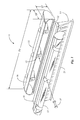
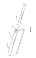
- Handle sections 15 and 17 are designed to fit together to form a handle grip that retains the wiper blade, is comfortable to hold, and is of light weight. In a preferred embodiment, special texture areas are provided around the outer edges of each handle section , although this is not required. Recesses may be molded into handle sections 15 and 17 for the purpose of supporting decals, logos, and the like.
- handle section 15 has assembly brackets such as bracket 14 that are designed to accept rivets such as rivet 19 that are to be inserted through access points shown in handle section 17, such as the access point shown roughly in line with rivet 19 and bracket 14 illustrated by the directional arrows.
- Bracket 14 may be formed in the molding process or may be mounted to handle section 15 after molding.
- Bracket 14 may be fabricated from aluminum, sheet metal, or any other suitable material known in the art and of suitable strength to provide a secure attachment.
- a one-piece handle may be provided with a T-slot adapted to engage T-section 18 of blade 13, wherein the blade may be threaded into the slot of the one-piece handle.
- length dimension D1 is about12 inches
- width dimension D2 is approximately 7/8 of an inch
- height dimension D3 is approximately 11 ⁇ 4 of an inch. It will be apparent to one with skill in the art that dimensions with respect to length, width, and height of the grip handle formed by handle sections 15 and 17 may vary. For example, handles of different sizes may be provided along with blades of different sizes for use under certain circumstances. Large sizes for large trucks and trailers, for example, and smaller models for such as compact cars
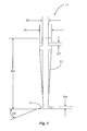
- Fig. 2 is a broken elevation view of blade insert 13 of Fig. 1 in an embodiment of the present invention showing approximate dimensions and various molded features, some of which are important to unique functionality of wiper blades in embodiments of the present invention.
- Fig. 3 is a section view of blade insert 13 taken along section lines 3-3 of Fig. 2 wherein further dimensioning is illustrated.
- a lip region 21 is provided along the longitudinal bottom edge of blade insert 13 with lip elements extending laterally from the bottom edge.
- This lip region may be formed in several different ways in different embodiments of the invention. In a preferred embodiment the lip region is formed at an angle from the blade element as described below in more detail.
- blade insert 13 is molded from a silicon rubber material via injection molding process for similar reasons stated as stated above with respect to the molding of handle sections 17 and 15. It will be apparent to one with skill in the art that blade insert 13 may be molded from other materials known in the art and of suitable flexibility. In this instant embodiment, the inventor prefers silicon rubber with a flexibility rating of approximately 30 to 70 durometer, depending on thickness of the blade. The flexibility of blade insert 13 can be more or less than 30 to 70 durometer, depending on a number of factors that also affect functionality, such as blade thickness, taper, grooving, blade height, and the like.
- a unique and critical function provided by unique characteristics of blade insert 13 is its capability of conforming around sometimes compound and/or radical curves in the body of an automobile, such as in a fender section. It is an object of the present invention is to provide for eliminating standing water in these areas in a safe and efficient manner. This unique capability is made possible in part by the approximate dimensional proportions of blade insert 13 with respect to length and height.
- blade 13 has a height D4 that is a significant fraction of length D1.
- D12 which is the effective height of the blade extending from a handle, is about 21 ⁇ 2 inches. This dimension is the free flexible height from bottom of blade insert 13 to the bottom of the grip handle formed by handle sections 15 and 17 of Fig. 1.
- D1 is about 12 inches.
- the ratio of free height to length in this case is about .21, or about 20 twenty percent. The inventor has discovered empirically that this ratio need to be about ten percent or more for the water blade to be really useful for automobiles with considerable curved surfaces.
- D1 is used in this embodiment both as the length of the handle sections and the wiper blade, as the lengths are substantially the same.
- handle elements and wiper blades will be of different dimensions. It is been found by experiment that in this embodiment, the dimensions 2.5 inches for height D12 and 12 inches for D1, with a thickness of material of approximately 3/16 of an inch produces a useful and preferable result. In other embodiments wherein the overall dimensions of water blade 11 are larger or smaller, a material with a more suitable hardness and perhaps thickness may be employed to aid in achieving desirable flexing properties of water blade 11.
- blade insert 13 Another important characteristic in blade insert 13 is a capability to direct standing water from a surface and to move it in an efficient manner whereby virtually no water residue remains behind on the automobile surface. This directing effect is accomplished by lip 21 which is formed along the longitudinal bottom edge of blade insert 13 and extends in the embodiment shown in the form of a tapered angle on either side. Angled lip 21 produces a rolling action to the water and forces it to ride up on the angled surface of the lip effectively separating the water from the surface of the automobile. It is known to the inventor that some windshield wiper blades incorporate a similar design, and it is well known in the art that this design is effective in removing standing water.
- the angled lip characteristic is unique in conjunction with the height of the blade, in providing a lipped blade with an ability to conform to compound and radical curves in the surface of an automobile.
- a series of molded indentions is provided along the length of blade insert 13.
- the object of these indentions is to minimize the amount of material required to mold blade insert 13. It is known in the art that silicon rubber is relatively expensive when compared to other materials, therefore, considerable savings can be realized by employing such material reducing techniques.
- these indentions are equally spaced approximately 1 ⁇ 2 inch (D13) from center line to center, for 24 indentions.
- the uniform height of these indentions is approximately 17/8 inches (D11), and the dimension from the bottom of the indentions to the bottom of blade insert 13 is approximately 1 ⁇ 2 of an inch (D10).
- a groove 25 is shown running the entire length of blade insert 13.
- Groove 25, described briefly with reference to Fig. 1, is formed around the perimeter of blade insert 13, providing the shape of T-section 18. These grooves provide a secure locking arrangement when handle sections 15 and 17 of Fig. 1 are closed, thereby stopping blade insert 13 from moving up or down with respect to the grip handle.
- the overall thickness of blade insert 13 is approximately 1 ⁇ 2 of an inch (D5).
- a minor thickness of blade insert 13 shown from the inside diameter of T-slot 25 and extending down to the upper shoulder of angled lip 21 is approximately 3/16 of an inch (D6).
- Overall height of blade insert 13 is approximately 2 and 7/8 inches (D4).
- the width of grooves 25 of and the height of angled lip 21 are approximately 1/8 of an inch (D7 and D8 respectively).
- the approximate angle of angled lip 21 in the preferred embodiment shown is 30 degrees (A1). In some embodiments the angle at which lip 21 joins the body of the blade is different, and in some embodiments the lip may be on one side only. The inventor has found that a sharp edge 24 at the end of lip 21 provides a superior wiping action.
- Various dimensions as described herein are approximate only and are meant to illustrate preferred size relationships of features of blade insert 13 in a preferred embodiment of the present invention. It will be apparent to one with skill in the art that many changes can be made with respect to dimensioning water blade 11 without departing from the spirit and scope of the present invention.
- a larger water blade may be used on a larger vehicle such as a semi-trailer rig and so on.
- a water blade with an added height to its blade insert may be used, for example, if a particular type of vehicle contains more curved features that are pronounced.
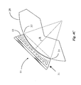
- Figs. 4A-4C illustrate the unique action of water blade 13 in conforming to a curved surface 29. Fig.
- FIG. 4A illustrates a section view of a curved surface, which could be the curvature of a fender, and a water blade 11 including a rigid handle positioned so that lip 21 is just in contact with the curved surface, but flexible blade element 13 is not deformed.
- Fig. 4B is a view in the direction of arrow 27 of Fig. 4A, showing water blade 11 in contact with curved surface with blade element 13 not deformed. In this example, the contact of the blade element with the surface is just a narrow line. This is the situation that will always exist with a blade having little or no height D12 (Fig. 2).
- Fig. 4C is the same section view of a curved surface 29 as shown in Fig. 4a, with water blade 11 in contact with surface 29, and Fig. 4D is a view in the direction of arrow 31.
- blade 11 has been rotated somewhat around the longitudinal axis of the handle, and the blade has been urged toward curved surface 29 in the direction of arrow 33. This movement is applied by a user holding the blade in his or her hand.
- the result of moving the water blade into surface 29 is deformation of blade element 11, bringing the sharp edge of lip region 21 into contact with the surface, and causing flexible blade element 13 to wrap around the curvature of the surface to a significant degree.
- width of the contact area (Fig. 4C) is from point 35 to point 37.
- the significantly wide contact line around the curvature of the surface is a result of the height D12 (Fig. 2) of flexible blade element 13.
- the arc length that may be accomplished by blade element 13 around a curved surface in practicing the present invention is a function of both the height of the blade element and the curvature of the surface.
- the calculations can be complex. A simplified example is given here assuming that the curvature is circular of radius R.
- the overall length of the flexible blade element must be at least equal to the potential length. If the length of the blade element is more than the potential contact length, then part of the blade element will not make contact, as is shown in Fig. 4C. As is described above, in the preferred embodiment shown, the height of the blade element is about 3 inches, and the length is about 12 inches. This relationship has been found by the inventor to be useful for most automobile bodies.
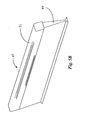
- Fig. 5A is a perspective view of one such alternative embodiment.
- a water blade 39 according to an embodiment of the present invention is molded from material such as silicone material of a single durometer, and a handle portion 41is molded integrally from the same material.
- a lengthwise passage 43 opening to either or both ends is molded into the water blade.
- a rigid stiffener of about the length of the water blade is inserted into the lengthwise passage, and provides rigidity and the function of the rigid handle added according to Fig. 1.
- Fig. 6 is an exploded and broken view of lip 21of water blade insert 13 of Fig. 1 according to an embodiment of the present invention wherein lip 21 is not orthogonal to the height of the blade, but at other than a right angle.
- a windshield wiper blade known to the inventor, have lip regions that are similar in design to lip 21 of Fig. 1, and are known to be effective for removing standing water.
- a windshield wiper is limited by design and rigidity of material in that it is effective for a slightly curved and smooth surface such as a windshield.
- lip 21 combined with the height of blade insert 13 is unique in it's ability to conform to and remove water from compound and radical curves in the surface of an automobile.
- This unique capability of water removal inherent to lip 21, as previously taught, is not limited only to contours and curves such as are common to surfaces of automobiles, trucks and other vehicles, but also extends, in some embodiments, to projections from surfaces as found in rivets, diamond plate, and other ornamental features found on some automobile surfaces, airplane surfaces, truck surfaces, and many other like surfaces that may or may not be associated with a type of vehicle, as is taught below.
- blade insert 13 and lip 21 also play a major roll in the ability of water blade 11 to remove water from more difficult surfaces such as surfaces exhibiting rivet heads, diamond pattern, and so forth.
- blade insert 13 will conform to the contour while the contact side of lip 21 will conform to and around the edges of the diamond pattern effectively removing water.
- Lip 21, for example, may be specially designed with the required length (extension from the body of blade 13) for extending more than the total raised height of an ornamental pattern or an array of rivets and so on.
- a lip such as lip 21, to conform to raised elements in a surface to be wiped, such as rivet heads and diamond patterns mentioned, is the included angle of the lip at the apex of the lip.
- the angle needs to be 30 degrees or less. In some cases the angle needs to be no more than 20 degrees.
- the actual angle that works in some cases is a function also of the length of the lip from the body of the wiper blade, and of the flexibility (softness) of the material of the lip. For a simple lip of substantially triangular shape, an extension from the body of about 3/16 inches, and a durometer of about 30, an angle of from between 10 and 20 degrees is best.
- FIG. 7A is a perspective view of the water blade of Fig. 1 removing (displacing) water from a surface having rivet-head projections according to an embodiment of the present invention.
- a user urges water blade 11 across a surface 61 having projecting rivet heads 63 in the direction of the arrows while, at the same time, keeping a sufficient downward force on surface 61 to cause the lip to conform to the shape of the raised rivet heads.
- the flexible material conforms to the shape of each of the raised regions. In this fashion, water is displaced from all areas exposed to lip 21 including regions in between raised rivet heads of surface 61.
- Fig. 7B is an elevation view of water blade 11 and rivet-studded surface 61 of Fig. 7A.
- Fig. 7A When viewing water blade 11 and surface 61 in the direction of motion as indicated by the directional arrows of Fig. 7A, one can see how tightly lip 21 conforms around raised regions such as those present on surface 61. This unique ability is due to the flexibility of the material and design of lip 21 wherein sufficient length and flexibility is provided for conforming around such shapes.
- one angular side or potion of lip 21 may be formed of a substantially greater length than the opposing side so that dual use is provided to water blade 11 without departing from the spirit and scope of the present invention.
- one side having a longer extension may be used for surfaces having raised regions while the opposing shorter side is used for smooth surfaces and so on.
- alternate designs are provided to the lip section of blade 11 to conform to even more complex surface features as taught below.
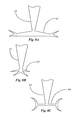
- Fig. 8A is an end view of a lip shape according to another embodiment of the present invention.
- a lip section 65 is formed having a v shape configuration on each opposing end.
- the v form is made to extend along the longitudinal edge of blade insert 13 of Fig. 1. This v formation produces a double-edge effect providing a second swipe at a surface during one initial pass of water blade 11.
- Fig. 8B is an end view of a lip design according to yet another embodiment of the present invention.
- a lip section 67 is formed having a v shape similar to lip 65 of Fig. 8A accept that the opposing formations are much closer together.
- Such a formation may be used, for example, when raised areas or portions of a surface are not particularly high therefore not requiring substantial length with regard to lip formation.
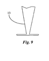
- Fig. 9 is an end view of yet another, and simpler, embodiment of the present invention.
- the lip is a simple straight projection forming an orthogonal T-bar at the bottom of blade 13, the T-bar having essentially constant wall thickness.
- the water wiping apparatus described above in various embodiments provides an effective means for applying spray-on wax or other such finishing products that are sprayed on to a just-washed painted surface. It is an object of the present invention, as shown in the embodiment of Fig. 10A, to provide an improved method and apparatus for evenly spreading spray-on wax or other such vehicle finish products that are sprayed on a wet or dry just-washed painted surface, while significantly improving the application of the distributed spray-on wax or other such spray-on finishing products to the surface. It must be noted, however, that the invention is in no way limited to automotive paint, and the invention may be practiced in various embodiments on a variety of surfaces onto which a spray-on finishing product, such as spray-on wax, may be applied.
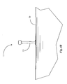
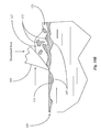
- Fig. 10A is an end view of the lip area of a water blade element according to an embodiment of the present invention, as described in detail above, applied to a painted surface with one lip urged into the surface.
- Blade element 101 similar to that of Fig. 1, is shown in this view having a lip region 103, lip region 103 provided in this embodiment along the longitudinal bottom edge of blade element 101.
- blade element 101 is molded or otherwise formed from a silicon rubber material, but it will be apparent to one skilled in the art however that blade element 101 may be manufactured from other materials having similar suitable flexibility and resilience.
- a surface 105 is illustrated which represents the outer surface of a portion of the body of a vehicle being detailed, which is covered with a layer of typical automotive paint, onto the surface of which an aspect of the present invention, as will be described below in detail, is practiced.
- Surface 105 in the embodiment shown is a typical layering of automotive paint, but may also be of a variety of different paint types applied using various known methods.
- a typical painted surface of a vehicle although appearing substantially smooth and glossy to the naked eye when the paint is properly applied, is actually quite porous, comprising a multitude of tiny pores in the form of valleys and crevices. Such a surface is especially apparent when the painted surface is viewed under very high magnification.
- a plurality of pores 107 indicate such a porous surface in the present illustration, however pores 107 are greatly enlarged in this view, relative to blade element 101 and surface 105, for the purpose of illustration.
- Surface 105 in the embodiment shown is a just-washed painted surface on which a portion of the water used in washing the surface remains. As previously mentioned, however, in practicing the present invention in alternative embodiments it is not required that the just-washed surface of the paint still be wet from the washing. As is typical in the art of detailing an automotive painted finish, the spray-on wax product, or other spray-on finishing product is applied to the wet surface of the paint by spraying just after washing the surface, before the remaining water droplets have evaporated. It is desirable that the spray-on wax or other finishing product sprayed onto the wet surface is mixed with the remaining water droplets on the painted surface, such that dispersion of the wax product is enhanced by virtue of the remaining water.
- Droplets 109 in the embodiment shown represent the remaining water from the washing, mixed with a spray-on wax product that has been sprayed on the wet surface of surface 105.
- solid elements of the spray-on wax product or other finishing product are suspended along with the carrier for the spray-on wax product within the remaining water droplets 109 on surface 105.
- Much greater detail of such suspended wax solids within the remaining water droplets, as well as the tiny crevices and valleys forming the porous painted surface are shown in a subsequent illustration, Fig. 10B.
- lip portion 103 is drawn horizontally as indicated by the directional arrow, across surface 105, with slight downward pressure applied as indicated to lip portion 103, thereby urging the lower tip of lip portion 103 down onto surface 105.
- the wiping action utilized in the present illustration for removing standing water and applying spray-on wax is the same.
- the resulting layer of wax solids which is now evenly distributed across surface 105, even if the wax solution was sprayed on unevenly, remains behind lip portion 103 to form a desired smooth protective and specular wax finish on surface 105 as shown, substantially filling the uneven surface and pores 107 of surface 105.
- the resulting finish appears to be smoother and much shinier to the naked eye when compared to a conventional finish utilizing sets of common wiping cloths or chamois for wiping the water/wax mixture after washing of the surface, as in conventional detailing using spray-on wax products.
- spray-on wax products are solvent-based, instead of water-based, and may contain a much higher proportion of wax solids to carrier solution, and thus provide somewhat more protective abilities to the surface being detailed.
- Many liquid spray wax products are designed just for touch-up waxing of the surface finish of the vehicle without using water at all, the idea being that if the surface to be detailed is substantially free of dirt particles and already has a base wax which has been previously applied, a detailer can spray the dry-wax liquid directly onto the vehicle surface, and utilize the wiper blade of the present invention as described above to evenly disperse the wax solids of the spray-on product over the painted surface.
- blade inserts may be of differing heights and lengths and may be sold separately to be inserted into one handle grip and so forth.
- handle sections 124 and 126 are affixed to one another capturing blade insert 129, utilizing, in one embodiment, a plurality of plastic rivets 133 affixed using a plastic welding technique, rivets 133 strategically located along the length of handle 122 to provide a secure attachment between the two handle sections, while minimizing undue flexing of the assembled handle 122.
- other fabrication methods may be employed such as gluing the handle sections together, utilizing screws or metal rivets, or attaching handle sections together using a plastic welding technique without the use of rivets screws and the like.
- Handle 122 in other alternative embodiment may be molded as a single piece, the blade inserted along a slot at the bottom of the handle, for example. Additionally other materials, plasticized or not, may be used to fabricating handle sections 124 and 126 without departing from the scope and spirit of the invention.
- Water blade 121 is of similar overall form and function to water blade 11 of Fig. 1, with notable differences, however, in the actual shape, size and form of the handle, as well as that of the blade insert, to provide special and optimized functionality.
- Handle 122 in the embodiment illustrated is provided with a rounded upper ridge portion 125 and a rounded lower ridge portion 127, protruding laterally from the side of each of handle sections 124 and 126, and extending substantially along the length of each handle section, thereby forming a valley portion in between the ridges along the length of handle 122. This recessed portion provides for a better grip without it being necessary to partially grip the blade insert.
- Upper ridge portion 125 in a preferred embodiment has a length dimension D14 equal to about 8 3/4 inches, and extends laterally from the side of each handle section approximately twice the distance of that of lower ridge portion 127.
- Lower ridge portion 127 has a length dimension approximately equal to that of handle 122, which is approximately 9 3/4 inches, represented in the illustration by dimension D15.
- the upper and lower ridge portions provide the user with a comfortable and secure grip for water blade 121.
- Upper ridge portion 125 provides the majority of the grasp area for the user's hand, with the user's thumb and fingers preferably resting on and slightly urged into the sides of the handle between the upper and lower ridge portions.
- lower ridge portion 127 in a preferred embodiment protrudes laterally from the sides of handle 122 to an extend that helps prevent the user's thumb or fingers from inadvertently slipping down from the handle onto the blade insert, during use of blade 121, but also is shallow enough wherein the user may also easily extend the thumb or any number of the fingers downward from between the upper and lower ridge portions 125 and 127, while still grasping and using water blade 121, in order to manually press blade insert 129 into recessed areas of a surface to be dried, or shape the blade insert around various odd shapes of protrusions on the surface, for example.
- embodiments of the present invention may have a textured surface over the upper and lower ridge portions, as well as over the flat valley section between the ridges and/or over the surfaces of the rivets 133 or ridges 135 between the upper and lower ridge portions, or may alternatively utilize a succession of raised ribs, bumps, and so on, over the surfaces to further enhance the user's grip.
- Elongated through-openings 131 are provided for water blade 121, located near each opposite and of handle 122, for the purpose of hanging water blade 121 on such as a tool hook, peg, nail, or other similar hanging apparatus, so as to provide convenient storage for water blade 121 while preventing the blade insert from resting on any surface when water blade 121 is not in use, which may over a sustained period of time may possibly deform, or otherwise damage blade insert 121.
- the ends of the handle are now well rounded toward the length direction of the handle and assembles water-wiper blade.
- the purpose of this rounding is to provide for a soft effect in use, such that inadvertent contact with a surface being wiped will be over a broad surface area of the handle, rather than a sharp edge or point. Such contact is discouraged, of course, but in frequent use, nearly certain to happen.
- the rounded "soft" handle helps greatly to avoid marking a finished surface.
- blade insert 129 itself also has a distinct difference in height, shape, and aspect ratios for length to height with respect to the overall dimensions of water blade 121.
- Blade insert 129 is formed similarly to blade insert 13 of Fig. 1, from a silicon rubber material by an injection molding process, and is also similar in flexibility rating, which in alternative embodiments may be more or less than the preferred 30 to 70 durometer, depending on a number of factors that also effect functionality, such as blade thickness, taper, blade height, and so on.
- Blade insert 129 has various dimensions and molded features, several of which are important to unique functionality of wiper blade's in embodiments of the present invention.
- blade insert 129 has a lip region 130 provided along the longitudinal bottom edge of blade insert 129, with lip elements extending laterally from the bottom edge, and also has a groove (not shown) formed around the upper perimeter of blade insert 129 providing a T-section portion enabling a secure locking arrangement when handle sections 124 and 126 are closed, thereby preventing blade insert 129 from moving back and forth with respect to the grip handle.
- blade insert 129 of the present embodiment includes the overall shape of blade insert 129, particularly at the ends, and the length of blade 129 with respect to that of handle portion 122.
- blade insert 13 for water blade 11 of Fig. 1 is rectangular in shape and substantially equal in length to the handle portion, whereas blade insert 129 of the present embodiment is substantially greater in length than the handle portion.
- the length dimension of the lower lip portion of the blade insert which is directly related to the water displacement capability per stroke during use of the water blade having a rectangular blade insert, is equal to the handle length.
- Handle portion 122 of the illustrated embodiment has an overall length of approximately 9 3/4 inches, which is represented in the illustration by dimension D15, whereas blade insert 129 has an overall length at the lower lip portion of approximately 11 inches, represented by dimension D16.
- Each outer edge of blade 129 has a curved portion 132 extending downward beginning at the bottom of each opposite end of handle 122, and curving downward, outward and then downward again thereby providing the increased length at the lower lip portion 130.
- the resulting blade length to handle length ratio of water blade 121 provides a significantly increased water displacement capability per stroke during use, while saving labor and raw materials in the manufacture of the handle, as a handle may be significantly shorter in comparison to the length of lip portion 130, or dimension D16.
- a handle of smaller handle to blade length ratio, such as handle 122 will also be of a significantly lighter weight thereby furthering ease-of-use.
- Downward pressure is evenly distributed along the entire length of lip portion 130 due to the consistency in the resilience, or durometer of the silicon material of blade insert 129 along its length, and the downwardly and outwardly curved outer ends 132 of blade insert 129, which are shaped such that the downward force of the handle during use is applied equally to the center portion and outer tips of lip portion 130, as well as all points in between.
- Fig. 11B is a top view of water blade 121 of Fig. 11A.
- Handle sections 124 and 126 are shown fitted together as previously described forming handle 122, with blade insert 129 captured between handle sections 124 and 126, the outer ends of which are shown continuing out from the furthest outward ends of lower ridge 127.
- Handle sections 124 and 126 each have a downward curvature in the surface beginning where each section meets at the top, such that when fitted together a slightly rounded upper surface is formed in handle 122, which when combined with the curvature of upper ridges of each handle section 124 and 126, a comfortable yet secure grip is provided to the user.
- handle sections 124 and 126 may vary somewhat without departing from the unique aspects of the outer shape of handle 122 formed by sections 124 and 126.
- Blade insert 129 is similar in overall design and functionality to blade 13 of Fig. 1, having a lower lip portion having lip elements extending laterally from the bottom edge, which engage the surface to the dried, and an upper T-portion (partially shown) providing a groove along the length of blade insert 129 for attachment to handle sections 124 and 126.
- Water blade 121 in a preferred embodiment is compact, lightweight and adapted for substantial water displacement capability relative to handle size due to the shape of the wiper blade insert.
- the ability of water blade 121, due to its shorter overall length, to be highly maneuverable over certain contours in surfaces to be dried, while maintaining the excellent water displacement capacity and sufficient downward force for the lip portion of the blade insert, is largely due to the height of the blade relative to the length as illustrated herein.
- blade insert 129 has a height dimension D19 of approximately 1-5/16", which is the effective free flexible height from the bottom of blade insert 129 to the bottom of the grip handle formed by handle sections 124 and 126.
- Length dimension D16 of blade 129 is approximately 11 inches.
- the main body of blade insert 129 has a thickness, represented by dimension D26, of approximately 1/8" to 3/16 inch.
- the ratio of free height to length to thickness of the material of blade insert 129, in this embodiment, is that which has been empirically discovered by the inventor to provide the best combination for usefulness in a smaller, lightweight hand-held water blade such as described herein, when used for dispersing water from, and/or applying products to certain contours and shapes of automotive or other such surfaces.
- Fig. 12A is an elevation view of a hand-held water blade according to yet another alternative embodiment of the present invention.
- Water blade 141 in the embodiment presented has a handle 122 which is somewhat shorter than previous embodiments described, having a dimension D21 which equals approximately 12 inches, and utilizes a rectangular blade insert 149 having the same length dimension as handle 122.
- Blade insert 149 has a higher height to length aspect ratio, providing the user with the ability to displace water from the surface of a particular type of vehicle, for example, which contains many more curved features that are pronounced.
- Handle 142 in this embodiment also comprises a plurality of raised ribs extending lengthwise along each molded handle section, and strategically located around the curved sides of each handle section providing the user with an enhanced grip around an assembled handle 142.
- each handle section comprises raised protrusions having a flat upper surface extending laterally to the length of handle 142, located near either end of the handle sections, and optionally elsewhere as well, such that when the handle sections are fitted together, flat protrusions 145 or formed which enable the user, when not using water blade 141, to rest water blade 141 upside down on a flat, level surface, supported by flat protrusions 145.
- Fig.' 12B is a top view of water blade 141 of Fig. 12A, illustrating the pair of molded handle sections 144 and 146 fitted together according to an embodiment of present invention.
- Handle 142 is formed by attaching handle sections to each other as previously described for other embodiments, having a width dimension D17 equaling approximately 1 3/4 inches, a dimension empirically determined by the inventor to be ideal for the type and shape of handle 142 for providing a most comfortable and secure grip.
- Gripping ribs 147 are shown extending along the length of each handle section providing an enhanced gripping surface for handle 142, and the flat protrusions 145 near each end of handle 142 are clearly visible on the top surface of handle 142.
- Through openings 153 of handle section 144 for accessing mounting brackets (not shown) handle section 146 have slight indentations into the body of handle section 144, which provides the user with a more comfortable grip over the openings and may also enhance the user's grip by allowing the user to anchor finger or thumb while gripping.
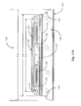
- Fig. 12C is a section view of water blade 141 of Fig. 12B taken along section line 12C-12C of Fig. 12B.
- the curved bell-shape formed by the attached handle sections 144 and 146 can be clearly seen in this view, as can the raised gripping ribs 147 on each handle section, and the flat surface protrusion 145 formed on the top of the handle.
- the handle formed by handle sections 144 and 146 has a height dimension D23 equaling approximately 1 3/8 inches.
- Blade insert 129 has mean material thickness of approximately 1/8 inch, represented by dimension D26, and as mentioned above, has a greater height to length aspect ratio for displacing water from surfaces having many more pronounced curvatures and features, having a height dimension D24 equaling approximately 2 1/4 inches.
- Fig. 13 is an elevation view of a hand-held water blade according to yet another alternative embodiment of the present invention.
- Water blade 161 has a handle 162 comprising a pair of attach handle sections, one of which, handle section 164, is shown in this elevation view.
- Water blade 161 is similar in form and function to water blade 141 of Fig. 12, with the exception that the length of the handle and blade insert are greater with respect to height, than previous embodiments, for the purpose of enabling the user to achieve a much wider contact line on a surface from which water is dispersed during use of water blade 141.
- Water blade 141 is best suited for displacing maximum amounts of water from large surface areas with less pronounced curvature and surface features, in a single stroke.
- Handle 162 has a length dimension D22 of approximately 15 1/2 inches, and has a height dimension D27 of approximately 1 3/4 inches equal to that of handle 142 of Fig. 12, and also has a similar outside shape when the handle sections are attached together, securing blade insert 169. Also, similarly to handle 142 of Fig. 12, a plurality of raised grasping ribs 167 are also provided along the length of handle 122, as well as a plurality of through openings 173 for fastener access, and flat protrusions 165 on the top of handle 162 for standing water blade 161 upside down on a flat surface when water blade 161 is not in use.
- Blade insert 169 attaches to handle 122, and has a lower lip portion 160 similar to embodiments previously described, however, blade insert 169 is substantially greater in length, having a length dimension D23 of approximately 18 inches in this embodiment. At either end of blade insert 169 is a curved portion which extends outwardly from each end of handle 162 and then curves downward to lip portion 160, extending outward from each end of handle 162 to a distance of approximately 1 1/4 inches, represented by dimension D29.
- the resulting blade length to handle length ratio of water blade 161 provides a significantly increased water disbursement capability per stroke during use, and downward pressure from handle 162 is evenly distributed along the entire length of lip portion 130 during use due to the consistency in the resilience, or durometer of the silicon material of blade insert 169 along its length, and the downwardly and outwardly curved outer ends of blade insert 169, which are shaped such that the downward force of the handle during use is applied equally to the center portion and outer tips of lip portion 130, as well as all points in between.
- larger or smaller water blades may be desirable for certain situations.
- larger blades may be provided for use with large vehicles, such as tractor/trailer rigs and the like, or for vans and other trucks.
- interfaces may be provided for handle extensions and the like, to allow a user to present the blade to otherwise hard-to-reach areas.
- Such interfaces might include such as ball and socket joints for flexibility in positioning a water blade in relationship to a handle.
- Fig. 1 shows a two-part handle molded from plastic, the two parts of which may be joined over a set of grooves in a flexible blade portion, and fastened with such as rivets or screws, for example, to provide a relatively rigid handle for the assembled water blade.
- the various handles that have been illustrated and described for a water blade all have been described as having substantial rigidity relative to the separately-molded blade insert.
- handles of substantial softness and flexibility are provided to provide water blades with certain unique characteristics not before apparent.
- the handles are molded in two pieces in a manner that the handle halves may be joined to a blade insert, much in the manner described above.
- the handle material is molded directly onto the blade insert.
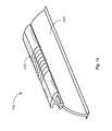
- Fig. 14 is a perspective view of a water wiper blade 1401 in an embodiment of the present invention with a unique handle system 1403 joined to a blade insert 1402.
- Blade insert 1402 is very much like blade insert 129 of Fig. 11A, but handle 1403 differs radically from previous handles and handle systems described above.
- the handle in this embodiment has a substantial tee-shape providing an area under the wings of the handle for a secure grip with the user's fingers, and also in some embodiments has a grooved grip area as shown near the middle of the length of the handle.
- Handle 1403 in one embodiment is a two-part handle system with the parts molded from a soft, rubber-like material, in one embodiment Sanoprene of from about 50 to 70 durometer.
- a more flexible handle rather than the more rigid handles so far described, allows more flexibility for the blade insert, and in many cases improves the facility and efficiency of the wiper in conforming to curvatures of surfaces for removing standing water.
- the softer handle avoids the prospect of damaging a surface, which can in some cases happen if a user were to drop a wiper with a more rigid handle on to, for example, the hood or deck area of an automobile in the process of using the wiper to remove standing water.
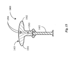
- Fig. 15 is a vertical section view of the wiper of Fig. 14 taken at a right angle to the plane of the blade insert.
- Handle system 1403 in this embodiment is shown as two parts 1501 and 1502.
- handle parts 1501 and 1502 are separately molded, then joined over the grooved top edge 1503 of blade insert 1402.
- a ball-and-socket interface comprising extended ball elements 1504 on one of the two matching parts, mating with substantially spherical sockets on the other part is provided for joining the two parts, such that they may be snapped together.
- Fig. 16 illustrates another embodiment for a soft handle 1602 assembled to a blade insert 1402.
- a special mold is used wherein the blade insert 1402 may be placed in the mold, the mold is closed, and the handle is molded directly onto the blade.
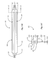
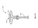
- Fig. 17a illustrates an embodiment wherein a soft handle 1702 is molded directly onto a blade insert 1402, but a plastic stiffener (or spine) 1703 is added to the mold prior to closing the mold and injecting the Sanoprene or similar material. Embedding a stiffener as shown in Fig. 17a provides a very soft outer skin and a more rigid inner spine, so the action of the assembled wiper blade may be controlled while still providing the very soft outer skin.
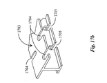
- Fig. 17b illustrates a short section of stiffener 1703, which is made much as a girder is made, but incorporating spaced-apart openings 1704 and 1705.
- the purpose of the opening is two-fold. One purpose is to save the cost of extra plastic material. Another is to assure that the Sanoprene material will adhere well to the stiffener and stay in place during use, as the system undergoes flexing.
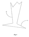
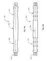
- Fig. 18a illustrates another shape for a soft handle.
- the flexible blade continues to be shown as element 1402, and is shown as such in following examples as well.
- Soft handle 1801 has relatively straight ends 1802 of about equal length, and a narrowed waist section 1803 having grooves 1804 for enhancing a user's grip.
- Fig. 18b illustrates still another shape for a soft handle 1807 wherein the ends 1805 are similar to the ends 1802 of the handle of Fig. 18a, but the center section 1806 is expanded to be of greater girth than the end sections. There are also grip enhancing features 1808.
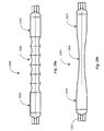
- Fig. 19a illustrates still another handle 1901 having another shape.
- the ends sections 1902 are narrowed and the center section 1903 is of greater girth than the end sections.
- Fig. 19b illustrates an example of a soft handle 1904 having an undulating, repeated feature on each end, shown as sections 1905, and a relatively straight center section.
- Fig. 20a illustrates still another handle 2001 having a shape with undulating features in center section 2003 and relatively straight ends 2002.
- Fig. 20b illustrates still another soft handle 2004 wherein the end sections 2005 are relatively straight and the center section 2006 is narrowed as a waist.
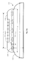
- Figs. 21a and 21b are an elevation view and a section view respectively of a water wiper blade according to a particular embodiment of the present invention.
- wiper blade 2101 has a flexible panel 2103 held in a soft handle 2102.
- Handle 2102 has a central section having scallops as illustrated in Fig. 20a from above.
- Panel 2103 has several oval-shaped openings (five in this example) through which handle material is molded to firmly attach handle 2102 to panel 2103.
- Overall length L3 is about 12.5 inches in one embodiment; height H1 is about 2 inches; height H2 is about .5 inches; length L2 is about 11 inches,; and length L1 is about 8.65 inches in this embodiment.
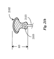
- Fig. 21b illustrates a cross section taken along section line 21b-21b of Fig. 21a. This view shows a distinct pear shape for the soft handle in this embodiment, as well as further detail in the scallops and fastening of the soft handle to the panel.
- the overall height H3 of the soft handle in this embodiment is about 1.4 inches.
Landscapes
- Engineering & Computer Science (AREA)
- Mechanical Engineering (AREA)
- Chemical & Material Sciences (AREA)
- Composite Materials (AREA)
- Vehicle Cleaning, Maintenance, Repair, Refitting, And Outriggers (AREA)
- Cleaning Implements For Floors, Carpets, Furniture, Walls, And The Like (AREA)
- Drying Of Solid Materials (AREA)
- Cleaning In General (AREA)
Applications Claiming Priority (2)
| Application Number | Priority Date | Filing Date | Title |
|---|---|---|---|
| US850471 | 1997-05-05 | ||
| US10/850,471 US7363678B2 (en) | 2002-09-24 | 2004-05-19 | Water wiping apparatus and method for removing standing water from flat and contoured surfaces |
Publications (3)
| Publication Number | Publication Date |
|---|---|
| EP1598248A2 true EP1598248A2 (de) | 2005-11-23 |
| EP1598248A3 EP1598248A3 (de) | 2005-11-30 |
| EP1598248B1 EP1598248B1 (de) | 2008-01-16 |
Family
ID=34925389
Family Applications (1)
| Application Number | Title | Priority Date | Filing Date |
|---|---|---|---|
| EP04014214A Expired - Lifetime EP1598248B1 (de) | 2004-05-19 | 2004-06-17 | Verfahren und Vorrichtung zum Entfernen von stehenden Flüssigkeiten von flachen, gekrümmten gewölbten, oder strukturierten Oberflächen |
Country Status (11)
| Country | Link |
|---|---|
| US (3) | US7363678B2 (de) |
| EP (1) | EP1598248B1 (de) |
| CN (1) | CN1698530A (de) |
| AR (1) | AR049501A1 (de) |
| AT (1) | ATE383980T1 (de) |
| AU (1) | AU2005247311A1 (de) |
| BR (1) | BRPI0501772A (de) |
| CA (1) | CA2472143A1 (de) |
| DE (1) | DE602004011321T2 (de) |
| MX (1) | MXPA05005224A (de) |
| WO (1) | WO2005115213A2 (de) |
Cited By (1)
| Publication number | Priority date | Publication date | Assignee | Title |
|---|---|---|---|---|
| BE1020092A5 (de) * | 2011-07-23 | 2013-04-02 | Jacques Beij | Reinigungsgerât. |
Families Citing this family (51)
| Publication number | Priority date | Publication date | Assignee | Title |
|---|---|---|---|---|
| US7757336B2 (en) * | 2002-09-24 | 2010-07-20 | One Pass Llc | Apparatus for removing standing water from flat and contoured surfaces and textured and patterned surfaces |
| USD538494S1 (en) * | 2003-04-23 | 2007-03-13 | Mps Products, Inc. | Combined squeegee water blade with guard |
| US20060042035A1 (en) * | 2004-08-25 | 2006-03-02 | Te-Ching Liu | Water wiper |
| US7308980B2 (en) * | 2004-11-24 | 2007-12-18 | Martin Engineering Company | Method for distributing a conveyor belt cleaner |
| US20070084931A1 (en) * | 2005-10-18 | 2007-04-19 | Hitoshi Watanabe | Handheld barcode reader |
| US7717524B2 (en) * | 2006-05-19 | 2010-05-18 | Quickie Manufacturing Corporation | Method of molding a cleaning device with a squeegee |
| US20070277340A1 (en) * | 2006-06-01 | 2007-12-06 | Taiwan Washing Brush Co., Ltd. | Water wiper |
| WO2008112959A2 (en) * | 2007-03-14 | 2008-09-18 | Donald Varner | A compound water-wiper and pet hair/ fur removal apparatus and method |
| WO2009023864A1 (en) * | 2007-08-15 | 2009-02-19 | Rebecca Berrigan | Biodegradable shower mat |
| US7946041B2 (en) * | 2007-08-22 | 2011-05-24 | Joseph Frankl | T-back hand saw |
| GB2452705A (en) * | 2007-09-10 | 2009-03-18 | Barry Duke | Skin massaging device |
| CN101902975B (zh) | 2007-10-18 | 2014-06-04 | 尼奥绰德有限公司 | 搏动心脏中瓣膜小叶的微创修复 |
| GB0800770D0 (en) * | 2008-01-17 | 2008-02-27 | Airbus Uk Ltd | Aerofynamic sealing member for aircraft |
| USD607156S1 (en) * | 2008-03-14 | 2009-12-29 | Donald Varner | Body blade |
| US20100064464A1 (en) * | 2008-09-15 | 2010-03-18 | Heidi Beatty | Method of cleaning using a wipe assembly |
| US20100064463A1 (en) * | 2008-09-15 | 2010-03-18 | Heidi Beatty | Wipe assembly |
| USD627530S1 (en) * | 2010-03-11 | 2010-11-16 | 3M Innovative Properties Company | Cleaning tool |
| USD627531S1 (en) * | 2010-03-11 | 2010-11-16 | 3M Innovative Properties Company | Handheld cleaning tool |
| USD706200S1 (en) | 2010-09-22 | 2014-06-03 | Pylon Manufacturing Corporation | Windshield wiper cover |
| DE102011005211B4 (de) * | 2011-03-07 | 2013-12-05 | Karl Göttler | Handreiniger für glatte Flächen |
| US8671498B2 (en) * | 2011-03-17 | 2014-03-18 | Frank J. Ferlito | Cleaning device |
| US9457768B2 (en) | 2011-04-21 | 2016-10-04 | Pylon Manufacturing Corp. | Vortex damping wiper blade |
| US9174609B2 (en) | 2011-04-21 | 2015-11-03 | Pylon Manufacturing Corp. | Wiper blade with cover |
| GB201111168D0 (en) * | 2011-06-30 | 2011-08-17 | Scott Cutters Ltd | Skimming tool |
| US9174611B2 (en) | 2011-07-28 | 2015-11-03 | Pylon Manufacturing Corp. | Windshield wiper adapter, connector and assembly |
| US8806700B2 (en) | 2011-07-29 | 2014-08-19 | Pylon Manufacturing Corporation | Wiper blade connector |
| US9108595B2 (en) | 2011-07-29 | 2015-08-18 | Pylon Manufacturing Corporation | Windshield wiper connector |
| MX347284B (es) | 2011-07-29 | 2017-04-21 | Pylon Mfg Corp | Conector de limpiaparabrisas. |
| US20130219649A1 (en) | 2012-02-24 | 2013-08-29 | Pylon Manufacturing Corp. | Wiper blade |
| MX385411B (es) | 2012-02-24 | 2025-03-18 | Pylon Mfg Corp | Escobilla limpiaparabrisas. |
| US10723322B2 (en) | 2012-02-24 | 2020-07-28 | Pylon Manufacturing Corp. | Wiper blade with cover |
| US10829092B2 (en) | 2012-09-24 | 2020-11-10 | Pylon Manufacturing Corp. | Wiper blade with modular mounting base |
| US10166951B2 (en) | 2013-03-15 | 2019-01-01 | Pylon Manufacturing Corp. | Windshield wiper connector |
| CN103661296A (zh) * | 2013-12-17 | 2014-03-26 | 许世东 | 一种刮水板 |
| US9505380B2 (en) | 2014-03-07 | 2016-11-29 | Pylon Manufacturing Corp. | Windshield wiper connector and assembly |
| USD777079S1 (en) | 2014-10-03 | 2017-01-24 | Pylon Manufacturing Corp. | Wiper blade frame |
| USD787308S1 (en) | 2014-10-03 | 2017-05-23 | Pylon Manufacturing Corp. | Wiper blade package |
| EP3368383B1 (de) | 2015-10-26 | 2021-08-04 | Pylon Manufacturing Corp. | Wischerblatt |
| US10717414B2 (en) | 2016-05-19 | 2020-07-21 | Pylon Manufacturing Corporation | Windshield wiper blade |
| US10766462B2 (en) | 2016-05-19 | 2020-09-08 | Pylon Manufacturing Corporation | Windshield wiper connector |
| US11040705B2 (en) | 2016-05-19 | 2021-06-22 | Pylon Manufacturing Corp. | Windshield wiper connector |
| WO2017201458A1 (en) | 2016-05-19 | 2017-11-23 | Pylon Manufacturing Corp. | Windshield wiper connector |
| AU2017268008A1 (en) | 2016-05-19 | 2018-11-22 | Pylon Manufacturing Corp. | Windshield wiper connector |
| US20190117027A1 (en) * | 2017-10-23 | 2019-04-25 | Hayco Manufacturing Limited | Surface cleaning apparatus |
| USD1010960S1 (en) * | 2019-11-15 | 2024-01-09 | Richard Evans | Interlinking sheath for interchangeable cleaning items |
| CN111021576B (zh) * | 2019-12-14 | 2025-06-27 | 中冶天工集团有限公司 | 一种用于散水的石材及安装方法 |
| CN113243863B (zh) * | 2021-05-27 | 2023-07-21 | 苏州海生新能源科技有限公司 | 一种扫地机器人用旋转刷毛安装座的硬壳及其成型模具 |
| CN113243862B (zh) * | 2021-05-27 | 2023-07-25 | 苏州海生新能源科技有限公司 | 一种扫地机器人用旋转刷毛安装座及其成型模具 |
| CN114468882A (zh) * | 2022-01-25 | 2022-05-13 | 江苏飞慕生物科技有限公司 | 一种具有通水结构的清洗刮条 |
| US20250229201A1 (en) * | 2024-01-11 | 2025-07-17 | Jonathan Zacharias Bror Lindén | Ergonomic Kitchen Sink Cleaning Tool with Debris-Collecting Mesh and Dual-Material Frame |
| US12419481B2 (en) | 2024-01-18 | 2025-09-23 | Timothy D. Bint | Angled auto window washer and squeegee for rear spoilers |
Family Cites Families (27)
| Publication number | Priority date | Publication date | Assignee | Title |
|---|---|---|---|---|
| US1813797A (en) * | 1928-04-27 | 1931-07-07 | Edward S Beach | Method of making rubber-handled tools |
| US1919865A (en) * | 1932-08-27 | 1933-07-25 | Clifford A Schacht | Dish scraper |
| US2052616A (en) * | 1932-12-27 | 1936-09-01 | Ncr Co | Key and method of manufacturing the same |
| US2382304A (en) * | 1941-03-24 | 1945-08-14 | Foltz Carl | Knife and method of manufacture thereof |
| US2319607A (en) * | 1943-01-07 | 1943-05-18 | Joseph D Kevorkian | Knife |
| US3317945A (en) * | 1965-09-17 | 1967-05-09 | Hastings Mfg Co | Molded windshield wiper blade |
| US3676888A (en) * | 1969-10-24 | 1972-07-18 | Vermont American Corp | Adjustable squeegee for applying synthetic fillers |
| US4037285A (en) * | 1976-02-24 | 1977-07-26 | Bela Bottos | Brush for cleaning whitewall tires |
| US4093249A (en) * | 1976-06-28 | 1978-06-06 | Chambers Alan F | Skate assembly |
| US4097951A (en) * | 1977-03-28 | 1978-07-04 | Hurtt Jesse J | Spreader having integrally molded deformable handle and bendable blade |
| US4251086A (en) * | 1979-12-06 | 1981-02-17 | M. O. Sales Ltd. | Ice skate |
| US5141694A (en) * | 1987-04-24 | 1992-08-25 | Warner-Lambert Company | Process for insert molding wet-shaving razor unit |
| US5053178A (en) * | 1987-04-24 | 1991-10-01 | Warner-Lambert Company | Process for insert molding disposable razor |
| US4989511A (en) * | 1989-05-26 | 1991-02-05 | Flexible Products Company | Handle for a squeegee |
| US5349716A (en) * | 1989-10-03 | 1994-09-27 | Robert Hicks Pty Ltd. | Squeegee device including a resiliently flexible blade arrangement |
| DE9104490U1 (de) | 1991-04-12 | 1991-07-18 | Post, Siegfried, 8900 Augsburg | Handwischer mit Schwammkäppchen |
| USD388569S (en) * | 1996-09-24 | 1997-12-30 | Wescon Products Company | Cleaning tool |
| AUPO521297A0 (en) * | 1997-02-19 | 1997-04-11 | E.D. Oates Proprietary Limited | Brush |
| US5920947A (en) * | 1997-05-16 | 1999-07-13 | Goldtime Products, Llc. | Apparatus for removing standing water from flat and contoured surfaces |
| US6516490B1 (en) * | 1999-03-17 | 2003-02-11 | Thomas Hatala | Ice scraper construction |
| USD422124S (en) * | 1999-06-29 | 2000-03-28 | Hanover Catalog Holdings, Inc. | Bath squeegee |
| US6726868B1 (en) * | 2000-03-03 | 2004-04-27 | A. Richard, S.E.N.C. | Double molding process whereby a sign is produced on a product while said product is molded |
| JP2001299649A (ja) | 2000-04-19 | 2001-10-30 | Kuretomu:Kk | 水滴除去具 |
| US20020100135A1 (en) * | 2000-10-31 | 2002-08-01 | Kevin Machesky | Squeegee having at least one tapered end |
| WO2002091896A1 (en) | 2001-05-11 | 2002-11-21 | Killen Raymond H | Cleaning device |
| US20040058074A1 (en) * | 2002-09-24 | 2004-03-25 | Donald Varner | Method and apparatus for removing standing water from, and applying spray-on wax to flat and contoured surfaces and textured and patterned surfaces |
| US6834411B2 (en) * | 2002-12-23 | 2004-12-28 | Kaminstein Imports, Inc. | Shower squeegee |
-
2004
- 2004-05-19 US US10/850,471 patent/US7363678B2/en not_active Expired - Lifetime
- 2004-06-17 EP EP04014214A patent/EP1598248B1/de not_active Expired - Lifetime
- 2004-06-17 DE DE602004011321T patent/DE602004011321T2/de not_active Expired - Lifetime
- 2004-06-17 AT AT04014214T patent/ATE383980T1/de not_active IP Right Cessation
- 2004-06-23 CA CA002472143A patent/CA2472143A1/en not_active Abandoned
- 2004-08-09 CN CNA2004100565484A patent/CN1698530A/zh active Pending
- 2004-12-07 US US11/007,012 patent/US7134163B2/en not_active Expired - Lifetime
-
2005
- 2005-04-20 AU AU2005247311A patent/AU2005247311A1/en not_active Abandoned
- 2005-04-20 WO PCT/US2005/013639 patent/WO2005115213A2/en not_active Ceased
- 2005-05-16 MX MXPA05005224A patent/MXPA05005224A/es not_active Application Discontinuation
- 2005-05-18 AR ARP050102028A patent/AR049501A1/es active IP Right Grant
- 2005-05-19 BR BR0501772-6A patent/BRPI0501772A/pt not_active IP Right Cessation
-
2006
- 2006-06-16 US US11/424,616 patent/US20060220275A1/en not_active Abandoned
Cited By (1)
| Publication number | Priority date | Publication date | Assignee | Title |
|---|---|---|---|---|
| BE1020092A5 (de) * | 2011-07-23 | 2013-04-02 | Jacques Beij | Reinigungsgerât. |
Also Published As
| Publication number | Publication date |
|---|---|
| MXPA05005224A (es) | 2006-01-24 |
| WO2005115213A3 (en) | 2006-09-21 |
| EP1598248B1 (de) | 2008-01-16 |
| CN1698530A (zh) | 2005-11-23 |
| US20060220275A1 (en) | 2006-10-05 |
| DE602004011321T2 (de) | 2009-01-08 |
| AU2005247311A1 (en) | 2005-12-08 |
| BRPI0501772A (pt) | 2006-01-10 |
| DE602004011321D1 (de) | 2008-03-06 |
| US20050150071A1 (en) | 2005-07-14 |
| EP1598248A3 (de) | 2005-11-30 |
| CA2472143A1 (en) | 2005-11-19 |
| US20040211020A1 (en) | 2004-10-28 |
| US7363678B2 (en) | 2008-04-29 |
| AR049501A1 (es) | 2006-08-09 |
| ATE383980T1 (de) | 2008-02-15 |
| US7134163B2 (en) | 2006-11-14 |
| WO2005115213A2 (en) | 2005-12-08 |
Similar Documents
| Publication | Publication Date | Title |
|---|---|---|
| EP1598248B1 (de) | Verfahren und Vorrichtung zum Entfernen von stehenden Flüssigkeiten von flachen, gekrümmten gewölbten, oder strukturierten Oberflächen | |
| US7757336B2 (en) | Apparatus for removing standing water from flat and contoured surfaces and textured and patterned surfaces | |
| US6796000B2 (en) | Method and apparatus for removing standing water from flat and contoured surfaces | |
| US6126756A (en) | Method and apparatus for removing standing water from flat and contoured surfaces and from textured and patterned surfaces | |
| AU745859B2 (en) | Apparatus for removing water from flat, contoured, textured and patterned surfaces | |
| JP2005001664A (ja) | 平坦な表面及び起伏のある表面並びにテクスチャ付きの表面及びパターン付きの表面から静止した水を除去する方法及び装置 | |
| US20050051451A1 (en) | Packaging having access for presenting and displaying special features | |
| WO2001058332A1 (en) | A universal clip-on handle for a water wiper blade | |
| CA2489049A1 (en) | Packaging having access for presenting and displaying special features | |
| HK1024396B (en) | Method and apparatus for removing standing water from flat and contoured surfaces | |
| HK1071043A (en) | Method and apparatus for removing standing water from flat and contoured surfaces | |
| JP2003526408A (ja) | 洗浄器具 |
Legal Events
| Date | Code | Title | Description |
|---|---|---|---|
| PUAI | Public reference made under article 153(3) epc to a published international application that has entered the european phase |
Free format text: ORIGINAL CODE: 0009012 |
|
| PUAL | Search report despatched |
Free format text: ORIGINAL CODE: 0009013 |
|
| AK | Designated contracting states |
Kind code of ref document: A2 Designated state(s): AT BE BG CH CY CZ DE DK EE ES FI FR GB GR HU IE IT LI LU MC NL PL PT RO SE SI SK TR |
|
| AX | Request for extension of the european patent |
Extension state: AL HR LT LV MK |
|
| AK | Designated contracting states |
Kind code of ref document: A3 Designated state(s): AT BE BG CH CY CZ DE DK EE ES FI FR GB GR HU IE IT LI LU MC NL PL PT RO SE SI SK TR |
|
| AX | Request for extension of the european patent |
Extension state: AL HR LT LV MK |
|
| 17P | Request for examination filed |
Effective date: 20060209 |
|
| AKX | Designation fees paid |
Designated state(s): AT BE BG CH CY CZ DE DK EE ES FI FR GB GR HU IE IT LI LU MC NL PL PT RO SE SI SK TR |
|
| GRAP | Despatch of communication of intention to grant a patent |
Free format text: ORIGINAL CODE: EPIDOSNIGR1 |
|
| GRAS | Grant fee paid |
Free format text: ORIGINAL CODE: EPIDOSNIGR3 |
|
| GRAA | (expected) grant |
Free format text: ORIGINAL CODE: 0009210 |
|
| AK | Designated contracting states |
Kind code of ref document: B1 Designated state(s): AT BE BG CH CY CZ DE DK EE ES FI FR GB GR HU IE IT LI LU MC NL PL PT RO SE SI SK TR |
|
| REG | Reference to a national code |
Ref country code: GB Ref legal event code: FG4D |
|
| REG | Reference to a national code |
Ref country code: CH Ref legal event code: EP |
|
| REG | Reference to a national code |
Ref country code: IE Ref legal event code: FG4D |
|
| REF | Corresponds to: |
Ref document number: 602004011321 Country of ref document: DE Date of ref document: 20080306 Kind code of ref document: P |
|
| PG25 | Lapsed in a contracting state [announced via postgrant information from national office to epo] |
Ref country code: NL Free format text: LAPSE BECAUSE OF FAILURE TO SUBMIT A TRANSLATION OF THE DESCRIPTION OR TO PAY THE FEE WITHIN THE PRESCRIBED TIME-LIMIT Effective date: 20080116 |
|
| NLV1 | Nl: lapsed or annulled due to failure to fulfill the requirements of art. 29p and 29m of the patents act | ||
| PG25 | Lapsed in a contracting state [announced via postgrant information from national office to epo] |
Ref country code: CH Free format text: LAPSE BECAUSE OF FAILURE TO SUBMIT A TRANSLATION OF THE DESCRIPTION OR TO PAY THE FEE WITHIN THE PRESCRIBED TIME-LIMIT Effective date: 20080116 Ref country code: LI Free format text: LAPSE BECAUSE OF FAILURE TO SUBMIT A TRANSLATION OF THE DESCRIPTION OR TO PAY THE FEE WITHIN THE PRESCRIBED TIME-LIMIT Effective date: 20080116 Ref country code: FI Free format text: LAPSE BECAUSE OF FAILURE TO SUBMIT A TRANSLATION OF THE DESCRIPTION OR TO PAY THE FEE WITHIN THE PRESCRIBED TIME-LIMIT Effective date: 20080116 Ref country code: ES Free format text: LAPSE BECAUSE OF FAILURE TO SUBMIT A TRANSLATION OF THE DESCRIPTION OR TO PAY THE FEE WITHIN THE PRESCRIBED TIME-LIMIT Effective date: 20080427 |
|
| REG | Reference to a national code |
Ref country code: CH Ref legal event code: PL |
|
| PG25 | Lapsed in a contracting state [announced via postgrant information from national office to epo] |
Ref country code: AT Free format text: LAPSE BECAUSE OF FAILURE TO SUBMIT A TRANSLATION OF THE DESCRIPTION OR TO PAY THE FEE WITHIN THE PRESCRIBED TIME-LIMIT Effective date: 20080116 Ref country code: BG Free format text: LAPSE BECAUSE OF FAILURE TO SUBMIT A TRANSLATION OF THE DESCRIPTION OR TO PAY THE FEE WITHIN THE PRESCRIBED TIME-LIMIT Effective date: 20080416 |
|
| ET | Fr: translation filed | ||
| PG25 | Lapsed in a contracting state [announced via postgrant information from national office to epo] |
Ref country code: PL Free format text: LAPSE BECAUSE OF FAILURE TO SUBMIT A TRANSLATION OF THE DESCRIPTION OR TO PAY THE FEE WITHIN THE PRESCRIBED TIME-LIMIT Effective date: 20080116 Ref country code: BE Free format text: LAPSE BECAUSE OF FAILURE TO SUBMIT A TRANSLATION OF THE DESCRIPTION OR TO PAY THE FEE WITHIN THE PRESCRIBED TIME-LIMIT Effective date: 20080116 Ref country code: SI Free format text: LAPSE BECAUSE OF FAILURE TO SUBMIT A TRANSLATION OF THE DESCRIPTION OR TO PAY THE FEE WITHIN THE PRESCRIBED TIME-LIMIT Effective date: 20080116 Ref country code: PT Free format text: LAPSE BECAUSE OF FAILURE TO SUBMIT A TRANSLATION OF THE DESCRIPTION OR TO PAY THE FEE WITHIN THE PRESCRIBED TIME-LIMIT Effective date: 20080616 |
|
| PG25 | Lapsed in a contracting state [announced via postgrant information from national office to epo] |
Ref country code: CZ Free format text: LAPSE BECAUSE OF FAILURE TO SUBMIT A TRANSLATION OF THE DESCRIPTION OR TO PAY THE FEE WITHIN THE PRESCRIBED TIME-LIMIT Effective date: 20080116 Ref country code: DK Free format text: LAPSE BECAUSE OF FAILURE TO SUBMIT A TRANSLATION OF THE DESCRIPTION OR TO PAY THE FEE WITHIN THE PRESCRIBED TIME-LIMIT Effective date: 20080116 Ref country code: SK Free format text: LAPSE BECAUSE OF FAILURE TO SUBMIT A TRANSLATION OF THE DESCRIPTION OR TO PAY THE FEE WITHIN THE PRESCRIBED TIME-LIMIT Effective date: 20080116 Ref country code: SE Free format text: LAPSE BECAUSE OF FAILURE TO SUBMIT A TRANSLATION OF THE DESCRIPTION OR TO PAY THE FEE WITHIN THE PRESCRIBED TIME-LIMIT Effective date: 20080416 |
|
| PLBE | No opposition filed within time limit |
Free format text: ORIGINAL CODE: 0009261 |
|
| STAA | Information on the status of an ep patent application or granted ep patent |
Free format text: STATUS: NO OPPOSITION FILED WITHIN TIME LIMIT |
|
| PG25 | Lapsed in a contracting state [announced via postgrant information from national office to epo] |
Ref country code: RO Free format text: LAPSE BECAUSE OF FAILURE TO SUBMIT A TRANSLATION OF THE DESCRIPTION OR TO PAY THE FEE WITHIN THE PRESCRIBED TIME-LIMIT Effective date: 20080116 |
|
| 26N | No opposition filed |
Effective date: 20081017 |
|
| PG25 | Lapsed in a contracting state [announced via postgrant information from national office to epo] |
Ref country code: MC Free format text: LAPSE BECAUSE OF NON-PAYMENT OF DUE FEES Effective date: 20080630 |
|
| PG25 | Lapsed in a contracting state [announced via postgrant information from national office to epo] |
Ref country code: EE Free format text: LAPSE BECAUSE OF FAILURE TO SUBMIT A TRANSLATION OF THE DESCRIPTION OR TO PAY THE FEE WITHIN THE PRESCRIBED TIME-LIMIT Effective date: 20080116 |
|
| PG25 | Lapsed in a contracting state [announced via postgrant information from national office to epo] |
Ref country code: CY Free format text: LAPSE BECAUSE OF FAILURE TO SUBMIT A TRANSLATION OF THE DESCRIPTION OR TO PAY THE FEE WITHIN THE PRESCRIBED TIME-LIMIT Effective date: 20080116 |
|
| PGFP | Annual fee paid to national office [announced via postgrant information from national office to epo] |
Ref country code: IE Payment date: 20090618 Year of fee payment: 6 |
|
| PG25 | Lapsed in a contracting state [announced via postgrant information from national office to epo] |
Ref country code: IT Free format text: LAPSE BECAUSE OF FAILURE TO SUBMIT A TRANSLATION OF THE DESCRIPTION OR TO PAY THE FEE WITHIN THE PRESCRIBED TIME-LIMIT Effective date: 20080116 |
|
| PG25 | Lapsed in a contracting state [announced via postgrant information from national office to epo] |
Ref country code: LU Free format text: LAPSE BECAUSE OF NON-PAYMENT OF DUE FEES Effective date: 20080617 Ref country code: HU Free format text: LAPSE BECAUSE OF FAILURE TO SUBMIT A TRANSLATION OF THE DESCRIPTION OR TO PAY THE FEE WITHIN THE PRESCRIBED TIME-LIMIT Effective date: 20080717 |
|
| PG25 | Lapsed in a contracting state [announced via postgrant information from national office to epo] |
Ref country code: TR Free format text: LAPSE BECAUSE OF FAILURE TO SUBMIT A TRANSLATION OF THE DESCRIPTION OR TO PAY THE FEE WITHIN THE PRESCRIBED TIME-LIMIT Effective date: 20080116 |
|
| PG25 | Lapsed in a contracting state [announced via postgrant information from national office to epo] |
Ref country code: GR Free format text: LAPSE BECAUSE OF FAILURE TO SUBMIT A TRANSLATION OF THE DESCRIPTION OR TO PAY THE FEE WITHIN THE PRESCRIBED TIME-LIMIT Effective date: 20080417 |
|
| PGFP | Annual fee paid to national office [announced via postgrant information from national office to epo] |
Ref country code: DE Payment date: 20100824 Year of fee payment: 7 Ref country code: FR Payment date: 20100729 Year of fee payment: 7 |
|
| PG25 | Lapsed in a contracting state [announced via postgrant information from national office to epo] |
Ref country code: IE Free format text: LAPSE BECAUSE OF NON-PAYMENT OF DUE FEES Effective date: 20100617 |
|
| REG | Reference to a national code |
Ref country code: FR Ref legal event code: ST Effective date: 20120229 |
|
| REG | Reference to a national code |
Ref country code: DE Ref legal event code: R119 Ref document number: 602004011321 Country of ref document: DE Effective date: 20120103 |
|
| PG25 | Lapsed in a contracting state [announced via postgrant information from national office to epo] |
Ref country code: FR Free format text: LAPSE BECAUSE OF NON-PAYMENT OF DUE FEES Effective date: 20110630 Ref country code: DE Free format text: LAPSE BECAUSE OF NON-PAYMENT OF DUE FEES Effective date: 20120103 |
|
| PGFP | Annual fee paid to national office [announced via postgrant information from national office to epo] |
Ref country code: GB Payment date: 20200615 Year of fee payment: 17 |
|
| GBPC | Gb: european patent ceased through non-payment of renewal fee |
Effective date: 20210617 |
|
| PG25 | Lapsed in a contracting state [announced via postgrant information from national office to epo] |
Ref country code: GB Free format text: LAPSE BECAUSE OF NON-PAYMENT OF DUE FEES Effective date: 20210617 |