EP1598243B1 - Knieschutz-Airbag und Beinschutzeinrichtung eines Insassen - Google Patents
Knieschutz-Airbag und Beinschutzeinrichtung eines Insassen Download PDFInfo
- Publication number
- EP1598243B1 EP1598243B1 EP05001569A EP05001569A EP1598243B1 EP 1598243 B1 EP1598243 B1 EP 1598243B1 EP 05001569 A EP05001569 A EP 05001569A EP 05001569 A EP05001569 A EP 05001569A EP 1598243 B1 EP1598243 B1 EP 1598243B1
- Authority
- EP
- European Patent Office
- Prior art keywords
- airbag
- knee
- tether
- protecting
- occupant
- Prior art date
- Legal status (The legal status is an assumption and is not a legal conclusion. Google has not performed a legal analysis and makes no representation as to the accuracy of the status listed.)
- Expired - Lifetime
Links
Images

Classifications
-
- B—PERFORMING OPERATIONS; TRANSPORTING
- B60—VEHICLES IN GENERAL
- B60R—VEHICLES, VEHICLE FITTINGS, OR VEHICLE PARTS, NOT OTHERWISE PROVIDED FOR
- B60R21/00—Arrangements or fittings on vehicles for protecting or preventing injuries to occupants or pedestrians in case of accidents or other traffic risks
- B60R21/02—Occupant safety arrangements or fittings, e.g. crash pads
- B60R21/16—Inflatable occupant restraints or confinements designed to inflate upon impact or impending impact, e.g. air bags
- B60R21/23—Inflatable members
- B60R21/231—Inflatable members characterised by their shape, construction or spatial configuration
- B60R21/233—Inflatable members characterised by their shape, construction or spatial configuration comprising a plurality of individual compartments; comprising two or more bag-like members, one within the other
-
- B—PERFORMING OPERATIONS; TRANSPORTING
- B60—VEHICLES IN GENERAL
- B60R—VEHICLES, VEHICLE FITTINGS, OR VEHICLE PARTS, NOT OTHERWISE PROVIDED FOR
- B60R21/00—Arrangements or fittings on vehicles for protecting or preventing injuries to occupants or pedestrians in case of accidents or other traffic risks
- B60R21/02—Occupant safety arrangements or fittings, e.g. crash pads
- B60R21/16—Inflatable occupant restraints or confinements designed to inflate upon impact or impending impact, e.g. air bags
- B60R21/23—Inflatable members
- B60R21/231—Inflatable members characterised by their shape, construction or spatial configuration
- B60R2021/23169—Inflatable members characterised by their shape, construction or spatial configuration specially adapted for knee protection
-
- B—PERFORMING OPERATIONS; TRANSPORTING
- B60—VEHICLES IN GENERAL
- B60R—VEHICLES, VEHICLE FITTINGS, OR VEHICLE PARTS, NOT OTHERWISE PROVIDED FOR
- B60R21/00—Arrangements or fittings on vehicles for protecting or preventing injuries to occupants or pedestrians in case of accidents or other traffic risks
- B60R21/02—Occupant safety arrangements or fittings, e.g. crash pads
- B60R21/16—Inflatable occupant restraints or confinements designed to inflate upon impact or impending impact, e.g. air bags
- B60R21/23—Inflatable members
- B60R21/231—Inflatable members characterised by their shape, construction or spatial configuration
- B60R21/233—Inflatable members characterised by their shape, construction or spatial configuration comprising a plurality of individual compartments; comprising two or more bag-like members, one within the other
- B60R2021/23324—Inner walls crating separate compartments, e.g. communicating with vents
Definitions
- the present invention relates to a knee-protecting airbag and an occupant's-leg-protecting apparatus including this knee-protecting airbag, the knee-protecting airbag serving to prevent the occupant's leg from an impact with the instrument panel in front of the seat and to restrain movement of the knee to restrain forward movement of the lower body of the occupant in an automobile crash.
- Occupant's-leg-protecting apparatuses prevent the occupant's leg from an impact with the instrument panel in front of the seat and being subjected to a heavy load in a frontal crash of a high-speed moving body, such as an automobile.
- Some of the occupant's-leg-protecting apparatuses include a knee-protecting airbag being inflated in front of the occupant's leg, and an inflator (gas generator) for inflating the knee-protecting airbag.
- Japanese Unexamined Patent Application Publication No. 2003-182504 discloses an occupant's-leg-protecting apparatus including a knee-protecting airbag including a tether connecting the cloth on the occupant's side and the cloth on the instrument panel side of the knee-protecting airbag.
- the thickness of the inflated knee-protecting airbag is restricted by this tether.
- the thickness of the knee-protecting airbag be substantially uniform in the lateral direction (from one side to the other side of the knee-protecting airbag).
- the lateral width of the tether be increased and the tether extend continuously in the lateral direction (continuously from one side to the other side of the knee-protecting airbag).
- increasing the lateral width of the tether makes the air-flow space narrow in the knee-protecting airbag and can slow down the inflation rate of the knee-protecting airbag.
- an opening may be provided in the middle in the lateral direction of the tether to form an air-flow space.
- providing such an opening requires time and cost.
- US 2002/0153717 A1 discloses an airbag with a reinforcement region comprising a tether system with tether panels.
- the tether panels are arranged in lapped fashion in the interior of the airbag between a first cloth and a second cloth of the airbag.
- the first cloth of the airbag is arranged on a side of the occupant, while the second cloth is arranged on the opposite side from the occupant.
- the middle of the tethers is narrower than the ends of the tethers, and air-flow spaces are formed between left ends of the tethers and a left side of the airbag and between right ends of the tethers and a right side of the airbag.
- the knee-protecting airbag of the present invention is a knee-protecting airbag being inflated in front of an occupant's leg.
- the airbag includes a first cloth on the side of the occupant; a second cloth on the opposite side from the occupant; and a tether provided in the airbag and connecting the first cloth and the second cloth.
- the tether extends continuously in the lateral direction such that the lateral width of the tether is 55 to 80% of the lateral width of the knee-protecting airbag at a position where the tether connects the first cloth and the second cloth.
- Air-flow spaces are formed between the left end of the tether and the left side of the airbag and between the right end of the tether and the right side of the airbag. In the thickness direction of the airbag, the middle of the tether is narrower than the ends of the tether.
- the occupant's-leg-protecting apparatus of the present invention includes the knee-protecting airbag of the present invention and an inflator for inflating the airbag.
- the term "the tether extends continuously in the lateral direction” means that the lateral width (maximum width) of the tether is 55 to 80% of the lateral width of the knee-protecting airbag (in the position where the tether is fixed).
- the gas flows in the knee-protecting airbag through the air-flow spaces to inflate the airbag, the spaces being formed between the left end of the tether and the left side of the airbag and between the right end of the tether and the right side of the airbag.
- the thickness of the inflated knee-protecting airbag is substantially uniform in the lateral direction.
- the middle of the tether is narrower than the ends of the tether.
- the ends of the tether mean the connecting edges between the tether, the occupant-side cloth of the airbag, and the opposite-side cloth of the airbag. In other words, both lateral edges of the tether are curved inward.
- the knee-protecting airbag of the present invention since both lateral edges of the tether are curved inward, the cross-sectional area of each air-flow space is large. Through these air-flow spaces, the gas can flow in the airbag with a sufficient flow volume and flow rate. Therefore, the knee-protecting airbag is inflated sufficiently rapidly.
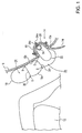
- FIG. 1 is a sectional view of a seat and its vicinity of a vehicle showing an inflated knee-protecting airbag according to an embodiment of the invention.
- FIG. 2(a) is a front view of the inflated knee-protecting airbag in FIG. 1.
- FIG. 2(b) is a sectional view taken along line B-B of FIG. 2(a).
- An occupant's-leg-protecting apparatus 14 of Fig. 1 is installed in an instrument panel 10 in front of a seat 12.
- This occupant's-leg-protecting apparatus 14 includes a retainer 16, which is a container whose front face (occupant side) is open; a knee-protecting airbag 18 of Fig. 1 and Fig. 2 connected to the inside of the retainer 16; an inflator (gas generator) 20 for inflating the knee-protecting airbag 18; and a diffuser 22 disposed in the knee-protecting airbag 18 and guiding the gas flow from the inflator 20 in the lateral direction in the knee-protecting airbag 18.
- a retainer 16 which is a container whose front face (occupant side) is open
- a knee-protecting airbag 18 of Fig. 1 and Fig. 2 connected to the inside of the retainer 16
- an inflator (gas generator) 20 for inflating the knee-protecting airbag 18
- a diffuser 22 disposed in the knee-protecting airbag 18 and guiding the gas flow from the inflator 20 in the lateral direction in the knee-protecting airbag 18.
- the retainer 16 is disposed in an opening 10a provided in the instrument panel 10.
- the knee-protecting airbag 18 and the diffuser 22 are folded and contained in the retainer 16.
- a lid 24 is provided in the front face of the retainer 16 so as to cover the folded knee-protecting airbag 18.
- this lid 24 is disposed so as to be substantially co-planar with the instrument panel 10.
- the opening 10a is provided in the position lower than the top of the seat 12.
- the knee-protecting airbag 18 is inflated upward from the opening 10a along the front face (the occupant side) of the instrument panel 10.
- the knee-protecting airbag 18 includes a uniform width portion 26 and a narrow portion 28.
- the uniform width portion 26 is the upper portion of the airbag 18 and its lateral width is substantially uniform for a predetermined vertical width.
- the narrow portion 28 is the lower portion of the airbag 18 and becomes narrower toward the bottom. The lower end of the narrow portion 28 is connected to the retainer 16.
- the uniform width portion 26 is disposed so as to be higher than the top of the seat 12 when the knee-protecting airbag 18 is inflated from the opening 10a upward along the front face of the instrument panel 10. Therefore, when the knee-protecting airbag 18 is inflated in front of the knees of the occupant, the uniform width portion 26 faces the knees of the occupant sitting in the seat 12.
- the lateral width of the uniform width portion 26 is preferably 500 to 600 mm.
- the lateral width of the front opening of the retainer 16 is preferably less than or equal to half of the width of the uniform width portion 26, more preferably 40 to 50% thereof.
- the left and right sides of the narrow portion 28 preferably connect the lower ends of the left and right sides of the uniform width portion 26 and the left and right lower corners of the front opening of the retainer 16, respectively.
- a plurality of tethers 30 (two tethers 30J and 30K in this embodiment) are provided inside the knee-protecting airbag 18.
- the tethers 30 connect the front side (occupant-side cloth) 18a and the rear side (instrument-panel-side cloth) 18b of the knee-protecting airbag 18.
- the character S denotes seams connecting the tethers 30 (30K and 30J) to the front side 18a and the rear side 18b.
- the upper tether 30J is disposed in a boundary between the uniform width portion 26 and the narrow portion 28 or in a position slightly higher than the boundary (preferably 0 to 70 mm higher than the boundary between the uniform width portion 26 and the narrow portion 28).
- the lower tether 30K is disposed in the middle in the vertical direction of the narrow portion 28.
- the tethers 30 (30J and 30K) extend continuously in the lateral direction. Each tether is connected to the front side 18a and the rear side 18b across a predetermined lateral width. As shown in Fig. 2(b), the left and right ends of each tether 30 (only the tether 30J is shown in Fig. 2(b)) are separated from the left and right sides of the knee-protecting airbag 18, respectively. Between the left end of each tether 30 and the left side of the airbag 18 and between the right end of each tether 30 and the right side of the airbag 18, air-flow spaces V are formed.
- each tether 30 in the thickness direction of the airbag 18, the middle of each tether 30 is narrower than the ends of each tether.
- the ends of each tether mean the stitched edges between each tether, the front side 18a, and the rear side 18b of the airbag. That is to say, in this embodiment, the left edge 30L and the right edge 30R of each tether 30 are curved inward.
- W C is the distance from the line segment connecting the ends of the left edge 30L to the middle of the left edge 30L or the distance from the line segment connecting the ends of the right edge 30R to the middle of the right edge 30R (that is to say, the distance by which the left edge 30L or the right edge 30R is curved inward).
- W E is the width of the left edge 30L or the right edge 30R in the thickness direction of the knee-protecting airbag 18. In the present invention, W C is preferably 5 to 50% of W E .
- each air-flow space V surrounded by the left edge 30L or the right edge 30R of each tether 30 and the left or right side of the knee-protecting airbag 18 is preferably 3000 to 7850 mm 2 , more preferably 4500 to 5500 mm 2 .
- the (shortest) distance from the left edge 30L or the right edge 30R of each tether 30 to the left or right side of the knee-protecting airbag 18 is preferably 80 to 130 mm, more preferably 90 to 120 mm.
- the line segment connecting the left ends of the upper and lower tethers 30J and 30K is preferably parallel to the left side of the narrow portion 28, and the line segment connecting the right ends of the upper and lower tethers 30J and 30K is preferably parallel to the right side of the narrow portion 28.
- the distance between each line segment and the corresponding side of the narrow section 28 is preferably 80 to 130 mm, and more preferably 90 to 120 mm. In the case of such a structure, the gas from the inflator 20 flows rapidly upward through the air-flow spaces V and along the sides of the narrow portion 28.
- the diffuser 22 is provided in the narrow portion 28.
- the inflator 20 is disposed in the diffuser 22.
- the diffuser 22 has a tubular shape and is made by stitching a heat-resistant flexible cloth or synthetic-resin.
- the diffuser 22 is disposed so that openings at the ends face in the lateral direction. Therefore, when the inflator 20 discharges gas in the diffuser 22, the gas from the inflator 20 is guided only in the lateral direction by the openings of the diffuser 22.
- the diffuser 22 has a size capable of projecting forward (toward the occupant) from the front face of the instrument panel 10 as shown in Fig. 1 due to the pressure of the gas discharged from the inflator 20 in the diffuser 22.
- the size of the diffuser 22 is preferably set so that the diffuser 22 projects 60 to 100 mm from the front face of the instrument panel 10, or so that the area of part of each opening corresponding to part of the diffuser 22 projecting from the front face of the instrument panel 10 is 3000 to 7850 mm 2 .
- the inflator 20 is formed in a rod shape, and disposed in the diffuser 22 so that a longitudinal direction thereof is aligned laterally.
- the inflator 20 includes gas-discharging ports (not shown) in its circumferential surface.
- the inflator 20 is held by an inflator holder 34.
- This inflator holder 34 includes a base portion and a band portion fixing the inflator 20 to the base portion (both of the portions are depicted with no reference numeral).
- a stud bolt 34a is projecting from the base portion.
- the stud bolt 34a passes through bolt holes (depicted with no reference numeral) provided in the rear side (opposite side from the occupant) of the diffuser 22 and in the rear side 18b of the lower end of the narrow portion 28, projects from the back (opposite side from the occupant) of the airbag 18, and passes through a bolt hole (depicted with no reference numeral) provided in the retainer 16.
- the inflator 20 discharges gas. Due to the discharge of gas from the inflator 20, the knee-protecting airbag 18 starts to be inflated. The knee-protecting airbag 18 pushes so as to open the lid 24, is inflated on the front of the instrument panel 10, and is inflated upward along the instrument panel 10. Then, the uniform width portion 26 in the upper portion of the inflated knee-protecting airbag 18 faces the knees of the occupant and protects them.
- the narrow portion 28 of the knee-protecting airbag 18 becomes narrower toward the bottom, in other words, becomes wider upward.
- the gas from the inflator 20 disposed in the lower end of the narrow portion 28 flows upward through the air-flow spaces V, which are formed between the left end of each tether 30 (30J, 30K) and the left side of the narrow portion 28 and between the right end of each tether 30 (30J, 30K) and the right side of the narrow portion 28. Therefore, when the knee-protecting airbag 18 is inflated, first, the narrow portion 28 is inflated upward and laterally, next, the uniform width portion 26 is inflated so as to bridge the inflated parts on both sides of the narrow portion 28, and then the middle of the knee-protecting airbag 18 is inflated.
- the cross-sectional area of each air-flow space V is large.
- the cross-sectional area of each of the air-flow spaces V formed between the left edge 30L of each tether 30 and the left side of the airbag 18 and between the right edge 30R of each tether 30 and the right side of the airbag 18 is preferably 3000 to 7850 mm 2 , more preferably 4500 to 5500 mm 2 . Therefore, the gas can flow in the knee-protecting airbag 18 through the air-flow spaces V with sufficient flow volume and flow rate. As a result, the knee-protecting airbag 18 is inflated sufficiently rapidly.
- each tether 30 extends laterally and continuously, the thickness of the inflated knee-protecting airbag 18 is substantially uniform in the lateral direction. Therefore, both knees of the occupant can be protected substantially uniformly by the inflated knee-protecting airbag 18.
- the upper tether 30J is located on the boundary between the uniform width portion 26 and the narrow portion 28 or in the position higher than the boundary, and the tether 30J has a large lateral width. Therefore, the capacity of the uniform width portion 26 is comparatively small, and the uniform width portion 26 is inflated rapidly.
- both sides and the uniform width portion 26 of the knee-protecting airbag 18 are inflated rapidly, the knee-protecting airbag 18 are inflated rapidly laterally and upward.
- the diffuser 22 guides the gas flow from the inflator 20 to the lateral direction, the lateral inflation of the knee-protecting airbag 18 is more rapid.
- the diffuser 22 in the knee-protecting airbag 18 projects 60 to 100 mm forward from the front face of the instrument panel 10 due to the pressure of the gas discharged from the inflator 20. Therefore, the gas from the inflator 20 flows from the openings of the diffuser 22 in the lateral direction without hitting the inner wall of the knee-protecting airbag 18 and changing direction. As a result, the gas from the inflator 20 can be guided efficiently in the lateral direction.
Landscapes
- Engineering & Computer Science (AREA)
- Mechanical Engineering (AREA)
- Air Bags (AREA)
Claims (4)
- Knieschutzairbag (18), welcher vor einem Insassenbein aufgeblasen wird, wobei der Airbag umfasst:einen ersten Stoff (18a) auf der Seite des Insassen;einen zweiten Stoff (18b) an der gegenüberliegenden Seite des Insassens; undeinen Haltegurt (30), welcher in dem Airbag vorgesehen ist und den ersten Stoff (18a) und den zweiten Stoff (18b) verbindet,wobei sich der Haltegurt (30) in der seitlichen Richtung derart erstreckt, dass die seitliche Breite des Haltegurts (30) 55 bis 80% der seitlichen Breite des Knieschutzairbags (18) an einer Position beträgt, wo der Haltegurt (30) den ersten Stoff (18a) und den zweiten Stoff (18b) verbindet;
wobei Luftströmungsräume (V) zwischen dem linken Ende des Haltegurts (30L) und der linken Seite des Airbags und zwischen dem rechten Ende des Haltegurts (30R) und der rechten Seite des Airbags ausgebildet sind; und
wobei in der Dickenrichtung des Airbags die Mitte des Haltegurts (30) schmaler als die Enden des Haltegurts (30) ist. - Knieschutzairbag (18) nach Anspruch 1,
wobei ein Diffusor (22) das Gas, welches von einer Aufblasvorrichtung (20) eingeführt wird, in der seitlichen Richtung führt. - Knieschutzairbag (18) nach Anspruch 2,
wobei der Diffusor (22) in dem Airbag (18) derart angeordnet ist, dass Öffnungen davon in der seitlichen Richtung derart gegenüberliegend sind, dass das Gas von der Aufblasvorrichtung (20) durch die Öffnungen nur in der seitlichen Richtung geführt wird. - Insassenbeinschutzvorrichtung (14) umfassend:einen Knieschutzairbag, welcher geeignet ist, vor einem Insassenbein aufgeblasen zu werden; undeine Aufblasvorrichtung zum Aufblasen des Airbags,wobei der Airbag der Knieschutzairbag (18) nach einem der Ansprüche 1-3 ist.
Applications Claiming Priority (2)
| Application Number | Priority Date | Filing Date | Title |
|---|---|---|---|
| JP2004054306 | 2004-02-27 | ||
| JP2004054306A JP4534525B2 (ja) | 2004-02-27 | 2004-02-27 | ニーバッグ及び乗員脚部保護装置 |
Publications (2)
| Publication Number | Publication Date |
|---|---|
| EP1598243A1 EP1598243A1 (de) | 2005-11-23 |
| EP1598243B1 true EP1598243B1 (de) | 2007-08-08 |
Family
ID=34879738
Family Applications (1)
| Application Number | Title | Priority Date | Filing Date |
|---|---|---|---|
| EP05001569A Expired - Lifetime EP1598243B1 (de) | 2004-02-27 | 2005-01-26 | Knieschutz-Airbag und Beinschutzeinrichtung eines Insassen |
Country Status (5)
| Country | Link |
|---|---|
| US (2) | US7380823B2 (de) |
| EP (1) | EP1598243B1 (de) |
| JP (1) | JP4534525B2 (de) |
| CN (1) | CN100469621C (de) |
| DE (1) | DE602005001888T2 (de) |
Families Citing this family (34)
| Publication number | Priority date | Publication date | Assignee | Title |
|---|---|---|---|---|
| JP4345645B2 (ja) * | 2004-11-09 | 2009-10-14 | 豊田合成株式会社 | 膝保護用エアバッグ装置 |
| JP5219060B2 (ja) * | 2005-11-02 | 2013-06-26 | タカタ株式会社 | エアバッグ装置 |
| EP1800941B1 (de) * | 2005-12-01 | 2010-06-09 | Toyoda Gosei Co., Ltd. | Passagierschutzvorrichtung |
| US7942440B2 (en) * | 2005-12-22 | 2011-05-17 | Autoliv Asp, Inc. | Channel and diffuser airbag |
| KR100757626B1 (ko) * | 2006-06-23 | 2007-09-10 | 현대모비스 주식회사 | 에어백 장치의 쿠션 |
| US20080116669A1 (en) * | 2006-11-14 | 2008-05-22 | Toyoda Gosei Co., Ltd. | Knee-protecting airbag device |
| JP2008137406A (ja) * | 2006-11-30 | 2008-06-19 | Toyoda Gosei Co Ltd | 車両の乗員保護装置 |
| WO2009029203A1 (en) * | 2007-08-27 | 2009-03-05 | Key Safety Systems, Inc. | Knee airbag module |
| US8096578B2 (en) | 2007-11-02 | 2012-01-17 | Tk Holdings Inc. | Knee airbag |
| JP4591574B2 (ja) * | 2008-08-06 | 2010-12-01 | トヨタ自動車株式会社 | 車両用ニーエアバッグ装置 |
| JP4433078B2 (ja) * | 2008-08-26 | 2010-03-17 | トヨタ自動車株式会社 | 車両用ニーエアバッグ装置 |
| US20100270782A1 (en) * | 2009-04-27 | 2010-10-28 | Autoliv Asp, Inc. | Inflatable knee airbag assemblies with bag straps for wrapping the airbags and optimizing deployment |
| US8777262B2 (en) | 2009-04-27 | 2014-07-15 | Autoliv Asp, Inc. | Airbag assemblies with stabilizer straps |
| US8500157B2 (en) | 2009-04-27 | 2013-08-06 | Autoliv Asp, Inc. | Knee airbag assemblies and related methods |
| US8118325B2 (en) * | 2009-04-27 | 2012-02-21 | Autoliv Asp, Inc. | Inflatable knee airbags and internal tethers produced from single panels of material |
| US8083254B2 (en) * | 2009-04-27 | 2011-12-27 | Autoliv Asp, Inc. | Knee airbag assemblies configured for inflator insertion and inflator-mediated coupling to an airbag housing |
| US8297649B2 (en) * | 2009-07-16 | 2012-10-30 | Autoliv Asp, Inc. | Inflatable knee airbag having two chambers separated by an internal tether |
| US8272667B2 (en) * | 2009-11-03 | 2012-09-25 | Autoliv Asp, Inc. | Low-mount inflatable knee airbags having serial chambers |
| CN105584453B (zh) | 2009-11-10 | 2018-11-16 | 丰田合成株式会社 | 卷绕气囊装置 |
| US8500155B2 (en) * | 2009-12-22 | 2013-08-06 | Autoliv Asp, Inc. | Inflatable airbag assembly with an integral cover |
| JP5560321B2 (ja) * | 2010-02-17 | 2014-07-23 | オートリブ ディベロップメント エービー | ニーエアバッグ |
| JP5561001B2 (ja) * | 2010-07-30 | 2014-07-30 | 豊田合成株式会社 | エアバッグ装置 |
| US8360464B2 (en) | 2010-08-31 | 2013-01-29 | Autoliv Asp, Inc. | Covers for inflatable knee airbag housings |
| US8297650B2 (en) | 2010-08-31 | 2012-10-30 | Autoliv Asp, Inc. | Inflatable knee airbag assemblies with articulating housings |
| US8696019B2 (en) * | 2011-03-21 | 2014-04-15 | Tk Holdings Inc. | Knee airbag module |
| US8590928B2 (en) | 2011-07-18 | 2013-11-26 | Ford Global Technologies, Llc | Knee airbag with passive venting for out of position occupant protection |
| WO2013054397A1 (ja) * | 2011-10-11 | 2013-04-18 | トヨタ自動車株式会社 | 車両用ニーエアバッグ装置 |
| US8540276B2 (en) | 2011-11-07 | 2013-09-24 | Autoliv Asp, Inc. | Inflatable knee airbag assemblies with cushion fold pattern |
| US8505963B1 (en) | 2012-02-24 | 2013-08-13 | Autoliv Asp, Inc. | Airbag assemblies with strap clamps |
| US8814201B2 (en) * | 2012-08-17 | 2014-08-26 | Chrysler Group Llc | Knee airbag having increased package width |
| US9010804B2 (en) | 2013-03-15 | 2015-04-21 | Autoliv Asp, Inc. | Airbag assemblies with constrained stabilizer straps |
| KR101614491B1 (ko) * | 2013-04-03 | 2016-04-25 | 아우토리브 디벨롭먼트 아베 | 무릎 에어백 장치의 에어백 |
| JP6287225B2 (ja) | 2014-01-10 | 2018-03-07 | タカタ株式会社 | 脚部用エアバッグ装置及び自動車 |
| US10696266B2 (en) | 2017-11-10 | 2020-06-30 | Autoliv Asp, Inc. | Inflatable knee airbag assemblies |
Family Cites Families (19)
| Publication number | Priority date | Publication date | Assignee | Title |
|---|---|---|---|---|
| JP2572688Y2 (ja) * | 1992-09-03 | 1998-05-25 | 株式会社東海理化電機製作所 | エアバッグ装置の袋体 |
| JP2914423B2 (ja) * | 1994-06-20 | 1999-06-28 | 池田物産株式会社 | エアバッグ装置のエアバッグ本体 |
| US6113141A (en) * | 1998-07-06 | 2000-09-05 | American Components, Inc. | Roll-over air bag |
| US6217059B1 (en) * | 1999-08-16 | 2001-04-17 | Trw Inc. | Apparatus for helping to protect a vehicle occupant's legs |
| JP4608072B2 (ja) * | 2000-02-25 | 2011-01-05 | タカタ株式会社 | エアバッグ装置 |
| US6783155B2 (en) * | 2000-04-14 | 2004-08-31 | Milliken & Company | Air bag tether construction |
| US6315324B1 (en) * | 2000-04-14 | 2001-11-13 | Milliken & Company | Air bag tether construction |
| US6450529B1 (en) * | 2000-06-23 | 2002-09-17 | Breed Automotive Technologies, Inc. | Inflatable side air bag curtain module with chamber separators |
| US6945557B2 (en) * | 2001-11-09 | 2005-09-20 | Toyoda Gosei Co., Ltd. | Knee protecting airbag device |
| JP3912144B2 (ja) * | 2001-05-21 | 2007-05-09 | タカタ株式会社 | 助手席用乗員脚部保護装置 |
| JP3772742B2 (ja) * | 2001-12-25 | 2006-05-10 | 豊田合成株式会社 | 膝保護用エアバッグ装置 |
| DE10141437A1 (de) * | 2001-08-23 | 2003-02-20 | Breed Automotive Tech | Luftsack und Verfahren zum Herstellen eines Luftsackes |
| US7055858B2 (en) * | 2002-04-01 | 2006-06-06 | Toyoda Gosei Co., Ltd. | Airbag device |
| JP3948332B2 (ja) * | 2002-04-15 | 2007-07-25 | タカタ株式会社 | 乗員脚部保護装置 |
| JP3900008B2 (ja) * | 2002-05-22 | 2007-04-04 | 豊田合成株式会社 | エアバッグ |
| JP4063168B2 (ja) * | 2003-07-11 | 2008-03-19 | 豊田合成株式会社 | 膝保護用エアバッグ |
| JP2005029101A (ja) * | 2003-07-11 | 2005-02-03 | Toyoda Gosei Co Ltd | 膝保護用エアバッグ |
| KR100547173B1 (ko) * | 2003-10-17 | 2006-01-31 | 현대모비스 주식회사 | 에어백 장치의 쿠션 |
| US7066487B2 (en) * | 2003-11-11 | 2006-06-27 | Ford Global Technologies, Llc | Airbag with internal positioning panels for sequential deployment |
-
2004
- 2004-02-27 JP JP2004054306A patent/JP4534525B2/ja not_active Expired - Fee Related
-
2005
- 2005-01-26 DE DE602005001888T patent/DE602005001888T2/de not_active Expired - Lifetime
- 2005-01-26 EP EP05001569A patent/EP1598243B1/de not_active Expired - Lifetime
- 2005-02-24 US US11/063,875 patent/US7380823B2/en not_active Expired - Lifetime
- 2005-02-25 CN CNB2005100517201A patent/CN100469621C/zh not_active Expired - Fee Related
-
2008
- 2008-03-03 US US12/073,191 patent/US7669895B2/en not_active Expired - Fee Related
Non-Patent Citations (1)
| Title |
|---|
| None * |
Also Published As
| Publication number | Publication date |
|---|---|
| US7669895B2 (en) | 2010-03-02 |
| EP1598243A1 (de) | 2005-11-23 |
| DE602005001888D1 (de) | 2007-09-20 |
| US20050189741A1 (en) | 2005-09-01 |
| JP4534525B2 (ja) | 2010-09-01 |
| JP2005239054A (ja) | 2005-09-08 |
| US20080157509A1 (en) | 2008-07-03 |
| CN100469621C (zh) | 2009-03-18 |
| US7380823B2 (en) | 2008-06-03 |
| DE602005001888T2 (de) | 2008-04-30 |
| CN1660629A (zh) | 2005-08-31 |
Similar Documents
| Publication | Publication Date | Title |
|---|---|---|
| EP1598243B1 (de) | Knieschutz-Airbag und Beinschutzeinrichtung eines Insassen | |
| US7458605B2 (en) | Airbag, airbag system and vehicle | |
| CN1629014B (zh) | 膝部气袋和乘员腿部保护装置 | |
| US7264269B2 (en) | Head-protecting airbag and head-protecting airbag device | |
| EP1832475B1 (de) | Seitenairbagvorrichtung für fahrzeug | |
| US7267366B2 (en) | Airbag, airbag device and vehicle | |
| US6971664B2 (en) | Passenger-side airbag apparatus | |
| US7648158B2 (en) | Twin airbag | |
| JP2001171471A (ja) | 膨張可能エアバッグ | |
| US7946619B2 (en) | Airbag | |
| EP1630044B1 (de) | Gassack und Gassacksystem | |
| JP4553577B2 (ja) | ニーバッグ及び乗員脚部保護装置 | |
| EP1905658B1 (de) | Insassenrückhaltevorrichtung | |
| CN112124244B (zh) | 车辆用膝部安全气囊装置 | |
| JP2010215096A (ja) | 頭部保護エアバッグ装置 | |
| JP2009023493A (ja) | エアバッグ装置 | |
| KR20220104401A (ko) | 사이드 에어백 | |
| JP2007055608A (ja) | 乗員脚部保護装置 | |
| JP2010006374A (ja) | ニーバッグ及び乗員脚部保護装置 | |
| JP2003034210A (ja) | 頭部保護エアバッグ装置 |
Legal Events
| Date | Code | Title | Description |
|---|---|---|---|
| PUAI | Public reference made under article 153(3) epc to a published international application that has entered the european phase |
Free format text: ORIGINAL CODE: 0009012 |
|
| AK | Designated contracting states |
Kind code of ref document: A1 Designated state(s): AT BE BG CH CY CZ DE DK EE ES FI FR GB GR HU IE IS IT LI LT LU MC NL PL PT RO SE SI SK TR |
|
| AX | Request for extension of the european patent |
Extension state: AL BA HR LV MK YU |
|
| 17P | Request for examination filed |
Effective date: 20060329 |
|
| AKX | Designation fees paid |
Designated state(s): DE FR GB SE |
|
| 17Q | First examination report despatched |
Effective date: 20060705 |
|
| GRAP | Despatch of communication of intention to grant a patent |
Free format text: ORIGINAL CODE: EPIDOSNIGR1 |
|
| GRAS | Grant fee paid |
Free format text: ORIGINAL CODE: EPIDOSNIGR3 |
|
| GRAA | (expected) grant |
Free format text: ORIGINAL CODE: 0009210 |
|
| AK | Designated contracting states |
Kind code of ref document: B1 Designated state(s): DE FR GB SE |
|
| REG | Reference to a national code |
Ref country code: GB Ref legal event code: FG4D |
|
| REF | Corresponds to: |
Ref document number: 602005001888 Country of ref document: DE Date of ref document: 20070920 Kind code of ref document: P |
|
| ET | Fr: translation filed | ||
| REG | Reference to a national code |
Ref country code: SE Ref legal event code: TRGR |
|
| PGFP | Annual fee paid to national office [announced via postgrant information from national office to epo] |
Ref country code: SE Payment date: 20080104 Year of fee payment: 4 |
|
| PLBE | No opposition filed within time limit |
Free format text: ORIGINAL CODE: 0009261 |
|
| STAA | Information on the status of an ep patent application or granted ep patent |
Free format text: STATUS: NO OPPOSITION FILED WITHIN TIME LIMIT |
|
| 26N | No opposition filed |
Effective date: 20080509 |
|
| EUG | Se: european patent has lapsed | ||
| PG25 | Lapsed in a contracting state [announced via postgrant information from national office to epo] |
Ref country code: SE Free format text: LAPSE BECAUSE OF NON-PAYMENT OF DUE FEES Effective date: 20090127 |
|
| PGFP | Annual fee paid to national office [announced via postgrant information from national office to epo] |
Ref country code: FR Payment date: 20140108 Year of fee payment: 10 |
|
| PGFP | Annual fee paid to national office [announced via postgrant information from national office to epo] |
Ref country code: GB Payment date: 20140122 Year of fee payment: 10 |
|
| GBPC | Gb: european patent ceased through non-payment of renewal fee |
Effective date: 20150126 |
|
| PG25 | Lapsed in a contracting state [announced via postgrant information from national office to epo] |
Ref country code: GB Free format text: LAPSE BECAUSE OF NON-PAYMENT OF DUE FEES Effective date: 20150126 |
|
| REG | Reference to a national code |
Ref country code: FR Ref legal event code: ST Effective date: 20150930 |
|
| PG25 | Lapsed in a contracting state [announced via postgrant information from national office to epo] |
Ref country code: FR Free format text: LAPSE BECAUSE OF NON-PAYMENT OF DUE FEES Effective date: 20150202 |
|
| REG | Reference to a national code |
Ref country code: DE Ref legal event code: R082 Ref document number: 602005001888 Country of ref document: DE Representative=s name: KRAUS & WEISERT PATENTANWAELTE PARTGMBB, DE Ref country code: DE Ref legal event code: R081 Ref document number: 602005001888 Country of ref document: DE Owner name: JOYSON SAFETY SYSTEMS JAPAN K.K., JP Free format text: FORMER OWNER: TAKATA CORP., TOKIO/TOKYO, JP |
|
| PGFP | Annual fee paid to national office [announced via postgrant information from national office to epo] |
Ref country code: DE Payment date: 20210120 Year of fee payment: 17 |
|
| REG | Reference to a national code |
Ref country code: DE Ref legal event code: R119 Ref document number: 602005001888 Country of ref document: DE |
|
| PG25 | Lapsed in a contracting state [announced via postgrant information from national office to epo] |
Ref country code: DE Free format text: LAPSE BECAUSE OF NON-PAYMENT OF DUE FEES Effective date: 20220802 |