EP1598237B1 - Vehicle exterior mirror - Google Patents
Vehicle exterior mirror Download PDFInfo
- Publication number
- EP1598237B1 EP1598237B1 EP05010416A EP05010416A EP1598237B1 EP 1598237 B1 EP1598237 B1 EP 1598237B1 EP 05010416 A EP05010416 A EP 05010416A EP 05010416 A EP05010416 A EP 05010416A EP 1598237 B1 EP1598237 B1 EP 1598237B1
- Authority
- EP
- European Patent Office
- Prior art keywords
- mirror
- frame
- mirror according
- light
- illuminant
- Prior art date
- Legal status (The legal status is an assumption and is not a legal conclusion. Google has not performed a legal analysis and makes no representation as to the accuracy of the status listed.)
- Expired - Fee Related
Links
Images

Classifications
-
- B—PERFORMING OPERATIONS; TRANSPORTING
- B60—VEHICLES IN GENERAL
- B60R—VEHICLES, VEHICLE FITTINGS, OR VEHICLE PARTS, NOT OTHERWISE PROVIDED FOR
- B60R1/00—Optical viewing arrangements; Real-time viewing arrangements for drivers or passengers using optical image capturing systems, e.g. cameras or video systems specially adapted for use in or on vehicles
- B60R1/12—Mirror assemblies combined with other articles, e.g. clocks
- B60R1/1207—Mirror assemblies combined with other articles, e.g. clocks with lamps; with turn indicators
-
- B—PERFORMING OPERATIONS; TRANSPORTING
- B60—VEHICLES IN GENERAL
- B60Q—ARRANGEMENT OF SIGNALLING OR LIGHTING DEVICES, THE MOUNTING OR SUPPORTING THEREOF OR CIRCUITS THEREFOR, FOR VEHICLES IN GENERAL
- B60Q1/00—Arrangement of optical signalling or lighting devices, the mounting or supporting thereof or circuits therefor
- B60Q1/26—Arrangement of optical signalling or lighting devices, the mounting or supporting thereof or circuits therefor the devices being primarily intended to indicate the vehicle, or parts thereof, or to give signals, to other traffic
- B60Q1/2661—Arrangement of optical signalling or lighting devices, the mounting or supporting thereof or circuits therefor the devices being primarily intended to indicate the vehicle, or parts thereof, or to give signals, to other traffic mounted on parts having other functions
- B60Q1/2665—Arrangement of optical signalling or lighting devices, the mounting or supporting thereof or circuits therefor the devices being primarily intended to indicate the vehicle, or parts thereof, or to give signals, to other traffic mounted on parts having other functions on rear-view mirrors
Description
Die Erfindung betrifft einen Außenrückblickspiegel für Fahrzeuge, insbesondere Kraftfahrzeuge, nach dem Oberbegriff des Anspruches 1.The invention relates to an exterior rearview mirror for vehicles, in particular motor vehicles, according to the preamble of
Es ist bekannt, am Außenrückblickspiegel Signal-, Umfeld- oder Anzeigeleuchten vorzusehen. Sie sind entweder im Spiegelgehäuse oder im Spiegelfuß vorgesehen.It is known to provide on the exterior rearview mirror signal, environment or indicator lights. They are provided either in the mirror housing or in the mirror base.
Beim gattungsgemäßen Außenrückblickspiegel (
Bei einem anderen bekannten Außenrückblickspiegel (
Bei einem anderen bekannten Außenrückblickspiegel (
Aus der
Bei einem weiteren bekannten Außenrückblickspiegel (
Es ist schließlich ein Außenrückblickspiegel bekannt (
Der Erfindung liegt die Aufgabe zugrunde, den gattungsgemäßen Außenrückblickspiegel so auszubilden, dass eine einfache und günstige Montage - eines Leuchtmittels bei geringem Platzbedarf möglich ist.The invention has the object of providing the generic exterior rearview mirror in such a way that a simple and inexpensive installation - a light source is possible in a small footprint.
Diese Aufgabe wird beim gattungsgemäßen Rückblickspiegel erfindungsgemäß mit den kennzeichnenden Merkmalen des Anspruches 1 gelöst.This object is achieved in the generic rearview mirror according to the invention with the characterizing features of
Beim erfindungsgemäßen Außenrückblickspiegel ist das Leuchtmittel im Rahmen unlösbar befestigt. Es kann einfach und platzsparend im Rahmen untergebracht und dort sicher gehalten werden. Die vom Leuchtmittel ausgesandten Strahlen gelangen durch den Lichtaustritt, der sich neben dem Spiegelglas im Rahmen befindet, nach außen. Der Lichtaustritt ist so angeordnet, dass das austretende Licht etwa parallel zum Spiegelglas strahlt.In the exterior rearview mirror according to the invention, the lighting means is fixed inseparably in the frame. It can be easily and space-saving housed in the frame and kept safe there. The rays emitted by the lamp pass through the light exit, which is located next to the mirror glass in the frame to the outside. The light exit is arranged so that the exiting light radiates approximately parallel to the mirror glass.
Weitere Merkmale der Erfindung ergeben sich aus den weiteren Ansprüchen, der Beschreibung und den Zeichnungen.Further features of the invention will become apparent from the other claims, the description and the drawings.
Die Erfindung wird nachstehend anhand mehrerer in den Zeichnungen dargestellter Ausführungsbeispiele näher beschrieben. Es zeigt:
- Fig. 1
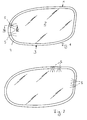
- in Ansicht einen erfindungsgemäßen Außenrückblickspiegel mit einem Spiegelglas, das von einem Rahmen umgeben ist, in dem Einbauleuchten vorgesehen sind,
- Fig. 2
- eine weitere Ausführungsform eines erfindungsgemäßen Außenrückblickspiegels in einer Darstellung entsprechend
Fig. 1 , - Fig. 3
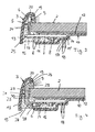
- in vergrößerter Darstellung einen Schnitt längs der Linie III-III in
Fig. 1 durch eine Einbauleuchte des Rahmens, - Fig. 4
- eine Darstellung entsprechend
Fig. 3 , jedoch mit einer anders ausgebildeten Einbauleuchte, - Fig. 5 und Fig. 3b
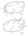
- jeweils einen weiteren erfindungsgemäßen Außenrückblickspiegel in einer Darstellung entsprechend
Fig. 1 , - Fig. 7
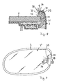
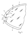
- einen weiteren nicht erfindungsgemäßen Außenspiegel
- Fig. 8
- einen Schnitt längs der Linie XIII-XIII in
Fig. 7 , - Fig. 9
- einen Teil eines weiteren erfindungsgemäßen Außenrückblickspiegels in einer Darstellung entsprechend
Fig. 1 , - Fig. 10
- einen Schnitt längs der Linie X-X in
Fig. 9 .
- Fig. 1
- in view an exterior rearview mirror according to the invention with a mirror glass, which is surrounded by a frame in which recessed lights are provided,
- Fig. 2
- a further embodiment of an exterior rearview mirror according to the invention in a representation accordingly
Fig. 1 . - Fig. 3
- in an enlarged view a section along the line III-III in
Fig. 1 through a recessed luminaire of the frame, - Fig. 4
- a representation accordingly
Fig. 3 but with a different recessed luminaire, - Fig. 5 and Fig. 3b
- in each case a further inventive exterior rearview mirror in a representation according to
Fig. 1 . - Fig. 7
- another outside mirror according to the invention
- Fig. 8
- a section along the line XIII-XIII in
Fig. 7 . - Fig. 9
- a portion of another exterior rearview mirror according to the invention in a representation accordingly
Fig. 1 . - Fig. 10
- a section along the line XX in
Fig. 9 ,
Der in
Wie nachfolgend noch beschrieben wird, tritt das vom Leuchtmittel 6 ausgesandte Licht über mindestens eine als Lichtfenster ausgebildete Lichtaustrittsfläche 9 oberhalb des Spiegelglases 2 aus, so daß das von der Einbauleuchte, wenn sie Anzeigefunktion hat, ausgesandte Licht vom Fahrer des Fahrzeuges deutlich gesehen wird. Da die Leuchte 5 in den Spiegelglasrahmen 3 integriert ist, benötigt sie nur wenig Einbauraum.As will be described below, the light emitted by the
Das Spiegelglas 2 ist randlos als ebene Platte ausgebildet und liegt vorteilhaft unter Zwischenlage einer Heizfolie 12 auf einer Spiegelglasträgerplatte 10 auf. Sie ist im Ausführungsbeispiel einstückig mit dem Rahmen 3 ausgebildet und schließt mit einem über die Plattenebene nach unten ragenden Endabschnitt 11 an einen aufwärts verlaufenden Rahmenteil 13 an. Im Bereich unterhalb der Einbauleuchten 5 ist im Endabschnitt 11 der Trägerplatte 10 eine Öffnung 15 vorgesehen, durch die zum Befestigen und zum Schutz vor Umwelteinflüssen und Korrosion der Einbauleuchten 5 im Rahmen 3 eine Vergußmasse 16 eingebracht werden kann. Die Einbauleuchten 5 können aber auch ohne Vergußmasse auf der Spiegelglasträgerplatte 10 befestigt werden. In diesem Fall werden die Einbauleuchten 5 beispielsweise durch einen Schutzlack oder dergleichen wasserdicht versiegelt. Es kann auch nur die Öffnung 15 versiegelt oder auf andere Weise abgedichtet sein. Die Vergußmasse 16 hat den Vorteil, daß die Einbauleuchten sicher vor Vibrationen und Umwelteinflüssen geschützt sind. Die Einbauleuchten 5 können aber auch fest mit der Spiegelglasbaugruppe zum Beispiel durch Kleben, Verrasten und dergleichen verbunden werden, so daß sie einwandfrei fest mit dem Spiegel verbunden sind.The
Die Einbauleuchten 5 sind über ihre Platine 7 auf einem treppenförmigen Zwischenabschnitt 14 der Trägerplatte 10 befestigt. Die Trägerplatte und ihr Endabschnitt 11 gehen über im wesentlichen rechtwinklig nach unten bzw. oben verlaufende Treppenabschnitte in einen parallel zu ihnen verlaufenden Treppenabschnitt 14' über, der Durchstecköffnungen 17 für Steckkontakte 18 oder einen Kabelabgang der Platine 7 aufweist. Sie ragen bei montierter Leuchte 5 über den Endabschnitt 11 der Trägerplatte 10 nach unten. Auf diese Weise wird die Strom/Spannungsversorgung der Bauteile 8 und des Leuchtmittels 6 der Leuchten 5 automatisch hergestellt, wenn die Steckkontakte 18 in einen (nicht dargestellten) Gegenkontakt gesteckt werden. Auf dem über das Spiegelglas 2 ragenden Randabschnitt 25 der Platine 7 befindet sich das Leuchtmittel 6, das vorteilhaft durch wenigstens eine LED gebildet ist. Es sitzt auf Kontaktfüßen 24, die geringen Abstand zum aufrechten Rahmenteil 13 haben und durch Öffnungen der Platine 7 gesteckt und mit ihr elektrisch leitend verbunden sind. Die Bauteile 8 liegen mit ausreichendem Abstand zur Spiegelglasträgerplatte 10.The built-in
Die Platine 7 ist durch die Spiegelglasträgerplatte 10 geschützt und in ihrer Lage fixiert sowie nach außen abgedeckt. Die elektrischen/elektronischen Bauteile 8 auf der Platine 7 können auch entfallen, wenn sie an einer anderen Stelle, zum Beispiel in einer Stromzuleitung oder in einem Türsteuergerät oder dergleichen des Fahrzeuges angeordnet sind.The board 7 is protected by the mirror
Der leicht nach oben und in Richtung auf das Spiegelglas 2 gekrümmt verlaufende Rahmenabschnitt 13 geht in ein dachförmiges Rahmenoberteil 20 über, unter dem sich das oder die Leuchtmittel 6 befinden. Das Rahmenoberteil 20 schließt die Lichtaustritt 9 ab, die in der Einbaulage der Leuchte 5 bis zum Spiegelglas 2 reicht und durch die das vom Leuchtmittel 6 abgestrahlte Licht nach außen tritt. Die Lichtaustritt 9 ist vorteilhaft über eine Nut-Feder-Verbindung 19 mit dem Rahmenoberteil 20 formschlüssig verbunden und liegt vorteilhaft mit ihrem Rand auf dem Spiegelglas 2 auf, so daß ein Schutz gegen Eindringen von Schmutz, Feuchtigkeit und dergleichen in die Einbauleuchte 5 zumindest weitgehend verhindert wird.The
Die Lichtaustritt 9 kann transparent, auch mit unterschiedlicher Einfärbung ausgebildet sein, um unterschiedliche Farbeindrücke zu erzielen. Anstelle des Licht.The
Bei der Ausführungsform nach
Das Leuchtmittel 6 kann hinter oder vor einer verspiegelten Fläche liegen, die beispielsweise auf dem Lichtleiter 21 vorgesehen ist. Die Leuchten 5 können auch so angeordnet werden, daß sie ohne Lichtleiter oder mit nur einem Lichtleiter auskommen, wie bei den Ausführungsformen nach den
Die Ausführungsform nach
Der Lichtleiter 21 hat etwa C-Form. Mit seinem einen etwa parallel zum Spiegelglas 2 verlaufenden Schenkel 27 schließt er an das Leuchtmittel 6 an, das in eine stirnseitige, teilkreisförmige Vertiefung 28 ragt. Sie bildet die Lichteintrittsfläche des Lichtleiters 21. Der andere Schenkel 29 liegt ebenfalls im wesentlichen parallel zum Spiegelglas 2 und mit seiner Unterseite auf diesem auf. Der Schenkel 29 bildet mit seiner Stirnfläche die Lichtaustrittsfläche 9. Der Schenkel 29 weist an seiner Oberseite den federartigen Vorsprung der Nut-Feder-Verbindung 19 auf. Die Außenseiten der Schenkel 27, 29 gehen abgeschrägt in die Außenflächen des Quersteges 30 des Lichtleiters 21 über. Er erstreckt sich etwa senkrecht zum Spiegelglas 2 zwischen dessen Rand 22 und dem Rahmenabschnitt 13. Durch die ebene, quer zum Spiegelglas 2 liegende Lichtaustrittsfläche 9 des Lichtleiters 21 tritt das vom Leuchtmittel 6 abgestrahlte und im Lichtleiter weitergeleitete Licht in Richtung auf die Fahrerseite des Fahrzeuges aus.The
Vorteilhaft ist der Lichtleiter 21 bis auf die kleinen Lichteintritts- und Lichtaustrittsflächen mit einer reflektierenden Oberfläche versehen, durch die verhindert wird, daß zwischen dem Lichtein- und Lichtaustritt Streulicht verloren geht. Die Spiegelglasträgerplatte 10 hat wie bei der Ausführungsform nach
Die Ausführungsformen nach
Bei der Ausführungsform nach
Bei der Ausführungsform nach
Die Verbreiterungen 32, 33 haben in Draufsicht etwa Trapezform; sie verjüngen sich vom Rand des Spiegelglases 2 leicht nach innen. Die Lichtaustrittsflächen der Leuchten 5 liegen wieder in Höhe des inneren Längsrandes 34, 35 der Verbreiterungen 32, 33 des Rahmens 3. Die Rahmenverbreiterungen 31 bis 33 sind einstückig mit dem Rahmen 3 ausgebildet und bilden eine stetige Fortsetzung der Rahmenaußenseite. Sie ragen mit ihrem dem Spiegelglas 2 zugewandten Längsrand 34, 35 über den Innenrand 3' des Rahmens 3.The broadening 32, 33 have approximately trapezoidal shape in plan view; they taper slightly from the edge of the
Die Leuchten 5 können alle oder nur zum Teil wie bei der Ausführungsform nach
Anstelle des durchgehenden Lichtfensters gemäß
Die nicht erfindungsgemäße Ausführungsform nach den
Wie
Wie
Der Spiegelkopf und/oder der Spiegelfuß des Außenrückblickspiegels 1 können weitere Elemente enthalten, wie eine Wiederholblinkteuchte, eine Umfeldleuchte, eine Kamera, ein GPS-Modul, eine Wascheinheit für das Spiegelglas, einen Lautsprecher, eine Antenne, einen Teil eines Garagentoröffners oder dergleichen. Diese Elemente können in beliebiger Kombination untereinander zusätzlich zur Einbauleuchte 5 vorgesehen sein.The mirror head and / or the mirror base of the exterior
Claims (33)
- Exterior rear view mirror for vehicles, particularly cars, with a mirror housing with at least one mirror glass (2) which is mounted on a mirror glass support (10) and surrounded by a framework (3), in which at least one illuminant (6) of a recessed luminaire (5) is placed, and which features a light outlet (9) for the emission of light sent out by the illuminant (6), characterised in that the light outlet (9) is mounted alongside the mirror glass (2) in the frame (3) so that the light emitted from the light outlet (9) beams approximately parallel to the mirror glass (2).
- Mirror according to claim 1, characterised in that the illuminant (6) is surrounded by an upper frame part (20).
- Mirror according to either claim 1 or 2, characterised in that the illuminant (6) is mounted in an enlargement (31 to 33) and/or an attachment part (40) of the frame (3) which protrude inwards across the inner edge (3') of the frame (3).
- Mirror according to claim 3, characterised in that the exterior side of the enlargement (31 to 33) forms a continuous extension of the exterior of the frame (3).
- Mirror according to any one of claims 1 to 4, characterised in that the illuminant (6) and/or the light outlet (9) for the light emitted from the illuminant (6) is arranged across the inner edge (3') of the frame (3) forming part of the extension (31 to 33) and/or the attachment part (40).
- Mirror according to any one of claims 3 to 5 characterised in that the enlargement (31 to 33) tapers inwards away from the frame (3) in a trapezoid manner.
- Mirror according to any one of claims 3 to 6, characterised in that the illuminant (6) and/or the light outlet (9) are provided on a longitudinal edge (34, 35) of the enlargement (31 to 33) and/or on the inner lying edge (41) of the attachment part (40).
- Mirror according to any one of claims 1 to 7, characterised in that at least two illuminants (6) arc provided side by side in the frame (3).
- Mirror according to any one of claims 1 to 8, characterised in that in each case at least one illuminant (6) is provided on at least one frame section, preferably on several frame sections next to or opposite each other.
- Mirror according to any one of claims 3 to 9, characterised in that the enlargement (31 to 33) and/or the attachment part (40) feature at least one opening (36; 42,43) for at least one light outlet (9).
- Mirror according to any one of claims 3 to 10, characterised in that the attachment part (40) is attached to the frame (3), preferably permanently attached, for example glued, welded or similar.
- Mirror according to any one of claims 3 to 1 characterised in that the form of the attachment part (40) is adapted to the contour of the frame section to which it is attached.
- Mirror according to anyone of claims 1 to 12, characterised in that the provided illuminant (6) on a rigid and/or flexibly formed board (7) is an LED, a light bulb or similar.
- Mirror according to claim 13, characterised in that the board (7) is formed as a film.
- Mirror according to claim 13 or 14, characterised in that at least one plug-in connection (18) and/or cable are provided on the board (7).
- Mirror according to any one of claims 1 to 15, characterised in that the illuminant (6) and/or the recessed luminaire (5) are arranged in such a way on the mirror glass support (10) so that the light emitted from the illuminant (6) escapes in the region of the exterior side of the mirror glass (2).
- Mirror according to any one of claims 1 to 16, characterised in that the light emitted from the illuminant (6) is led towards the exterior by means of at least one light conductor (21), which is attached to the illuminant (6) and at least partly encompasses the edge (22) of the mirror glass (2).
- Mirror according to any one of claims 13 to 17, characterised in that the illuminant (6) is attached to a frame section (25) of the board (7), the former protruding above the edge of the mirror glass (2).
- Mirror according to any one of claims 1 to 18, characterised in that the illuminant (6) is arranged in the region above the mirror glass (2) behind a lighting panel as a light outlet (9).
- Mirror according to any one of claims 1 to 19, characterised in that the recessed luminaire (5) is placed in a clearance bounded by the frame (3) and the mirror glass support (10).
- Mirror according to claim 20, characterised in that the mirror glass support panel (10) features a filling opening (15) for the insertion of casting compound (16) into the clearance.
- Mirror according to claim 21, characterised in that the filling opening (15) is provided in a set-back edge section (11) of the mirror glass support panel (10) opposite the mirror glass (2).
- Mirror according to any one of claims 13 to 22, characterised in that the board (7) with its plug in connections (18) protrudes through openings (17) in the mirror glass support panel (10).
- Mirror according to any one of claims 1 to 23, characterised in that the light outlet (9) and/or the light conductor (21) lies in the region between the mirror glass (2) and an upright frame part (13) of the frame (3).
- Mirror according to any one of claims 13 to 24, characterised in that the illuminant (6) attached to the light conductor (21) is provided on the side of the board (7) which is facing away from the mirror glass (2).
- Mirror according to any one of claims 17 to 25, characterised in that the light conductor (21) has a cross-section roughly forming a U or L shape, and is supported by its own side (29) on the mirror glass (2).
- Mirror according to claim 26, characterised in that the illuminant (6) protrudes in a recess (28) of the end face of the other side (27) of the light conductor (21).
- Mirror according to either claim 26 or 27, characterised in that one side (29) of the light conductor (21) forms the light outlet (9).
- Mirror according to any one of claims 19 to 28, characterised in that the lighting panel (9) as a light outlet is meshed with the upper frame part (20) of the frame (3) by a tongue and groove joint (19).
- Mirror according to any one of claims 26 to 29, characterised in that the light conductor (21) protrudes with its own side (29) into the opening (42,43) of the attachment part (40) of the frame (3).
- Mirror according to any one of claims 26 to 30, characterised in that the L-shaped light conductor (21) features a slot (44) for the illuminant (6) at the free end (37') of its longer side (37).
- Mirror according to any one of claims 3 to 3 characterised in that the frame (3) for the attachment part (40) is open in at least one region.
- Mirror according to any one of claims 13 to 32, characterised in that the board (7) is fitted with electric/electronic components (8).
Applications Claiming Priority (2)
| Application Number | Priority Date | Filing Date | Title |
|---|---|---|---|
| DE102004025385A DE102004025385A1 (en) | 2004-05-17 | 2004-05-17 | Exterior rearview mirror for vehicles, in particular motor vehicles |
| DE102004025385 | 2004-05-17 |
Publications (2)
| Publication Number | Publication Date |
|---|---|
| EP1598237A1 EP1598237A1 (en) | 2005-11-23 |
| EP1598237B1 true EP1598237B1 (en) | 2010-10-20 |
Family
ID=34936476
Family Applications (1)
| Application Number | Title | Priority Date | Filing Date |
|---|---|---|---|
| EP05010416A Expired - Fee Related EP1598237B1 (en) | 2004-05-17 | 2005-05-13 | Vehicle exterior mirror |
Country Status (3)
| Country | Link |
|---|---|
| US (1) | US7510311B2 (en) |
| EP (1) | EP1598237B1 (en) |
| DE (2) | DE102004025385A1 (en) |
Cited By (1)
| Publication number | Priority date | Publication date | Assignee | Title |
|---|---|---|---|---|
| DE102022202354B3 (en) | 2022-03-09 | 2023-01-12 | Magna Mirrors Holding Gmbh | Glass assembly for a rearview mirror assembly for motor vehicles, and method for manufacturing a glass assembly |
Families Citing this family (57)
| Publication number | Priority date | Publication date | Assignee | Title |
|---|---|---|---|---|
| DE10327072A1 (en) * | 2003-06-13 | 2005-01-05 | Schefenacker Vision Systems Germany Gmbh & Co. Kg | Mirror glass assembly with integrated bulbs |
| DE102004025369A1 (en) * | 2004-05-17 | 2005-12-15 | Schefenacker Vision Systems Germany Gmbh & Co. Kg | Exterior rearview mirror for vehicles, in particular for motor vehicles |
| US20070081350A1 (en) * | 2005-10-12 | 2007-04-12 | Chine-Shan Huang | Rearview mirror and signal light arrangement |
| US7419199B2 (en) * | 2006-06-23 | 2008-09-02 | Hadley Products | Exterior rearview mirror with turn signal |
| EP1970736B1 (en) * | 2007-03-14 | 2010-06-02 | SMR PATENTS S.à.r.l. | Outside rear view mirror for vehicles, especially for motor vehicles |
| DE602008000844D1 (en) * | 2008-04-03 | 2010-04-29 | Smr Patents Sarl | Plastic glass interior mirror with lighting |
| EP2106969B1 (en) * | 2008-04-03 | 2011-12-28 | SMR Patents S.à.r.l. | Plastic glass interior mirror with variable reflectivity |
| DE102009019092A1 (en) * | 2009-04-20 | 2010-11-04 | SMR Patents S.à.r.l. | Minimal LED turn signal in the exterior mirror |
| US11325533B2 (en) | 2009-04-23 | 2022-05-10 | Magna Mirrors Of America, Inc. | Frameless interior rearview mirror assembly |
| ES2473969T3 (en) | 2009-04-23 | 2014-07-08 | Magna Mirrors Of America, Inc. | Vehicle mirror set |
| JP5469965B2 (en) * | 2009-09-04 | 2014-04-16 | 株式会社小糸製作所 | Side turn signal lamp |
| US11498486B2 (en) | 2009-10-07 | 2022-11-15 | Magna Mirrors Of America, Inc. | Vehicular exterior rearview mirror assembly |
| US9346403B2 (en) | 2009-10-07 | 2016-05-24 | Magna Mirrors Of America, Inc. | Rearview mirror assembly |
| CN102648113B (en) | 2009-10-07 | 2015-05-27 | 麦格纳镜片美国有限公司 | Frameless interior rearview mirror assembly |
| US10261648B2 (en) | 2009-10-07 | 2019-04-16 | Magna Mirrors Of America, Inc. | Exterior rearview mirror assembly |
| EP2325046B1 (en) * | 2009-11-17 | 2016-03-02 | SMR Patents S.à.r.l. | Method to assembly a turn signal indicator module and turn signal indicator sub-module |
| DE102009060219A1 (en) * | 2009-11-25 | 2011-05-26 | Sam Schulte Gmbh + Comp. | Lamp and wall mirror with light |
| US9827913B2 (en) | 2010-02-10 | 2017-11-28 | Magna Mirrors Of America, Inc. | Exterior rearview mirror assembly |
| US9969334B2 (en) | 2010-02-10 | 2018-05-15 | Magna Mirrors Of America, Inc. | Exterior rearview mirror assembly |
| US8926149B2 (en) * | 2010-06-22 | 2015-01-06 | Adac Plastics, Inc. | Side-view mirror assembly with selectively illuminating portion |
| WO2012051294A2 (en) | 2010-10-12 | 2012-04-19 | Gentex Corporation | Clear bezel |
| DE102011105983A1 (en) * | 2011-06-29 | 2013-01-03 | SMR Patents S.à.r.l. | Close range cornering light in the exterior mirror |
| US8885240B2 (en) | 2011-08-04 | 2014-11-11 | Gentex Corporation | Rearview assembly for a vehicle |
| JP2013049345A (en) * | 2011-08-31 | 2013-03-14 | Ichikoh Ind Ltd | Vehicle door mirror |
| KR101935312B1 (en) | 2011-08-31 | 2019-01-04 | 이치코 고교가부시키가이샤 | Door mirror for vehicle |
| JP2013049346A (en) * | 2011-08-31 | 2013-03-14 | Ichikoh Ind Ltd | Vehicle door mirror |
| US9475431B2 (en) | 2011-10-05 | 2016-10-25 | Magna Mirrors Of America, Inc. | Rearview mirror assembly |
| KR101277299B1 (en) * | 2011-11-18 | 2013-06-20 | 에스엘 주식회사 | Integrated lamp device for vehicle side mirror |
| DE102012001106B3 (en) * | 2012-01-23 | 2013-04-04 | Duravit Aktiengesellschaft | Mirror with integrated lighting |
| US11878629B2 (en) | 2012-01-24 | 2024-01-23 | Motherson Innovations Company Limited | Light emitting mirror bezel |
| US11603044B2 (en) | 2012-01-24 | 2023-03-14 | Motherson Innovations Company Limited | Light emitting mirror bezel |
| WO2016088115A2 (en) | 2014-12-05 | 2016-06-09 | Smr Patents S.A.R.L. | Method for manufacturing an automotive mirror |
| US11273766B2 (en) | 2012-01-24 | 2022-03-15 | Motherson Innovations Company Limited | Light emitting mirror bezel |
| US10766423B2 (en) | 2012-01-24 | 2020-09-08 | Motherson Innovations Company Limited | Light emitting mirror bezel |
| EP3028827A1 (en) | 2014-12-05 | 2016-06-08 | SMR Patents S.à.r.l. | Method and device for automating the assembly of automotive mirrors |
| DE102012108592C5 (en) * | 2012-09-14 | 2019-02-14 | SMR Patents S.à.r.l. | Rear view mirror unit |
| TWM452096U (en) * | 2012-11-08 | 2013-05-01 | Depo Auto Parts Ind Co Ltd | Rear-view mirror with indicating function |
| EP2783916A1 (en) * | 2013-03-28 | 2014-10-01 | SMR Patents S.à.r.l. | Circuit board, display device and exterior rear view mirror |
| US9174578B2 (en) | 2013-04-22 | 2015-11-03 | Magna Mirrors Of America, Inc. | Interior rearview mirror assembly |
| US9487142B2 (en) | 2013-06-25 | 2016-11-08 | Magna Mirrors Of America, Inc. | Rearview mirror assembly for vehicle |
| US9676336B2 (en) | 2013-06-25 | 2017-06-13 | Magna Mirrors Of America, Inc. | Exterior rearview mirror assembly for vehicle |
| DE102013012735A1 (en) * | 2013-08-01 | 2015-02-05 | Sam Schulte Gmbh + Comp. | wall mirror |
| JP5543657B1 (en) * | 2013-11-18 | 2014-07-09 | エルエスアイクーラー株式会社 | Mirror with lighting |
| US9251709B2 (en) * | 2013-11-25 | 2016-02-02 | Nissan North America, Inc. | Lateral vehicle contact warning system |
| US9796334B2 (en) | 2014-06-13 | 2017-10-24 | Magna Mirrors Of America, Inc. | Exterior rearview mirror assembly for vehicle |
| US10300769B2 (en) * | 2014-12-16 | 2019-05-28 | Irvin Automotive Products, LLC | Visor with a light-base |
| US10737559B2 (en) * | 2014-12-16 | 2020-08-11 | Irvin Automotive Products, LLC | Visor |
| DE102016122933A1 (en) * | 2016-11-28 | 2018-05-30 | SMR Patents S.à.r.l. | Control and monitoring circuit for controlling a lighting application in a vehicle |
| WO2017123494A1 (en) * | 2016-01-15 | 2017-07-20 | Irvin Automotive Products, Inc. | Visor |
| CN108473093B (en) * | 2016-01-29 | 2021-10-22 | 金泰克斯公司 | Indicator optics for vehicle lighting modules |
| DE102016101997A1 (en) * | 2016-02-04 | 2017-08-10 | SMR Patents S.à.r.l. | Lighting device and rearview device for vehicles |
| JP2020511362A (en) * | 2017-03-13 | 2020-04-16 | マザーソン・イノベーションズ・カンパニー・リミテッド | Multifunctional rear view device |
| DE212018000282U1 (en) * | 2017-09-20 | 2020-04-03 | Motherson Innovations Company Limited | An antenna housing, a combined antenna and display module and a vehicle |
| US11799186B2 (en) | 2017-09-20 | 2023-10-24 | Motherson Innovations Company Limited | Antenna housing, a combined antenna and indicator module and a vehicle |
| US20190366923A1 (en) * | 2018-06-04 | 2019-12-05 | Maxzone Auto Parts Corp. | Vehicle rearview mirror with blind spot indicator function |
| JP2021095044A (en) * | 2019-12-18 | 2021-06-24 | 株式会社村上開明堂 | BSM unit |
| CN216268972U (en) * | 2021-06-03 | 2022-04-12 | 江苏海华汽车部件有限公司 | Rearview mirror with RGB warning light |
Family Cites Families (16)
| Publication number | Priority date | Publication date | Assignee | Title |
|---|---|---|---|---|
| US5017903C1 (en) * | 1989-02-21 | 2002-08-13 | Jacob Krippelz Sr | Emergency light |
| US5497306A (en) * | 1993-02-01 | 1996-03-05 | Donnelly Corporation | Exterior vehicle security light |
| US5587699A (en) * | 1994-11-03 | 1996-12-24 | United Technologies Automotive Systems Inc. | Exterior mirror with information display |
| DE29614664U1 (en) * | 1996-08-23 | 1997-12-18 | Hohe Gmbh & Co Kg | Housing of a vehicle mirror made of thermoplastic plastic |
| US6441943B1 (en) * | 1997-04-02 | 2002-08-27 | Gentex Corporation | Indicators and illuminators using a semiconductor radiation emitter package |
| US6264353B1 (en) * | 1998-11-23 | 2001-07-24 | Lear Automotive Dearborn, Inc. | Exterior mirror with supplement turn signal |
| DE50015035D1 (en) * | 1999-01-21 | 2008-04-24 | Fer Fahrzeugelektrik Gmbh | vehicle light |
| US6502970B1 (en) * | 1999-06-30 | 2003-01-07 | Federal-Mogus World Wide, Inc. | Vehicular puddle light |
| DE10039760B4 (en) * | 2000-08-16 | 2011-03-03 | Volkswagen Ag | Display device for displaying the traffic space around a vehicle |
| DE10058659B4 (en) * | 2000-11-25 | 2007-06-14 | Volkswagen Ag | Motor vehicle light, in particular signal light |
| US6657767B2 (en) * | 2001-05-21 | 2003-12-02 | Gentex Corporation | Rearview mirror assembly construction |
| US6834979B1 (en) * | 2001-10-18 | 2004-12-28 | Ilight Technologies, Inc. | Illumination device for simulating neon lighting with reflector |
| US20030179087A1 (en) * | 2002-03-21 | 2003-09-25 | Stahel Alwin J | Mirror mounted turn signal light |
| DE10238073A1 (en) * | 2002-08-21 | 2004-03-04 | Hella Kg Hueck & Co. | vehicle light |
| DE20215760U1 (en) * | 2002-10-14 | 2002-12-05 | Finger Manfred | Lighting device for ambient lighting of vehicles |
| US20050281043A1 (en) * | 2003-10-30 | 2005-12-22 | Eisenbraun Kenneth D | Side view mirror with light emitting trim ring |
-
2004
- 2004-05-17 DE DE102004025385A patent/DE102004025385A1/en not_active Withdrawn
-
2005
- 2005-05-13 DE DE502005010402T patent/DE502005010402D1/en active Active
- 2005-05-13 EP EP05010416A patent/EP1598237B1/en not_active Expired - Fee Related
- 2005-05-17 US US11/130,998 patent/US7510311B2/en not_active Expired - Fee Related
Cited By (1)
| Publication number | Priority date | Publication date | Assignee | Title |
|---|---|---|---|---|
| DE102022202354B3 (en) | 2022-03-09 | 2023-01-12 | Magna Mirrors Holding Gmbh | Glass assembly for a rearview mirror assembly for motor vehicles, and method for manufacturing a glass assembly |
Also Published As
| Publication number | Publication date |
|---|---|
| US20050276058A1 (en) | 2005-12-15 |
| DE502005010402D1 (en) | 2010-12-02 |
| US7510311B2 (en) | 2009-03-31 |
| EP1598237A1 (en) | 2005-11-23 |
| DE102004025385A1 (en) | 2005-12-08 |
Similar Documents
| Publication | Publication Date | Title |
|---|---|---|
| EP1598237B1 (en) | Vehicle exterior mirror | |
| EP1120312B1 (en) | Exterior rear view mirror for vehicles, in particular for automotive vehicles | |
| WO2005113291A1 (en) | Exterior rearview mirror for vehicles, especially for motor vehicles | |
| DE19538770B4 (en) | Exterior rearview mirror for vehicles, preferably for motor vehicles | |
| DE19851174B4 (en) | Signal light, in particular rear light, of vehicles, preferably motor vehicles | |
| EP2762361B1 (en) | Lighting unit | |
| EP0858932A2 (en) | Exterior rear view mirror for vehicles, in particular motor vehicles | |
| EP1737701A1 (en) | Exterior rearview mirror for vehicles, especially for motor vehicles | |
| EP2851609B1 (en) | Illumination device | |
| EP3844028A1 (en) | Lighting apparatus for a motor vehicle | |
| DE102005012104A1 (en) | Housing, in particular mirror housing | |
| DE102019210283A1 (en) | Exterior rear-view mirror arrangement with integrated battery charge indicator function | |
| DE10315251B4 (en) | Flat light device | |
| EP2243666B1 (en) | Minimal LED indicator in external mirror | |
| DE102006025070A1 (en) | Exterior mirrors of a vehicle | |
| EP1293380A2 (en) | Central, high-mounted braking light for vehicle | |
| DE102007010747A1 (en) | Exterior rearview mirror for vehicles, particularly for motor vehicles, has mirror housing, whose wall has opening and light opening of illuminating unit lies in opening | |
| DE102006032023B4 (en) | Device for lighting a motor vehicle | |
| DE102006018259B4 (en) | Illuminated license plate holder for a vehicle | |
| EP1597112B1 (en) | Exterior rearview mirror for motor vehicles | |
| EP1645468B1 (en) | Lamp unit | |
| DE202007000260U1 (en) | LED-lamp e.g. LED-indicator lamp, for e.g. motor vehicle, has lens fixed at housing and covering printed circuit board and luminescence diode, where lens has inner wall and receiver opening | |
| DE202006010701U1 (en) | Motor vehicle lighting unit illuminates a rear spoiler with a wing of transparent material such as plexiglass | |
| DE60311193T2 (en) | Signal light and display device which are arranged in a partially existing from the vehicle body housing | |
| EP2463156B1 (en) | Lighting connector |
Legal Events
| Date | Code | Title | Description |
|---|---|---|---|
| PUAI | Public reference made under article 153(3) epc to a published international application that has entered the european phase |
Free format text: ORIGINAL CODE: 0009012 |
|
| AK | Designated contracting states |
Kind code of ref document: A1 Designated state(s): AT BE BG CH CY CZ DE DK EE ES FI FR GB GR HU IE IS IT LI LT LU MC NL PL PT RO SE SI SK TR |
|
| AX | Request for extension of the european patent |
Extension state: AL BA HR LV MK YU |
|
| 17P | Request for examination filed |
Effective date: 20060508 |
|
| 17Q | First examination report despatched |
Effective date: 20060623 |
|
| AKX | Designation fees paid |
Designated state(s): DE FR GB IT |
|
| RAP1 | Party data changed (applicant data changed or rights of an application transferred) |
Owner name: SCHEFENACKER PATENTS S.A.R.L. |
|
| 111Z | Information provided on other rights and legal means of execution |
Free format text: DE FR GB IT Effective date: 20080820 |
|
| RAP1 | Party data changed (applicant data changed or rights of an application transferred) |
Owner name: VISIOCORP PATENTS S.A.R.L. |
|
| RAP1 | Party data changed (applicant data changed or rights of an application transferred) |
Owner name: SMR PATENTS S.A.R.L. |
|
| GRAP | Despatch of communication of intention to grant a patent |
Free format text: ORIGINAL CODE: EPIDOSNIGR1 |
|
| GRAS | Grant fee paid |
Free format text: ORIGINAL CODE: EPIDOSNIGR3 |
|
| GRAA | (expected) grant |
Free format text: ORIGINAL CODE: 0009210 |
|
| AK | Designated contracting states |
Kind code of ref document: B1 Designated state(s): DE FR GB IT |
|
| REG | Reference to a national code |
Ref country code: GB Ref legal event code: FG4D Free format text: NOT ENGLISH |
|
| REF | Corresponds to: |
Ref document number: 502005010402 Country of ref document: DE Date of ref document: 20101202 Kind code of ref document: P |
|
| PLBE | No opposition filed within time limit |
Free format text: ORIGINAL CODE: 0009261 |
|
| STAA | Information on the status of an ep patent application or granted ep patent |
Free format text: STATUS: NO OPPOSITION FILED WITHIN TIME LIMIT |
|
| 26N | No opposition filed |
Effective date: 20110721 |
|
| REG | Reference to a national code |
Ref country code: DE Ref legal event code: R097 Ref document number: 502005010402 Country of ref document: DE Effective date: 20110721 |
|
| PG25 | Lapsed in a contracting state [announced via postgrant information from national office to epo] |
Ref country code: IT Free format text: LAPSE BECAUSE OF FAILURE TO SUBMIT A TRANSLATION OF THE DESCRIPTION OR TO PAY THE FEE WITHIN THE PRESCRIBED TIME-LIMIT Effective date: 20101020 |
|
| PGFP | Annual fee paid to national office [announced via postgrant information from national office to epo] |
Ref country code: DE Payment date: 20120523 Year of fee payment: 8 |
|
| PGFP | Annual fee paid to national office [announced via postgrant information from national office to epo] |
Ref country code: FR Payment date: 20120601 Year of fee payment: 8 Ref country code: GB Payment date: 20120522 Year of fee payment: 8 |
|
| REG | Reference to a national code |
Ref country code: DE Ref legal event code: R082 Ref document number: 502005010402 Country of ref document: DE Representative=s name: JONES DAY RECHTSANWAELTE PATENTANWAELTE, DE |
|
| GBPC | Gb: european patent ceased through non-payment of renewal fee |
Effective date: 20130513 |
|
| PG25 | Lapsed in a contracting state [announced via postgrant information from national office to epo] |
Ref country code: DE Free format text: LAPSE BECAUSE OF NON-PAYMENT OF DUE FEES Effective date: 20131203 |
|
| REG | Reference to a national code |
Ref country code: DE Ref legal event code: R119 Ref document number: 502005010402 Country of ref document: DE Effective date: 20131203 |
|
| REG | Reference to a national code |
Ref country code: FR Ref legal event code: ST Effective date: 20140131 |
|
| PG25 | Lapsed in a contracting state [announced via postgrant information from national office to epo] |
Ref country code: GB Free format text: LAPSE BECAUSE OF NON-PAYMENT OF DUE FEES Effective date: 20130513 |
|
| PG25 | Lapsed in a contracting state [announced via postgrant information from national office to epo] |
Ref country code: FR Free format text: LAPSE BECAUSE OF NON-PAYMENT OF DUE FEES Effective date: 20130531 |