BACKGROUND OF THE INVENTION
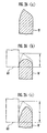
Field of the Invention
The present invention relates to a method and
device for polishing a thin-plate metal ring for use in an
endless belt of a continuously variable transmission.
Description of the Related Art
For example, a plurality of elements
stacked/arranged in an annular form and bound by a
laminated ring constituted by stacking a plurality of metal
rings have been used in a belt for power transmission for
use in a continuously variable transmission. The metal
ring constituting this type of laminated ring is formed in
an endless band shape by slicing a cylindrical metal drum
every predetermined width by a thin disc shaped grinding
stone. Moreover, since burrs are generated in a side edge
of the metal ring cut from the cylindrical drum, it is
necessary o polish the burrs. Even when a few burrs are
generated in the side edge of the metal ring, it is
necessary to polish the side edge of the metal ring and to
finish the side edge in a high-precision curved shape.
As a conventional method of polishing the side
edge of the metal ring, a method described, for example, in
Japanese Patent Laid-Open No. 2001-241512 is known. This
polishing method of the metal ring is called barrel
polishing, the metal rings which are works are mixed in a
barrel filled with the grinding stones called media, and
the barrel is rotated together with the metal rings and
media. When the metal rings are stirred together with the
media in the barrel in this manner, the media are brought
into contact with the side edges of the metal rings to
polish the side edges of the metal rings.
However, when the barrel polishing is performed,
more media abut on an outer peripheral surface side rather
than the inner side of the metal ring, and this causes a
disadvantage that the polishing of inner and outer corners
of the side edge of the metal ring becomes nonuniform.
When the metal rings are projected into the barrel, and at
the time of the barrel polishing, there is a possibility
that the metal rings collide with one another and are
scratched. These metal rings are removed by inspection,
but have been causes for deterioration of yield.
On the other hand, in Japanese Patent Laid-Open No.
2002-248522, a method of polishing the side edge of the
metal ring by the grinding stone is disclosed. However,
for the polishing by the grinding stone, since a shape of
the side edge of the metal ring is influenced by that of
the grinding stone, it is frequently necessary to change
the grinding stone, and there is a disadvantage that
operation efficiency drops.
To solve the disadvantages, an object of the
present invention is to provide a method and device for
polishing a metal ring, in which a side edge of the metal
ring can be polished without performing barrel polishing or
polishing by a grinding stone to solve the above-described
disadvantages.
SUMMARY OF THE INVENTION
To achieve the object, according to the present
invention, there is provided a method of polishing a thin-plate
cylindrical metal ring for use in an endless belt of
a continuously variable transmission, comprising a
projecting step of projecting the metal ring, a first brush
polishing step of polishing one edge of the metal ring
projected in the projecting step by a polishing brush, an
inverting step of inverting the metal ring whose one edge
is polished in the first brush polishing step, a second
brush polishing step of polishing the other edge of the
metal ring inverted in the inverting step by the polishing
brush, and a clearing step of clearing the metal ring whose
other edge is polished in the second brush polishing step.
According to the polishing method of the present
invention, first, one edge of the metal ring is polished by
the first brush polishing step. Subsequently, the metal
ring is inverted by the inverting step, and the other edge
of the metal ring is polished by the second brush polishing
step. Since the side edge of the metal ring is polished by
the polishing brush in the first and second brush polishing
steps, different from the conventional barrel polishing,
there is no possibility that grinding stones stick to the
surface of the ring, and the ring can be polished with good
precision. Additionally, since the inverting step is
disposed, one edge and the other edge of the metal ring can
efficiently be polished.
The method of the present invention is
characterized in that in the first and second brush
polishing steps, the metal ring is held substantially in a
circular shape and rotated in a circumferential direction,
further the polishing brush formed in an annular shape
having a diameter larger than that of the metal ring to
rotate is allowed to abut on the metal ring so as to cross
the edge of the rotating metal ring, and the polishing
brush crosses the edge of the rotating metal ring. At this
time, the polishing brush enters the metal ring at a
predetermined incidence angle with respect to a track of
the rotating metal ring, passes between an inner peripheral
surface of the metal ring and a rotation center of the
metal ring, and leaves the metal ring at a predetermined
outgoing angle with respect to the track of the metal ring.
At this time, the incidence angle and the outgoing
angle are preferably 20° to 45°.
When the incidence angle and outgoing angle are
less than 20°, a polishing amount of the side edge of the
metal ring is reduced, and therefore a speed of the
polishing brush has to be raised or a polishing time has to
be lengthened. When the incidence angle is less than 20°,
the polishing brush also abuts on the inner peripheral
surface of the metal ring to polish the inner peripheral
surface. On the other hand, when the incidence angle and
outgoing angle exceed 45°, only a vertex of the side edge
of the metal ring is polished, and satisfactory chamfering
cannot be carried out. Therefore, when the incidence angle
and outgoing angle of the polishing brush with respect to
the metal ring are set to be 20° to 45°, the side edge of
the metal ring can satisfactorily be chamfered.
Moreover, in the method of the present invention,
the metal ring projected in the projecting step is formed
by cutting out a thin plate cylindrical metal drum into
round slices by a cut-out step disposed before the
projecting step, and it is preferable to push/cut the metal
drum with a cutter whose blade surface has a crow's foot
shape in the cut-out step.
When the metal drum is cut by a thin disc shaped
grinding stone to cut out the metal ring as in the related
art, the side edge of the metal ring has a quadrangular
shape, and therefore a shaving margin has to be increased
in order to chamfer the side edge of the metal ring from
this state. In the present invention, the metal ring is
pushed/cut by a cutter whose blade surface has the crow's
feet shape, therefore the shape of the cutter is
transferred to the side edge of the metal ring and the
metal ring is brought into a chamfered state. Therefore,
the shaving margin can be reduced as compared with the side
edge is cut by the grinding stone as in the related art.
Moreover, the method of the present invention is
characterized in that in the first and second brush
polishing steps, a load current value of a motor for
rotating the polishing brush is detected, when the
polishing brush abuts on the metal ring, and a cut-in
amount of the polishing brush into the metal ring is
increased or decreased so that the detected load current
value is a load current value in a predetermined range.
In the first and second brush polishing steps, as
a substitute characteristic of a motor rotation axis torque
indicating a polishing force for controlling a polished
shape, the cut-in amount of the polishing brush into the
metal ring is increased or decreased in accordance with the
load current value detected from the motor of the polishing
brush. That is, when the polishing brush rotates while
abutting on the side edge of the metal ring to perform the
polishing, the motor of the polishing brush is loaded. The
load on the motor is detected as the load current value of
the motor. At this time, when the cut-in amount of the
polishing brush into the metal ring is large, the load
current value of the motor becomes large. When the cut-in
amount is small, the load current value also becomes small.
On the other hand, when the cut-in amount of the polishing
brush into the metal ring is large, the polishing amount of
the side edge of the metal ring by the polishing brush is
large. When the cut-in amount is small, the polishing
amount also becomes small. Therefore, with the large load
current value of the motor, it can be confirmed that the
polishing amount is large. When the load current value of
the motor is small, it can be confirmed that the polishing
amount is small. From this, the range of the load current
value (the load current value in the predetermined range)
from which a satisfactory polishing amount is obtained can
be determined beforehand.
Moreover, for example, when the polishing brush is
worn, the load current value of the motor decreases.
Therefore, when the cut-in amount of the polishing brush
into the metal ring is accordingly increased, a
predetermined polishing amount can be obtained even with
the worn polishing brush. When the cut-in amount of the
polishing brush into the metal ring is increased or
decreased so as to bring the load current value of the
motor into a preset predetermined range in this manner, the
predetermined polishing amount can be obtained without
being influenced by a worn state of the polishing brush.
Moreover, in the present invention, prior to the
first and second brush polishing steps, the method
comprises a step of measuring a first current value of the
motor, when the polishing brush is in a non-abutting state
with respect to metal ring and the polishing brush is
rotated, a step of measuring the polishing amount and a
second current value of the motor, when the polishing brush
is allowed to abut on the metal ring to polish the edge of
the metal ring, a step of setting an increase of the second
current value with respect to the first current value as
the load current value to calculate a correlation between
the load current value and the polishing amount, and a step
of setting the load current value in the predetermined
range in each brush polishing step based on the calculated
correlation between the load current value and polishing
amount.
The load current value of the motor can easily be
obtained from the increase of the second current value with
respect to the first current value. The range of the load
current value at a time when the predetermined polishing
amount is obtained can easily be obtained from the
correlation between the load current value and polishing
amount. When the range of the load current value obtained
in this manner is set prior to each brush polishing step,
the cut-in amount of the polishing brush into the metal
ring can exactly be increased/decreased in accordance with
the load current value in each brush polishing step.
Moreover, according to the present invention,
there is provided an device for polishing a thin-plate
cylindrical metal ring for use in an endless belt of a
continuously variable transmission, comprising holding
means for exposing one edge of the metal ring and
detachably holding the metal ring to rotate the metal ring
in a peripheral direction, and a polishing brush which is
formed in an annular shape having a diameter larger than
that of the metal ring and which abuts on the edge of the
metal ring while rotating so as to cross the edge of the
metal ring rotated by the holding means.
According to the device of the present invention,
since the edge of the metal ring is polished by the
polishing brush, there is not a possibility that grinding
stones stick to a ring surface as in a conventional barrel
polishing, and high-precision polish processing can
efficiently be carried out.
Moreover, the device of the present invention
comprises a holding table for detachably holding the metal
ring while one edge of the ring is exposed, projecting
means for projecting the metal ring into the holding table,
first polishing means for polishing one edge of the metal
ring held by the holding table by a polishing brush,
inverting means for inverting the metal ring whose one edge
is polished by the first polishing means and allowing the
holding table to hold the metal ring while the other edge
of the ring is exposed, second polishing means for
polishing the other edge of the metal ring inverted by the
inverting means and held by the holding table by the
polishing brush, and clearing means for clearing the metal
ring whose other edge is polished by the second polishing
means from the holding table.
Since the metal ring is held by the holding table
and polished by the polishing brushes of the first and
second polishing means, the metal rings do not collide with
each other as in the conventional barrel polishing, the
metal rings are prevented from being damaged and the edges
of the metal rings can be polished with good precision.
In the device of the present invention, the
holding table includes holding means for detachably holding
the metal ring to rotate the metal ring in the peripheral
direction, each of the first and second polishing means
includes the polishing brush formed in the annular shape
having a diameter larger than that of the metal ring to
rotate, and the polishing brush is allowed to abut on the
metal ring so as to cross the edge of the metal ring
rotated by the holding means.
Accordingly, the rotating polishing brush crosses
and abuts on the metal ring. Additionally, when the
polishing brush abuts on the metal ring, the metal ring is
rotated in the peripheral direction by the holding means,
and therefore the metal ring can efficiently be polished
over the whole periphery by the polishing brush.
Moreover, in the device of the present invention,
the holding table includes a plurality of the holding means
arranged at predetermined intervals on the same
circumference, and the polishing brush is formed in such a
diameter that the polishing brush simultaneously abuts on
the respective metal rings held by the holding means on the
holding table.
Accordingly, since the plurality of metal rings
can be held on the holding table, and the plurality of
metal rings on the holding table can be polished by one
polishing brush, an operation efficiency of the polishing
can rapidly be enhanced.
Moreover, according to one mode in the device of
the present invention, a plurality of the holding tables
are arranged at predetermined intervals around a rotation
axis of a turntable which intermittently rotates every
predetermined angle, and the projecting means, the first
polishing means, the inverting means, the second polishing
means and the clearing means are successively arranged
toward downstream from upstream along a rotation track of
each holding table rotated by the turntable.
Accordingly, since the opposite edges of the metal
ring are polished by one rotation of the turntable, the
operation relating to the polishing can be performed with
good efficiency, and further the device can be constituted
to be compact.
Moreover, according to another mode in the device
of the present invention, the device includes a first
turntable including a plurality of holding tables arranged
at the predetermined intervals around the rotation axis and
intermittently rotating every predetermined angle, and a
second turntable disposed adjacent to the first turntable
and including a plurality of holding tables at the
predetermined intervals around the rotation axis to
intermittently rotate every predetermined angle. The
projecting means and the first polishing means are
successively arranged toward downstream from upstream along
the rotation track of each holding table rotated by the
first turntable. The second polishing means and the
clearing means are successively arranged toward downstream
from upstream along the rotation track of each holding
table rotated by the second turntable. The inverting means
inverts the metal ring on the holding table positioned in
the downstream of the first polishing means of the first
turntable, and transfers the metal ring onto the holding
table positioned in the upstream of the first polishing
means of the second turntable.
Accordingly, while the first turntable rotates
once, one edge of the metal ring is polished. While the
second turntable rotates once, the other edge of the metal
ring is polished. Therefore, an operation interval per
turntable can be relatively broadened, and, for example, a
plurality of first polishing means can be disposed to
enhance the polishing precision of the metal ring.
Moreover, as another mode of the device of the
present invention, each of the projecting means, the first
polishing means, the inverting means, the second polishing
means and the clearing means includes the holding table,
and transfer means is disposed between the holding tables
disposed adjacent to each other to transfer the metal ring
to the other holding table from one holding table.
Accordingly, when the transfer means transfers the
metal ring to the other holding table from one holding
table, the metal ring is removed from one holding table,
and therefore other operations such as cleaning of the
holding table from which the metal ring is removed can
easily be inserted.
In this case, the projecting means, the first
polishing means, the inverting means, the second polishing
means and the clearing means are substantially linearly
arranged.
Additionally, the holding table is circulated
along an endless transfer path for intermittent transfer
every predetermined distance, and the projecting means, the
first polishing means, the inverting means, the second
polishing means and the clearing means may successively be
arranged toward downstream from upstream of each stop
position of the holding table transferred by the transfer
path.
Accordingly, the other operations such as the
cleaning of the holding table from which the metal ring is
removed can easily be inserted.
It is to be noted that in the present invention
each of the first and second polishing means preferably
includes: coarse polishing means for polishing the edge by
a comparatively largely meshed polishing brush for rough
processing; intermediate polishing means for polishing the
edge by a polishing brush for intermediate processing finer
than the polishing brush for coarse processing subsequently
to the polishing by the coarse polishing means; and finish
polishing means for polishing the edge by a polishing brush
for finish processing finer than the polishing brush for
intermediate processing subsequently to the polishing by
the intermediate polishing means.
Accordingly, in the first polishing means, the
coarse polishing, intermediate polishing, and finish
polishing are carried out in order so that one edge of the
metal ring can be polished with high precision. Also in
the second polishing means, the coarse polishing,
intermediate polishing, and finish polishing are carried
out in order so that the other edge of the metal ring can
be polished with high precision.
The holding table in the device of the present
invention is capable of holding a plurality of metal rings.
The projecting means comprises a transfer path for
transferring the plurality of metal rings, an ascendible or
descendible rise/fall table which is disposed on a terminal
end of the transfer path and on which a forefront metal
ring transferred along the transfer path is laid, a
rotatable disc-shaped holding member disposed so as to be
movable between the rise/fall table and the holding table
while holding the plurality of metal rings, a predetermined
number of housing sections which are arranged around the
rotation axis of the holding member in accordance with a
holding position of each metal ring of the holding table
and which are formed in a diameter larger than that of the
metal ring to house the metal ring, lifting means for
lifting up the rise/fall table to house the metal ring in
the housing section, when the holding member is positioned
above the rise/fall table and any of the housing sections
of the holding member is opposed to the metal ring on the
rise/fall table, pressure contact holding means which is
disposed in each housing section to pressure-contact an
outer peripheral wall of the metal ring housed in the
housing section and holds the metal ring in the housing
section and which releases the pressure contact onto the
outer peripheral wall of the metal ring in the holding
position of the holding table, rotating means for rotating
the holding member so as to dispose the non-housing housing
section opposite to the metal ring on the rise/fall table
after holding the metal ring in the housing section; and
moving means for moving the holding member to the holding
table from the rise/fall table after holding the metal ring
in each housing section of the holding member.
When the metal ring of the transfer path is
projected into the holding table by the projecting means,
first the forefront metal ring is laid on the rise/fall
table in the terminal end of the transfer path. On the
other hand, the holding member is positioned above the
rise/fall table. At this time, a state is assumed in which
the metal ring on the rise/fall table is opposite to the
housing section of the holding member. Subsequently, the
rise/fall table is raised by the lifting means, and the
metal ring is housed in the housing section of the holding
member. At this time, the metal ring is held in the
housing section by the pressure contact holding means
disposed in the housing section. Subsequently, the
rise/fall table is moved down, and the forefront metal ring
is laid on the rise/fall table in the terminal end of the
transfer path. Moreover, the holding means is rotated by
the rotating means until the non-housing housing section
(i.e., the housing section in which the metal ring is not
housed) is positioned opposite to the metal ring on the
rise/fall table, and the metal ring is transferred into the
housing section by the raising of the rise/fall table in
the same manner as described above. This can be repeated
to house the metal rings into all the housing sections.
Thereafter, the holding member moves onto the holding table
by the transfer means, and the pressure contact of the
pressure contact holding means of each housing section onto
each metal ring is released. This releases the holding of
each metal ring in the holding member, and the respective
metal rings are simultaneously transferred onto the holding
table.
In this manner, according to the present invention,
after holding the metal ring in all of the housing sections
of the holding member, the holding member is moved toward
the holding table. Therefore, since the metal ring can be
projected into the predetermined holding position of the
holding table only one movement of the holding member for
the transferring, a plurality of metal rings can
efficiently be projected. Additionally, since the pressure
contact holding means pressure-contacts the outer
peripheral wall of the metal ring to hold the metal ring in
each housing section of the holding member, a structure can
be simplified and constituted to be compact as compared
with conventional grasping means for grasping the metal
ring.
Also in the projecting means, an even number of
the housing sections are disposed in accordance with the
holding position of each metal ring of the holding table in
the holding member, and for the rise/fall table, one pair
of metal rings are preferably laid on positions
corresponding to any pair of housing sections of the
holding member.
Accordingly, since the rings are transferred to
the holding means from the rise/fall table every pair, the
number of lifting/lowering operations of the rise/fall
table and the number of stops of the holding member can be
reduced, and efficiency can be enhanced.
Additionally, the rings are transferred to the
even number of housing sections disposed in the holding
member every pair. Therefore, when two columns of rings
are only linearly transferred, two columns of forefront
rings can be laid on the rise/fall table as they are. The
rings can be transferred to one pair of housing sections
from the rise/fall table with good efficiently without
complicating the constitution of the rise/fall table.
Moreover, in the device of the present invention,
the holding table includes holding means for detachably
holding the metal ring and rotating the metal ring in the
peripheral direction. The holding means includes: a laying
base on which the metal ring is laid; a plurality of rails
formed on the laying base so as to extend toward the inner
surface of the metal ring from an axial center side of the
metal ring laid on the laying base; a plurality of abutment
members which are slidably disposed along each rail and
which are capable of abutting on the inner surface of the
metal ring laid on the laying base; and abutment member
driving means for sliding the respective abutment members
along the respective rails to attach or detach each
abutment member with respect to the inner surface of the
metal ring. The abutment member driving means comprises, a
moving member capable of moving in a vertical direction
along an axial center of the metal ring laid on the laying
base, link means for connecting the moving member to each
abutment member to attach each abutment member to the inner
surface of the metal ring when the moving member moves
upwards and to detach each abutment member from the inner
surface of the metal ring when the moving member moves
downwards, urging means for urging the moving member
upwards to attach each abutment member to the inner
peripheral surface of the metal ring via the link means by
an urging force, and holding release means for moving the
moving member downwards against the urging force of the
urging means to detach each abutment member from the inner
peripheral surface of the metal ring via the link means.
According to the holding means, since the
plurality of rails are disposed on the laying base, and a
plurality of abutment members sliding along the respective
rails abut on the inner surface of the metal ring, the
metal ring can be held with good precision. Moreover,
since the holding means includes the abutment member
driving means, the moving member is urged upwards by the
urging means, each abutment member is attached to the inner
peripheral surface of the ring via the link means, and
therefore the high-precision holding state of the metal
ring can securely be maintained.
When the metal ring held on the laying base is
detached from the laying base, the moving member is moved
downwards by the holding release means. Accordingly, the
abutment member is slid into the metal ring by the link
means. When the moving member is simply moved downwards in
this manner, the respective abutment members are detached
from the inner surfaces of the metal rings all at once, and
the holding of the metal rings can be released remarkably
quickly. Additionally, when the link means is simply
disposed between the moving member and each abutment member,
each abutment member can be driven to slide, the structure
is therefore simple and the device can be constituted to be
compact. When the metal ring is held on the non-laying
laying base, the moving means is simply moved downwards by
the holding release means in the same manner. Accordingly,
the abutment members can approach each other. After laying
the metal ring outside each abutment member, the urging
force by the urging means is imparted to the moving means
so that the metal ring can be held remarkably quickly.
Furthermore, a plurality of laying bases are
arranged on the same circumference, and the holding release
means includes another moving member disposed in a central
position of the arrangement circumference of each laying
base so as to be movable in the vertical direction, and a
connecting member for connecting the other moving member to
the moving member of each laying base. The moving member
of each laying base is simultaneously moved downwards by
the downward movement of the other moving member, and each
abutment member of each laying base is simultaneously
detached from the inner peripheral surface of the metal
ring.
Accordingly, when the other moving member is moved
downwards, the moving member of each laying base is
simultaneously moved downwards via the connecting member.
Therefore, even when a plurality of laying bases are
arranged, each laying base can simultaneously hold and
release the metal ring, and the holding operation can
quickly be performed with respect to the plurality of metal
rings with good efficiency.
Moreover, the inverting device in the device of
the present invention includes a ring holding member which
releasably holds the metal ring polished by the first
polishing means and which is movable to a predetermined
position, and moving means for inverting and moving the
ring holding member holding the metal ring to the
predetermined position. The ring holding member includes a
ring holding hole which extends through an axial direction
of the metal ring in accordance with an outer diameter of
the metal ring and which houses the metal ring inside and
which releasably holds the metal ring. The ring holding
hole is characterized in that the metal ring is inserted
via one opening and detached via the other opening.
When the metal ring is polished by the first brush
polishing means, one edge of the metal ring is exposed
upwards. For the metal ring whose one edge is polished in
this state, the other edge not polished yet needs to be
exposed upwards prior to the polishing by the second brush
polishing means. Then, the inverting device holds the
metal ring polished by the first brush polishing means is
held by the ring holding member. The ring holding hole for
housing and holding the metal ring is disposed in the ring
holding member. At this time, the metal ring is inserted
into the ring holding hole via one opening. At this time,
since one edge of the metal ring polished by the first
brush polishing means is exposed upwards, one polished edge
of the metal ring is inserted through one opening of the
ring holding hole directed downwards.
The ring holding member holding the metal ring in
this manner is inverted and moved to the predetermined
position by the moving means. Accordingly, the metal ring
held by the ring holding member is inverted together with
the ring holding member, and one polished edge is directed
downwards. At this time, one opening of the ring holding
hole directed downwards during the insertion of the metal
ring is directed upwards, and simultaneously the other
opening is directed downwards.
Moreover, the metal ring is detached from the
other opening of the ring holding hole directed downwards.
Accordingly, one polished edge of the metal ring is
directed downwards and detached from the other opening of
the ring holding hole, and the other non-polished edge of
the metal ring released from the holding by the ring
holding member is directed upwards.
In this manner, according to the present invention,
the ring holding hole extending through the axial direction
of the metal ring is disposed in the ring holding member,
the metal ring is inserted via one opening of the ring
holding hole, and the metal ring is detached from the other
opening. Therefore, when the ring holding member is simply
inverted, the metal ring can be inverted remarkably quickly.
At this time, the ring holding hole is formed in a
diameter larger than that of the metal ring, and the
pressure contact holding means for pressure-contacting the
outer peripheral wall of the metal ring housed in the ring
holding hole to releasably hold the metal ring is
preferably disposed in the ring holding hole.
According to the pressure contact holding means,
since the metal ring is held with the pressure contact in
the ring holding hole, the metal ring can be held without
obstructing the inserting/detaching of the metal ring with
respect to each opening of the ring holding hole.
Additionally, the metal ring is held in the ring holding
hole by the pressure contact onto the outer peripheral wall
by the pressure contact holding means in the ring holding
hole. Therefore, even when the metal ring is easily
deflected, the metal ring can securely be held
substantially without deforming the metal ring.
Moreover, in the first and second polishing means,
a plurality of metal rings are held in a predetermined
arranged state to polish each metal ring, and the ring
holding member is characterized in that a plurality of the
ring holding holes are disposed in accordance with the
arranged position of each metal ring of the first and
second polishing means.
Accordingly, each ring holding hole can hold the
metal ring while the predetermined arranged state in the
first and second brush polishing devices is maintained, and
therefore the plurality of metal rings can be inverted at
once with good efficiency while maintaining the
predetermined arranged state.
Moreover, in the device of the present invention,
a dressing section for arranging bristles of the polishing
brush can be disposed on the holding table positioned on
the track of the polishing brush. Accordingly, while the
polishing brush polishes the metal ring, the bristles are
arranged by the dressing section. While the polishing
operation is performed, the bristles of the polishing brush
can be arranged without frequently detaching or changing
the polishing brush for performing the dressing operation.
Furthermore, in the device of the present
invention, the dressing section for arranging the bristles
of the polishing brush can be disposed in an abutment
position on the polishing brush in the holding means of the
holding table. Accordingly, the dressing section abuts on
the polishing brush while rotating. Therefore, friction
between the polishing brush and the dressing section is
comparatively large, and the bristles of the polishing
brush can uniformly be arranged with good efficiently in a
slight time for which the polishing brush passes on the
ring holding means. Additionally, the rotating dressing
section accordingly crosses the track of the polishing
brush securely and can be attached to the polishing brush.
Even when a space for disposing the dressing section is
small, the dressing section is simply disposed in a part of
the ring holding means, and the bristles of the polishing
brush can uniformly be arranged securely.
BRIEF DESCRIPTION OF THE DRAWINGS
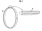
FIG. 1 is an explanatory view showing a metal ring
whose opposite edges are polished in the present embodiment,
FIG. 2 is an explanatory view schematically showing a
polishing device of a first embodiment of the present
invention, FIG. 3 is an explanatory plan view showing a
holding member for projection of projecting means, FIG. 4
is an explanatory view showing an operation of the
projecting means, FIG. 5 is an explanatory plan view of a
holding table, FIG. 6 is an explanatory longitudinal
sectional view of the holding table, FIG. 7 is an
explanatory view showing an operation of holding means of
the holding table, FIG. 8 is an explanatory view showing
another example of the holding means of the holding table,
FIG. 9 is an explanatory sectional view showing polishing
means, FIG. 10 is an explanatory view schematically showing
an operation of a polishing brush, FIG. 11 is an
explanatory view showing a polishing state of the metal
ring by the polishing brush, FIG. 12 is an explanatory side
view of inverting means, FIG. 13 is an explanatory view
showing a holding member for the inverting of the inverting
means, FIG. 14 is an explanatory view showing the operation
of the inverting means, FIG. 15 is an explanatory view
schematically showing a polishing device of a second
embodiment, FIG. 16 is an explanatory view schematically
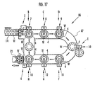
showing the polishing device of a third embodiment, FIG. 17
is an explanatory view schematically showing the polishing
device of a fourth embodiment, FIG. 18 is an explanatory
view showing a relation between tracks of the metal ring
and polishing brush, FIG. 19 is an explanatory view showing
the relation between the tracks of the metal ring and
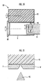
polishing brush, FIG. 20 is an explanatory view showing a
cut-out step of the metal ring from a metal drum, FIG. 21
is an explanatory view showing a cut edge in a state in
which the metal ring is cut out, FIG. 22 is an explanatory
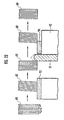
view schematically showing the operation of the holding
table and polishing brush, FIG. 23 is an explanatory view
showing dressing of the polishing brush at a polishing time
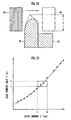
of the metal ring, FIG. 24 is an explanatory view showing a
polishing state of the metal ring by the polishing brush,
FIG. 25 is a graph showing a relation between a cut-in
amount of the polishing brush and a load current value of a
motor, and FIG. 26 is an explanatory view showing a
polishing amount in accordance with the cut-in amount.
DESCRIPTION OF THE PREFERRED EMBODIMENTS
Embodiments of the present invention will be
described with reference to the drawings.
As shown in FIG. 1, a metal ring W is formed in a
thin-plate endless band shape, and is used in an endless
belt of a continuously variable transmission. For the
sectional shape, as shown in an enlarged view of FIG. 1,
opposite edges are polished substantially in a circular
shape.
As shown in FIG. 2, a polishing device 1 in a
first embodiment of the present invention includes a
turntable 2 for transferring the metal rings W. The
turntable 2 is intermittently rotated around a support 3,
and a plurality of holding tables 4 (eight holding tables 4
in the present embodiment) are disposed at a predetermined
interval on a peripheral edge of the turntable. The
holding table 4 holds a plurality of metal rings W (six
metal rings W in the present embodiment) while the rings
are arranged on the same circumference.
For the turntable 2, the metal ring W on the
holding table 4 is stopped for a predetermined time and
afterwards rotated at a predetermined angle for each of
eight stages A to H, and the metal ring W is transferred
among the respective stages A to H. In a rotation
direction of the turntable 2, the stage A positioned in an
uppermost stream is a projecting/clearing stage, and the
projecting/clearing stage A includes projecting means 5 and
clearing means 6. The stage B disposed adjacent to the
downstream of the projecting/clearing stage A is a first
coarse polishing stage, and the first coarse polishing
stage B includes first coarse polishing means 7. The stage
C disposed adjacent to the downstream of the first coarse
polishing stage B is a first intermediate polishing stage,
and the first intermediate coarse polishing stage C
includes first intermediate polishing means 8. The stage D
disposed adjacent to the downstream of the first
intermediate coarse polishing stage C is a first finish
polishing stage, and the first finish coarse polishing
stage D includes first finish polishing means 9. The first
coarse polishing means 7, first intermediate polishing
means 8, and first finish polishing means 9 constitute
first polishing means of the present invention for
polishing first edge of the metal ring W.
The stage E is an inverting stage disposed
adjacent to the downstream of the first finish polishing
stage D, and the inverting stage E includes inverting means
10. Furthermore, the stage F disposed adjacent to the
downstream of the inverting stage E is a second coarse
polishing stage, and the second coarse polishing stage F
includes second coarse polishing means 11. The stage G
disposed adjacent to the downstream of the second coarse
polishing stage F is a second intermediate polishing stage,
and the second intermediate coarse polishing stage G
includes second intermediate polishing means 12. The stage
H disposed adjacent to the downstream of the second
intermediate polishing stage G is a second finish polishing
stage, and the second finish polishing stage H includes
second finish polishing means 13. The second coarse
polishing means 11, second intermediate polishing means 12,
and second finish polishing means 13 constitute second
polishing means of the present invention for polishing the
other edge of the metal ring W.
Next, each component will be described in detail.
As shown in FIG. 2, the projecting means 5 is constituted
by a projecting/transporting conveyor 14 for conveying a
plurality of metal rings W in a projecting direction, and
transfer means for projection 15 for holding the metal ring
W of the projecting/transporting conveyor 14 to transfer
the metal ring W to the holding table 4 positioned in the
projecting/clearing stage A. The transfer means for
projection 15 includes: a holding member for projection 16
for holding a plurality of metal rings W in a state
corresponding to a holding position of the metal ring W of
the holding table 4; a transfer arm 17 for moving the
holding member for projection 16 to the holding table 4
positioned in the projecting/clearing stage A from the
projecting/transporting conveyor 14; and arm driving means
18 for driving the transfer arm 17 so as to rock in
horizontal and vertical directions. It is to be noted that
although not shown, the transfer arm 17 is constituted to
constantly maintain the holding member for projection 16 in
a horizontal state even when rocking the arm in the
horizontal and vertical directions.
As shown in FIG. 3, the holding member for
projection 16 includes a plurality of holding holes 19
formed at predetermined intervals on the same circumference.
The respective holding holes 19 are disposed in six
positions in the present embodiment in accordance with the
holding positions of the metal rings W in the holding table
4. Furthermore, an inner diameter of each holding hole 19
is formed to be larger than an outer diameter of the metal
ring W. The holding member for projection 16 includes a
plurality of cylinders 20 for the respective holding holes
19, and piston rods 21 extended/contracted by the
respective cylinders 20 protrude into the respective
holding holes 19. The metal ring W housed in each holding
hole 19 pressure-contacts an inner peripheral wall of each
holding hole 19 and is held in each holding hole 19 by the
extension of the piston rod 21. The holding member for
projection 16 includes a motor for rotation 22 rotatably
connected to a tip of the transfer arm 17 to intermittently
rotate the arm every predetermined angle.
On the other hand, as shown in FIG. 3, a rise/fall
table 23 is disposed in a terminal end of the
projecting/transporting conveyor 14. The rise/fall table
23 holds one pair of metal rings W aligned in two columns
by an alignment section 24 disposed in a terminal end
portion of the projecting/transporting conveyor 14 and
conveyed to the terminal end of the projecting/transporting
conveyor 14, and is lifted up/down by lifting means (not
shown). The rise/fall table 23 includes a holding convex
portion 25 having a diameter smaller than the inner
diameter of the metal ring W, and a sensor 26 for sensing
the metal ring W held by the holding convex portion 25.
When the metal ring W is sensed by the sensor 26, the
rise/fall table 23 is raised by the lifting means.
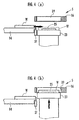
Furthermore, as shown in FIG. 4(a), a stopper 27 protruding
downwards from a bottom portion of the
projecting/transporting conveyor 14 is disposed in the
terminal end of the projecting/transporting conveyor 14.
The stopper 27 engages with the metal ring W positioned in
the terminal end of the projecting/transporting conveyor 14
at the time of the sensing of the metal ring W by the
sensor 26 to stop the advancing of the metal ring W.
When the metal ring W is projected into the
holding table 4 of the turntable 2 by the projecting means
5, first, as shown in FIG. 4(a), the holding member for
projection 16 is position right above the rise/fall table
23. At this time, as shown in FIG. 3, one pair of holding
convex portions 25 of the rise/fall table 23 are opposed to
any pair of holding holes 19 adjacent to each other among
the respective holding holes 19 of the holding member for
projection 16. Subsequently, when the metal ring W is held
by one pair of holding convex portions 25, the rise/fall
table 23 rises by the sensing of the sensor 26, and, as
shown in FIG. 4(b), the metal ring W of one pair of holding
convex portions 25 is housed in one pair of holding holes
19 of the holding member for projection 16. At this time,
as shown in FIG. 3, the cylinders 20 of both the holding
holes 19 operate, the piston rods 21 abut on the metal ring
W, the metal ring W is held in both the holding holes 19,
and then the rise/fall table 23 is moved downwards.
Thereafter, the holding member for projection 16 is rotated
at a predetermined angle by the motor for rotation 22, and
one pair of metal rings W are transferred by the moving
up/down of the rise/fall table 23 shown in FIGS. 4(a) and
4(b). Similarly, one pair of metal rings W are transferred
by the rotating of the holding member for projection 16 and
the moving up/down of the rise/fall table 23, and
accordingly the metal rings W are held in all the holding
holes 19 of the holding member for projection 16.
In this manner, even when the holding member for
projection 16 includes six holding holes 19, the metal
rings W can be held in all of the holding holes 19 of the
holding member for projection 16 by three transfers for
each of one pair of metal rings W, and therefore a
plurality of metal rings W can be held in the holding
member for projection 16 with good efficiency in a short
time.
Thereafter, referring to FIG. 2, the transfer arm
17 rocks in the horizontal direction toward the holding
table 4 positioned in the projecting/clearing stage A, and
further the transfer arm 17 rocks downwards to transfer the
metal ring W to the holding table 4 from the holding member
for projection 16.
Next, a constitution of the holding table 4 will
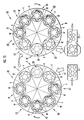
be described in detail. As shown in FIG. 5, the holding
table 4 includes a plurality of (six) holding means 28
arranged at predetermined intervals on the same
circumference in accordance with the holding positions of
the respective metal rings W. The holding means 28 are
constituted to rotatably hold the metal ring W from the
inside. That is, as shown in FIG. 6, the holding means 28
includes: a cylindrical rotation axis 31 rotatably
supported by a frame 29 of the holding table 4 fixed to the
turntable 2 via a plurality of bearings 30; and a rotation
base 32 which is connected to an upper portion of the
rotation axis 31 and on which the metal ring W is laid.
The rotation axis 31 includes a driven gear 33 on
its lower end, and the driven gear 33 is rotated by a
driving motor 36 via an intermediate gear 34 and a driving
gear 35. It is to be noted that the driving motors 36 are
disposed respectively in the above-described stages B, C, D,
F, G, H, and are not disposed in the projecting/clearing
stage A and inverting stage E.
Moreover, a plurality of rocking members 38
rockably supported via support shafts 37 are radially
arranged on the rotation base 32. The rocking member 38
includes a first extending portion 39 extending in a
diametric direction of the rotation base 32, and a second
extending portion 40 integrally connected to the first
extending portion 39 and bent via the support shaft 37 to
extend upwards. An upper end of the second extending
portion 40 is connected to an abutment member 42 via a
connecting portion 41 (see FIG. 7). The respective
abutment members 42 are radially slidably arranged along a
plurality of rails 32a (see FIG. 7) formed on the rotation
base 32, and slide outwards from the rotation base 32 by
the rocking of the rocking member 38 so that the outer
surface of the rail abuts on the inner peripheral surface
of the metal ring W. The rocking members 38 constitute
link means of the present invention.
Furthermore, a first sliding shaft 43 slidable in
the vertical direction along an axial line is inserted/held
in the rotation axis 31 and rotation base 32. The first
sliding shaft 43 is urged upwards by a spring 44. A
holding portion 45 for holding the end of the first
extending portion 39 of the rocking member 38 is disposed
on the upper end of the first sliding shaft 43. Moreover,
a second sliding shaft 47 urged upwards by a spring 46 is
held in a central portion of each holding means 28. The
second sliding shaft 47 is connected to a lower end of each
first sliding shaft 43 via a connecting member 48 disposed
in the lower end of the second sliding shaft.
An operation of each holding means 28 will be
described. As shown by a virtual line in FIG. 6, when a
pressing protrusion 49 disposed on a middle portion of the
holding member for projection 16 presses the second sliding
shaft 47, the second sliding shaft 47 moves downwards.
Accordingly, each first sliding shaft 43 slides downwards
via the connecting member 48. At this time, as shown in
FIG. 7(a), the holding portion 45 moves downwards to push
downwards the first extending portion 39 of each rocking
member 38. Accordingly, with the rocking of the second
extending portion 40 of each rocking member 38, each
abutment member 42 slides toward the middle of the rotation
base 32. When the metal ring W held in each holding hole
19 of the holding member for projection 16 is laid on the
rotation base 32 in this state, each abutment member 42
enters the metal ring W. Next, referring to FIG. 6, when
the holding of the metal ring W by each holding hole 19 of
the holding member for projection 16 is released, and the
holding member for projection 16 moves upwards, the
pressing of the second sliding shaft 47 by the pressing
protrusion 49 is released. Accordingly, the second sliding
shaft 47 is urged by the spring 46 to slide upwards, and
the depressing of the first sliding shaft 43 is released.
Moreover, as shown in FIG. 7(b), when the first sliding
shaft 43 is urged by the spring 44 to push upwards the
holding portion 45, each rocking member 38 rocks, and each
abutment member 42 slides along the rail 32a to abut on the
inside of the metal ring W. In this manner, in accordance
with the present embodiment, with the moving up/down of the
holding member for projection 16, a plurality of metal
rings W are held by each abutment member 42, and a
plurality of metal rings W can be held on the holding table
4 quickly with good efficiency.
Here, as shown in FIGS. 7(a) and 7(b), when a
sliding distance toward a peripheral edge side from a
central side of the rotation base 32 is set to be
comparatively large, the abutment member 42 is capable of
holding even the metal ring W having a small or large
diameter. Accordingly, when receiving the metal ring W,
the respective abutment members 42 gathered on the center
of the rotation base 32 need to be formed to be
comparatively small. Therefore, when the metal ring W
having the large diameter is held, the interval between the
abutment members 42 increases, and a portion of the metal
ring W positioned between the abutment members 42 is
substantially linearly deformed. This state does not
especially obstruct the polishing, but instead of the
abutment member 42 of the present embodiment, as shown in
FIG. 8, an abutment member 52 integrally including a first
abutment portion 50 which abuts on the inner surface of a
small-diameter metal ring W1 and a second abutment portion
51 which abuts on the inner surface of a large-diameter
metal ring W2 may also be disposed. Accordingly, the
sliding distance of each abutment member 52 toward the
peripheral edge side from the central side of the rotation
base 32 can be comparatively reduced. When the large-diameter
metal ring W is held, the interval between the
abutment members 52 is reduced, and the metal ring W can be
held in an approximately perfect circle shape.
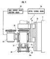
Next, the first coarse polishing means 7 will be
described. The first coarse polishing means 7 is disposed
on the first coarse polishing stage B shown in FIG. 2 to
polish one edge of each metal ring W held by the holding
table 4 stopped on the first coarse polishing stage B. As
shown in FIG. 9, the first coarse polishing means 7
includes: a lifting frame 54 capable of moving up/down
along a rail 53 disposed on the support 3 upright along the
axial line of the turntable 2 (see FIG. 2); a rotating
shaft 57 which is rotatably supported by the lifting frame
54 via a plurality of bearings 55 and whose lower end is
connected to a brush head 56; and a driving motor 59 for
rotating the rotating shaft 57 via a belt 58. The lifting
frame 54 is lowered by the lifting means (not shown) at a
stop time of the turntable 2, and raised at a rotation time
of the motor for rotation 22.
On the brush head 56, polishing brushes 60 each
constituted by bunching nylon linear materials containing
polishing materials are arranged/held in a circular form.
A brush having a small (coarse) count for coarse polishing
is used in the polishing brush 60. As shown in FIG. 10,
the polishing brushes 60 arranged in the circular form as
shown in FIG. 10 rotate have such diameters that the
brushes simultaneously abut on the respective metal rings
on the holding table 4 when rotating. Moreover, when the
brush head 56 shown in FIG. 9 is lowered, as shown in FIG.
10, the polishing brush 60 crosses each metal ring W to
abut on one edge of the ring, and one edge of the metal
ring W is polished over the whole periphery by the
rotations of the polishing brush 60 and metal ring W. At
this time, as shown in FIG. 11, the polishing brush 60
rides over one edge of the metal ring W so that one edge of
the metal ring W is satisfactorily polished.
It is to be noted that the brush head 56 shown in
FIG. 9 may be controlled by the driving motor 59 so as to
alternately repeat forward and reverse rotations.
Concretely, after rotating the polishing brushes 60
clockwise to polish the metal rings W for a predetermined
time, the polishing brushes 60 are rotated counterclockwise
and polished for a predetermined time. When the polishing
brushes 60 are rotated clockwise and counterclockwise in
this manner, the metal rings W can be evenly polished, and
moreover the polishing brushes 60 can be prevented from
being curled.
Moreover, the first intermediate polishing means 8
and first finish polishing means 9 are different only in
the count (fineness) of the polishing brush 60, and the
other constitution is similar to that of the first coarse
polishing means 7. That is, referring to FIG. 2, the
polishing brush 60 of the first intermediate polishing
means 8 having a count larger (finer) than that of the
polishing brush 60 of the first coarse polishing means 7 is
used, and the polishing brush 60 of the first finish
polishing means 9 having a count larger (finer) than that
of the polishing brush 60 of the first intermediate
polishing means 8 is used. In the present embodiment,
concretely, it is assumed that the count of the polishing
brush 60 of the first coarse polishing means 7 is #46, the
count of the polishing brush 60 of the first intermediate
polishing means 8 is #120, and the count of the polishing
brush 60 of the first finish polishing means 9 is #320.
Next, the inverting means 10 will be described.
As shown in FIG. 2, the inverting means 10 is disposed on
the inverting stage E, detaches and inverts each metal ring
W from the holding table 4 positioned on the inverting
stage E, and allows the holding table 4 to hold each
inverted metal ring W again. That is, the inverting means
10 includes: a holding member for inversion 62 for holding
the respective metal rings W on the holding table 4 at
once; an inverting arm 63 for supporting the holding member
for inversion 62 to invert the metal ring W via the holding
member for inversion 62; and arm driving means 64 for
driving the inverting arm 63 to rock in the horizontal and
vertical directions. As shown in FIG. 12, the inverting
arm 63 includes a driving motor for inversion 65 for
invertably supporting the disc-shaped holding member for
inversion 62 and for inverting the holding member for
inversion 62. As shown in FIG. 13, the holding member for
inversion 62 includes a plurality of holding holes 66
formed at predetermined intervals on the same circumference.
The respective holding holes 66 are disposed in six
positions in the present embodiment in accordance with the
holding positions of the metal rings W in the holding table
4. Furthermore, the inner diameter of each holding hole 66
is formed to be larger than the outer diameter of the metal
ring W. The holding member for inversion 62 also includes
a plurality of plungers 67 for the respective holding holes
66. The metal ring W housed in each holding hole 66 is
attached to/grasped by each plunger 67 by its outer
periphery. Furthermore, pressing protrusions 68 for
pressing downwards the second sliding shaft 47 (see FIG. 6)
disposed in the holding means 28 of the holding table 4 are
disposed on the front/back of a middle portion of the
holding member for inversion 62.
Moreover, as shown in FIG. 2, the inverting means
10 is connected to cleaning means 69. The cleaning means
69 includes a support arm 70 connected to the inverting arm
63, and a plurality of cleaning nozzles 71 arranged on the
tip of the support arm 70. When the inverting arm 63 of
the inverting means 10 rocks in the horizontal direction
and the holding member for inversion 62 is moved outwards
from above the holding table 4, each cleaning nozzle 71 is
opposed onto the holding table 4 to wash away polishing
wastes sticking to the holding table 4 from which the metal
ring W is removed.
When the metal ring W is inverted by the inverting
means 10, as shown in FIG. 14(a), first the holding member
for inversion 62 is positioned right above the holding
table 4 and lowered by the inverting arm 63. As shown in
FIG. 2, since each holding hole 66 of the holding member
for inversion 62 is opposite to each metal ring W held on
the holding table 4, each metal ring W held on the holding
table 4 is housed in each holding hole 66 by the lowering
of the holding member for inversion 62. Moreover, since
the pressing protrusions 68 of the holding member for
inversion 62 press downwards the second sliding shaft 47 in
the same manner as in the operation of the holding means 28
by the holding member for projection 16 shown in FIG. 6,
each metal ring W held by each holding means 28 is released.
Moreover, as shown in FIG. 14(b), the metal ring W is
engaged with the plurality of plungers 67 in each holding
hole 66 of the holding member for inversion 62, and the
metal ring W is held in each holding hole 66.
Next, the holding member for inversion 62 is
raised and horizontally moved outwards from above the
holding table 4 by the inverting arm 63, as shown in FIG.
14(c), the holding member for inversion 62 is inverted by
the driving of the driving motor for inversion 65 shown in
FIG. 12. Accordingly, the metal ring W in each holding
hole 66 of the holding member for inversion 62 is inverted.
During this, as shown in FIG. 2, the holding table 4 on
which the metal ring W is not held is cleaned as described
above. Moreover, the inverted holding member for inversion
62 is moved and lowered to an upper position of the holding
table 4 by the inverting arm 63. Accordingly, each holding
means 28 of the holding table 4 holds the metal ring W
whose non-polished other edge is exposed upwards. When the
holding member for inversion 62 is simply inverted, a
plurality of metal rings W can be inverted with remarkably
good efficiency.
In the downstream of the inverting means 10, as
shown in FIG. 2, the second coarse polishing means 11,
second intermediate polishing means 12, and second finish
polishing means 13 are disposed. Since these polishing
means 11, 12, 13 have constitutions similar to those of the
first coarse polishing means 7, first intermediate
polishing means 8, and first finish polishing means 9, the
description thereof is omitted.
Next, the clearing means 6 will be described. As
shown in FIG. 2, the clearing means 6 is constituted by a
clearing/transporting conveyor 72 for conveying a plurality
of metal rings W in a clearing direction, and transfer
means for clearing 73 which holds the metal rings W held on
the holding table 4 positioned on the projecting/clearing
stage A to transfer the ring to a start end of the
clearing/transporting conveyor 72. The transfer means for
clearing 73 includes: a holding member for clearing 74 for
holding a plurality of metal rings W in a state opposed to
the holding position of the metal ring W of the holding
table 4; a transfer arm 75 for moving the holding member
for clearing 74 to the clearing/transporting conveyor 72
from the holding table 4 positioned on the
projecting/clearing stage A; and arm driving means 76 for
driving the transfer arm 75 to rock in the horizontal and
vertical directions. It is to be noted that although not
shown, the transfer arm 75 includes a constitution for
constantly maintaining the holding member for clearing 74
in a horizontal state, even when rocked in the horizontal
and vertical directions. The holding member for clearing
74 includes a constitution similar to that of the holding
member for projection 16 shown in FIG. 3. It is to be
noted that the holding member for clearing 74 is non-rotatably
connected to the tip of the transfer arm 75.
Moreover, the clearing means 6 is connected to
cleaning means 77. The cleaning means 77 includes a
support arm 78 connected to the transfer arm 75, and a
plurality of cleaning nozzles 79 disposed on the tip of the
support arm 78. Each cleaning nozzle 79 is opposed onto
the holding table 4, when the transfer arm 75 of the
clearing means 6 rocks in the horizontal direction and the
holding member for clearing 74 is moved onto the
clearing/transporting conveyor 72 from above the holding
table 4, and washes away the polishing wastes sticking to
the holding table 4 from which the metal ring W is removed.
In accordance with the polishing device 1 of the
present embodiment constituted as described above, as shown
in FIG. 2, first the projecting means 5 projects the metal
ring W onto the holding table 4 positioned on the
projecting/clearing stage A of the turntable 2 (projecting
step). Accordingly, the metal ring W is held by the
holding table 4 in a state in which one end of the ring is
directed upwards. Next, when the holding table 4 holding
the metal ring W stops on the first coarse polishing stage
B by the intermittent rotation of the turntable 2, the
first coarse polishing means 7 coarsely polishes one end of
the metal ring W by the polishing brush 60. Similarly, the
intermediate polishing is carried out by the polishing
brush 60 of the first intermediate polishing means 8 in the
first intermediate polishing stage C, and the finish
polishing is carried out by the polishing brush 60 of the
first finish polishing means 9 in the first finish
polishing stage D (first brush polishing step).
Thereafter, when the holding table 4 holding the
metal ring W whose one edge has been polished is stopped on
the inverting stage E, the inverting means 10 inverts the
metal ring W (inverting step). Accordingly, the metal ring
W is held by the holding table 4 in a state in which the
other end is directed upwards. Subsequently, when the
metal ring W on the holding table 4 is conveyed onto the
second coarse polishing stage F by the intermittent
rotation of the turntable 2, the other end of the metal
ring W is coarsely polished by the polishing brush 60 of
the second coarse polishing means 11. Similarly, when the
metal ring is successively conveyed to the second
intermediate polishing stage G and second finish polishing
stage H, the brush polishing of the other edge of the metal
ring W is completed (second brush polishing step).
Moreover, the metal ring W whose opposite edges have been
polished is cleared from the turntable 2 by the clearing
means 6. In this manner, in accordance with the present
embodiment, the brush polishing of the opposite edges of
the metal ring W is remarkably efficiently performed.
Since the metal rings W do not collide with each other or
media do not stick as in the conventional barrel polishing,
a high-precision polishing can be performed.
Next, a second embodiment of the present invention
will be described with reference to FIG. 15. As shown in
FIG. 15, a polishing device 80 of the second embodiment
includes a first turntable 81 and a second turntable 82
disposed adjacent to the first turntable 81. The first
turntable 81 and second turntable 82 have a constitution
similar to that of the turntable 2 of the first embodiment,
and the holding table 4 and holding means 28 disposed in
the first turntable 81 and second turntable 82 are also
constituted in the same manner as in the first embodiment.
The other components described in the first embodiment are
denoted with the same reference numerals in the drawing to
omit the description thereof.
The first brush polishing step of polishing one
edge of the metal ring W is performed in the first
turntable 81, and the second brush polishing step of
polishing the other edge of the metal ring W is performed
in the second turntable 82. The first turntable 81
intermittently rotates via eight stages A1, B1, B2, C1, C2,
D, E1, I1 which are stop positions. The eight stages A1,
B1, B2, C1, C2, D, E1, I1 in the first turntable 81 are the
projecting stage A1, brush forward rotation coarse
polishing stage B1, brush reverse rotation coarse polishing
stage B2, brush forward rotation intermediate polishing
stage C1, brush reverse rotation intermediate polishing
stage C2, finish polishing stage D, clearing (inverting)
stage E1, and cleaning stage I1 in order. It is to be
noted that the projecting means is disposed on the
projecting stage A1 in the same manner as in the first
embodiment although not shown. The first coarse polishing
means having the same constitution are respectively
disposed on the brush forward rotation coarse polishing
stage B1 and brush reverse rotation coarse polishing stage
B2. The brush forward rotation intermediate polishing
stage C1 and brush reverse rotation intermediate polishing
stage C2 have the first intermediate polishing means having
the same constitution. Moreover, the finish polishing
stage D includes first finish polishing means, and the
cleaning stage I1 includes cleaning means.
Similarly, the second turntable 82 also
intermittently rotates via eight stages E2, F1, F2, G1, G2,
H, A2, I2 which are the stop positions. The eight stages
E2, F1, F2, G1, G2, H, A2, I2 in the second turntable 82
are the projecting (inverting) stage E2, brush forward
rotation coarse polishing stage F1, brush reverse rotation
coarse polishing stage F2, brush forward rotation
intermediate polishing stage G1, brush reverse rotation
intermediate polishing stage G2, finish polishing stage H,
clearing stage A2, and cleaning stage I2 in order. It is
to be noted that inverting means is disposed between the
clearing stage E1 in the first turntable 81 and the
projecting stage E2 in the second turntable 82.
In the brush forward rotation coarse polishing
stages B1, F1 and the brush reverse rotation coarse
polishing stages B2, F2, the respectively disposed
polishing means have the same constitution, but are
different with forward/reverse rotation directions of the
polishing brush 60. In this manner, an abutment direction
of the polishing brush 60 with respect to the metal ring W
does not deviate in one direction, and high-precision
polishing is possible. In the same manner as in the brush
forward rotation intermediate polishing stages C1, G1 and
the brush reverse rotation intermediate polishing stages C2,
G2, the rotation direction of the polishing brush 60
differs and the ring can be polished with high precision.
Since the metal ring W is not held on the holding table 4
in the cleaning stages I1, I2, the holding table 4 can be
cleaned to securely remove the polishing wastes.
In this manner, since the first turntable 81 and
second turntable 82 are disposed in the polishing device 80
of the second embodiment, a plurality of stages such as the
cleaning stages I1, I2 can additionally be disposed, and
the metal ring W can be polished with higher precision.
Next, a third embodiment of the present invention
will be described with reference to FIG. 16. It is to be
noted that the components already described in the first
embodiment are denoted with the same reference numerals in
FIG. 16 and the description thereof is omitted. In a
polishing device 83 of the third embodiment, as shown in
FIG. 16, seven stages B to H are substantially linearly
arranged without using the turntable 2. The first coarse
polishing stage B includes the first coarse polishing means
7, the first intermediate polishing stage C includes the
first intermediate polishing means 8, and the first finish
polishing stage D includes the first finish polishing means
9. The inverting stage E includes the inverting means 10.
Furthermore, the inverting stage E includes the second
coarse polishing means 11, the second intermediate
polishing stage G includes the second intermediate
polishing means 12, and the second finish polishing stage H
includes the second finish polishing means 13. Moreover,
the holding table 4 and holding means 28 (see FIGS. 5 and
6) having the same constitution as that described in the
first embodiment are disposed in each of the stage B to H.
Moreover, transfer means 84 for transferring the
metal ring W to the other holding table 4 from one holding
table 4 is disposed between the holding table 4 which are
disposed adjacent to each other. The
projecting/transporting conveyor 14 is disposed on the
upstream side of the first coarse polishing stage B, and
the projecting means 5 is disposed between the
projecting/transporting conveyor 14 and the first coarse
polishing stage B. The clearing/transporting conveyor 72
is disposed on the downstream side of the second finish
polishing stage H, and the clearing means 6 is disposed
between the second finish polishing stage H and
clearing/transporting conveyor 72. Each transfer means 84
includes the constitution similar to that of the discharge
means 6.
Since the respective stages B to H are
substantially linearly arranged in the polishing device 83
of the third embodiment, the necessity of the
projecting/clearing stage A such as the turntable 2 of the
polishing device 1 of the first embodiment can be obviated.
When the transfer means 84 transfers the metal ring W to
the other holding table 4 from one holding table 4, the
metal ring W is removed from one holding table 4.
Therefore, when each transfer means 84 includes cleaning
nozzles 85, the cleaning operation of the holding table 4
from which the metal ring W is removed or the polished
metal ring W can easily be inserted.
Next, a fourth embodiment of the present invention
will be described with reference to FIG. 17. It is to be
noted that the components already described in the first
embodiment are denoted with the same reference numerals in
FIG. 17 and the description thereof is omitted. In a
polishing device 86 of the fourth embodiment, an endless
transporting conveyor 87 is disposed instead of the
turntable 2, and the operation is similar to that of the
turntable 2. That is, the transporting conveyor 87
intermittently transports a plurality of holding tables 4
at predetermined intervals along a substantially elliptic
track. In the fourth embodiment, the respective stages B,
C, D in which the first brush polishing step is performed
are arranged in parallel with the stages F, G, H in which
the second brush polishing step is performed, and the
inverting stage E is disposed in a return position between
the first finish polishing stage D and the second coarse
polishing stage F. This obviates the necessity of the
respective transfer means 84 such as the polishing device
83 of the third embodiment, and the device constitution can
be simplified. It is to be noted that in the polishing
device 86 of the fourth embodiment, as shown in FIG. 17,
the holding table 4 which does not hold the metal ring W is
transferred between the second finish polishing stage H and
the first coarse polishing stage B. At this time, although
not shown, the holding table 4 can be cleaned.
It is to be noted that in the above-described
respective embodiments, the first brush polishing means is
constituted of the first coarse polishing means 7, first
intermediate polishing means 8, and first finish polishing
means 9, and the second brush polishing means is
constituted of the second coarse polishing means 11, second
intermediate polishing means 12, and second finish
polishing means 13, but the present invention is not
limited to these. For example, the first brush polishing
means may be constituted of the first coarse polishing
means 7 and first finish polishing means 9, and the second
brush polishing means may also be constituted of the second
coarse polishing means 11 and second finish polishing means
13.
Moreover, as described above with reference to FIG.
10, the polishing brush 60 crosses and abuts on each metal
ring W, and by the rotations of the polishing brush 60 and
metal ring W, one edge of the metal ring W is polished over
the whole periphery. At this time, both an incidence angle
and an outgoing angle of the polishing brush 60 with
respect to the metal ring W are preferably set to 20° to
45°, and exactly in the above-described embodiments, as
shown in FIG. 18, the incidence angle and outgoing angle
are set to about 36°.
Here, a case in which the incidence angle and
outgoing angle of the polishing brush 60 with respect to
the metal ring W are less than 20° and exceed 45° will be
described with reference to FIGS. 19(a) and 19(b). When
the incidence angle and outgoing angle of the polishing
brush 60 with respect to the metal ring W are less than 20°
as shown in FIG. 19(a), the metal ring W does not abut on
the whole polishing brush 60, and the edge of the metal
ring W is insufficiently polished. Additionally, since the
metal ring W enters the polishing brush 60, and the
polishing brush 60 also abuts on both the inner and outer
peripheral surfaces of the metal ring W, there is a
possibility that the inner and outer peripheral surfaces of
the metal ring W are damaged. Moreover, to avoid this
situation, as shown by a virtual line in FIG. 19(a), a
polishing brush 60s with a small outer diameter has to be
used. However, the polishing brush 60s having a small
outer diameter has a large deflection amount, and there is
a possibility that the polishing is insufficient.
On the other hand, when the incidence angle and
outgoing angle of the polishing brush 60 with respect to
the metal ring W exceed 45° as shown in FIG. 19(b), a time
of abutment on the metal ring W by the polishing brush 60
is remarkably small, and the polishing is insufficient all
in all. For this reason, the incidence angle and
outgoing angle of the polishing brush 60 with respect to
the metal ring W are preferably set to 20° to 45°, and are
set to about 36° in the above-described embodiments.
Furthermore, in the above-described embodiments,
the shape of the edge of the metal ring W before the
polishing is chamfered beforehand in order to more
efficiently polish the metal ring W. That is, in each
embodiment, as shown in FIG. 20, a cutting device 88 is
used in such a manner that the cut edge of the metal ring W
has a chamfered shape during the cutting-out of the metal
ring W from a metal drum X. As schematically shown in FIG.
20, the cutting device 88 includes: a holding member 89 for
holding the metal drum X in a cylindrical form; a disc-shaped
cutter 90 whose blade surface has a crow's foot
shape; a cutter holding section 91 for rotatably holding
the cutter 90; and a receiving roller 92 which abuts on the
outer peripheral surface of the metal drum X to rotate with
the rotation of the metal drum X. The receiving roller 92
is formed of a synthetic resin having elasticity, and
presses the metal drum X from an outer peripheral side
during the pushing/cutting of the metal drum X by the
cutter 90 from the inner peripheral side.
Moreover, as shown in FIGS. 20 and 21, the metal
ring W is cut from the metal drum X by the cutter 90.
Concretely, as shown in FIG. 20, while the metal drum X
attached to the holding member 89 is rotated, the cutter 90
is pressed onto the inner peripheral surface of the metal
drum X by the cutter holding section 91. At this time, as
shown in FIG. 21, the outer peripheral surface of the metal
drum X onto which the cutter 90 is pressed is held by the
receiving roller 92. Since the receiving roller 92 is
formed of the synthetic resin having elasticity, the metal
drum X pushed upwards by the cutter 90 is deflected on a
receiving roller 92 side and pushed/cut by the cutter 90.
Accordingly, as shown in FIG. 21, the metal ring W whose
cut edge has a chamfered shape can be obtained. It is to
be noted that in the present embodiment, an example in
which the cutter 90 is pressed onto the inner peripheral
surface of the metal drum X has been described, but in
another example, although not shown, the metal drum X is
held on the inner peripheral surface side, the cutter is
pressed onto the metal drum X from the outer peripheral
surface side, and the metal ring W is cut. Even in this
case, the chamfered cut edge can be formed.
Moreover, in the above-described embodiments, as
shown in FIG. 22, a first dressing portion 93 can be
disposed between the holding means 28 on the holding table
4. A plurality of first dressing portions 93 are disposed
along the track of the polishing brush 60, and formed by
grinding stones which abut on the tip of the rotated
polishing brush 60.
Furthermore, a second dressing portion 94 can be
disposed on the upper surface of each abutment member 42 of
each holding means 28. The second dressing portion 94 is
formed by bonding the grinding stone to the upper surface
of each abutment member 42. Since the holding means 28
rotates, the second dressing portion 94 disposed on the
upper surface of each abutment member 42 also rotates.
Accordingly, although not shown, even when the elongated
second dressing portion 94 is disposed in the vicinity of
the inside of the metal ring W of each abutment member 42,
the rotating second dressing portion 94 surely crosses the
track of the polishing brush 60 and abuts on the polishing
brush 60.
As shown in FIGS. 22 and 23, the rotated polishing
brush 60 contacts the first dressing portion 93 disposed in
the track. When the bristles of the polishing brush 60 are
not aligned, the bristles are shaved and arranged by the
first dressing portion 93.
Furthermore, as shown in FIGS. 22 and 23, the
rotating polishing brush 60 abuts on the second dressing
portion 94 disposed on each abutment member 42 of the
holding means 28 which rotates while holding the metal ring
W. When the second dressing portion 94 rotates integrally
with each abutment member 42 and together with the metal
ring W, the portion crosses the track of the polishing
brush 60 to abut on the polishing brush 60. At this time,
since the second dressing portion 94 rotates and abuts on
the polishing brush 60, friction between the second
dressing portion 94 and the polishing brush 60 is large,
and the second dressing portion 94 can securely arrange the
bristles of the polishing brush 60 with good efficiency in
a short time in which the portion passes on the holding
means 28.
When the first dressing portion 93 or the second
dressing portion 94 is disposed in this manner, the
polishing brush 60 polishes the metal ring W, and
simultaneously the dressing is performed to arrange the
bristles of the polishing brush 60. Therefore, maintenance
operations such as the dressing operation and replacement
while removing the polishing brush 60 can be eased, the
bristles of the polishing brush 60 are aligned, the
bristles uniformly abut on the metal ring W, and polishing
precision can be enhanced.
It is to be noted that, needless to say, the
bristles of the polishing brush 60 can sufficiently be
aligned, even when either one of the first dressing portion
93 and the second dressing portion 94 is disposed.
Moreover, the first coarse polishing means 7 of
the first embodiment in FIG. 9 will be described as the
example. As schematically shown in FIG. 9, load current
value detecting means 95 for detecting the load current
value of the driving motor 59, and lifting control means 96
for controlling the lifting means in accordance with the
current value detected by the load current value detecting
means 95 are arranged in the polishing means 7. The
operations of the load current value detecting means 95 and
lifting control means 96 will be described hereinafter.
In the polishing of the metal ring W, as described
above, after six metal rings W are attached to each holding
means 28 of the holding table 4, each holding means 28 is
rotated, and each metal ring W accordingly rotates. At
this time, the brush head 56 is rotated by driving the
motor 59 (see FIG. 9). Moreover, when the polishing means
7 is lowered, and the polishing brush 60 has a
predetermined cut-in amount with respect to the metal ring
W, the polishing means 7 is fixed. Accordingly, as shown
in FIG. 24, the polishing brush 60 abuts on one side edge
of the metal ring W, the polishing brush 60 rides over one
edge of the metal ring W, and one edge of the metal ring W
is polished.
Additionally, when the metal ring W is polished,
the load current value of the motor 59 changes in
accordance with the wear of the polishing brush 60. Since
the change of the load current value is detected by the
load current value detecting means 95, the lifting control
means 96 lowers the brush head 56 via the lifting means so
that the detected load current value is a load current
value in a predetermined range, and accordingly the cut-in
amount is controlled so as to be constant. It is to be
noted that a component shown by a reference numeral 56a in
FIG. 9 is a support plate which supports a tip portion of
the polishing brush 60. When a predetermined protruding
amount of the polishing brush 60 protruding downwards from
the support plate 56a is set, an appropriate rigidity and
processing force are imparted to the polishing brush 60.
Moreover, to polish the metal ring W, the brush head 56 is
lowered so that the protruding amount of the polishing
brush 60 is constant in accordance with the wear of the
polishing brush 60. Therefore, the cut-in amount into the
metal ring W by the polishing brush 60 is set to be
constant.
Here, the operation of the load current value
detecting means 95 and lifting control means 96 will be
described in further detail. The load current value
detecting means 95 calculates a difference between a
current value (first current value) measured at a time when
the polishing brush 60 is in a non-contact state with
respect to the metal ring W (idling time) and a current
value (second current value) measured at a time when the
polishing brush 60 is brought in the contact state with
respect to the metal ring W (polishing time) to detect the
load current value.
On the other hand, the lifting control means 96
stores the range of the load current value in accordance
with a satisfactory polishing amount based on a correlation
between the load current value and polishing amount
calculated beforehand. That is, when the polishing brush
60 rotates, abuts on the side edge of the metal ring W and
performs the polishing, a load is applied to the motor 59
of the polishing brush 60. The load applied to the motor
59 is detected as the load current value of the motor 59 by
the load current value detecting means 95. At this time,
as shown in FIG. 25, when a cut-in amount L of the
polishing brush 60 into the metal ring W is large, a load
current value I of the motor 59 is also large. When the
cut-in amount L is small, the load current value I is also
small.
Moreover, FIG. 26(a) shows the shape of the side
edge of the metal ring W (before the polishing/processing)
immediately after the ring is cut from the cylindrical
metal drum. As shown in FIG. 26(b), when the cut-in amount
L of the polishing brush 60 into the metal ring W is set to
be small and the polishing is performed, the polishing
amount is small, and the side edge of the metal ring W is
polished in a comparatively large curved shape whose tip
radius is comparatively large. As shown in FIG. 26(c), the
cut-in amount L of the polishing brush 60 into the metal
ring W is set to be large and the polishing is performed,
the polishing amount becomes large, and the side edge of
the metal ring W is polished in a curved shape whose tip
radius is comparatively small. From this, the cut-in
amount L necessary for polishing the side edge into a
satisfactory curved shape can be obtained. Moreover, a
range I1 to I2 of the load current value I can be obtained
from a relation between the cut-in amount L and the load
current value I shown in FIG. 25 so as to obtain a
satisfactory range L1 to L2 of the cut-in amount L.
The lifting control means 96 monitors whether or
not the load current value detected by the load current
value detecting means 95 is in the predetermined range I1
to I2 (range of the load current value corresponding to the
satisfactory polishing amount). When the load current
value is larger than the range upper limit I2, the brush
head 56 is raised, and the cut-in amount L is decreased.
When the load current value is smaller than the range lower
limit I2, the brush head 56 is lowered to increase the cut-in
amount L.
Accordingly, concretely, even when the polishing
brush 60 is worn and the cut-in amount L is small, the
brush head 56 is lowered to increase the cut-in amount L,
and the satisfactory polishing amount can be maintained.
That is, when the polishing brush 60 is worn, as shown in
FIG. 26(b), the cut-in amount L is small, and the load
current value of the motor 59 of the polishing brush 60
drops. The load current value at this time is detected by
the load current value detecting means 95, and sent to the
lifting control means 96. Since the lifting control means
96 lowers the brush head 56 in accordance with the drop of
the load current value, the cut-in amount L increases, and
the satisfactory polishing amount can be obtained as shown
in FIG. 24.
It is to be noted that the lowering limit position
of the brush head 56 is set in the lifting control means 96.
Moreover, to increase the cut-in amount L in accordance
with the load current value detected by the load current
value detecting means 95, when the lowering limit position
of the brush head 56 is exceeded in a case in which the
polishing brush 60 is remarkably worn, it can be easily
judged that the polishing brushes 60 are excessively worn
and that polishing abilities of the polishing brushes 60
excessively drop and that it is a time to change the
brushes.
Industrial Applicability
In the present invention, since a side edge of a
metal ring can be polished with a high precision by a
polishing brush, it is possible to use the present
invention in polishing a thin plate cylindrical metal ring
for use in an endless belt of a continuously variable
transmission.