JP3981069B2 - Metal belt for continuously variable transmission, metal ring manufacturing method, and metal ring shape measuring method - Google Patents
Metal belt for continuously variable transmission, metal ring manufacturing method, and metal ring shape measuring method Download PDFInfo
- Publication number
- JP3981069B2 JP3981069B2 JP2003434282A JP2003434282A JP3981069B2 JP 3981069 B2 JP3981069 B2 JP 3981069B2 JP 2003434282 A JP2003434282 A JP 2003434282A JP 2003434282 A JP2003434282 A JP 2003434282A JP 3981069 B2 JP3981069 B2 JP 3981069B2
- Authority
- JP
- Japan
- Prior art keywords
- metal ring
- metal
- radius
- continuously variable
- variable transmission
- Prior art date
- Legal status (The legal status is an assumption and is not a legal conclusion. Google has not performed a legal analysis and makes no representation as to the accuracy of the status listed.)
- Expired - Fee Related
Links
Images


Classifications
-
- F—MECHANICAL ENGINEERING; LIGHTING; HEATING; WEAPONS; BLASTING
- F16—ENGINEERING ELEMENTS AND UNITS; GENERAL MEASURES FOR PRODUCING AND MAINTAINING EFFECTIVE FUNCTIONING OF MACHINES OR INSTALLATIONS; THERMAL INSULATION IN GENERAL
- F16G—BELTS, CABLES, OR ROPES, PREDOMINANTLY USED FOR DRIVING PURPOSES; CHAINS; FITTINGS PREDOMINANTLY USED THEREFOR
- F16G5/00—V-belts, i.e. belts of tapered cross-section
- F16G5/16—V-belts, i.e. belts of tapered cross-section consisting of several parts
Landscapes
- Engineering & Computer Science (AREA)
- General Engineering & Computer Science (AREA)
- Mechanical Engineering (AREA)
- Transmissions By Endless Flexible Members (AREA)
- General Details Of Gearings (AREA)
Description
本発明は、無端状の金属リングを複数枚積層した金属リング集合体に多数の金属エレメントを支持した無段変速機用金属ベルトと、その金属リングの製造方法と、その金属リングの形状測定方法とに関する。 The present invention relates to a metal belt for continuously variable transmission in which a plurality of metal elements are supported on a metal ring assembly in which a plurality of endless metal rings are stacked, a method for manufacturing the metal ring, and a method for measuring the shape of the metal ring. And about.
かかる無段変速機用金属ベルトの金属リングにおいて、その側端縁に近い部分を金属リングの幅方向外側に向けて徐々に薄くなるように塑性変形させることにより、金属ベルトの曲げに伴う側端縁の圧縮応力および引張応力を低減して疲労寿命の延長を図るものが、下記特許文献1により公知である。
ところで、上記従来のものは、金属リングの側端縁の疲労寿命を曲げ応力に基づいて考察しているにも関わらず、前記側端縁が疲労破損の開始点となる原因であるプーリのV面や金属エレメントのネック部との接触によるヘルツ応力を全く考慮していないため、金属リングの側端縁の疲労寿命を効果的に延長することは困難であった。 By the way, although the said conventional thing considers the fatigue life of the side edge of a metal ring based on a bending stress, the V of the pulley which is a cause of the said side edge becoming a fatigue failure starting point Since the Hertz stress due to contact with the surface and the neck portion of the metal element is not considered at all, it is difficult to effectively extend the fatigue life of the side edge of the metal ring.
本発明は前述の事情に鑑みてなされたもので、無段変速機用金属ベルトの金属リングの側端縁の疲労寿命を効果的に延長することを目的とする。 The present invention has been made in view of the above circumstances, and an object thereof is to effectively extend the fatigue life of the side edge of the metal ring of the metal belt for continuously variable transmission.
上記目的を達成するために、請求項1に記載された発明によれば、無端状の金属リングを複数枚積層した金属リング集合体に多数の金属エレメントを支持した無段変速機用金属ベルトにおいて、径方向外周面および径方向内周面を有する前記金属リングの側端縁を、前記径方向外周面に連なる第1切欠部と前記径方向内周面に連なる第2切欠部とによって先細の薄肉状とし、その先端に所定半径を有する円の一部である円弧状の突出部を前記金属リングの径方向中心面と前記径方向内周面との間に位置するように形成し、前記所定半径を有する円は前記径方向内周面から径方向外側に離れた位置にあり、かつ前記第1切欠部の前記金属リングの幅方向長さは、前記第2切欠部の前記金属リングの幅方向長さよりも長く設定されることを特徴とする無段変速機用金属ベルトが提案される。 In order to achieve the above object, according to the first aspect of the present invention, there is provided a metal belt for continuously variable transmission in which a plurality of metal elements are supported on a metal ring assembly in which a plurality of endless metal rings are stacked. The side edge of the metal ring having a radially outer circumferential surface and a radially inner circumferential surface is tapered by a first cutout portion continuous with the radial outer peripheral surface and a second cutout portion continuous with the radial inner peripheral surface. It is thin-walled, and an arcuate protrusion that is a part of a circle having a predetermined radius at the tip thereof is formed so as to be positioned between the radial center surface of the metal ring and the radial inner peripheral surface , A circle having a predetermined radius is at a position radially outward from the radially inner circumferential surface, and the length in the width direction of the metal ring of the first notch is the length of the metal ring of the second notch. Characterized by being set longer than the length in the width direction That metal belt for a continuously variable transmission is proposed.
また請求項2に記載された発明によれば、請求項1に記載の無段変速機用金属ベルトの金属リングの製造方法であって、前記金属リングの側端縁を押し切りにより切断した後に研磨することで、前記側端縁の突出部に所定の半径を付与することを特徴とする金属リングの製造方法が提案される。 According to a second aspect of the present invention, there is provided a method for manufacturing a metal ring of a metal belt for continuously variable transmission according to the first aspect, wherein the side edge of the metal ring is cut by pressing and polished. Thus, a metal ring manufacturing method is proposed in which a predetermined radius is given to the protruding portion of the side edge.
また請求項3に記載された発明によれば、請求項1に記載の無段変速機用金属ベルトの金属リングの突出部の半径を算出する金属リングの形状測定方法であって、金属リングの側端縁の断面形状を所定間隔を有する複数の測定点の座標として測定する工程と、所定の連続する測定点の座標の移動平均を算出する工程と、前記移動平均を所定間隔で少なくとも3個選出し、それら少なくとも3個の移動平均から突出部の半径を算出する工程とを含むことを特徴とする金属リングの形状測定方法が提案される。 According to a third aspect of the present invention, there is provided a metal ring shape measuring method for calculating a radius of a protrusion of a metal ring of a metal belt for continuously variable transmission according to the first aspect. A step of measuring the cross-sectional shape of the side edge as coordinates of a plurality of measurement points having a predetermined interval, a step of calculating a moving average of coordinates of predetermined continuous measurement points, and at least three of the moving averages at a predetermined interval And a method of measuring the shape of the metal ring, including selecting and calculating a radius of the protrusion from the moving average of at least three of them.
請求項1の構成によれば、金属リングの側端縁を先細の薄肉状とし、その先端に所定半径を有する円の一部である円弧状の突出部を金属リングの径方向中心面と径方向内周面との間に位置するように形成し、かつ前記所定半径を有する円は金属リングの径方向内周面から径方向外側に離れた位置にあるので、金属リングの径方向内周面に接する前記所定半径を有する円がプーリのV面に当接する場合に比べて、その突出部がプーリのV面に当接する位置を金属リングの径方向外側に移動させ、プーリに巻きついた金属リングに作用する曲げによる圧縮応力と、前記突出部がプーリのV面に接触して発生するヘルツ応力との総和を減少させることで、金属リングの疲労寿命を高めることができる。しかも金属リングを積層すると、それらの薄肉状となった側端縁間にオイルを保持する凹部が形成されるため、隣接する金属リングの摺動面を効果的に潤滑して耐久性を更に高めることができる。更に金属リングの側端縁において、径方向外周面に連なる第1切欠部の金属リングの幅方向長さを、径方向内周面に連なる第2切欠部の金属リングの幅方向長さよりも長く設定したので、上層の金属リングの幅広の径方向内周面が下層の金属リングの幅狭の径方向外周面を覆うことにより、クラウニングによる金属リング集合体のセンタリング機能が一層高められる。
According to the configuration of
請求項2の構成によれば、金属リングの側端縁を押し切りにより切断した後に研磨して前記側端縁の突出部に所定の半径を付与するので、所望の側端縁形状を有する金属リング効率良く、かつ精度良く製造することができる。 According to the configuration of the second aspect, since the side edge of the metal ring is cut by pressing and then polished to give a predetermined radius to the protruding portion of the side edge, the metal ring having a desired side edge shape is obtained. It can be manufactured efficiently and accurately.
請求項3の構成によれば、金属リングの側端縁の断面形状を所定間隔を有する複数の測定点の座標として測定し、所定の連続する測定点の座標の移動平均を算出し、前記移動平均を所定間隔で少なくとも3個選出して該少なくとも3個の移動平均から突出部の半径を算出するので、各測定点の座標の検出誤差や、金属リングの突出部の細かい傷の影響を排除し、突出部の半径を精度良く検出することができる。
According to the configuration of
以下、本発明の実施の形態を、添付の図面に示した本発明の実施例に基づいて説明する。 DESCRIPTION OF THE PREFERRED EMBODIMENTS Embodiments of the present invention will be described below based on examples of the present invention shown in the accompanying drawings.
図1〜図8は本発明の一実施例を示すもので、図1は金属ベルト式無段変速機を搭載した車両の動力伝達系のスケルトン図、図2は金属ベルトの部分斜視図、図3は金属リングの押し切り工程の説明図、図4は押し切りされた金属リングと研磨された金属リングとを示す図、図5は実施例および比較例の金属リングがプーリのV面に当接した状態を示す図、図6は実施例および比較例の金属リングに作用する応力を示すグラフ、図7は金属リング集合体の端部の拡大図、図8は金属リングの突出部の半径を測定する手法の説明図である。 1 to 8 show an embodiment of the present invention. FIG. 1 is a skeleton diagram of a power transmission system of a vehicle equipped with a metal belt type continuously variable transmission, and FIG. 2 is a partial perspective view of the metal belt. 3 is an explanatory diagram of a metal ring push-off process, FIG. 4 is a view showing a pressed metal ring and a polished metal ring, and FIG. 5 is a diagram in which the metal ring of the example and the comparative example contacted the V surface of the pulley. FIG. 6 is a graph showing the stress acting on the metal ring of Example and Comparative Example, FIG. 7 is an enlarged view of the end of the metal ring assembly, and FIG. 8 is a measurement of the radius of the protrusion of the metal ring. It is explanatory drawing of the technique to do.
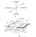
尚、本実施例で用いる金属エレメントあるいは金属リングの前後方向、幅方向、径方向の定義は図2に示されている。径方向はその金属エレメントが当接するプーリの径方向として定義されるもので、プーリのシャフトに近い側が径方向内側であり、プーリのシャフトに遠い側が径方向外側である。また幅方向は金属エレメントが当接するプーリのシャフトに沿う方向として定義され、前後方向は金属エレメントの車両の前進走行時における進行方向に沿う方向として定義される。 In addition, the definition of the front-back direction of the metal element or metal ring used in a present Example, a width direction, and a radial direction is shown by FIG. The radial direction is defined as the radial direction of the pulley with which the metal element abuts. The side closer to the pulley shaft is the radially inner side, and the side farther from the pulley shaft is the radially outer side. The width direction is defined as the direction along the pulley shaft with which the metal element abuts, and the front-rear direction is defined as the direction along the traveling direction of the metal element when the vehicle is traveling forward.
図1に示すように、車両用の金属ベルト式無段変速機Tは平行に配置されたドライブシャフト1およびドリブンシャフト2を備えており、エンジンEのクランクシャフト3の左端はダンパー4を介してドライブシャフト1の右端に接続される。
As shown in FIG. 1, a metal belt type continuously variable transmission T for a vehicle includes a
ドライブシャフト1に支持されたドライブプーリ5は、該ドライブシャフト1に対して相対回転自在な固定側プーリ半体5aと、この固定側プーリ半体5aに対して軸方向摺動自在な可動側プーリ半体5bとを備える。可動側プーリ半体5bは、作動油室6に作用する油圧により固定側プーリ半体5aとの間の溝幅が可変である。ドリブンシャフト2に支持されたドリブンプーリ7は、該ドリブンシャフト2に一体に形成された固定側プーリ半体7aと、この固定側プーリ半体7aに対して軸方向摺動自在な可動側プーリ半体7bとを備える。可動側プーリ半体7bは、作動油室8に作用する油圧により固定側プーリ半体7aとの間の溝幅が可変である。そしてドライブプーリ5とドリブンプーリ7との間に、2本の金属リング集合体に多数の金属エレメントを装着した金属ベルト9が巻き掛けられる。
The drive pulley 5 supported by the
ドライブシャフト1の左端に、前進変速段を確立する際に係合してドライブシャフト1の回転を同方向にドライブプーリ5に伝達するフォワードクラッチ10と、後進変速段を確立する際に係合してドライブシャフト1の回転を逆方向にドライブプーリ5に伝達するリバースブレーキ11とを備えた、シングルピニオン式の遊星歯車機構よりなる前後進切換機構12が設けられる。前後進切換機構12のサンギヤ27はドライブシャフト1に固定され、プラネタリキャリヤ28はリバースブレーキ11によりケーシングに拘束可能であり、リングギヤ29はフォワードクラッチ10によりドライブプーリ5に結合可能である。
A
ドリブンシャフト2の右端に設けられる発進用クラッチ13は、ドリブンシャフト2に相対回転自在に支持した第1中間ギヤ14を該ドリブンシャフト2に結合する。ドリブンシャフト2と平行に配置された中間軸15に、前記第1中間ギヤ14に噛合する第2中間ギヤ16が設けられる。ディファレンシャルギヤ17のギヤボックス18に設けた入力ギヤ19に、前記中間軸15に設けた第3中間ギヤ20が噛合する。ギヤボックス18にピニオンシャフト21,21を介して支持した一対のピニオン22,22に、ギヤボックス18に相対回転自在に支持した左車軸23および右車軸24の先端に設けたサイドギヤ25,26が噛合する。左車軸23および右車軸24の先端にそれぞれ駆動輪W,Wが接続される。
The starting
しかして、セレクトレバーでフォワードレンジを選択すると、電子制御ユニットU1により作動する油圧制御ユニットU2からの指令により、先ずフォワードクラッチ10が係合し、その結果ドライブシャフト1はドライブプーリ5に一体に結合される。続いて発進用クラッチ13が係合し、エンジンEのトルクがドライブシャフト1、ドライブプーリ5、金属ベルト9、ドリブンプーリ7、ドリブンシャフト2およびディファレンシャルギヤ17を経て駆動輪W,Wに伝達され、車両は前進発進する。セレクトレバーでリバースレンジを選択すると、油圧制御ユニットU2からの指令により、リバースブレーキ11が係合してドライブプーリ5がドライブシャフト1の回転方向と逆方向に駆動されるため、発進用クラッチ13の係合により車両は後進発進する。
Thus, when the forward range is selected by the select lever, the
このようにして車両が発進すると、油圧制御ユニットU2からの指令でドライブプーリ5の作動油室6に供給される油圧が増加し、ドライブプーリ5の可動側プーリ半体5bが固定側プーリ半体5aに接近して有効半径が増加するとともに、ドリブンプーリ7の作動油室8に供給される油圧が減少し、ドリブンプーリ7の可動側プーリ半体7bが固定側プーリ半体7aから離反して有効半径が減少することにより、金属ベルト式無段変速機TのレシオがLOW側からOD側に向けて連続的に変化する。
When the vehicle starts in this way, the hydraulic pressure supplied to the
図2に示すように、金属ベルト9は左右一対の金属リング集合体31,31に多数の金属エレメント32…を支持したもので、各々の金属リング集合体31は複数枚の金属リング33…を積層して構成される。金属板材から打ち抜いて成形した金属エレメント32は、エレメント本体34と、金属リング集合体31,31が係合する左右一対のリングスロット35,35間に位置するネック部36と、ネック部36を介して前記エレメント本体34の径方向外側に接続される概略三角形のイヤー部37とを備える。エレメント本体34の左右方向両端部には、ドライブプーリ5およびドリブンプーリ7のV面38…(図5参照)に当接可能な一対のプーリ当接面39,39が形成される。また金属エレメント32の進行方向前側および後側には相互に当接する主面40がそれぞれ形成され、また進行方向前側の主面40の下部には左右方向に延びるロッキングエッジ41を介して傾斜面42が形成される。更に、前後に隣接する金属エレメント32,32を結合すべく、イヤー部37の前後面に相互に嵌合可能な凹凸部43が形成される。そして左右のリングスロット35,35の下縁に、金属リング集合体31,31の内周面を支持するサドル面44,44が形成される。
As shown in FIG. 2, the
次に、金属リング集合体31を構成する金属リング33の製造工程を説明する。
Next, the manufacturing process of the
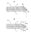
図3に示すように、金属リング33は円筒状に形成された金属リング素材33′を所定幅に輪切りにすることで製造される。即ち、回転するマンドレル51の表面に一対の傾斜部52a,52aと、両傾斜部52a,52aを接続する等径部52bとを備えた円周溝52を形成しておき、マンドレル51の外周に金属リング素材33′を支持した状態で、その外周に断面3角形の刃部53aを有する円板状のカッター53を回転させながら押し付けることで、円周溝52と刃部53aとの協働で金属リング素材33′を押し切りにより切断する。図4(A)に示すように、切断された金属リング33の側端縁は径方向外側に僅かに湾曲するとともに、概ね平坦な二つの面a,bと尖った二つのエッジ33a,33bとが形成される。
As shown in FIG. 3, the
続いて、金属リング33の側端縁を回転する砥粒入りブラシで研磨することで、前記尖った二つのエッジ33a,33bを削り落とし、図4(B)に示すような所定半径Rの円弧状の突出部33cを金属リング33の側端縁に形成する。本実施例において、この突出部33cの位置は、金属リング33の径方向中心面Cと径方向内周面Iとの間にある。
Subsequently, by polishing the side edge of the
金属リング33の側端縁において、径方外周面Oには該金属リング32の幅方向の長さがLaの第1切欠部33eが形成されるとともに、径方内周面Iには該金属リング32の幅方向の長さがLbの第2切欠部33fが形成され、第1、第2切欠部33e,33fの先端に突出部33cが連なっている。また前記第2切欠部33fを設けたことにより、突出部33cを構成する所定半径Rの円は、金属リング33の径方向内周面Iよりも径方向外側に位置している。
At the side edge of the
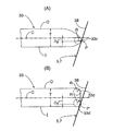
図5(A)は、金属ベルト9がプーリ5,7に巻き付きいて厚さT(例えば、0.2mm)の金属リング33の側端縁がプーリ5,7のV面38に接触した状態を示している。このとき、金属リング33の側端縁の突出部33cとプーリ5,7のV面38との接点Pは、金属リング33の径方向中心面Cよりも、Δyだけ径方向内側にずれている。図6(A)に示すように、プーリ5,7に巻き付くことで湾曲した金属リング33は、その径方向外周面Oが最も引き伸ばされて引張応力が最大になり、その径方向内周面Iが最も押し縮められて圧縮応力が最大になり、かつ径方向中心面Cでは応力がゼロになる。つまり、径方向外周面Oおよび径方向内周面I間で応力はσaから−σaまでリニアに変化する。また突出部33cとプーリ5,7のV面38との接点Pには、接触により圧縮応力(接触応力−σb)が作用する。従って、前記接点Pには、曲げによる圧縮応力|−σa1|と前記接触応力|−σb|との和である|σ|=|−σa1−σb|が作用することになる。
FIG. 5A shows a state in which the
比較例の金属リング33はマンドレルの外周に支持した円筒状の金属リング素材33′を回転砥石により切断したもので、切断時の金属リング33の断面は矩形状となる。この金属リング33をバレル研磨すると、図5(B)に示すように金属リング33の側端縁の径方向外端および径方向内端が研磨されて半径Rを有する二つの角部33d,33dが形成される。
The
図5(B)に示すように、比較例の金属リング33は端縁部の径方向内側の角部33dがプーリ5,7のV面38に接点P′で接触する。前記角部33dがプーリ5,7のV面38に接触する接点P′の位置は、金属リング33の径方向中心面CよりもΔy′だけ径方向内側にずれており、そのずれΔy′は図5(A)に示す実施例のΔyよりも大きくなる。つまり、比較例の接点P′の位置は、実施例の接点Pの位置に比べて金属リング33の径方向内周面Iに近い位置にある。従って、比較例の接点P′には、曲げによる圧縮応力|−σa1′|と前記接触応力|−σb′|との和である|σ′|=|−σa1′−σb′|が作用することになる。
As shown in FIG. 5B, in the
実施例の金属リング33の突出部33cの半径Rと、比較例の角部33dの半径Rとが等しければ、両接触応力|−σb|,|−σb′|は一致するが、接点P,P′の位置が異なることで、実施例の接点Pでの曲げによる圧縮応力|σa1|は、比較例の接点P′での曲げによる圧縮応力|σa1′|よりも小さくなる。従って、実施例の接点Pでのトータルの圧縮応力|σ|=|−σa1−σb|は、比較例の接点P′でのトータルの圧縮応力|σ′|=|−σa1′−σb′|よりも小さくなる。
If the radius R of the protruding
このように、実施例の金属リング33は、比較例33の金属リング33に比べて接点P,P′の接触応力を考慮したトータルの圧縮応力を低減し、繰り返し曲げに対する耐久性を高めることができる。しかも、押し切り工程と研磨工程とを行うことで、所望の側端縁形状を有する金属リング33…を効率良く、かつ精度良く製造することができる。
As described above, the
また図7から明らかなように、複数の金属リング33…を積層した金属リング集合体31の側端縁は、隣接する金属リング33…の突出部33c…間の凹部にオイルが保持され易くなるため、隣接する金属リング33…間の摺動面の潤滑が促進されて耐久性が更に向上する。更に積層状態にある金属リング33…はクラウニングが施された金属エレメント32のサドル面44によって幅方向にセンタリングされるが、その際に、上層の金属リング33の幅広の径方向内周面Iが下層の金属リング33の幅狭の径方向外周面Oを覆うことによりセンタリング機能が一層高められる。
Further, as is apparent from FIG. 7, the side edge of the
次に、完成した金属リング33の側端縁の突出部33aの半径Rが目標値に一致しているか否かを検証する手法について説明する。
Next, a method for verifying whether or not the radius R of the protruding
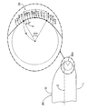
本実施例の金属リング33は、側端縁の突出部33aのうちの半径Rの円弧部分が60°(π/3)の中心角を有するため、その円弧部分の長さLはR×(π/3)となる。
In the
先ず、金属リング33の側端縁の断面の座標を所定ピッチpで測定する。そして連続する複数個(例えば3個)の測定点の座標の移動平均を、測定点を一つずつずらしながら算出する。この移動平均の座標をプロットしたものが図8のm1,m2,m3,…m17であり、そのうち円弧部分の両端に最も近い位置の移動平均m4,m14と、その中央に最も近い位置の移動平均m9とが求まれば、それら3個の移動平均m4,m9,m14を通る円の半径Rを算出し、それが目標値に一致しているか否かを確認することができる。
First, the coordinates of the cross section of the side edge of the
隣接する移動平均m1〜m17間のピッチpは測定点間のピッチpと同じであるため、円弧部分の長さL=R×(π/3)をピッチpで除算することで、円弧部分の長さLに含まれる移動平均m4〜m14の間隔の数が算出される。ここで移動平均m4〜m14を選択したのは、それらの外側のデータは他の曲率部を含むために誤差を生じるからである。実施例では前記間隔の数が約10個になるため、5個置きの3個の移動平均m4,m9,m14を選択することで、それらの移動平均m4,m9,m14を通る円の半径Rを精度良く算出することができる。 Since the pitch p between the adjacent moving averages m1 to m17 is the same as the pitch p between the measurement points, by dividing the length L = R × (π / 3) of the arc portion by the pitch p, The number of intervals of the moving averages m4 to m14 included in the length L is calculated. The reason why the moving averages m4 to m14 are selected here is that an error occurs because the data outside them includes other curvature parts. In the embodiment, since the number of the intervals is about 10, by selecting every third moving average m4, m9, m14, the radius R of the circle passing through the moving averages m4, m9, m14 is selected. Can be calculated with high accuracy.
特に、移動平均m1〜m17を算出することで、各測定点の座標の検出誤差や、金属リング33の突出部33aの細かい傷の影響を排除し、突出部33aの円弧部分の半径Rを精度良く検出することができる。
In particular, by calculating the moving averages m1 to m17, the detection error of the coordinates of each measurement point and the influence of fine scratches on the protruding
以上、本発明の実施例を詳述したが、本発明はその要旨を逸脱しない範囲で種々の設計変更を行うことが可能である。 As mentioned above, although the Example of this invention was explained in full detail, this invention can perform a various design change in the range which does not deviate from the summary.
例えば、実施例では金属リング33の突出部33aの円弧部分の半径Rを3個の移動平均m4,m9,m14に基づいて算出しているが、4個以上の移動平均に基づいて算出することができる。
For example, in the embodiment, the radius R of the arc portion of the protruding
9 金属ベルト
31 金属リング集合体
33 金属リング
33c 突出部
33e 第1切欠部
33f 第2切欠部
C 金属リングの径方向中心面
I 金属リングの径方向内周面
La 第1切欠部の金属リングの幅方向長さ
Lb 第2切欠部の金属リングの幅方向長さ
O 金属リングの径方向外周面
9
Claims (3)
径方向外周面(O)および径方向内周面(I)を有する前記金属リング(33)の側端縁を、前記径方向外周面(O)に連なる第1切欠部(33e)と前記径方向内周面(I)に連なる第2切欠部(33f)とによって先細の薄肉状とし、その先端に所定半径を有する円の一部である円弧状の突出部(33c)を前記金属リング(33)の径方向中心面(C)と前記径方向内周面(I)との間に位置するように形成し、
前記所定半径を有する円は前記径方向内周面(I)から径方向外側に離れた位置にあり、かつ前記第1切欠部(33e)の前記金属リング(33)の幅方向長さ(La)は、前記第2切欠部(33f)の前記金属リング(33)の幅方向長さ(Lb)よりも長く設定されることを特徴とする無段変速機用金属ベルト。 In a metal belt for continuously variable transmission in which a plurality of endless metal rings (33) are stacked and a plurality of metal elements (32) are supported on a metal ring assembly (31),
A side edge of the metal ring (33) having a radial outer peripheral surface (O) and a radial inner peripheral surface (I) is connected to the first notch (33e) and the diameter. The second notch (33f) connected to the inner circumferential surface (I) is tapered and thinned, and the arc-shaped protrusion (33c), which is a part of a circle having a predetermined radius, is formed on the metal ring ( 33) is formed so as to be positioned between the radial center plane (C) and the radial inner peripheral surface (I) ,
The circle having the predetermined radius is located at a position radially outward from the radially inner circumferential surface (I), and the width direction length (La) of the metal ring (33) of the first notch (33e). ) Is set longer than the length (Lb) in the width direction of the metal ring (33) of the second notch (33f).
前記金属リング(33)の側端縁を押し切りにより切断した後に研磨することで、前記側端縁の突出部(33c)に所定の半径を付与することを特徴とする金属リングの製造方法。 It is a manufacturing method of the metal ring (33) of the metal belt (9) for continuously variable transmission according to claim 1,
A method of manufacturing a metal ring, wherein a predetermined radius is imparted to the protruding portion (33c) of the side end edge by polishing the side end edge of the metal ring (33) after being cut by pressing.
金属リング(33)の側端縁の断面形状を所定間隔を有する複数の測定点の座標として測定する工程と、
所定の連続する測定点の座標の移動平均を算出する工程と、
前記移動平均を所定間隔で少なくとも3個選出し、それら少なくとも3個の移動平均から突出部(33c)の半径を算出する工程と、
を含むことを特徴とする金属リングの形状測定方法。 A metal ring shape measuring method for calculating a radius of a protrusion (33c) of a metal ring (33) of a continuously variable transmission metal belt (9) according to claim 1,
Measuring the cross-sectional shape of the side edge of the metal ring (33) as the coordinates of a plurality of measurement points having a predetermined interval;
Calculating a moving average of coordinates of predetermined continuous measurement points;
Selecting at least three moving averages at predetermined intervals and calculating a radius of the protrusion (33c) from the at least three moving averages;
A method for measuring the shape of a metal ring, comprising:
Priority Applications (5)
| Application Number | Priority Date | Filing Date | Title |
|---|---|---|---|
| JP2003434282A JP3981069B2 (en) | 2003-12-26 | 2003-12-26 | Metal belt for continuously variable transmission, metal ring manufacturing method, and metal ring shape measuring method |
| CNB2004100946927A CN1306184C (en) | 2003-12-26 | 2004-11-12 | Continuously variable transmission metal belt, process for producing metal ring, and process for measuring shape of metal ring |
| DE602004025785T DE602004025785D1 (en) | 2003-12-26 | 2004-12-16 | Metal belt for continuously variable transmission, method of making a metal ring. |
| EP04029910A EP1548325B1 (en) | 2003-12-26 | 2004-12-16 | Continuously variable transmission metal belt, process for producing metal ring. |
| US11/019,385 US7670241B2 (en) | 2003-12-26 | 2004-12-23 | Continuously variable transmission metal belt, process for producing metal ring, and process for measuring shape of metal ring |
Applications Claiming Priority (1)
| Application Number | Priority Date | Filing Date | Title |
|---|---|---|---|
| JP2003434282A JP3981069B2 (en) | 2003-12-26 | 2003-12-26 | Metal belt for continuously variable transmission, metal ring manufacturing method, and metal ring shape measuring method |
Publications (2)
| Publication Number | Publication Date |
|---|---|
| JP2005188712A JP2005188712A (en) | 2005-07-14 |
| JP3981069B2 true JP3981069B2 (en) | 2007-09-26 |
Family
ID=34545098
Family Applications (1)
| Application Number | Title | Priority Date | Filing Date |
|---|---|---|---|
| JP2003434282A Expired - Fee Related JP3981069B2 (en) | 2003-12-26 | 2003-12-26 | Metal belt for continuously variable transmission, metal ring manufacturing method, and metal ring shape measuring method |
Country Status (5)
| Country | Link |
|---|---|
| US (1) | US7670241B2 (en) |
| EP (1) | EP1548325B1 (en) |
| JP (1) | JP3981069B2 (en) |
| CN (1) | CN1306184C (en) |
| DE (1) | DE602004025785D1 (en) |
Cited By (1)
| Publication number | Priority date | Publication date | Assignee | Title |
|---|---|---|---|---|
| US8926404B2 (en) | 2010-06-25 | 2015-01-06 | Honda Motor Co., Ltd. | Method for manufacturing metal ring of continuously variable transmission metal belt |
Families Citing this family (5)
| Publication number | Priority date | Publication date | Assignee | Title |
|---|---|---|---|---|
| US8190075B2 (en) | 2009-09-30 | 2012-05-29 | Canon Kabushiki Kaisha | Endless metallic belt, electrophotographic endless belt, fixing assembly, and electrophotographic image forming apparatus |
| CN102576206B (en) * | 2009-09-30 | 2015-01-07 | 佳能株式会社 | Endless metal belt, endless belt for use in electrophotography, fixing device, and electrophotographic image-forming device |
| JP2015194226A (en) * | 2014-03-31 | 2015-11-05 | 本田技研工業株式会社 | Metal belt for continuously variable transmission |
| AT517952B1 (en) * | 2016-02-23 | 2017-06-15 | Berndorf Band Gmbh | Process for producing endless metal strips of any width |
| WO2019112026A1 (en) * | 2017-12-07 | 2019-06-13 | アイシン・エィ・ダブリュ株式会社 | Transmission belt and continuously variable transmission, method for designing element, and method for producing element |
Family Cites Families (10)
| Publication number | Priority date | Publication date | Assignee | Title |
|---|---|---|---|---|
| JPS6129025A (en) * | 1984-07-20 | 1986-02-08 | 東芝テック株式会社 | key switch device |
| NL8403388A (en) * | 1984-11-07 | 1986-06-02 | Gayliene Investments Ltd | ENDLESS METAL TAPE. |
| JPS61290257A (en) * | 1985-06-17 | 1986-12-20 | Nissan Motor Co Ltd | V-belt |
| JP3361835B2 (en) | 1992-06-17 | 2003-01-07 | 横河電機株式会社 | Switching power supply |
| JPH0743119A (en) | 1993-07-27 | 1995-02-10 | Nkk Corp | Tube size measuring device |
| DE69806226T2 (en) * | 1998-04-14 | 2003-02-20 | Van Doorne's Transmissie B.V., Tilburg | Metallic belt and process for its manufacture |
| JP3534033B2 (en) | 2000-02-29 | 2004-06-07 | 日産自動車株式会社 | Laminated metal belt ring and manufacturing method thereof |
| JP3977023B2 (en) | 2000-03-01 | 2007-09-19 | 本田技研工業株式会社 | Metal belt type continuously variable transmission |
| NL1020809C2 (en) * | 2002-06-07 | 2003-12-17 | Doornes Transmissie Bv | Push belt, ring element, and method and device for electrochemical processing thereof. |
| US7413496B2 (en) * | 2003-02-10 | 2008-08-19 | Honda Motor Co., Ltd. | Method and device for polishing endless belt metal rings for continuously variable transmission |
-
2003
- 2003-12-26 JP JP2003434282A patent/JP3981069B2/en not_active Expired - Fee Related
-
2004
- 2004-11-12 CN CNB2004100946927A patent/CN1306184C/en not_active Expired - Fee Related
- 2004-12-16 DE DE602004025785T patent/DE602004025785D1/en not_active Expired - Lifetime
- 2004-12-16 EP EP04029910A patent/EP1548325B1/en not_active Expired - Lifetime
- 2004-12-23 US US11/019,385 patent/US7670241B2/en not_active Expired - Fee Related
Cited By (1)
| Publication number | Priority date | Publication date | Assignee | Title |
|---|---|---|---|---|
| US8926404B2 (en) | 2010-06-25 | 2015-01-06 | Honda Motor Co., Ltd. | Method for manufacturing metal ring of continuously variable transmission metal belt |
Also Published As
| Publication number | Publication date |
|---|---|
| DE602004025785D1 (en) | 2010-04-15 |
| CN1637315A (en) | 2005-07-13 |
| EP1548325A2 (en) | 2005-06-29 |
| EP1548325A3 (en) | 2005-09-07 |
| CN1306184C (en) | 2007-03-21 |
| US20050170926A1 (en) | 2005-08-04 |
| JP2005188712A (en) | 2005-07-14 |
| EP1548325B1 (en) | 2010-03-03 |
| US7670241B2 (en) | 2010-03-02 |
Similar Documents
| Publication | Publication Date | Title |
|---|---|---|
| EP1884682B1 (en) | Power transmission chain, method for manufacturing power transmission member of the power transmission chain, and power transmission device | |
| JP6540832B2 (en) | Transmission belt | |
| JP3981069B2 (en) | Metal belt for continuously variable transmission, metal ring manufacturing method, and metal ring shape measuring method | |
| US6612954B2 (en) | Belt for continuously variable transmission | |
| JP4447031B2 (en) | Metal V belt | |
| JP5031071B2 (en) | Method for manufacturing metal ring of metal belt for continuously variable transmission and method for measuring shape of metal ring of metal belt for continuously variable transmission | |
| EP1638724A2 (en) | Double flank delash gear mechanism | |
| JP3748800B2 (en) | Measuring the free state diameter of metal rings | |
| JP6108321B2 (en) | Belt type continuously variable transmission | |
| US20060160657A1 (en) | Infinitely variable transmission | |
| JP4678307B2 (en) | CVT element and method for manufacturing CVT element | |
| WO2017006914A1 (en) | Friction pulley | |
| JP4910982B2 (en) | Manufacturing method of power transmission chain | |
| JP2014059213A (en) | Inspection tool, inspection device, and inspection method for power transmission chain | |
| JP5968332B2 (en) | A flexible metal ring having a surface shape and a drive belt comprising a laminated flexible metal ring set | |
| JP4474945B2 (en) | Toroidal continuously variable transmission | |
| JP6276464B2 (en) | Jig for belt type continuously variable transmission | |
| JP7364719B2 (en) | Continuously variable transmission | |
| JP5494092B2 (en) | Manufacturing method of power transmission chain | |
| EP1130283B1 (en) | Thin metal ring for metal belt type nonstep variable-speed transmission | |
| JP2009204151A (en) | Endless metal belt, and its manufacturing method | |
| JP2009264509A (en) | Shaft coupling and pulley having the same | |
| JP4673635B2 (en) | Metal belt | |
| JP4302008B2 (en) | Shaft and hub power transmission mechanism | |
| JPH11257462A (en) | Differential device |
Legal Events
| Date | Code | Title | Description |
|---|---|---|---|
| A977 | Report on retrieval |
Free format text: JAPANESE INTERMEDIATE CODE: A971007 Effective date: 20060714 |
|
| A131 | Notification of reasons for refusal |
Free format text: JAPANESE INTERMEDIATE CODE: A131 Effective date: 20060726 |
|
| A521 | Written amendment |
Free format text: JAPANESE INTERMEDIATE CODE: A523 Effective date: 20060915 |
|
| A131 | Notification of reasons for refusal |
Free format text: JAPANESE INTERMEDIATE CODE: A131 Effective date: 20070228 |
|
| A521 | Written amendment |
Free format text: JAPANESE INTERMEDIATE CODE: A523 Effective date: 20070420 |
|
| TRDD | Decision of grant or rejection written | ||
| A01 | Written decision to grant a patent or to grant a registration (utility model) |
Free format text: JAPANESE INTERMEDIATE CODE: A01 Effective date: 20070613 |
|
| A61 | First payment of annual fees (during grant procedure) |
Free format text: JAPANESE INTERMEDIATE CODE: A61 Effective date: 20070628 |
|
| R150 | Certificate of patent or registration of utility model |
Ref document number: 3981069 Country of ref document: JP Free format text: JAPANESE INTERMEDIATE CODE: R150 Free format text: JAPANESE INTERMEDIATE CODE: R150 |
|
| FPAY | Renewal fee payment (event date is renewal date of database) |
Free format text: PAYMENT UNTIL: 20100706 Year of fee payment: 3 |
|
| FPAY | Renewal fee payment (event date is renewal date of database) |
Free format text: PAYMENT UNTIL: 20100706 Year of fee payment: 3 |
|
| FPAY | Renewal fee payment (event date is renewal date of database) |
Free format text: PAYMENT UNTIL: 20110706 Year of fee payment: 4 |
|
| FPAY | Renewal fee payment (event date is renewal date of database) |
Free format text: PAYMENT UNTIL: 20110706 Year of fee payment: 4 |
|
| FPAY | Renewal fee payment (event date is renewal date of database) |
Free format text: PAYMENT UNTIL: 20120706 Year of fee payment: 5 |
|
| FPAY | Renewal fee payment (event date is renewal date of database) |
Free format text: PAYMENT UNTIL: 20120706 Year of fee payment: 5 |
|
| FPAY | Renewal fee payment (event date is renewal date of database) |
Free format text: PAYMENT UNTIL: 20130706 Year of fee payment: 6 |
|
| FPAY | Renewal fee payment (event date is renewal date of database) |
Free format text: PAYMENT UNTIL: 20140706 Year of fee payment: 7 |
|
| LAPS | Cancellation because of no payment of annual fees |