EP1597597B1 - Verfahren zur messung der stromaufnahme eines elektrischen kühlers in einem fahrzeugbelüftungs-, heiz- oder klimaanlagensystem - Google Patents
Verfahren zur messung der stromaufnahme eines elektrischen kühlers in einem fahrzeugbelüftungs-, heiz- oder klimaanlagensystem Download PDFInfo
- Publication number
- EP1597597B1 EP1597597B1 EP04713954A EP04713954A EP1597597B1 EP 1597597 B1 EP1597597 B1 EP 1597597B1 EP 04713954 A EP04713954 A EP 04713954A EP 04713954 A EP04713954 A EP 04713954A EP 1597597 B1 EP1597597 B1 EP 1597597B1
- Authority
- EP
- European Patent Office
- Prior art keywords
- current
- heating element
- heating
- intensity
- switch
- Prior art date
- Legal status (The legal status is an assumption and is not a legal conclusion. Google has not performed a legal analysis and makes no representation as to the accuracy of the status listed.)
- Expired - Lifetime
Links
Images

Classifications
-
- G—PHYSICS
- G01—MEASURING; TESTING
- G01R—MEASURING ELECTRIC VARIABLES; MEASURING MAGNETIC VARIABLES
- G01R15/00—Details of measuring arrangements of the types provided for in groups G01R17/00 - G01R29/00, G01R33/00 - G01R33/26 or G01R35/00
- G01R15/14—Adaptations providing voltage or current isolation, e.g. for high-voltage or high-current networks
- G01R15/18—Adaptations providing voltage or current isolation, e.g. for high-voltage or high-current networks using inductive devices, e.g. transformers
- G01R15/183—Adaptations providing voltage or current isolation, e.g. for high-voltage or high-current networks using inductive devices, e.g. transformers using transformers with a magnetic core
-
- G—PHYSICS
- G01—MEASURING; TESTING
- G01R—MEASURING ELECTRIC VARIABLES; MEASURING MAGNETIC VARIABLES
- G01R19/00—Arrangements for measuring currents or voltages or for indicating presence or sign thereof
- G01R19/0092—Measuring current only
-
- G—PHYSICS
- G01—MEASURING; TESTING
- G01R—MEASURING ELECTRIC VARIABLES; MEASURING MAGNETIC VARIABLES
- G01R31/00—Arrangements for testing electric properties; Arrangements for locating electric faults; Arrangements for electrical testing characterised by what is being tested not provided for elsewhere
- G01R31/005—Testing of electric installations on transport means
- G01R31/006—Testing of electric installations on transport means on road vehicles, e.g. automobiles or trucks
- G01R31/007—Testing of electric installations on transport means on road vehicles, e.g. automobiles or trucks using microprocessors or computers
Definitions
- the invention relates to a method for measuring the intensity of the current consumed by an electric heater of a ventilation device, heating and / or air conditioning vehicle.
- certain electrical components for heating, ventilation and / or air conditioning apparatus of a passenger compartment of a motor vehicle such as electric radiators
- means for measuring consumption of the current used by each of their heating elements also called phases.
- These means are particularly useful for managing the energy of the vehicle. The accuracy of the measurement is therefore important to provide feedback that is representative of the operation of the radiator.
- DE 100 61 458 or the use of a transistor which includes in its functionalities the possibility of directly indicating the intensity of the current flowing through it, and therefore the current consumed by the radiator.
- the transistor is either placed in the air flow, close to the heating elements, or outside the air flow, for example close to a control circuit of the radiator. It is also possible to use a measurement element added directly to the power source. In both cases, a microcontroller is used to sum the consumption of each heating element in order to deduce the total consumption of the radiator current.
- the invention proposes to integrate a sensor in the electric heater non-intrusively, without placing said sensor in series with the current that is measured, and therefore without power dissipation or loss of current.
- the measurement of the electrical quantity is a measure of the intensity of the current consumed by the heating element made by placing a magnetic toroid around the socket. supplying said heating element, and measuring the intensity of the induced current created by said toroid when it is traversed by the current consumed by the heating element.
- a stream of air arriving in the heating element to cross it in order to be heated, the torus is dimensioned so as to measure an intensity of the current flowing in the heating element corresponding to a minimum temperature of the flow of water. air and maximum airflow.
- step d) the element (s) lit (s) in step c) remains (s) lit (s) during the ignition of another element.
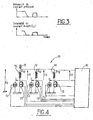
- FIG. 1 represents a circuit diagram of an electric heating radiator 10 belonging more generally to a ventilation, heating and / or air conditioning apparatus (not shown) for a motor vehicle.
- This radiator 10 is constituted by a plurality of heating elements 12, three in this case, electrically mounted in parallel.
- each heating element 12 functions as a positive temperature coefficient (PTC) electrical resistance, that is to say as a resistance whose electrical resistance increases as a function of the heating temperature reached.
- PTC positive temperature coefficient
- Each heating element 12 is electrically connected to a switch 13 connected to the ground and to a current source whose intensity is perfectly known.
- a power tap is provided on the radiator 10 and electrically arranged in a common manner to all the heating elements 12, as shown schematically.
- the voltage of this second current source is known, for example fixed at 12 volts.
- a magnetic torus 20 is disposed around the power plug 15, as is also illustrated in more detail in FIG. 2 which is a sectional view of the power plug 15 and the torus 20.
- An analog processing circuit And a microcontroller 30 are mounted at the output of the magnetic core 20 to recover an induced current created by said core 20, as explained below.
- a heating element 12 which has just been switched on and then off is then powered up again by switching on the corresponding switch 13, still at full power.
- a main current therefore flows through the power supply 15, and the torus 20 being magnetic, this main current creates an induced current I i .
- the induced current I i is recovered and is then filtered and amplified by the analog processing circuit 25.
- the processing circuit 25 makes it possible to measure the current peak I i measured, as illustrated by the bottom diagram of FIG.
- the increase in the measured induced current, i.e. the peak displayed, is a function of the current flowing in the power tap 15.
- the measurement is made for a short period of time so as to obtain an induced current.
- the final value of the measurement gives an image of the current I 12 consumed by said heating element 12, the magnetic field circulating in the torus being a function of the main current.
- the torus 20 is dimensioned so as to be able to measure an intensity I 12 of the current flowing in the heating element 12 corresponding to a minimum temperature of the flow. of air and a maximum air flow through said heating element 12 considered.
- Each heating element 12 which has not been switched on after having been switched off is then successively supplied with power again by switching on the corresponding switch 13, and each induced current I i created by the toroid is measured and then processed.
- the microcontroller 30 adds, after filtering and amplification by the analog processing circuit 25, the intensity I i of all the induced currents created during the supply of each heating element 12, in order to determine the intensity. final I t of the current consumed by the radiator 10 when operating at full load.
- FIG. 4 illustrates a second embodiment of the invention making it possible to measure also the total intensity I t of the current consumed by an electric heater of a ventilation device, heating and / or air conditioning of a motor vehicle.
- the electric heater 10 also has three heating elements 12 connected in parallel. Each heating element 12 is connected to a first current source C1 and a switch 13 which are specific to it. A processing circuit 25 and microcontroller 30 are also provided.
- the method used to measure the current I t consumed by the radiator 10 is as follows:
- the first current source C1 whose intensity I1 is known and whose voltage U1 is accurately measured, flows in one of the heating elements 12 of the radiator 10 by positioning the corresponding switch 13 in the appropriate position.
- the heating element 12 is considered to be a positive temperature coefficient (PTC) resistor, its electrical resistance value changes with increasing temperature. Since the heating elements are most often stacked vertically one above the other in the air stream to form the radiator 10, certain elements, even in the case where they are all structurally identical, do not heat exactly the same way between the top and the bottom of the air vein. The temperature reached in each heating element can thus vary from a few tenths of a degree to a few degrees, thus modifying the value of the electrical resistance R 12 . Thus, it is necessary to measure the electrical resistance accurately for each heating element 12. For this, each heating element is supplied successively by an individual source of current C1. In order to have a precise final measurement, the measurement step of the electrical resistance R12 is thus carried out for each heating element 12.
- PTC positive temperature coefficient
- the heating elements 12 are then preferably all extinguished, although this is not mandatory.
- each heating element 12 is successively supplied with current by switching on the corresponding switch 13 but with a current source whose supply voltage U2 is known (system variable measured continuously).
- This operation is repeated for each heating element 12 in order to know the intensity of the current consumed by each of them.
- the sum of the intensities I 12 is determined by the microcontroller 30 so as to know the total intensity I t of the current consumed by the radiator 10.
Landscapes
- Engineering & Computer Science (AREA)
- Power Engineering (AREA)
- Physics & Mathematics (AREA)
- General Physics & Mathematics (AREA)
- Air-Conditioning For Vehicles (AREA)
- Electric Propulsion And Braking For Vehicles (AREA)
Claims (2)
- Verfahren zur Messung der gesamten Stromstärke It, welcher Strom von einem elektrischen Heizkörper (10) einer Belüftungs-, Heizungs- und/oder Klimaanlage für den Insassenraum eines Automobils verbraucht wird, wobei der besagte Heizkörper aus Heizelementen (12) besteht, die jeweils an einen Schalter (13) angeschlossen sind und einen Magnetkern (20) aufweisen, welcher um eine den Heizelementen (12) gemeinsame Steckdose (15) herum angeordnet ist, dadurch gekennzeichnet, dass- bei Schritt a) ein oder mehrere Heizelemente (12) durch Einschalten des Schalters (13) mit Strom versorgt werden,- bei Schritt b) die Stromversorgung aller in Schritt a) eingeschalteten Heizelemente (12) durch Ausschalten des Schalters (13) unterbrochen wird, um die von dem Magnetkern (20)gespeicherten Energie abzuladen,- bei Schritt c) ein Heizelement (12) erneut durch Einschalten des Schalters (13) mit Strom versorgt wird, die Stromstärke Ii des von dem Magnetkern (20)erzeugten Nebenstroms, wenn er von den Heizelementen (12) verbrauchten Strom durchquert wird, erst gemessen wird, dann gefiltert und verstärkt wird, um in einem Mikrokontroller so verarbeitet zu werden, dass die Stromstärke I12 des von dem Heizelement (12) verbrauchten Stromes gemessen wird,- bei Schritt d) die Schritte a) bis c) mit dem Magnetkern (20) nacheinander wiederholt werden, und dass jedes Heizelement (12), das nach Abschalten nicht wieder eingeschaltet worden ist, nacheinander mit Strom versorgt wird, indem der entsprechende Schalter (13) eingeschaltet wird.- bei Schritt e) die Summe der Stromstärken Ii des Nebenstromes für jedes Heizelement (12) durch einen Mikrokontroller (30) berechnet wird, um die gesamte Stromstärke It des von dem elektrischen Heizkörper (10)verbrauchten Stromes festzustellen.
- Verfahren nach Anspruch 1, dadurch gekennzeichnet, dass ein Luftstrom, der in das Heizelement (12) antrifft, um es zu durchströmen, um dort geheizt zu werden, der Magnetkern (20) so dimensioniert ist, dass er eine in dem Heizelement (12) fließende Stromstärke messen kann, welche einer Mindesttemperatur des Luftflusses und einem maximalen Luftdurchfluss entspricht.
Applications Claiming Priority (3)
| Application Number | Priority Date | Filing Date | Title |
|---|---|---|---|
| FR0302399A FR2851825B1 (fr) | 2003-02-27 | 2003-02-27 | Procede pour mesurer l'intensite du courant consomme par un radiateur electrique d'un appareil de ventilation, de chauffage et/ou de climatisation de vehicule. |
| FR0302399 | 2003-02-27 | ||
| PCT/IB2004/000569 WO2004077077A1 (fr) | 2003-02-27 | 2004-02-24 | Procede pour mesurer l'intensite du courant consomme par un radiateur electrique d'un appareil de ventilation de chauffage et/ou de climatisation de vehicule |
Publications (2)
| Publication Number | Publication Date |
|---|---|
| EP1597597A1 EP1597597A1 (de) | 2005-11-23 |
| EP1597597B1 true EP1597597B1 (de) | 2007-04-25 |
Family
ID=32843030
Family Applications (1)
| Application Number | Title | Priority Date | Filing Date |
|---|---|---|---|
| EP04713954A Expired - Lifetime EP1597597B1 (de) | 2003-02-27 | 2004-02-24 | Verfahren zur messung der stromaufnahme eines elektrischen kühlers in einem fahrzeugbelüftungs-, heiz- oder klimaanlagensystem |
Country Status (6)
| Country | Link |
|---|---|
| EP (1) | EP1597597B1 (de) |
| AT (1) | ATE360824T1 (de) |
| DE (1) | DE602004006087T2 (de) |
| ES (1) | ES2286610T3 (de) |
| FR (1) | FR2851825B1 (de) |
| WO (1) | WO2004077077A1 (de) |
Families Citing this family (2)
| Publication number | Priority date | Publication date | Assignee | Title |
|---|---|---|---|---|
| DE102006053935A1 (de) | 2006-11-15 | 2008-05-29 | Siemens Ag | Anordnung und Verfahren zur Ermittlung von Lastströmen in einem Fahrzeug |
| CN102768127B (zh) * | 2012-08-09 | 2014-11-05 | 上海贝洱热系统有限公司 | 一种用于检测汽车空调的低电压加热器的方法及装置 |
Family Cites Families (4)
| Publication number | Priority date | Publication date | Assignee | Title |
|---|---|---|---|---|
| DE3318270C1 (de) * | 1983-05-19 | 1984-08-02 | Daimler-Benz Ag, 7000 Stuttgart | Strommesssensor zur Funktionskontrolle elektrischer Verbraucher |
| JPH08179002A (ja) * | 1994-12-19 | 1996-07-12 | Nippon Inter Electronics Corp | 半導体素子特性測定装置 |
| DE10061458B4 (de) * | 2000-12-09 | 2005-12-15 | Eichenauer Heizelemente Gmbh & Co. Kg | Verfahren und Vorrichtung zum Regeln einer Kfz-Zusatzheizung |
| US6479976B1 (en) * | 2001-06-28 | 2002-11-12 | Thomas G. Edel | Method and apparatus for accurate measurement of pulsed electric currents utilizing ordinary current transformers |
-
2003
- 2003-02-27 FR FR0302399A patent/FR2851825B1/fr not_active Expired - Lifetime
-
2004
- 2004-02-24 AT AT04713954T patent/ATE360824T1/de not_active IP Right Cessation
- 2004-02-24 DE DE602004006087T patent/DE602004006087T2/de not_active Expired - Lifetime
- 2004-02-24 EP EP04713954A patent/EP1597597B1/de not_active Expired - Lifetime
- 2004-02-24 WO PCT/IB2004/000569 patent/WO2004077077A1/fr not_active Ceased
- 2004-02-24 ES ES04713954T patent/ES2286610T3/es not_active Expired - Lifetime
Also Published As
| Publication number | Publication date |
|---|---|
| EP1597597A1 (de) | 2005-11-23 |
| DE602004006087D1 (de) | 2007-06-06 |
| DE602004006087T2 (de) | 2007-12-27 |
| WO2004077077A1 (fr) | 2004-09-10 |
| FR2851825A1 (fr) | 2004-09-03 |
| ATE360824T1 (de) | 2007-05-15 |
| ES2286610T3 (es) | 2007-12-01 |
| FR2851825B1 (fr) | 2005-04-15 |
Similar Documents
| Publication | Publication Date | Title |
|---|---|---|
| EP0892273B1 (de) | Versorgungsschaltung für einen Elektizitätszähler | |
| EP0567402B1 (de) | Vorrichtung für die Heizung und Lüftung des Innenraums von Motorfahrzeugen mit geringer Wärmeabgabe des Motors | |
| WO2018115032A1 (fr) | Capteur de courant a vanne de flux | |
| EP0782265B1 (de) | Verfahren und Vorrichtung zum Schutz eines einstellbaren Impedanzelements zur Steuerung der Stromversorgung eines Elektromotors, insbesondere eines Kraftfahrzeugs | |
| EP1597597B1 (de) | Verfahren zur messung der stromaufnahme eines elektrischen kühlers in einem fahrzeugbelüftungs-, heiz- oder klimaanlagensystem | |
| FR2920884A1 (fr) | Procede d'estimation de l'etat de sante d'une batterie embarquee dans un vehicule automobile. | |
| EP1217707B1 (de) | Verfahren zur Bestimmung eines Primärstroms für Stromwandler mit Sättigungskorrekturmitteln | |
| FR2495687A1 (fr) | Circuit de securite pour dispositif de regulation de la temperature d'un fluide de refroidissement d'un moteur a combustion interne | |
| FR2855260A1 (fr) | Element de mesure pour un capteur de passage notamment un debitmetre massique d'air equipant un moteur a combustion interne | |
| EP3877772B1 (de) | Verfahren zur erkennung einer überhitzung einer heizvorrichtung und entsprechende steuereinheit | |
| EP4350925B1 (de) | Überwachung und optimierung des stromverbrauchs | |
| EP1943725B1 (de) | Messung eines von einer elektrischen drehmaschine wie ein generator gelieferten stroms | |
| EP1469197B1 (de) | Verfahren zur Steuerung des Primärstroms eines Zündsystems einer fremdgezündeten Brennkraftmaschine | |
| FR3006056A1 (fr) | Procede de mesure de forts courants electriques par effet magnetique et dispositif de mesure correspondant | |
| FR2855261A1 (fr) | Capteur de passage a deux resistances | |
| EP2396665B1 (de) | Verfahren zum detektieren eines kurzschlusses und stromversorgungsmodul zum durchführen des verfahrens | |
| EP0074297A1 (de) | Hybrider kompensierter Stromwandler | |
| FR2500927A1 (fr) | Disposilif de mesure du debit d'un fluide | |
| EP4038468B1 (de) | Thermisches management-prozess, insbesondere für ein kraftfahrzeug und zugehörige steuereinheit | |
| EP1580887A1 (de) | Geschwindigkeitsregelanlage eines Motor eines Lüftermotoreinheit, inbesondres für eine Heizungs- und Klimaanlage eines Fahrzeuges | |
| FR2878316A1 (fr) | Dispositif de chauffage electrique, notamment pour appareil de chauffage, de ventilation et/ou de climatisation de vehicule | |
| FR2838891A1 (fr) | Circuit electronique de controle et de limitation d'un courant electrique dans une charge soumise a une tension d'alimentation | |
| EP0610148A1 (de) | Temperaturmessung beim Schweissen oder Pressen | |
| WO2018083405A1 (fr) | Procede de controle d'un alternateur de machine electrique rotative | |
| FR2868844A1 (fr) | Dispositif de mesure d'un courant continu et dispositif de controle du fonctionnement d'une batterie de vehicule automobile |
Legal Events
| Date | Code | Title | Description |
|---|---|---|---|
| PUAI | Public reference made under article 153(3) epc to a published international application that has entered the european phase |
Free format text: ORIGINAL CODE: 0009012 |
|
| 17P | Request for examination filed |
Effective date: 20050824 |
|
| AK | Designated contracting states |
Kind code of ref document: A1 Designated state(s): AT BE BG CH CY CZ DE DK EE ES FI FR GB GR HU IE IT LI LU MC NL PT RO SE SI SK TR |
|
| AX | Request for extension of the european patent |
Extension state: AL LT LV MK |
|
| DAX | Request for extension of the european patent (deleted) | ||
| 17Q | First examination report despatched |
Effective date: 20051124 |
|
| GRAP | Despatch of communication of intention to grant a patent |
Free format text: ORIGINAL CODE: EPIDOSNIGR1 |
|
| GRAS | Grant fee paid |
Free format text: ORIGINAL CODE: EPIDOSNIGR3 |
|
| GRAA | (expected) grant |
Free format text: ORIGINAL CODE: 0009210 |
|
| AK | Designated contracting states |
Kind code of ref document: B1 Designated state(s): AT BE BG CH CY CZ DE DK EE ES FI FR GB GR HU IE IT LI LU MC NL PT RO SE SI SK TR |
|
| PG25 | Lapsed in a contracting state [announced via postgrant information from national office to epo] |
Ref country code: FI Free format text: LAPSE BECAUSE OF FAILURE TO SUBMIT A TRANSLATION OF THE DESCRIPTION OR TO PAY THE FEE WITHIN THE PRESCRIBED TIME-LIMIT Effective date: 20070425 |
|
| REG | Reference to a national code |
Ref country code: GB Ref legal event code: FG4D Free format text: NOT ENGLISH |
|
| REG | Reference to a national code |
Ref country code: IE Ref legal event code: FG4D Free format text: LANGUAGE OF EP DOCUMENT: FRENCH |
|
| REG | Reference to a national code |
Ref country code: CH Ref legal event code: EP |
|
| REF | Corresponds to: |
Ref document number: 602004006087 Country of ref document: DE Date of ref document: 20070606 Kind code of ref document: P |
|
| PG25 | Lapsed in a contracting state [announced via postgrant information from national office to epo] |
Ref country code: SE Free format text: LAPSE BECAUSE OF FAILURE TO SUBMIT A TRANSLATION OF THE DESCRIPTION OR TO PAY THE FEE WITHIN THE PRESCRIBED TIME-LIMIT Effective date: 20070725 |
|
| PG25 | Lapsed in a contracting state [announced via postgrant information from national office to epo] |
Ref country code: PT Free format text: LAPSE BECAUSE OF FAILURE TO SUBMIT A TRANSLATION OF THE DESCRIPTION OR TO PAY THE FEE WITHIN THE PRESCRIBED TIME-LIMIT Effective date: 20070925 |
|
| NLV1 | Nl: lapsed or annulled due to failure to fulfill the requirements of art. 29p and 29m of the patents act | ||
| GBV | Gb: ep patent (uk) treated as always having been void in accordance with gb section 77(7)/1977 [no translation filed] |
Effective date: 20070425 |
|
| PG25 | Lapsed in a contracting state [announced via postgrant information from national office to epo] |
Ref country code: AT Free format text: LAPSE BECAUSE OF FAILURE TO SUBMIT A TRANSLATION OF THE DESCRIPTION OR TO PAY THE FEE WITHIN THE PRESCRIBED TIME-LIMIT Effective date: 20070425 |
|
| REG | Reference to a national code |
Ref country code: IE Ref legal event code: FD4D |
|
| REG | Reference to a national code |
Ref country code: ES Ref legal event code: FG2A Ref document number: 2286610 Country of ref document: ES Kind code of ref document: T3 |
|
| PG25 | Lapsed in a contracting state [announced via postgrant information from national office to epo] |
Ref country code: SI Free format text: LAPSE BECAUSE OF FAILURE TO SUBMIT A TRANSLATION OF THE DESCRIPTION OR TO PAY THE FEE WITHIN THE PRESCRIBED TIME-LIMIT Effective date: 20070425 Ref country code: NL Free format text: LAPSE BECAUSE OF FAILURE TO SUBMIT A TRANSLATION OF THE DESCRIPTION OR TO PAY THE FEE WITHIN THE PRESCRIBED TIME-LIMIT Effective date: 20070425 Ref country code: IE Free format text: LAPSE BECAUSE OF FAILURE TO SUBMIT A TRANSLATION OF THE DESCRIPTION OR TO PAY THE FEE WITHIN THE PRESCRIBED TIME-LIMIT Effective date: 20070425 Ref country code: DK Free format text: LAPSE BECAUSE OF FAILURE TO SUBMIT A TRANSLATION OF THE DESCRIPTION OR TO PAY THE FEE WITHIN THE PRESCRIBED TIME-LIMIT Effective date: 20070425 Ref country code: BG Free format text: LAPSE BECAUSE OF FAILURE TO SUBMIT A TRANSLATION OF THE DESCRIPTION OR TO PAY THE FEE WITHIN THE PRESCRIBED TIME-LIMIT Effective date: 20070725 |
|
| PG25 | Lapsed in a contracting state [announced via postgrant information from national office to epo] |
Ref country code: SK Free format text: LAPSE BECAUSE OF FAILURE TO SUBMIT A TRANSLATION OF THE DESCRIPTION OR TO PAY THE FEE WITHIN THE PRESCRIBED TIME-LIMIT Effective date: 20070425 |
|
| PLBE | No opposition filed within time limit |
Free format text: ORIGINAL CODE: 0009261 |
|
| STAA | Information on the status of an ep patent application or granted ep patent |
Free format text: STATUS: NO OPPOSITION FILED WITHIN TIME LIMIT |
|
| 26N | No opposition filed |
Effective date: 20080128 |
|
| PG25 | Lapsed in a contracting state [announced via postgrant information from national office to epo] |
Ref country code: GB Free format text: LAPSE BECAUSE OF FAILURE TO SUBMIT A TRANSLATION OF THE DESCRIPTION OR TO PAY THE FEE WITHIN THE PRESCRIBED TIME-LIMIT Effective date: 20070425 Ref country code: GR Free format text: LAPSE BECAUSE OF FAILURE TO SUBMIT A TRANSLATION OF THE DESCRIPTION OR TO PAY THE FEE WITHIN THE PRESCRIBED TIME-LIMIT Effective date: 20070726 |
|
| PG25 | Lapsed in a contracting state [announced via postgrant information from national office to epo] |
Ref country code: RO Free format text: LAPSE BECAUSE OF FAILURE TO SUBMIT A TRANSLATION OF THE DESCRIPTION OR TO PAY THE FEE WITHIN THE PRESCRIBED TIME-LIMIT Effective date: 20070425 |
|
| BERE | Be: lapsed |
Owner name: VALEO SYSTEMES THERMIQUES Effective date: 20080228 |
|
| REG | Reference to a national code |
Ref country code: CH Ref legal event code: PL |
|
| PG25 | Lapsed in a contracting state [announced via postgrant information from national office to epo] |
Ref country code: LI Free format text: LAPSE BECAUSE OF NON-PAYMENT OF DUE FEES Effective date: 20080229 Ref country code: MC Free format text: LAPSE BECAUSE OF NON-PAYMENT OF DUE FEES Effective date: 20080228 Ref country code: CH Free format text: LAPSE BECAUSE OF NON-PAYMENT OF DUE FEES Effective date: 20080229 |
|
| PG25 | Lapsed in a contracting state [announced via postgrant information from national office to epo] |
Ref country code: EE Free format text: LAPSE BECAUSE OF FAILURE TO SUBMIT A TRANSLATION OF THE DESCRIPTION OR TO PAY THE FEE WITHIN THE PRESCRIBED TIME-LIMIT Effective date: 20070425 |
|
| PG25 | Lapsed in a contracting state [announced via postgrant information from national office to epo] |
Ref country code: BE Free format text: LAPSE BECAUSE OF NON-PAYMENT OF DUE FEES Effective date: 20080228 |
|
| PG25 | Lapsed in a contracting state [announced via postgrant information from national office to epo] |
Ref country code: CY Free format text: LAPSE BECAUSE OF FAILURE TO SUBMIT A TRANSLATION OF THE DESCRIPTION OR TO PAY THE FEE WITHIN THE PRESCRIBED TIME-LIMIT Effective date: 20070425 |
|
| PG25 | Lapsed in a contracting state [announced via postgrant information from national office to epo] |
Ref country code: LU Free format text: LAPSE BECAUSE OF NON-PAYMENT OF DUE FEES Effective date: 20080224 Ref country code: HU Free format text: LAPSE BECAUSE OF FAILURE TO SUBMIT A TRANSLATION OF THE DESCRIPTION OR TO PAY THE FEE WITHIN THE PRESCRIBED TIME-LIMIT Effective date: 20071026 |
|
| PG25 | Lapsed in a contracting state [announced via postgrant information from national office to epo] |
Ref country code: TR Free format text: LAPSE BECAUSE OF FAILURE TO SUBMIT A TRANSLATION OF THE DESCRIPTION OR TO PAY THE FEE WITHIN THE PRESCRIBED TIME-LIMIT Effective date: 20070425 |
|
| REG | Reference to a national code |
Ref country code: FR Ref legal event code: PLFP Year of fee payment: 13 |
|
| REG | Reference to a national code |
Ref country code: FR Ref legal event code: PLFP Year of fee payment: 14 |
|
| PGFP | Annual fee paid to national office [announced via postgrant information from national office to epo] |
Ref country code: IT Payment date: 20170217 Year of fee payment: 14 Ref country code: ES Payment date: 20170228 Year of fee payment: 14 |
|
| REG | Reference to a national code |
Ref country code: FR Ref legal event code: PLFP Year of fee payment: 15 |
|
| PG25 | Lapsed in a contracting state [announced via postgrant information from national office to epo] |
Ref country code: IT Free format text: LAPSE BECAUSE OF NON-PAYMENT OF DUE FEES Effective date: 20180224 |
|
| REG | Reference to a national code |
Ref country code: ES Ref legal event code: FD2A Effective date: 20190801 |
|
| PG25 | Lapsed in a contracting state [announced via postgrant information from national office to epo] |
Ref country code: ES Free format text: LAPSE BECAUSE OF NON-PAYMENT OF DUE FEES Effective date: 20180225 |
|
| PGFP | Annual fee paid to national office [announced via postgrant information from national office to epo] |
Ref country code: CZ Payment date: 20220121 Year of fee payment: 19 |
|
| PGFP | Annual fee paid to national office [announced via postgrant information from national office to epo] |
Ref country code: FR Payment date: 20230227 Year of fee payment: 20 |
|
| PGFP | Annual fee paid to national office [announced via postgrant information from national office to epo] |
Ref country code: DE Payment date: 20230207 Year of fee payment: 20 |
|
| P01 | Opt-out of the competence of the unified patent court (upc) registered |
Effective date: 20230528 |
|
| PG25 | Lapsed in a contracting state [announced via postgrant information from national office to epo] |
Ref country code: CZ Free format text: LAPSE BECAUSE OF NON-PAYMENT OF DUE FEES Effective date: 20230224 |
|
| REG | Reference to a national code |
Ref country code: DE Ref legal event code: R071 Ref document number: 602004006087 Country of ref document: DE |