EP1597597B1 - Procede pour mesurer l'intensite du courant consomme par un radiateur electrique d'un appareil de ventilation de chauffa ge et/ou de climatisation de vehicule - Google Patents
Procede pour mesurer l'intensite du courant consomme par un radiateur electrique d'un appareil de ventilation de chauffa ge et/ou de climatisation de vehicule Download PDFInfo
- Publication number
- EP1597597B1 EP1597597B1 EP04713954A EP04713954A EP1597597B1 EP 1597597 B1 EP1597597 B1 EP 1597597B1 EP 04713954 A EP04713954 A EP 04713954A EP 04713954 A EP04713954 A EP 04713954A EP 1597597 B1 EP1597597 B1 EP 1597597B1
- Authority
- EP
- European Patent Office
- Prior art keywords
- current
- heating element
- heating
- intensity
- switch
- Prior art date
- Legal status (The legal status is an assumption and is not a legal conclusion. Google has not performed a legal analysis and makes no representation as to the accuracy of the status listed.)
- Expired - Lifetime
Links
Images

Classifications
-
- G—PHYSICS
- G01—MEASURING; TESTING
- G01R—MEASURING ELECTRIC VARIABLES; MEASURING MAGNETIC VARIABLES
- G01R15/00—Details of measuring arrangements of the types provided for in groups G01R17/00 - G01R29/00, G01R33/00 - G01R33/26 or G01R35/00
- G01R15/14—Adaptations providing voltage or current isolation, e.g. for high-voltage or high-current networks
- G01R15/18—Adaptations providing voltage or current isolation, e.g. for high-voltage or high-current networks using inductive devices, e.g. transformers
- G01R15/183—Adaptations providing voltage or current isolation, e.g. for high-voltage or high-current networks using inductive devices, e.g. transformers using transformers with a magnetic core
-
- G—PHYSICS
- G01—MEASURING; TESTING
- G01R—MEASURING ELECTRIC VARIABLES; MEASURING MAGNETIC VARIABLES
- G01R19/00—Arrangements for measuring currents or voltages or for indicating presence or sign thereof
- G01R19/0092—Measuring current only
-
- G—PHYSICS
- G01—MEASURING; TESTING
- G01R—MEASURING ELECTRIC VARIABLES; MEASURING MAGNETIC VARIABLES
- G01R31/00—Arrangements for testing electric properties; Arrangements for locating electric faults; Arrangements for electrical testing characterised by what is being tested not provided for elsewhere
- G01R31/005—Testing of electric installations on transport means
- G01R31/006—Testing of electric installations on transport means on road vehicles, e.g. automobiles or trucks
- G01R31/007—Testing of electric installations on transport means on road vehicles, e.g. automobiles or trucks using microprocessors or computers
Definitions
- the invention relates to a method for measuring the intensity of the current consumed by an electric heater of a ventilation device, heating and / or air conditioning vehicle.
- certain electrical components for heating, ventilation and / or air conditioning apparatus of a passenger compartment of a motor vehicle such as electric radiators
- means for measuring consumption of the current used by each of their heating elements also called phases.
- These means are particularly useful for managing the energy of the vehicle. The accuracy of the measurement is therefore important to provide feedback that is representative of the operation of the radiator.
- DE 100 61 458 or the use of a transistor which includes in its functionalities the possibility of directly indicating the intensity of the current flowing through it, and therefore the current consumed by the radiator.
- the transistor is either placed in the air flow, close to the heating elements, or outside the air flow, for example close to a control circuit of the radiator. It is also possible to use a measurement element added directly to the power source. In both cases, a microcontroller is used to sum the consumption of each heating element in order to deduce the total consumption of the radiator current.
- the invention proposes to integrate a sensor in the electric heater non-intrusively, without placing said sensor in series with the current that is measured, and therefore without power dissipation or loss of current.
- the measurement of the electrical quantity is a measure of the intensity of the current consumed by the heating element made by placing a magnetic toroid around the socket. supplying said heating element, and measuring the intensity of the induced current created by said toroid when it is traversed by the current consumed by the heating element.
- a stream of air arriving in the heating element to cross it in order to be heated, the torus is dimensioned so as to measure an intensity of the current flowing in the heating element corresponding to a minimum temperature of the flow of water. air and maximum airflow.
- step d) the element (s) lit (s) in step c) remains (s) lit (s) during the ignition of another element.
- FIG. 1 represents a circuit diagram of an electric heating radiator 10 belonging more generally to a ventilation, heating and / or air conditioning apparatus (not shown) for a motor vehicle.
- This radiator 10 is constituted by a plurality of heating elements 12, three in this case, electrically mounted in parallel.
- each heating element 12 functions as a positive temperature coefficient (PTC) electrical resistance, that is to say as a resistance whose electrical resistance increases as a function of the heating temperature reached.
- PTC positive temperature coefficient
- Each heating element 12 is electrically connected to a switch 13 connected to the ground and to a current source whose intensity is perfectly known.
- a power tap is provided on the radiator 10 and electrically arranged in a common manner to all the heating elements 12, as shown schematically.
- the voltage of this second current source is known, for example fixed at 12 volts.
- a magnetic torus 20 is disposed around the power plug 15, as is also illustrated in more detail in FIG. 2 which is a sectional view of the power plug 15 and the torus 20.
- An analog processing circuit And a microcontroller 30 are mounted at the output of the magnetic core 20 to recover an induced current created by said core 20, as explained below.
- a heating element 12 which has just been switched on and then off is then powered up again by switching on the corresponding switch 13, still at full power.
- a main current therefore flows through the power supply 15, and the torus 20 being magnetic, this main current creates an induced current I i .
- the induced current I i is recovered and is then filtered and amplified by the analog processing circuit 25.
- the processing circuit 25 makes it possible to measure the current peak I i measured, as illustrated by the bottom diagram of FIG.
- the increase in the measured induced current, i.e. the peak displayed, is a function of the current flowing in the power tap 15.
- the measurement is made for a short period of time so as to obtain an induced current.
- the final value of the measurement gives an image of the current I 12 consumed by said heating element 12, the magnetic field circulating in the torus being a function of the main current.
- the torus 20 is dimensioned so as to be able to measure an intensity I 12 of the current flowing in the heating element 12 corresponding to a minimum temperature of the flow. of air and a maximum air flow through said heating element 12 considered.
- Each heating element 12 which has not been switched on after having been switched off is then successively supplied with power again by switching on the corresponding switch 13, and each induced current I i created by the toroid is measured and then processed.
- the microcontroller 30 adds, after filtering and amplification by the analog processing circuit 25, the intensity I i of all the induced currents created during the supply of each heating element 12, in order to determine the intensity. final I t of the current consumed by the radiator 10 when operating at full load.
- FIG. 4 illustrates a second embodiment of the invention making it possible to measure also the total intensity I t of the current consumed by an electric heater of a ventilation device, heating and / or air conditioning of a motor vehicle.
- the electric heater 10 also has three heating elements 12 connected in parallel. Each heating element 12 is connected to a first current source C1 and a switch 13 which are specific to it. A processing circuit 25 and microcontroller 30 are also provided.
- the method used to measure the current I t consumed by the radiator 10 is as follows:
- the first current source C1 whose intensity I1 is known and whose voltage U1 is accurately measured, flows in one of the heating elements 12 of the radiator 10 by positioning the corresponding switch 13 in the appropriate position.
- the heating element 12 is considered to be a positive temperature coefficient (PTC) resistor, its electrical resistance value changes with increasing temperature. Since the heating elements are most often stacked vertically one above the other in the air stream to form the radiator 10, certain elements, even in the case where they are all structurally identical, do not heat exactly the same way between the top and the bottom of the air vein. The temperature reached in each heating element can thus vary from a few tenths of a degree to a few degrees, thus modifying the value of the electrical resistance R 12 . Thus, it is necessary to measure the electrical resistance accurately for each heating element 12. For this, each heating element is supplied successively by an individual source of current C1. In order to have a precise final measurement, the measurement step of the electrical resistance R12 is thus carried out for each heating element 12.
- PTC positive temperature coefficient
- the heating elements 12 are then preferably all extinguished, although this is not mandatory.
- each heating element 12 is successively supplied with current by switching on the corresponding switch 13 but with a current source whose supply voltage U2 is known (system variable measured continuously).
- This operation is repeated for each heating element 12 in order to know the intensity of the current consumed by each of them.
- the sum of the intensities I 12 is determined by the microcontroller 30 so as to know the total intensity I t of the current consumed by the radiator 10.
Landscapes
- Engineering & Computer Science (AREA)
- Power Engineering (AREA)
- Physics & Mathematics (AREA)
- General Physics & Mathematics (AREA)
- Air-Conditioning For Vehicles (AREA)
- Electric Propulsion And Braking For Vehicles (AREA)
Description
- L'invention se rapporte à un procédé pour mesurer l'intensité du courant consommé par un radiateur électrique d'un appareil de ventilation, de chauffage et/ou de climatisation de véhicule.
- Actuellement, certains organes électriques de chauffage pour appareil de ventilation, de chauffage et/ou de climatisation d'habitacle de véhicule automobile, tel que des radiateurs électriques, sont pourvus de moyens de mesure de consommation du courant utilisé par chacun de leurs éléments chauffants, appelés également phases. Ces moyens sont notamment utiles pour la gestion de l'énergie du véhicule. La précision de la mesure est donc importante pour fournir une information en retour qui est représentative du fonctionnement du radiateur.
- Parmi les techniques utilisées, on peut citer le document DE 100 61 458 ou l'utilisation d'un transistor qui inclut dans ses fonctionnalités la possibilité d'indiquer directement l'intensité du courant qui le traverse, et donc le courant consommé par le radiateur. Le transistor est soit placé dans le flux d'air, proche des éléments chauffants, soit en dehors du flux d'air, par exemple proche d'un circuit de commande du radiateur. Il est également possible d'utiliser un élément de mesure ajouté directement à la source de courant. Dans ces deux cas, un micro-contrôleur est utilisé pour sommer la consommation de chaque élément chauffant afin de déduire la consommation totale du courant du radiateur.
- Cependant, ces techniques présentent des limitations et des inconvénients. D'abord, la précision des mesures est faible, à moins de prévoir une phase d'étalonnage au moment de la fabrication du produit, celui-ci ne fournissant pas, généralement, de résultats suffisamment fiables dans le temps. Le coût est également prohibitif dans certains cas, notamment par l'utilisation d'un transistor incluant dans ses fonctionnalités la possibilité d'indiquer directement l'intensité.
- Pour résoudre ces problèmes, l'invention propose d'intégrer un capteur dans l'organe de chauffage électrique de manière non intrusive, sans placer ledit capteur en série avec le courant qui est mesuré, et donc sans dissipation de puissance ni perte de courant.
- Plus précisément, l'invention se rapporte à un procédé pour mesurer l'intensité totale du courant consommé par au moins un élément chauffant d'un radiateur électrique d'un appareil de ventilation, de chauffage et/ou de climatisation pour habitacle de véhicule automobile, caractérisé en ce qu'il comprend les étapes suivantes :
- a) alimenter en courant ledit au moins élément chauffant pour le faire fonctionner au maximum de sa puissance en allumant un interrupteur,
- b) couper l'alimentation électrique dudit au moins un élément chauffant mis en route à l'étape a) en éteignant l'interrupteur,
- c) alimenter électriquement de nouveau ledit au moins un élément chauffant et mesurer une grandeur physique électrique dudit élément chauffant liée directement ou indirectement à l'intensité totale du courant consommé par cet élément chauffant.
- Selon un premier mode de réalisation de l'invention, à l'étape c), la mesure de la grandeur électrique est une mesure de l'intensité du courant consommé par l'élément chauffant réalisée en plaçant un tore magnétique autour de la prise d'alimentation dudit élément chauffant, et en mesurant l'intensité du courant induit créé par ledit tore lorsqu'il est traversé par le courant consommé par l'élément chauffant.
- Avantageusement, un flux d'air arrivant dans l'élément chauffant pour le traverser afin d'y être réchauffé, le tore est dimensionné de manière à pouvoir mesurer une intensité du courant circulant dans l'élément chauffant correspondant à une température minimale du flux d'air et un débit d'air maximal.
- De préférence, :
- à l'étape a), les éléments chauffants sont alimentés successivement en courant en allumant l'interrupteur,
- à l'étape b), l'alimentation électrique de tous les éléments chauffants allumés à l'étape a) est coupée en éteignant l'interrupteur, pour décharger l'énergie stockée par le tore,
- à l'étape c), chaque élément chauffant est alimenté de nouveau en courant en allumant l'interrupteur, et l'intensité du courant induit créé par le tore est mesurée puis filtrée et amplifiée afin d'être traitée dans un micro-contrôleur,
- à l'étape d), les étapes a) à c) sont réitérées successivement avec le même tore placé à une entrée commune de tous les éléments chauffants, et
- à l'étape e), la somme des intensités du courant induit créé par le tore pour chaque élément chauffant est calculée par le micro-contrôleur pour déterminer l'intensité totale du courant consommé par le radiateur électrique.
- Selon un autre mode de réalisation de l'invention :
- à l'étape a), des éléments chauffants du radiateur électrique sont alimentés à l'aide d'une source de courant dédiée individuellement à chaque élément chauffant et dont l'intensité est connue et la tension est mesurée en continue, de manière à déterminer la résistance électrique de chaque élément chauffant, à l'aide de la relation du type U=R x I,
- à l'étape b), l'alimentation d'au moins un élément chauffant est coupée,
- à l'étape c), ledit au moins un élément chauffant coupé à l'étape b) est de nouveau alimenté à l'aide de la source, et l'intensité du courant consommé par chaque élément chauffant est calculé à l'aide de la relation du type U=R x I,
- à l'étape d), on réitère les étapes a) à c) successivement pour tous les éléments chauffants est successivement alimenté, à l'étape c), et
- à l'étape e), la somme des intensités calculées est effectuée afin d'obtenir l'intensité totale du courant consommé par le radiateur électrique.
- Avantageusement, à l'étape d), le ou les élément(s) allumés(s) à l'étape c) reste(nt) allumé(s) lors de l'allumage d'un autre élément.
- D'autres caractéristiques, détails et avantages de l'invention ressortiront à la lecture de la description faite en référence aux dessins annexés donnés à titre d'exemple qui représentent respectivement :
- la figure 1, une vue schématique d'un radiateur électrique de chauffage pour appareil de ventilation, de chauffage et/ou de ventilation d'habitacle de véhicule automobile selon la présente invention,
- la figure 2, une vue en coupe du câble d'alimentation du radiateur,
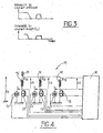
- la figure 3, une vue schématique représentant l'intensité du courant circulant dans un tore magnétique monté autour d'une prise d'alimentation du radiateur et faisant office de capteur de mesure,
- la figure 4, une vue schématique d'un deuxième mode de réalisation d'un radiateur électrique conforme à l'invention,
- La figure 1 représente un schéma électrique d'un radiateur électrique de chauffage 10 appartenant de manière plus globale à un appareil de ventilation, de chauffage et/ou de climatisation (non représenté) pour véhicule automobile.
- Ce radiateur 10 est constitué par une pluralité d'éléments de chauffage 12, trois dans le cas présent, montés électriquement en parallèles. Typiquement, chaque élément chauffant 12 fonctionne comme une résistance électrique à coefficient de température positif (CTP), c'est-à-dire comme une résistance dont la résistance électrique augmente en fonction de la température de chauffage atteinte. Chaque élément chauffant 12 est relié électriquement à un interrupteur 13 relié à la masse et à une source de courant dont l'intensité est parfaitement connue. Une prise 15 d'alimentation est prévue sur le radiateur 10 et agencée électriquement de manière commune à tous les éléments chauffants 12, comme cela est schématisé. La tension de cette deuxième source de courant est connue, par exemple fixée à 12 Volts. Un tore magnétique 20 est disposé autour de la prise d'alimentation 15, comme cela est également illustré plus en détail sur la figure 2 qui est une vue en coupe de la prise d'alimentation 15 et du tore 20. Un circuit de traitement analogique 25 et un micro-contrôleur 30 sont montés en sortie du tore magnétique 20 pour récupérer un courant induit créé par ledit tore 20, comme cela est expliqué ci-après.
- Le procédé utilisé pour déterminer le courant total It consommé par le radiateur électrique 10, c'est-à-dire le courant consommé par tous ses éléments chauffants 12 alimentés en pleine charge, est le suivant :
- Dans un premier temps, au moins un élément chauffant 12 est mis en route à pleine puissance en allumant l'interrupteur 13 correspondant. Comme cela est indiqué sur la figure 3, la courbe du haut illustre l'application du premier courant à l'élément chauffant.
- Ensuite, tous les éléments chauffants allumés à l'étape précédente sont éteints en éteignant l'interrupteur 13 afin de décharger le tore 20 en énergie, comme illustré par les traits en pointillés du schéma du bas de la figure 3.
- Un élément chauffant 12 venant d'être allumé puis éteint est alors alimenté de nouveau en courant en allumant l'interrupteur 13 correspondant, toujours à pleine puissance.
- Un courant principal circule donc au travers de la prise d'alimentation 15, et le tore 20 étant magnétique, ce courant principal créé un courant Ii induit. Le courant induit Ii est récupéré puis est filtré et amplifié par le circuit de traitement analogique 25. En particulier, le circuit de traitement 25 permet de mesurer le pic de courant Ii mesuré, comme illustré par le schéma du bas de la figure 3. L'augmentation du courant induit mesuré, c'est-à-dire le pic affiché, est fonction du courant circulant dans la prise d'alimentation 15. La mesure est effectuée pendant un court intervalle de temps de manière à obtenir un courant induit, la valeur finale de la mesure donne une image du courant I12 consommé par ledit élément chauffant 12, le champ magnétique circulant dans le tore étant fonction du courant principal. Si l'amplitude du champ magnétique monte trop haut, le tore 20 peut saturer, ce qui conduit à une mesure invalide. C'est la raison pour laquelle pendant la mesure, le courant doit être limité, par exemple à 30 A. cette limitation de courant peut cependant être augmentée en augmentant la taille du tore pour éviter la saturation. En pratique, comme il est préférable de réduire les dimensions du tore pour des questions d'encombrement, le tore 20 est dimensionné de manière à pouvoir mesurer une intensité I12 du courant circulant dans l'élément chauffant 12 correspondant à une température minimale du flux d'air et un débit d'air maximal traversant ledit élément chauffant 12 considéré.
- Chaque élément chauffant 12 qui n'a pas été allumé après avoir été éteint est ensuite successivement alimenté de nouveau en courant en allumant l'interrupteur 13 correspondant, et chaque courant induit Ii créé par le tore est mesuré, puis traité.
- Au final, le micro-contrôleur 30 additionne, après filtrage et amplification par le circuit de traitement analogique 25, l'intensité Ii de tous les courants induits créés lors de l'alimentation de chaque élément chauffant 12, afin de déterminer l'intensité finale It du courant consommé par le radiateur 10 lorsqu'il fonctionne à pleine charge.
- La figure 4 illustre un deuxième mode de réalisation de l'invention permettant de mesurer également l'intensité totale It du courant consommé par un radiateur électrique d'un appareil de ventilation, de chauffage et/ou de climatisation de véhicule automobile.
- Le radiateur électrique 10 comporte également trois éléments chauffants 12 montés en parallèle. Chaque élément chauffant 12 est relié à une première source de courant C1 et un interrupteur 13 qui lui sont propres. Un circuit de traitement 25 et micro-contrôleur 30 sont également prévus.
- Le procédé utilisé pour mesuré le courant It consommé par le radiateur 10 est le suivant :
- La première source de courant C1, dont l'intensité I1 est connue et dont la tension U1 est mesurée avec précision, circule dans un des éléments chauffants 12 du radiateur 10 en positionnant l'interrupteur 13 correspondant dans la position appropriée. La résistance électrique R12 de l'élément chauffant 12 est alors déterminée à l'aide de la relation U1=R12 x I1.
- L'élément chauffant 12 étant considéré comme une résistance à coefficient de température positif (CTP), sa valeur de résistance électrique évolue en augmentant avec la température. Comme les éléments chauffants sont le plus souvent empilés verticalement les uns au-dessus des autres dans la veine d'air pour former le radiateur 10, certains éléments, même dans le cas où ils sont tous strictement identiques structurellement parlant, ne chauffent pas exactement de la même façon entre le haut et le bas de la veine d'air. La température atteinte dans chaque élément chauffant peut ainsi varier de quelques dixièmes de degré à quelques degrés, modifiant ainsi la valeur de la résistance électrique R12. Ainsi, il convient de mesure la résistance électrique de manière précise pour chaque élément chauffant 12. Pour cela, chaque élément chauffant est alimenté successivement par une source individuelle de courant C1. Afin d'avoir une mesure finale précise, l'étape de mesure de la résistance électrique R12 est donc effectuée pour chaque élément chauffant 12.
- Une fois la valeur de la résistance électrique R12 de chaque élément chauffant 12 obtenue, les éléments chauffants 12 sont alors de préférence tous éteints, bien que cela ne soit pas obligatoire.
- Ensuite, chaque élément chauffant 12 est successivement alimenté de nouveau en courant en allumant l'interrupteur 13 correspondant mais avec une source de courant dont la tension d'alimentation U2 est connue (variable du système mesurée en permanence). En utilisant la relation U2=R12 x I12, il est ainsi possible de calculer l'intensité I12 du courant qui circule dans l'élément chauffant 12 et correspond au courant consommé par ledit élément chauffant, à l'aide de la formule suivante :

- Cette opération est réitérée pour chaque élément chauffant 12 afin de connaître l'intensité du courant consommé par chacun d'entre eux.
- Enfin, la somme des intensités I12 est déterminée par le micro-contrôleur 30 de manière à connaître l'intensité totale It du courant consommé par le radiateur 10.
- Il est intéressant de noter qu'il y a différentes variantes de réalisation concernant ce mode de fonctionnement. En effet, il est possible d'allumer tous les éléments chauffants dans la première étape, d'en éteindre seulement un certain nombre dans la seconde étape, par exemple deux sur trois, et d'en rallumer un seul parmi ceux qui ont été éteints. Ceci n'a pas d'influence sur la mesure finale en raison du montage en parallèle et du fait que la résistance R12 de chaque élément est parfaitement déterminée
- Les avantages de la solution de la présente invention sont les suivants :
- Système de mesure non intrusif,
- mesure très fiable et précise (mois de 5% d'incertitude),
- mesure du courant sans perte de puissance,
- très peu de composants et faible encombrement.
- Il doit être bien entendu toutefois que ces exemples sont donnés uniquement à titre d'illustration de l'objet de l'Invention dont ils ne constituent en aucune manière une limitation.
Claims (2)
- Procédé pour mesurer l'intensité du courant total It consommé par un radiateur électrique (10) d'un appareil de ventilation, de chauffage et/ou de climatisation pour habitacle de véhicule automobile, ledit radiateur étant constitué par des éléments chauffants (12) reliés chacun à un interrupteur (13) et comportant un tore magnétique (20) disposé autour d'une prise d'alimentation (15) commune aux éléments chauffants (12), caractérisé en ce que :- à l'étape a), un ou plusieurs éléments chauffants (12) sont alimentés en courant en allumant l'interrupteur (13),- à l'étape b), l'alimentation électrique de tous les éléments chauffants (12) allumés à l'étape a) est coupée en éteignant l'interrupteur (13), pour décharger l'énergie stockée par le tore magnétique (20),- à l'étape c), un élément chauffant (12) est alimenté de nouveau en courant en allumant l'interrupteur (13), l'intensité Ii du courant induit créé par le tore magnétique (20) lorsqu'il est traversé par le courant consommé par l'élément chauffant (12) est mesurée puis filtrée et amplifiée afin d'être traitée dans un micro-contrôleur de sorte à mesurer l'intensité I12 du courant consommé par l'élément chauffant (12),- à l'étape d), les étapes a) à c) sont réitérées successivement avec le tore (20) et chaque élément chauffant (12) qui n'a pas été allumé après avoir été éteint est ensuite successivement alimenté de nouveau en courant en allumant l'interrupteur (13) correspondant,- à l'étape e), la somme des intensités Ii du courant induit pour chaque élément chauffant (12) est calculée par un micro-contrôleur (30) pour déterminer l'intensité totale It du courant consommé par le radiateur électrique (10).
- Procédé selon la revendication 1, caractérisé en ce qu'un flux d'air arrivant dans l'élément chauffant (12) pour le traverser afin d'y être réchauffé, le tore magnétique (20) est dimensionné de manière à pouvoir mesurer une intensité du courant circulant dans l'élément chauffant (12) correspondant à une température minimale du flux d'air et un débit d'air maximal.
Applications Claiming Priority (3)
| Application Number | Priority Date | Filing Date | Title |
|---|---|---|---|
| FR0302399 | 2003-02-27 | ||
| FR0302399A FR2851825B1 (fr) | 2003-02-27 | 2003-02-27 | Procede pour mesurer l'intensite du courant consomme par un radiateur electrique d'un appareil de ventilation, de chauffage et/ou de climatisation de vehicule. |
| PCT/IB2004/000569 WO2004077077A1 (fr) | 2003-02-27 | 2004-02-24 | Procede pour mesurer l'intensite du courant consomme par un radiateur electrique d'un appareil de ventilation de chauffage et/ou de climatisation de vehicule |
Publications (2)
| Publication Number | Publication Date |
|---|---|
| EP1597597A1 EP1597597A1 (fr) | 2005-11-23 |
| EP1597597B1 true EP1597597B1 (fr) | 2007-04-25 |
Family
ID=32843030
Family Applications (1)
| Application Number | Title | Priority Date | Filing Date |
|---|---|---|---|
| EP04713954A Expired - Lifetime EP1597597B1 (fr) | 2003-02-27 | 2004-02-24 | Procede pour mesurer l'intensite du courant consomme par un radiateur electrique d'un appareil de ventilation de chauffa ge et/ou de climatisation de vehicule |
Country Status (6)
| Country | Link |
|---|---|
| EP (1) | EP1597597B1 (fr) |
| AT (1) | ATE360824T1 (fr) |
| DE (1) | DE602004006087T2 (fr) |
| ES (1) | ES2286610T3 (fr) |
| FR (1) | FR2851825B1 (fr) |
| WO (1) | WO2004077077A1 (fr) |
Families Citing this family (2)
| Publication number | Priority date | Publication date | Assignee | Title |
|---|---|---|---|---|
| DE102006053935A1 (de) | 2006-11-15 | 2008-05-29 | Siemens Ag | Anordnung und Verfahren zur Ermittlung von Lastströmen in einem Fahrzeug |
| CN102768127B (zh) * | 2012-08-09 | 2014-11-05 | 上海贝洱热系统有限公司 | 一种用于检测汽车空调的低电压加热器的方法及装置 |
Family Cites Families (4)
| Publication number | Priority date | Publication date | Assignee | Title |
|---|---|---|---|---|
| DE3318270C1 (de) * | 1983-05-19 | 1984-08-02 | Daimler-Benz Ag, 7000 Stuttgart | Strommesssensor zur Funktionskontrolle elektrischer Verbraucher |
| JPH08179002A (ja) * | 1994-12-19 | 1996-07-12 | Nippon Inter Electronics Corp | 半導体素子特性測定装置 |
| DE10061458B4 (de) * | 2000-12-09 | 2005-12-15 | Eichenauer Heizelemente Gmbh & Co. Kg | Verfahren und Vorrichtung zum Regeln einer Kfz-Zusatzheizung |
| US6479976B1 (en) * | 2001-06-28 | 2002-11-12 | Thomas G. Edel | Method and apparatus for accurate measurement of pulsed electric currents utilizing ordinary current transformers |
-
2003
- 2003-02-27 FR FR0302399A patent/FR2851825B1/fr not_active Expired - Lifetime
-
2004
- 2004-02-24 WO PCT/IB2004/000569 patent/WO2004077077A1/fr not_active Ceased
- 2004-02-24 ES ES04713954T patent/ES2286610T3/es not_active Expired - Lifetime
- 2004-02-24 EP EP04713954A patent/EP1597597B1/fr not_active Expired - Lifetime
- 2004-02-24 AT AT04713954T patent/ATE360824T1/de not_active IP Right Cessation
- 2004-02-24 DE DE602004006087T patent/DE602004006087T2/de not_active Expired - Lifetime
Also Published As
| Publication number | Publication date |
|---|---|
| WO2004077077A1 (fr) | 2004-09-10 |
| DE602004006087T2 (de) | 2007-12-27 |
| EP1597597A1 (fr) | 2005-11-23 |
| FR2851825A1 (fr) | 2004-09-03 |
| ES2286610T3 (es) | 2007-12-01 |
| ATE360824T1 (de) | 2007-05-15 |
| DE602004006087D1 (de) | 2007-06-06 |
| FR2851825B1 (fr) | 2005-04-15 |
Similar Documents
| Publication | Publication Date | Title |
|---|---|---|
| EP0892273B1 (fr) | Circuit d'alimentation pour un compteur d'électricité | |
| EP0567402B1 (fr) | Dispositif de chauffage-ventilation de l'habitacle d'un véhicule automobile propulsé par un moteur à faibles rejets thermiques | |
| FR2792115A1 (fr) | Unite de batterie | |
| WO2018115032A1 (fr) | Capteur de courant a vanne de flux | |
| EP0782265A1 (fr) | Procédé et dispositif pour la protection d'un élément à impédance réglable commandant l'alimentation d'une moteur électrique, notamment de véhicule automobile | |
| FR2920884A1 (fr) | Procede d'estimation de l'etat de sante d'une batterie embarquee dans un vehicule automobile. | |
| FR2851825A1 (fr) | Procede pour mesurer l'intensite du courant consomme par un radiateur electrique d'un appareil de ventilation, de chauffage et/ou de climatisation de vehicule. | |
| FR3041437A3 (fr) | ||
| EP3877772B1 (fr) | Procédé de détection de surchauffe pour dispositif de chauffage et unité de commande correspondante | |
| FR2495687A1 (fr) | Circuit de securite pour dispositif de regulation de la temperature d'un fluide de refroidissement d'un moteur a combustion interne | |
| FR2855260A1 (fr) | Element de mesure pour un capteur de passage notamment un debitmetre massique d'air equipant un moteur a combustion interne | |
| EP1469197B1 (fr) | Procédé de contrôle du courant primaire d'allumage d'un moteur à combustion interne à allumage commandé | |
| FR2855261A1 (fr) | Capteur de passage a deux resistances | |
| EP1580887B1 (fr) | Système de commande de vitesse d'un moteur de groupe moto-ventilateur, notamment pour une installation de chauffage et/ou de climatisation de véhicule automobile | |
| EP2396665B1 (fr) | Procédé de détection d'un court-circuit et module d'alimentation mettant en oeuvre ce procédé | |
| EP0074297A1 (fr) | Capteur de courant hybride compensé | |
| FR2889775A1 (fr) | Procede et montage de limitation de la dissipation d'un commutateur de puissance a semi-conducteur. | |
| FR2500927A1 (fr) | Disposilif de mesure du debit d'un fluide | |
| EP4038468B1 (fr) | Procédé de gestion thermique, notamment pour véhicule automobile, et unité de commande associée | |
| FR2878316A1 (fr) | Dispositif de chauffage electrique, notamment pour appareil de chauffage, de ventilation et/ou de climatisation de vehicule | |
| FR2838891A1 (fr) | Circuit electronique de controle et de limitation d'un courant electrique dans une charge soumise a une tension d'alimentation | |
| EP0610148A1 (fr) | Mesure de la température lors d'une opération de soudage ou de sertissage | |
| FR2868844A1 (fr) | Dispositif de mesure d'un courant continu et dispositif de controle du fonctionnement d'une batterie de vehicule automobile | |
| FR3113177A1 (fr) | Rhéostat | |
| EP4248533A1 (fr) | Appareillage de protection à coupure electronique |
Legal Events
| Date | Code | Title | Description |
|---|---|---|---|
| PUAI | Public reference made under article 153(3) epc to a published international application that has entered the european phase |
Free format text: ORIGINAL CODE: 0009012 |
|
| 17P | Request for examination filed |
Effective date: 20050824 |
|
| AK | Designated contracting states |
Kind code of ref document: A1 Designated state(s): AT BE BG CH CY CZ DE DK EE ES FI FR GB GR HU IE IT LI LU MC NL PT RO SE SI SK TR |
|
| AX | Request for extension of the european patent |
Extension state: AL LT LV MK |
|
| DAX | Request for extension of the european patent (deleted) | ||
| 17Q | First examination report despatched |
Effective date: 20051124 |
|
| GRAP | Despatch of communication of intention to grant a patent |
Free format text: ORIGINAL CODE: EPIDOSNIGR1 |
|
| GRAS | Grant fee paid |
Free format text: ORIGINAL CODE: EPIDOSNIGR3 |
|
| GRAA | (expected) grant |
Free format text: ORIGINAL CODE: 0009210 |
|
| AK | Designated contracting states |
Kind code of ref document: B1 Designated state(s): AT BE BG CH CY CZ DE DK EE ES FI FR GB GR HU IE IT LI LU MC NL PT RO SE SI SK TR |
|
| PG25 | Lapsed in a contracting state [announced via postgrant information from national office to epo] |
Ref country code: FI Free format text: LAPSE BECAUSE OF FAILURE TO SUBMIT A TRANSLATION OF THE DESCRIPTION OR TO PAY THE FEE WITHIN THE PRESCRIBED TIME-LIMIT Effective date: 20070425 |
|
| REG | Reference to a national code |
Ref country code: GB Ref legal event code: FG4D Free format text: NOT ENGLISH |
|
| REG | Reference to a national code |
Ref country code: IE Ref legal event code: FG4D Free format text: LANGUAGE OF EP DOCUMENT: FRENCH |
|
| REG | Reference to a national code |
Ref country code: CH Ref legal event code: EP |
|
| REF | Corresponds to: |
Ref document number: 602004006087 Country of ref document: DE Date of ref document: 20070606 Kind code of ref document: P |
|
| PG25 | Lapsed in a contracting state [announced via postgrant information from national office to epo] |
Ref country code: SE Free format text: LAPSE BECAUSE OF FAILURE TO SUBMIT A TRANSLATION OF THE DESCRIPTION OR TO PAY THE FEE WITHIN THE PRESCRIBED TIME-LIMIT Effective date: 20070725 |
|
| PG25 | Lapsed in a contracting state [announced via postgrant information from national office to epo] |
Ref country code: PT Free format text: LAPSE BECAUSE OF FAILURE TO SUBMIT A TRANSLATION OF THE DESCRIPTION OR TO PAY THE FEE WITHIN THE PRESCRIBED TIME-LIMIT Effective date: 20070925 |
|
| NLV1 | Nl: lapsed or annulled due to failure to fulfill the requirements of art. 29p and 29m of the patents act | ||
| GBV | Gb: ep patent (uk) treated as always having been void in accordance with gb section 77(7)/1977 [no translation filed] |
Effective date: 20070425 |
|
| PG25 | Lapsed in a contracting state [announced via postgrant information from national office to epo] |
Ref country code: AT Free format text: LAPSE BECAUSE OF FAILURE TO SUBMIT A TRANSLATION OF THE DESCRIPTION OR TO PAY THE FEE WITHIN THE PRESCRIBED TIME-LIMIT Effective date: 20070425 |
|
| REG | Reference to a national code |
Ref country code: IE Ref legal event code: FD4D |
|
| REG | Reference to a national code |
Ref country code: ES Ref legal event code: FG2A Ref document number: 2286610 Country of ref document: ES Kind code of ref document: T3 |
|
| PG25 | Lapsed in a contracting state [announced via postgrant information from national office to epo] |
Ref country code: SI Free format text: LAPSE BECAUSE OF FAILURE TO SUBMIT A TRANSLATION OF THE DESCRIPTION OR TO PAY THE FEE WITHIN THE PRESCRIBED TIME-LIMIT Effective date: 20070425 Ref country code: NL Free format text: LAPSE BECAUSE OF FAILURE TO SUBMIT A TRANSLATION OF THE DESCRIPTION OR TO PAY THE FEE WITHIN THE PRESCRIBED TIME-LIMIT Effective date: 20070425 Ref country code: IE Free format text: LAPSE BECAUSE OF FAILURE TO SUBMIT A TRANSLATION OF THE DESCRIPTION OR TO PAY THE FEE WITHIN THE PRESCRIBED TIME-LIMIT Effective date: 20070425 Ref country code: DK Free format text: LAPSE BECAUSE OF FAILURE TO SUBMIT A TRANSLATION OF THE DESCRIPTION OR TO PAY THE FEE WITHIN THE PRESCRIBED TIME-LIMIT Effective date: 20070425 Ref country code: BG Free format text: LAPSE BECAUSE OF FAILURE TO SUBMIT A TRANSLATION OF THE DESCRIPTION OR TO PAY THE FEE WITHIN THE PRESCRIBED TIME-LIMIT Effective date: 20070725 |
|
| PG25 | Lapsed in a contracting state [announced via postgrant information from national office to epo] |
Ref country code: SK Free format text: LAPSE BECAUSE OF FAILURE TO SUBMIT A TRANSLATION OF THE DESCRIPTION OR TO PAY THE FEE WITHIN THE PRESCRIBED TIME-LIMIT Effective date: 20070425 |
|
| PLBE | No opposition filed within time limit |
Free format text: ORIGINAL CODE: 0009261 |
|
| STAA | Information on the status of an ep patent application or granted ep patent |
Free format text: STATUS: NO OPPOSITION FILED WITHIN TIME LIMIT |
|
| 26N | No opposition filed |
Effective date: 20080128 |
|
| PG25 | Lapsed in a contracting state [announced via postgrant information from national office to epo] |
Ref country code: GB Free format text: LAPSE BECAUSE OF FAILURE TO SUBMIT A TRANSLATION OF THE DESCRIPTION OR TO PAY THE FEE WITHIN THE PRESCRIBED TIME-LIMIT Effective date: 20070425 Ref country code: GR Free format text: LAPSE BECAUSE OF FAILURE TO SUBMIT A TRANSLATION OF THE DESCRIPTION OR TO PAY THE FEE WITHIN THE PRESCRIBED TIME-LIMIT Effective date: 20070726 |
|
| PG25 | Lapsed in a contracting state [announced via postgrant information from national office to epo] |
Ref country code: RO Free format text: LAPSE BECAUSE OF FAILURE TO SUBMIT A TRANSLATION OF THE DESCRIPTION OR TO PAY THE FEE WITHIN THE PRESCRIBED TIME-LIMIT Effective date: 20070425 |
|
| BERE | Be: lapsed |
Owner name: VALEO SYSTEMES THERMIQUES Effective date: 20080228 |
|
| REG | Reference to a national code |
Ref country code: CH Ref legal event code: PL |
|
| PG25 | Lapsed in a contracting state [announced via postgrant information from national office to epo] |
Ref country code: LI Free format text: LAPSE BECAUSE OF NON-PAYMENT OF DUE FEES Effective date: 20080229 Ref country code: MC Free format text: LAPSE BECAUSE OF NON-PAYMENT OF DUE FEES Effective date: 20080228 Ref country code: CH Free format text: LAPSE BECAUSE OF NON-PAYMENT OF DUE FEES Effective date: 20080229 |
|
| PG25 | Lapsed in a contracting state [announced via postgrant information from national office to epo] |
Ref country code: EE Free format text: LAPSE BECAUSE OF FAILURE TO SUBMIT A TRANSLATION OF THE DESCRIPTION OR TO PAY THE FEE WITHIN THE PRESCRIBED TIME-LIMIT Effective date: 20070425 |
|
| PG25 | Lapsed in a contracting state [announced via postgrant information from national office to epo] |
Ref country code: BE Free format text: LAPSE BECAUSE OF NON-PAYMENT OF DUE FEES Effective date: 20080228 |
|
| PG25 | Lapsed in a contracting state [announced via postgrant information from national office to epo] |
Ref country code: CY Free format text: LAPSE BECAUSE OF FAILURE TO SUBMIT A TRANSLATION OF THE DESCRIPTION OR TO PAY THE FEE WITHIN THE PRESCRIBED TIME-LIMIT Effective date: 20070425 |
|
| PG25 | Lapsed in a contracting state [announced via postgrant information from national office to epo] |
Ref country code: LU Free format text: LAPSE BECAUSE OF NON-PAYMENT OF DUE FEES Effective date: 20080224 Ref country code: HU Free format text: LAPSE BECAUSE OF FAILURE TO SUBMIT A TRANSLATION OF THE DESCRIPTION OR TO PAY THE FEE WITHIN THE PRESCRIBED TIME-LIMIT Effective date: 20071026 |
|
| PG25 | Lapsed in a contracting state [announced via postgrant information from national office to epo] |
Ref country code: TR Free format text: LAPSE BECAUSE OF FAILURE TO SUBMIT A TRANSLATION OF THE DESCRIPTION OR TO PAY THE FEE WITHIN THE PRESCRIBED TIME-LIMIT Effective date: 20070425 |
|
| REG | Reference to a national code |
Ref country code: FR Ref legal event code: PLFP Year of fee payment: 13 |
|
| REG | Reference to a national code |
Ref country code: FR Ref legal event code: PLFP Year of fee payment: 14 |
|
| PGFP | Annual fee paid to national office [announced via postgrant information from national office to epo] |
Ref country code: IT Payment date: 20170217 Year of fee payment: 14 Ref country code: ES Payment date: 20170228 Year of fee payment: 14 |
|
| REG | Reference to a national code |
Ref country code: FR Ref legal event code: PLFP Year of fee payment: 15 |
|
| PG25 | Lapsed in a contracting state [announced via postgrant information from national office to epo] |
Ref country code: IT Free format text: LAPSE BECAUSE OF NON-PAYMENT OF DUE FEES Effective date: 20180224 |
|
| REG | Reference to a national code |
Ref country code: ES Ref legal event code: FD2A Effective date: 20190801 |
|
| PG25 | Lapsed in a contracting state [announced via postgrant information from national office to epo] |
Ref country code: ES Free format text: LAPSE BECAUSE OF NON-PAYMENT OF DUE FEES Effective date: 20180225 |
|
| PGFP | Annual fee paid to national office [announced via postgrant information from national office to epo] |
Ref country code: CZ Payment date: 20220121 Year of fee payment: 19 |
|
| PGFP | Annual fee paid to national office [announced via postgrant information from national office to epo] |
Ref country code: FR Payment date: 20230227 Year of fee payment: 20 |
|
| PGFP | Annual fee paid to national office [announced via postgrant information from national office to epo] |
Ref country code: DE Payment date: 20230207 Year of fee payment: 20 |
|
| P01 | Opt-out of the competence of the unified patent court (upc) registered |
Effective date: 20230528 |
|
| PG25 | Lapsed in a contracting state [announced via postgrant information from national office to epo] |
Ref country code: CZ Free format text: LAPSE BECAUSE OF NON-PAYMENT OF DUE FEES Effective date: 20230224 |
|
| REG | Reference to a national code |
Ref country code: DE Ref legal event code: R071 Ref document number: 602004006087 Country of ref document: DE |