EP1596345B1 - Aktiver Abkling-Sender für Schaltleistungsverstärkung - Google Patents
Aktiver Abkling-Sender für Schaltleistungsverstärkung Download PDFInfo
- Publication number
- EP1596345B1 EP1596345B1 EP05010093A EP05010093A EP1596345B1 EP 1596345 B1 EP1596345 B1 EP 1596345B1 EP 05010093 A EP05010093 A EP 05010093A EP 05010093 A EP05010093 A EP 05010093A EP 1596345 B1 EP1596345 B1 EP 1596345B1
- Authority
- EP
- European Patent Office
- Prior art keywords
- transmitter
- current
- load
- amount
- signal
- Prior art date
- Legal status (The legal status is an assumption and is not a legal conclusion. Google has not performed a legal analysis and makes no representation as to the accuracy of the status listed.)
- Expired - Lifetime
Links
Images



Classifications
-
- G—PHYSICS
- G08—SIGNALLING
- G08B—SIGNALLING SYSTEMS, e.g. PERSONAL CALLING SYSTEMS; ORDER TELEGRAPHS; ALARM SYSTEMS
- G08B13/00—Burglar, theft or intruder alarms
- G08B13/22—Electrical actuation
- G08B13/24—Electrical actuation by interference with electromagnetic field distribution
- G08B13/2402—Electronic Article Surveillance [EAS], i.e. systems using tags for detecting removal of a tagged item from a secure area, e.g. tags for detecting shoplifting
- G08B13/2405—Electronic Article Surveillance [EAS], i.e. systems using tags for detecting removal of a tagged item from a secure area, e.g. tags for detecting shoplifting characterised by the tag technology used
- G08B13/2408—Electronic Article Surveillance [EAS], i.e. systems using tags for detecting removal of a tagged item from a secure area, e.g. tags for detecting shoplifting characterised by the tag technology used using ferromagnetic tags
-
- G—PHYSICS
- G08—SIGNALLING
- G08B—SIGNALLING SYSTEMS, e.g. PERSONAL CALLING SYSTEMS; ORDER TELEGRAPHS; ALARM SYSTEMS
- G08B13/00—Burglar, theft or intruder alarms
- G08B13/22—Electrical actuation
- G08B13/24—Electrical actuation by interference with electromagnetic field distribution
- G08B13/2402—Electronic Article Surveillance [EAS], i.e. systems using tags for detecting removal of a tagged item from a secure area, e.g. tags for detecting shoplifting
- G08B13/2465—Aspects related to the EAS system, e.g. system components other than tags
- G08B13/2468—Antenna in system and the related signal processing
- G08B13/2471—Antenna signal processing by receiver or emitter
-
- G—PHYSICS
- G08—SIGNALLING
- G08B—SIGNALLING SYSTEMS, e.g. PERSONAL CALLING SYSTEMS; ORDER TELEGRAPHS; ALARM SYSTEMS
- G08B13/00—Burglar, theft or intruder alarms
- G08B13/22—Electrical actuation
- G08B13/24—Electrical actuation by interference with electromagnetic field distribution
- G08B13/2402—Electronic Article Surveillance [EAS], i.e. systems using tags for detecting removal of a tagged item from a secure area, e.g. tags for detecting shoplifting
- G08B13/2465—Aspects related to the EAS system, e.g. system components other than tags
- G08B13/2468—Antenna in system and the related signal processing
- G08B13/2477—Antenna or antenna activator circuit
Definitions
- This invention relates generally to the processing of electronic article surveillance (EAS) tag signals, and more particularly to a system and method for reducing circuit ringdown time for a switching amplifier used within an EAS transmitter signal generator.
- EAS electronic article surveillance
- An acoustic-magnetic or magneto-mechanical EAS system excites an EAS tag by transmitting an electromagnetic burst at a resonance frequency of the tag.
- the tag responds with an acoustic-magnetic or magneto-mechanical response frequency that is detectable by the EAS system receiver.
- the system detects the exponentially decaying response of the tag.
- the tag signal amplitude rapidly decays to ambient noise levels, the time interval in which the tag signal can be detected is limited.
- the transmitter burst signal does not end abruptly, but instead decays exponentially because of transmitter circuit reactance. As a result, it is difficult to detect the tag signal until this circuit "ringdown" has essentially disappeared. Therefore, the time period during which the tag signal can be detected is reduced. This is a particular problem because the circuit ringdown occurs while the tag signal is at its largest.
- U.S. Patent Number 4,510,489 discloses such an EAS system, one embodiment of which is sold under the trademark ULTRAMAX by Sensormatic Electronics Corporation, Boca Raton, Florida.
- the ULTRAMAX system uses a pulsed transceiver operating at a particular frequency with a nominal pulse duration. Following the pulse, a receiver portion "listens" for the presence of a tag signal. The load that the power amplifier sees is a high-Q resonant circuit. At the end of the transmit burst, the transmitter signal follows the natural response of the antenna, which is a slow decay of the transmit power. The transmitter signal decays slowly because transmission of a signal results in an electromagnetic field surrounding the transmission antenna. After transmission is completed, the electromagnetic field begins to collapse, the result of this collapsing field is currents being induced within the transmitter.
- this decay of the transmit signal sometimes interferes with tag reception, because the tag also operates at a frequency approximate that of the transmit signal.
- the tag signal and the decaying transmitter signal may also overlap in both time and frequency, so it is very difficult to separate the two signals.
- the period it takes for the decaying transmit signal to become smaller than the tag signal may cause operational difficulties for the EAS system.
- US 5,239,696 discloses a transmitter for an electronic article surveillance system having a power amplifier for forming a drive signal for causing a current to flow through an antenna. The magnitude of the current flowing through the antenna is sensed and based upon the sensed current, the drive signal is continuously controlled including the control of the decay of the transmitted signal.
- US 5,587,573 discloses a wireless communication system for communicating between a host system and a stand-alone device through an electromagnetic coupling medium.
- a method for controlling signal decay of an electro-magnetic transmission from a transmitter of an electronic article surveillance (EAS) system is provided.
- the method may comprise measuring an amount of current induced into the transmitter by a decaying field remaining after the electro-magnetic transmission, and using the current measurement to control a decay rate of the decaying field.
- EAS electronic article surveillance
- a transmitter for an electronic article surveillance (EAS) system may be configured to output a transmission signal to an external load.
- the transmitter may comprise a current sensing circuit configured to at least sense an amount of current induced back into the transmitter by the load after transmission of the signal, and a transmitter control circuit configured to utilize the sensed current to determine an amount and a polarity of current to be applied to the load to reduce the induced current to a desired value.
- An electronic article surveillance (EAS) system may comprise a receiver configured to receive signals generated by EAS tags, and a transmitter configured to apply a signal to a load.
- the transmitter may be further configured to transmit a signal at a resonant frequency of the EAS tag and sense both an amount of current applied to the load during transmission periods and an amount of current induced by the load back into the transmitter during non-transmission periods.
- the transmitter may also be configured to utilize the sensed currents to control an amount and a polarity of current applied to the load during both transmission periods and non-transmission periods.
- the EAS transmitter 10 generally may include a current sensing circuit 12, such as a transformer and op amp, which senses an amount of current 14 being used to drive an antenna 16 during a transmission burst.
- Antenna 16 may be representative of multiple antennas for EAS transmitter 10, and may sometimes be referred to herein as an antenna load.
- the current sensing circuit 12 may also be operable to determine an amount of current being induced back into the transmitter 10 after a transmission by the above described collapsing electromagnetic field that surrounds the antenna 16 upon completion of a transmission burst.
- the current sensing circuit 12 also provides a current sense signal 18, which is input into an analog-to-digital converter (ADC) 20 and converted to a digital signal 22.
- ADC analog-to-digital converter
- the digital signal 22 may then be switched, via software or hardware, into one or more components that may contain a burst control algorithm component 30 and a ringdown control algorithm component 32.
- the burst control algorithm component 30 may be used to control the operation of a pulse width modulator 34 when EAS transmitter 10 is to generate a pulse modulated signal 36, such as for transmission for detecting a security tag.
- the pulse modulated drive signal 36 is amplified by an amplifier 38, which in the illustrated embodiment is a half bridge amplifier, that supplies an output signal 39 that is transmitted by the antenna 16. While described herein as a half-bridge amplifier, it should be understood that other amplifier types, for example, push-pull and full-bridge amplifiers may be incorporated within an EAS transmitter and the invention is not limited in this regard.
- a current that is associated with output signal 39 may be sensed by the current sensing circuit 12. While described herein as a pulse width modulator, it is to be understood that other modulator types may be implemented to achieve control of transmitter ringdown.
- the ringdown control algorithm component 32 may be used to control the ringdown of the transmitter 10 such that a receiving portion of an EAS system can detect responses from the security tag(s).
- the current sensing circuit 12 is also operable to sense currents induced back into the transmitter 10 from the collapsing electromagnetic fields that surround the antenna 16 after completion of a transmission burst.
- the ringdown control algorithm component 32 uses these sensed currents to reverse polarity of the output signal 39, which causes a faster collapse of the above described electromagnetic field. More specifically, an opposite drive voltage, relative to the amount of induced current, is applied by modulator 34 and amplifier 38 to antenna 16 to more quickly collapse the electromagnetic field surrounding antenna 16 after a transmission burst. By more quickly collapsing such a field, the receiver portion of an EAS system is able to begin receiving tag signals earlier than in known EAS systems.
- burst control algorithm component 30, ringdown control algorithm component 32, and the switching of digital signal 22 may be embodied on a processing chip, for example, a digital signal processor (DSP), the operation of which is well known in the art.
- DSP digital signal processor
- the EAS transmitter 10 may switch between the burst control algorithm component 30 and the ringdown control algorithm component 32 in a conventional manner depending on the mode in which (burst or ringdown) the transmitter 10 is operating.
- Switching from the burst control mode (and burst control algorithm component 30) to the ringdown control mode (and ringdown control algorithm component 32) may be accomplished, for example, through utilization of an end-of-burst transition control component 40.
- the end-of-burst transition control component 40 in the embodiment illustrated, is configured to detect the end of the pulse modulated signal burst and generate a control signal 42 for switching from the burst control algorithm component 30 to the ringdown control algorithm component 32.
- the ringdown control algorithm component 32 may be configured to cause pulse width modulator 34 to output a signal of correct amplitude and opposite polarity than is induced in the transmitter 10 by the collapsing electromagnetic field.
- the reversed polarity signal may be amplified by amplifier 38.
- the result of these two oppositely polarized signals being applied to one another is a rapid decay of the electromagnetic field. As described above, the benefit of such rapid decay is that it allows for the earlier reception of tag signals.
- the transmitter 10 is configured to switch back to the burst control mode after a preset time, for example, to begin the next transmission.
- the end-of-burst transition control component 40 in Figure 1 may be formed as part of, for example, the overall software for EAS transmitter 10.
- the end-of-burst transition control component 40 may be configured to determine an elapsed time from the start of the transmit burst mode and switches control to the ringdown mode after a desired burst time, for example, 1.6 milliseconds.
- an end-of-ringdown transition control component 50 may be included, for example, in the overall software for EAS transmitter 10.
- the end-of-ringdown transition control component 50 in the embodiment illustrated, is configured to switch a de-Q'ing circuit 52 onto the antenna 16 after the ringdown control algorithm component 32 has reduced the current output by amplifier 38 to a pre-determined level.
- the de-Q'ing circuit 52 may simply comprise a resistor, which changes the Q of the antenna 16.
- FIG 2 is a block diagram of an embodiment of a control algorithm 100 that may be used to control transmission bursts and active transmitter ringdown in the EAS transmitter of Figure 1. More specifically, a feedback signal 102 from the ADC 20 (shown in Figure 1) is received by control algorithm 100, which determines the magnitude of the feedback signal 102. The magnitude of the feedback signal 102 may be determined, for example, using an envelope detector 106. While described as an envelope detector, other algorithms and circuits for determining a magnitude of a signal are known and could be incorporated in place of envelope detector 106 in alternative embodiments and the invention is not limited in this regard.
- a "Set Point" defined by a set point signal 110, represents a desired transmit current level, for example, 16 amperes.
- the Set Point is set to zero, such that the ringdown control algorithm drives the current available to be sensed to zero.
- Control parameters will typically be different for the two modes (transmission burst and ringdown), for example, the relative weights given to each of the proportional, integral, and derivative components.
- the desired current amplitude, as defined by the set point signal 110, is subtracted from the computed current amplitude 116, output by envelope detector 106, producing an error signal 120.
- the error signal 120 is multiplied by the proportional gain constant 122, Kp, to produce the proportional control value 124, Cp.
- the error signal 120 is also provided to an integrator equation component 130, the output 132 of which is multiplied by the integral gain constant 134, Ki, to produce the integral control value 136, Ci.
- the error signal 120 is also provided to an differentiator equation component 140, the output 142 of which is multiplied by the differential gain constant 144, Kd, to produce the differential control value 146, Cd.
- the three control components, Cp 124, Ci 136, and Cd 146, are summed to produce the overall control value, or control signal, C 150.
- the control value, C 150 is limited by a limiter 160 to the allowable range of the pulse width modulator (PWM) circuit, and then used in generation of the output of the PWM 34 (shown in Figure 1).
- PWM pulse width modulator
- An example of an allowable range of the PWM is a 50% duty cycle.
- the control components, Cp 124, Ci 136, and Cd 146 may generate a control signal, C 150 based upon the current 14 sensed at the antenna 16.
- This control signal, C 150 is provided to the pulse width modulator 34 (shown in Figure 1), which generates a pulse modulated signal 36 (shown in Figure 1) having a width determined by the control signal, C 150.
- the operation of pulse width modulator 34 is well known to those of ordinary skill in the art.
- the pulse modulated signal 36 in the burst control mode, is thus generated by pulse width modulator 34, and then amplified by amplifier 38 and used to drive the transmission antenna or load (e.g., antenna 16).
- the transmission pulse (output signal 39) may be output to the antenna 16, and the resultant current 14 is again sensed by current sensing circuit 12, which provides feedback to the control signal generator (e.g., ADC 20) and the burst control algorithm 30.
- the feedback signal 18 shown in Figure 1 may be used to set the width of the transmitted signal pulse (output signal 39).
- the feedback signal 18 may be used to control the pulse width modulator 34 and to reverse the drive signal 36 to the amplifier 38.
- the term reversing the drive signal generally means reversing the polarity of the signal 39 applied to the antenna 16, which facilitates rapid decaying of the transmitter signal by more rapidly collapsing the electromagnetic field surrounding antenna 16 after a transmission burst.
- the de-Q'ing circuit 52 may be applied to the load presented by antenna 16 to dissipate the remaining transmitter signal (output signal 39) as is known.
- the various embodiments of the invention provide a method for rapid damping of the transmitter current in a high Q antenna load with a switching power amplifier.
- the embodiments described herein utilize an amplifier within the transmitter to drive the current toward zero. Such a configuration is described herein as active transmitter ringdown suppression.
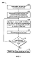
- FIG. 3 is a flowchart 200 which illustrates operation of the active ringdown control embodiments described herein.
- a current induced into the transmitter e.g. transmitter 10 shown in Figure 1 by the collapsing electromagnetic field at the load (antenna 16) may be measured 204.
- the modulator of the transmitter may be configured 206 such that a current of substantially equal value and opposite polarity is output to the load.
- the current at the load is again measured 208. If the current measurement is below 210 a pre-defined level, a detuning circuit may be switched 212 onto the load. If the current is not below 210 the pre-defined level, the modulator may again be configured as described above, and the measurement process is repeated.
- the current may be driven towards zero in one embodiment by reversing the polarity of a drive signal after the end of the transmission burst and then using feedback to control an amount of the reversed polarity current output by a pulse width modulator and amplifier of the transmitter.
- a de-Q'ing circuit may be switched onto the antenna load to dissipate any remaining transmitter signal.
- the remaining transmitter signal at this point in time is much lower in amplitude, the power dissipation requirements (and therefore the cost and size) of the de-Q'ing circuit components are much smaller than those utilized in known circuit ringdown applications.
- a de-Q'ing circuit may still be needed in certain embodiments because of discrepancies in dynamic range between the current sensing hardware for feedback and the receiver dynamic range, i.e., the smallest signal that can be sensed by the current sensing hardware is on the order of several milliamps. However, this is still typically much larger than the EAS tag signals that are to be detected. In addition, such a configuration significantly reduces the thermal load on the damping components, which improves reliability of the EAS transmitter. More specifically, the various embodiments provide advantages over the prior art by allowing lower cost and higher reliability due to the lower power dissipation requirements of the thermally critical de-Qing circuit 52.
- FIG 4 is an illustration of an EAS system 250 which is capable of incorporating the embodiments described herein.
- EAS system 250 includes a first antenna pedestal 252 and a second antenna pedestal 254.
- the antenna pedestals 252 and 254 are connected to a control unit 256 which includes a transmitter 258 and a receiver 260.
- a controller 262 may be configured for communication with an external device.
- controller 262 may be configured to control transmissions from transmitter 258 and receptions at receiver 260 such that the antenna pedestals 252 and 254 can be utilized for both transmission of signals to an EAS tag 270 and reception of frequencies generated by EAS tag 270.
- System 250 is representative of many EAS systems and is meant as an example only.
- control unit 256 may be located within one of the antenna pedestals.
- additional antennas which only receive frequencies from the EAS tags 270 may be utilized as part of the EAS system.
- a single control unit 256 either within a pedestal or located separately, may be configured to control multiple set of antenna pedestals.
Landscapes
- Engineering & Computer Science (AREA)
- Physics & Mathematics (AREA)
- Signal Processing (AREA)
- Automation & Control Theory (AREA)
- Computer Security & Cryptography (AREA)
- Electromagnetism (AREA)
- General Physics & Mathematics (AREA)
- Transmitters (AREA)
- Amplifiers (AREA)
- Burglar Alarm Systems (AREA)
Claims (21)
- Verfahren zum Steuern des Signalabklingens einer elektromagnetischen Übertragung von einem Sender (10, 258) für ein EAS-System (Electronic Article Surveillance - elektronische Artikelüberwachung) (250) mit Erzeugen eines Stromerfassungssignals (18),
dadurch gekennzeichnet, daß das Erzeugen das Messen eines durch ein nach der elektromagnetischen Übertragung verbleibendes abklingendes Feld in den Sender (10, 258) induzierten Stromwertes (14) umfaßt; und
Benutzen der Strommessung zum Steuern einer Abklingrate des abklingenden Feldes. - Verfahren nach Anspruch 1, wobei das Verwenden der Strommessung zum Steuern der Abklingrate das Anlegen einer Spannung der entgegengesetzten Polarität wie der Polarität des gemessenen Stroms umfaßt.
- Verfahren nach Anspruch 1, gekennzeichnet durch Messen eines vom Sender (10, 258) während eines Übertragungsburst des ausgegebenen Stromwertes (14); und
Verwenden der Strommessungen (14) zum Steuern einer Burststeuerungsalgorithmuskomponente (30) zum Steuern der Erzeugung des übertragenen Signals während einer Übertragungszeit des Senders (10, 258). - Verfahren nach Anspruch 1, gekennzeichnet durch Bestimmen der Vollendung einer ersten elektromagnetischen Übertragung; und
Einleiten einer zweiten elektromagnetischen Übertragung mit einer entgegengesetzten Polarität wie die erste elektromagnetische Übertragung. - Verfahren nach Anspruch 1, gekennzeichnet durch Bestimmen, wann der in den Sender (10, 258) induzierte Strom (14) auf einen Wert abgeklungen ist; und
Anlegen einer Verstimmungsschaltung (52) an den Sender (10, 258). - Verfahren nach Anspruch 1, wobei Verwenden der Strommessung Verwenden der Strommessung zum Bestimmen eines vom Sender (10, 258) auszugebenden Wertes von Strom entgegengesetzter Polarität umfaßt.
- Verfahren nach Anspruch 1, wobei Verwenden der Strommessung folgendes umfaßt:Bestimmen einer Größe des in den Sender (10, 258) induzierten Stroms aus gleichphasigen und Quadraturkomponenten der Strommessung; und Vergleichen der Größe der Strommessung mit einem gewünschten Senderstrom zum Einstellen eines Stromausgangspegels für den Sender (10, 258).
- Sender (10, 258) für ein EAS-System (Electronic Article Surveillance - elektronische Artikelüberwachung) (250), zum Ausgeben eines Übertragungssignals an eine externe Last, wobei der Sender eine Stromerfassungsschaltung (12) mindestens zum Senden eines Stromwertes (14) umfaßt, dadurch gekennzeichnet, daß der Strom (14) ein in den Sender (10, 258) von der Last nach Übertragung des Signals zurückinduzierter Strom ist, und
eine Sendersteuerschaltung (262) zum Verwenden des erfaßten Stroms (18) zum Bestimmen eines Wertes und einer Polarität von an die Last anzulegendem Strom zum Verringern des induzierten Stroms auf einen gewünschten Wert. - Sender (10, 258) nach Anspruch 8, dadurch gekennzeichnet, daß der Sender (10, 258) einen Modulator (34) zum Ausgeben des Übertragungssignals (36) umfaßt, wobei die Sendersteuerschaltung zum Umsteuern der Polarität des Übertragungssignals (36) nach Abschluß einer Übertragungszeit konfiguriert ist.
- Sender (10, 258) nach Anspruch 8, dadurch gekennzeichnet, daß die Stromerfassungsschaltung (12) einen Analog-Digitalwandler (20) umfaßt.
- Sender (10, 258) nach Anspruch 8, dadurch gekennzeichnet, daß die Stromerfassungsschaltung (12) weiterhin zum Erfassen eines an die Last während einer Signalübertragung angelegten Stromwertes (14) konfiguriert ist, wobei die Sendersteuerschaltung einen mit den Übertragungszeiten des Senders (10, 258) programmierten Burstende-Übergangssteuerungsalgorithmus (40) umfaßt, wobei der Burstende-Übergangssteuerungsalgorithmus (40) zum Umschalten der erfaßten Stromsignale (18, 22) von einem Burststeuerungsalgorithmus (30) zu einem Abklingsteuerungsalgorithmus (32) nach Vollendung einer Übertragungszeit des Senders konfiguriert ist.
- Sender (10, 258) nach Anspruch 8, dadurch gekennzeichnet, daß er weiterhin folgendes umfaßt:eine Verstimmungsschaltung (52), und wobei die Sendersteuerungsschaltung einen Abklingende-Übergangssteuerungsalgorithmus (50) umfaßt, der zum Aufschalten der Verstimmungsschaltung (52) auf die Last (212) bei Bestimmung, daß ein nach Abschluß einer Übertragungszeit an die Last angelegter Stromwert (14) unter einem Schwellwert liegt, programmiert ist.
- Sender (10, 258) nach Anspruch 8, dadurch gekennzeichnet, daß die Sendersteuerungsschaltung einen Bürststeuerungsalgorithmus (30) zum Empfangen des erfaßten Stroms (18) während einer Übertragungszeit des Senders umfaßt, wobei der Burststeuerungsalgorithmus (30) eine Steuerung (262) umfaßt, die für folgendes programmiert ist:Vergleichen eines an die Last angelegten Stromwertes (14) mit einem gewünschten Laststrom mit dem Ergebnis eines Fehlersignals (120); undVerwenden des Fehlersignals (120) zum Einstellen eines an die Last angelegten Stromwertes.
- Sender (10, 258) nach Anspruch 8, dadurch gekennzeichnet, daß die Sendersteuerungsschaltung einen Abklingsteuerungsalgorithmus (32) zum Empfangen des in den Sender durch die Last induzierten erfaßten Stroms (18) umfaßt, wobei der Abklingsteuerungsalgorithmus (32) eine Steuerung (262) umfaßt, die für folgendes programmiert ist:Vergleichen eines von der Last in den Sender zurückinduzierten Stromwertes (14) mit einem gewünschten Stromwert mit dem Ergebnis eines Fehlersignals (120); undVerwenden des Fehlersignals (120) zum Bestimmen eines Wertes und einer Polarität eines an die Last anzulegenden Stroms.
- Sender (10, 258) nach Anspruch 8, dadurch gekennzeichnet, daß die Sendersteuerungsschaltung einen Proportional-Integral-Differential-Regler (262) umfaßt.
- Sender (10, 258) nach Anspruch 8, dadurch gekennzeichnet, daß die Sendersteuerungsschaltung einen Abklingsteuerungsalgorithmus (32) zum Empfangen des erfaßten Stroms (18) während einer Nichtübertragungszeit des Senders umfaßt, wobei der Abklingsteuerungsalgorithmus (32) eine Steuerung (262) umfaßt, die für folgendes programmiert ist:Vergleichen eines durch die Last in den Sender zurückinduzierten . Stromwertes (14) mit einem gewünschten Stromwert mit dem Ergebnis eines Fehlersignals (120); undAnlegen des Fehlersignals (120) an einen Regler (262) zum Regeln eines Wertes und einer Polarität von an die Last angelegtem Strom.
- EAS-System (Electronic Article Surveillance - elektronische Artikelüberwachung) (250) mit folgendem:einem Empfänger (260) zum Empfangen von durch EAS-Etiketten (270) erzeugten Signalen; undeinem Sender (258) nach Anspruch 8, weiterhin zum Übertragen eines Signals mit einer Resonanzfrequenz des EAS-Etiketts (270) zum Erfassen eines während Übertragungszeiten an die Last angelegten Stromwertes (14), und zum Benutzen der erfaßten Ströme (18) zum Steuern eines Betrags und einer Polarität von während sowohl Übertragungszeiten als auch Nichtübertragungszeiten an die Last angelegten Stroms.
- EAS-System (270) nach Anspruch 17, dadurch gekennzeichnet, daß der Sender (258) einen den Strom an die Last anlegenden Modulator (34) und eine Sendersteuerungsschaltung zum Umsteuern einer Polarität eines von dem Modulator (34) nach Abschluß einer Übertragungszeit ausgegebenen Signals umfaßt.
- EAS-System (270) nach Anspruch 17, dadurch gekennzeichnet, daß der Sender (258) einen mit den Übertragungszeiten des Senders (10, 258) konfigurierten Burstende-Übergangssteuerungsalgorithmus (40) umfaßt, wobei der Burstende-Übergangssteuerungsalgorithmus (40) zum Umschalten der erfaßten Stromsignale (18) von einem Burststeuerungsalgorithmus zu einem Abklingsteuerungsalgorithmus (32) nach Abschluß einer Übertragungszeit des Senders (10, 258) konfiguriert ist.
- EAS-System (270) nach Anspruch 17, dadurch gekennzeichnet, daß der Sender (258) eine Verstimmungsschaltung (52) umfaßt; und einen Abklingende-Übergangssteuerungsalgorithmus (50), der zum Aufschalten der Verstimmungsschaltung (52) auf die Last bei Bestimmung, daß ein Wert von an die Last angelegtem Strom unter einem Schwellwert liegt, programmiert ist.
- EAS-System (270) nach Anspruch 17, dadurch gekennzeichnet, daß der Sender (258) einen Abklingsteuerungsalgorithmus (32) zum Empfangen des während einer Nichtübertragungszeit des Senders in den Sender zurückinduzierten erfaßten Stroms (22) umfaßt, wobei der Abklingsteuerungsalgorithmus (32) eine Steuerung (262) umfaßt, die zum Vergleichen eines durch die Last in den Sender induzierten Stromwertes mit einem gewünschten Stromwert mit dem Ergebnis eines Fehlersignals und Verwenden des Fehlersignals zum Bestimmen eines Wertes und einer Polarität eines an die Last anzulegenden Stroms programmiert ist.
Applications Claiming Priority (4)
| Application Number | Priority Date | Filing Date | Title |
|---|---|---|---|
| US121899P | 1999-02-26 | ||
| US57003104P | 2004-05-11 | 2004-05-11 | |
| US570031P | 2004-05-11 | ||
| US11/121,899 US7444120B2 (en) | 2004-05-11 | 2005-05-04 | Active transmitter ringdown for switching power amplifier |
Publications (2)
| Publication Number | Publication Date |
|---|---|
| EP1596345A1 EP1596345A1 (de) | 2005-11-16 |
| EP1596345B1 true EP1596345B1 (de) | 2007-07-11 |
Family
ID=34936322
Family Applications (1)
| Application Number | Title | Priority Date | Filing Date |
|---|---|---|---|
| EP05010093A Expired - Lifetime EP1596345B1 (de) | 2004-05-11 | 2005-05-10 | Aktiver Abkling-Sender für Schaltleistungsverstärkung |
Country Status (6)
| Country | Link |
|---|---|
| US (1) | US7444120B2 (de) |
| EP (1) | EP1596345B1 (de) |
| JP (1) | JP4255456B2 (de) |
| AT (1) | ATE366972T1 (de) |
| CA (1) | CA2507037C (de) |
| DE (1) | DE602005001574T2 (de) |
Families Citing this family (5)
| Publication number | Priority date | Publication date | Assignee | Title |
|---|---|---|---|---|
| US7285958B2 (en) * | 2004-01-15 | 2007-10-23 | Metrotech Corporation, Inc. | Method and apparatus for digital detection of electronic markers using frequency adaptation |
| JP4550447B2 (ja) | 2004-02-25 | 2010-09-22 | 独立行政法人科学技術振興機構 | 核酸固相合成用シリルリンカー |
| KR100656209B1 (ko) * | 2005-11-28 | 2006-12-13 | 삼성전자주식회사 | 무선 식별 태그의 응답 종점 검출 방법 및 장치 |
| US20070290856A1 (en) * | 2006-06-19 | 2007-12-20 | Tagsys Sas | RFID tag detuning |
| ES2323928B1 (es) * | 2007-11-14 | 2010-05-13 | Jaime Perez Boils | Sistema antihurto perfeccionado. |
Family Cites Families (9)
| Publication number | Priority date | Publication date | Assignee | Title |
|---|---|---|---|---|
| US5239696A (en) * | 1991-10-15 | 1993-08-24 | Sensormatic Electronics Corporation | Linear power amplifier utilizing current feedback |
| US5434396A (en) * | 1992-11-10 | 1995-07-18 | Xicor Inc. | Wireless powering and communication system for communicating data between a host system and a stand-alone device |
| EP0650074A1 (de) * | 1993-10-22 | 1995-04-26 | Texas Instruments Holland B.V. | Genaues Hochfrequenz-Identifizierungs- und Ortsbestimmungssystem |
| US5815076A (en) * | 1996-01-16 | 1998-09-29 | Sensormatic Electronics Corporation | Pulsed-signal magnetomechanical electronic article surveillance system with improved damping of transmitting antenna |
| US5781111A (en) * | 1996-09-26 | 1998-07-14 | Sensormatic Electronics Corporation | Apparatus for deactivation of electronic article surveillance tags |
| JP4019469B2 (ja) * | 1997-10-02 | 2007-12-12 | 株式会社日本自動車部品総合研究所 | 電磁誘導式自動認識装置 |
| US6476708B1 (en) * | 1998-03-20 | 2002-11-05 | Hid Corporation | Detection of an RFID device by an RF reader unit operating in a reduced power state |
| US6696951B2 (en) * | 2001-06-13 | 2004-02-24 | 3M Innovative Properties Company | Field creation in a magnetic electronic article surveillance system |
| US6947860B2 (en) * | 2002-08-09 | 2005-09-20 | Sensormatic Electronics Corporation | Electronic article surveillance system stationary tag response canceller |
-
2005
- 2005-05-04 US US11/121,899 patent/US7444120B2/en active Active
- 2005-05-10 DE DE602005001574T patent/DE602005001574T2/de not_active Expired - Lifetime
- 2005-05-10 AT AT05010093T patent/ATE366972T1/de not_active IP Right Cessation
- 2005-05-10 EP EP05010093A patent/EP1596345B1/de not_active Expired - Lifetime
- 2005-05-10 CA CA002507037A patent/CA2507037C/en not_active Expired - Lifetime
- 2005-05-11 JP JP2005138117A patent/JP4255456B2/ja not_active Expired - Fee Related
Non-Patent Citations (1)
| Title |
|---|
| None * |
Also Published As
| Publication number | Publication date |
|---|---|
| US20050253721A1 (en) | 2005-11-17 |
| CA2507037A1 (en) | 2005-11-11 |
| HK1089817A1 (zh) | 2006-12-08 |
| DE602005001574T2 (de) | 2007-11-22 |
| EP1596345A1 (de) | 2005-11-16 |
| DE602005001574D1 (de) | 2007-08-23 |
| ATE366972T1 (de) | 2007-08-15 |
| US7444120B2 (en) | 2008-10-28 |
| JP4255456B2 (ja) | 2009-04-15 |
| JP2005328534A (ja) | 2005-11-24 |
| CA2507037C (en) | 2009-04-21 |
Similar Documents
| Publication | Publication Date | Title |
|---|---|---|
| CA2729792C (en) | Electronic article surveillance system with metal detection capability and method therefor | |
| EP1216464B1 (de) | Regelung des senders einer elektronischen warenüberwachungseinrrichtung (eas) durch zielentfernung | |
| AU710093B2 (en) | Pulsed-signal magnetomechanical electronic article surveillance system with improved damping of transmitting antenna | |
| US5049857A (en) | Multi-mode electronic article surveillance system | |
| FI97860C (fi) | Menetelmä sydänsykkeen häiriösietoiseksi mittaamiseksi | |
| CA2006622A1 (en) | Identification system | |
| US5404114A (en) | Method and apparatus for providing transmitter protection | |
| US7444120B2 (en) | Active transmitter ringdown for switching power amplifier | |
| EP1020829A2 (de) | Deaktivierungsvermeidung für elektronische Warenüberwachungssysteme | |
| US5805065A (en) | Electro-magnetic desensitizer | |
| CN100422766C (zh) | 用于切换功率放大器的有源发射机环降 | |
| HK1089817B (en) | Active transmitter ringdown for switching power amplifier | |
| WO2005116946A3 (en) | Method and apparatus for deactivating an eas device | |
| US5729202A (en) | Electronic article-surveillance apparatus and method of operating same | |
| EP1596346B1 (de) | Sendesteuerung mit geschlossenem Regelkreis für einen Leistungsverstärker in einem elektronischen Artikelüberwachungssystem | |
| JPH08201519A (ja) | 光受信回路 | |
| JPH01114213A (ja) | 信号弁別器 | |
| HK1086676B (en) | Transmitter for an electronic article surveillance system and method for controlling the same | |
| CN121811560A (zh) | 一种可灭活两种频率防盗软标签的灭活系统及其灭活方法 | |
| JP2005071288A (ja) | リモート測定装置 | |
| HK1117236A (en) | Adaptively transmitting a signal for activating a tag |
Legal Events
| Date | Code | Title | Description |
|---|---|---|---|
| PUAI | Public reference made under article 153(3) epc to a published international application that has entered the european phase |
Free format text: ORIGINAL CODE: 0009012 |
|
| 17P | Request for examination filed |
Effective date: 20050728 |
|
| AK | Designated contracting states |
Kind code of ref document: A1 Designated state(s): AT BE BG CH CY CZ DE DK EE ES FI FR GB GR HU IE IS IT LI LT LU MC NL PL PT RO SE SI SK TR |
|
| AX | Request for extension of the european patent |
Extension state: AL BA HR LV MK YU |
|
| AKX | Designation fees paid |
Designated state(s): AT BE BG CH CY CZ DE DK EE ES FI FR GB GR HU IE IS IT LI LT LU MC NL PL PT RO SE SI SK TR |
|
| GRAP | Despatch of communication of intention to grant a patent |
Free format text: ORIGINAL CODE: EPIDOSNIGR1 |
|
| GRAS | Grant fee paid |
Free format text: ORIGINAL CODE: EPIDOSNIGR3 |
|
| GRAA | (expected) grant |
Free format text: ORIGINAL CODE: 0009210 |
|
| AK | Designated contracting states |
Kind code of ref document: B1 Designated state(s): AT BE BG CH CY CZ DE DK EE ES FI FR GB GR HU IE IS IT LI LT LU MC NL PL PT RO SE SI SK TR |
|
| REG | Reference to a national code |
Ref country code: GB Ref legal event code: FG4D |
|
| REG | Reference to a national code |
Ref country code: CH Ref legal event code: EP |
|
| REF | Corresponds to: |
Ref document number: 602005001574 Country of ref document: DE Date of ref document: 20070823 Kind code of ref document: P |
|
| REG | Reference to a national code |
Ref country code: IE Ref legal event code: FG4D |
|
| REG | Reference to a national code |
Ref country code: SE Ref legal event code: TRGR |
|
| ET | Fr: translation filed | ||
| PG25 | Lapsed in a contracting state [announced via postgrant information from national office to epo] |
Ref country code: FI Free format text: LAPSE BECAUSE OF FAILURE TO SUBMIT A TRANSLATION OF THE DESCRIPTION OR TO PAY THE FEE WITHIN THE PRESCRIBED TIME-LIMIT Effective date: 20070711 Ref country code: ES Free format text: LAPSE BECAUSE OF FAILURE TO SUBMIT A TRANSLATION OF THE DESCRIPTION OR TO PAY THE FEE WITHIN THE PRESCRIBED TIME-LIMIT Effective date: 20071022 Ref country code: PT Free format text: LAPSE BECAUSE OF FAILURE TO SUBMIT A TRANSLATION OF THE DESCRIPTION OR TO PAY THE FEE WITHIN THE PRESCRIBED TIME-LIMIT Effective date: 20071211 Ref country code: BG Free format text: LAPSE BECAUSE OF FAILURE TO SUBMIT A TRANSLATION OF THE DESCRIPTION OR TO PAY THE FEE WITHIN THE PRESCRIBED TIME-LIMIT Effective date: 20071011 Ref country code: NL Free format text: LAPSE BECAUSE OF FAILURE TO SUBMIT A TRANSLATION OF THE DESCRIPTION OR TO PAY THE FEE WITHIN THE PRESCRIBED TIME-LIMIT Effective date: 20070711 Ref country code: LT Free format text: LAPSE BECAUSE OF FAILURE TO SUBMIT A TRANSLATION OF THE DESCRIPTION OR TO PAY THE FEE WITHIN THE PRESCRIBED TIME-LIMIT Effective date: 20070711 Ref country code: IS Free format text: LAPSE BECAUSE OF FAILURE TO SUBMIT A TRANSLATION OF THE DESCRIPTION OR TO PAY THE FEE WITHIN THE PRESCRIBED TIME-LIMIT Effective date: 20071111 |
|
| REG | Reference to a national code |
Ref country code: CH Ref legal event code: PL |
|
| NLV1 | Nl: lapsed or annulled due to failure to fulfill the requirements of art. 29p and 29m of the patents act | ||
| PG25 | Lapsed in a contracting state [announced via postgrant information from national office to epo] |
Ref country code: LI Free format text: LAPSE BECAUSE OF FAILURE TO SUBMIT A TRANSLATION OF THE DESCRIPTION OR TO PAY THE FEE WITHIN THE PRESCRIBED TIME-LIMIT Effective date: 20070711 Ref country code: PL Free format text: LAPSE BECAUSE OF FAILURE TO SUBMIT A TRANSLATION OF THE DESCRIPTION OR TO PAY THE FEE WITHIN THE PRESCRIBED TIME-LIMIT Effective date: 20070711 Ref country code: AT Free format text: LAPSE BECAUSE OF FAILURE TO SUBMIT A TRANSLATION OF THE DESCRIPTION OR TO PAY THE FEE WITHIN THE PRESCRIBED TIME-LIMIT Effective date: 20070711 Ref country code: CH Free format text: LAPSE BECAUSE OF FAILURE TO SUBMIT A TRANSLATION OF THE DESCRIPTION OR TO PAY THE FEE WITHIN THE PRESCRIBED TIME-LIMIT Effective date: 20070711 |
|
| PG25 | Lapsed in a contracting state [announced via postgrant information from national office to epo] |
Ref country code: BE Free format text: LAPSE BECAUSE OF FAILURE TO SUBMIT A TRANSLATION OF THE DESCRIPTION OR TO PAY THE FEE WITHIN THE PRESCRIBED TIME-LIMIT Effective date: 20070711 |
|
| PG25 | Lapsed in a contracting state [announced via postgrant information from national office to epo] |
Ref country code: GR Free format text: LAPSE BECAUSE OF FAILURE TO SUBMIT A TRANSLATION OF THE DESCRIPTION OR TO PAY THE FEE WITHIN THE PRESCRIBED TIME-LIMIT Effective date: 20071012 Ref country code: DK Free format text: LAPSE BECAUSE OF FAILURE TO SUBMIT A TRANSLATION OF THE DESCRIPTION OR TO PAY THE FEE WITHIN THE PRESCRIBED TIME-LIMIT Effective date: 20070711 |
|
| PLBE | No opposition filed within time limit |
Free format text: ORIGINAL CODE: 0009261 |
|
| STAA | Information on the status of an ep patent application or granted ep patent |
Free format text: STATUS: NO OPPOSITION FILED WITHIN TIME LIMIT |
|
| PG25 | Lapsed in a contracting state [announced via postgrant information from national office to epo] |
Ref country code: CZ Free format text: LAPSE BECAUSE OF FAILURE TO SUBMIT A TRANSLATION OF THE DESCRIPTION OR TO PAY THE FEE WITHIN THE PRESCRIBED TIME-LIMIT Effective date: 20070711 Ref country code: SK Free format text: LAPSE BECAUSE OF FAILURE TO SUBMIT A TRANSLATION OF THE DESCRIPTION OR TO PAY THE FEE WITHIN THE PRESCRIBED TIME-LIMIT Effective date: 20070711 |
|
| 26N | No opposition filed |
Effective date: 20080414 |
|
| PG25 | Lapsed in a contracting state [announced via postgrant information from national office to epo] |
Ref country code: RO Free format text: LAPSE BECAUSE OF FAILURE TO SUBMIT A TRANSLATION OF THE DESCRIPTION OR TO PAY THE FEE WITHIN THE PRESCRIBED TIME-LIMIT Effective date: 20070711 |
|
| PG25 | Lapsed in a contracting state [announced via postgrant information from national office to epo] |
Ref country code: MC Free format text: LAPSE BECAUSE OF NON-PAYMENT OF DUE FEES Effective date: 20080531 |
|
| PG25 | Lapsed in a contracting state [announced via postgrant information from national office to epo] |
Ref country code: EE Free format text: LAPSE BECAUSE OF FAILURE TO SUBMIT A TRANSLATION OF THE DESCRIPTION OR TO PAY THE FEE WITHIN THE PRESCRIBED TIME-LIMIT Effective date: 20070711 |
|
| PG25 | Lapsed in a contracting state [announced via postgrant information from national office to epo] |
Ref country code: IE Free format text: LAPSE BECAUSE OF NON-PAYMENT OF DUE FEES Effective date: 20080512 |
|
| PG25 | Lapsed in a contracting state [announced via postgrant information from national office to epo] |
Ref country code: SI Free format text: LAPSE BECAUSE OF FAILURE TO SUBMIT A TRANSLATION OF THE DESCRIPTION OR TO PAY THE FEE WITHIN THE PRESCRIBED TIME-LIMIT Effective date: 20070711 |
|
| PG25 | Lapsed in a contracting state [announced via postgrant information from national office to epo] |
Ref country code: CY Free format text: LAPSE BECAUSE OF FAILURE TO SUBMIT A TRANSLATION OF THE DESCRIPTION OR TO PAY THE FEE WITHIN THE PRESCRIBED TIME-LIMIT Effective date: 20070711 |
|
| PG25 | Lapsed in a contracting state [announced via postgrant information from national office to epo] |
Ref country code: HU Free format text: LAPSE BECAUSE OF FAILURE TO SUBMIT A TRANSLATION OF THE DESCRIPTION OR TO PAY THE FEE WITHIN THE PRESCRIBED TIME-LIMIT Effective date: 20080112 Ref country code: LU Free format text: LAPSE BECAUSE OF NON-PAYMENT OF DUE FEES Effective date: 20080510 |
|
| PG25 | Lapsed in a contracting state [announced via postgrant information from national office to epo] |
Ref country code: TR Free format text: LAPSE BECAUSE OF FAILURE TO SUBMIT A TRANSLATION OF THE DESCRIPTION OR TO PAY THE FEE WITHIN THE PRESCRIBED TIME-LIMIT Effective date: 20070711 |
|
| PG25 | Lapsed in a contracting state [announced via postgrant information from national office to epo] |
Ref country code: IT Free format text: LAPSE BECAUSE OF NON-PAYMENT OF DUE FEES Effective date: 20080531 |
|
| PGFP | Annual fee paid to national office [announced via postgrant information from national office to epo] |
Ref country code: SE Payment date: 20110527 Year of fee payment: 7 |
|
| PGFP | Annual fee paid to national office [announced via postgrant information from national office to epo] |
Ref country code: DE Payment date: 20110527 Year of fee payment: 7 |
|
| REG | Reference to a national code |
Ref country code: FR Ref legal event code: TP Owner name: SENSORMATIC ELECTRONICS, LLC, US Effective date: 20110913 |
|
| REG | Reference to a national code |
Ref country code: SE Ref legal event code: EUG |
|
| PG25 | Lapsed in a contracting state [announced via postgrant information from national office to epo] |
Ref country code: SE Free format text: LAPSE BECAUSE OF NON-PAYMENT OF DUE FEES Effective date: 20120511 |
|
| REG | Reference to a national code |
Ref country code: DE Ref legal event code: R119 Ref document number: 602005001574 Country of ref document: DE Effective date: 20121201 |
|
| PG25 | Lapsed in a contracting state [announced via postgrant information from national office to epo] |
Ref country code: DE Free format text: LAPSE BECAUSE OF NON-PAYMENT OF DUE FEES Effective date: 20121201 |
|
| REG | Reference to a national code |
Ref country code: GB Ref legal event code: 732E Free format text: REGISTERED BETWEEN 20150205 AND 20150211 |
|
| REG | Reference to a national code |
Ref country code: GB Ref legal event code: 732E Free format text: REGISTERED BETWEEN 20150305 AND 20150311 |
|
| REG | Reference to a national code |
Ref country code: FR Ref legal event code: PLFP Year of fee payment: 11 |
|
| REG | Reference to a national code |
Ref country code: FR Ref legal event code: TP Owner name: TYCO FIRE & SECURITY GMBH, CH Effective date: 20160115 |
|
| REG | Reference to a national code |
Ref country code: FR Ref legal event code: PLFP Year of fee payment: 12 |
|
| REG | Reference to a national code |
Ref country code: FR Ref legal event code: PLFP Year of fee payment: 13 |
|
| REG | Reference to a national code |
Ref country code: FR Ref legal event code: PLFP Year of fee payment: 14 |
|
| REG | Reference to a national code |
Ref country code: GB Ref legal event code: 732E Free format text: REGISTERED BETWEEN 20191205 AND 20191211 |
|
| PGFP | Annual fee paid to national office [announced via postgrant information from national office to epo] |
Ref country code: GB Payment date: 20240521 Year of fee payment: 20 |
|
| PGFP | Annual fee paid to national office [announced via postgrant information from national office to epo] |
Ref country code: FR Payment date: 20240527 Year of fee payment: 20 |
|
| REG | Reference to a national code |
Ref country code: GB Ref legal event code: PE20 Expiry date: 20250509 |
|
| PG25 | Lapsed in a contracting state [announced via postgrant information from national office to epo] |
Ref country code: GB Free format text: LAPSE BECAUSE OF EXPIRATION OF PROTECTION Effective date: 20250509 |