EP1596323B1 - Anordnung zur Erkennung bestimmter Objekte - Google Patents
Anordnung zur Erkennung bestimmter Objekte Download PDFInfo
- Publication number
- EP1596323B1 EP1596323B1 EP04106272A EP04106272A EP1596323B1 EP 1596323 B1 EP1596323 B1 EP 1596323B1 EP 04106272 A EP04106272 A EP 04106272A EP 04106272 A EP04106272 A EP 04106272A EP 1596323 B1 EP1596323 B1 EP 1596323B1
- Authority
- EP
- European Patent Office
- Prior art keywords
- judgment
- layer
- unit
- specified object
- image
- Prior art date
- Legal status (The legal status is an assumption and is not a legal conclusion. Google has not performed a legal analysis and makes no representation as to the accuracy of the status listed.)
- Expired - Lifetime
Links
Images








Classifications
-
- G—PHYSICS
- G06—COMPUTING OR CALCULATING; COUNTING
- G06V—IMAGE OR VIDEO RECOGNITION OR UNDERSTANDING
- G06V10/00—Arrangements for image or video recognition or understanding
- G06V10/70—Arrangements for image or video recognition or understanding using pattern recognition or machine learning
- G06V10/77—Processing image or video features in feature spaces; using data integration or data reduction, e.g. principal component analysis [PCA] or independent component analysis [ICA] or self-organising maps [SOM]; Blind source separation
- G06V10/774—Generating sets of training patterns; Bootstrap methods, e.g. bagging or boosting
- G06V10/7747—Organisation of the process, e.g. bagging or boosting
-
- G—PHYSICS
- G06—COMPUTING OR CALCULATING; COUNTING
- G06F—ELECTRIC DIGITAL DATA PROCESSING
- G06F18/00—Pattern recognition
- G06F18/20—Analysing
- G06F18/21—Design or setup of recognition systems or techniques; Extraction of features in feature space; Blind source separation
- G06F18/214—Generating training patterns; Bootstrap methods, e.g. bagging or boosting
- G06F18/2148—Generating training patterns; Bootstrap methods, e.g. bagging or boosting characterised by the process organisation or structure, e.g. boosting cascade
-
- G—PHYSICS
- G06—COMPUTING OR CALCULATING; COUNTING
- G06V—IMAGE OR VIDEO RECOGNITION OR UNDERSTANDING
- G06V40/00—Recognition of biometric, human-related or animal-related patterns in image or video data
- G06V40/10—Human or animal bodies, e.g. vehicle occupants or pedestrians; Body parts, e.g. hands
- G06V40/16—Human faces, e.g. facial parts, sketches or expressions
- G06V40/161—Detection; Localisation; Normalisation
Definitions
- the present invention relates to a technique effectively applicable to an apparatus and a method for detecting from a picked-up image a specified object or a part of the object such as a man, an animal or any other physical object included in the particular image.
- a conventional technique is available for detecting a specified object or a part of the object such as a man, an animal or any other physical object included in a picked-up image.
- An example of this conventional technique is to detect a human face from a picked-up image (See Paul Viola, Michael Jones, "Robust Real-Time Object Detection” SECOND INTERNATIONAL WORKSHOP ON STATISTICAL AND COMPUTATIONAL THEORIES OF VISION-MODELING, LEARNING, COMPUTING, AND SAMPLING VANCOUVER, CANADA, JULY 13, 2001 (hereinafter referred to as Non-patent Reference 1)).
- Non-patent Reference 1 a specified rectangle (hereinafter referred to as “the face judging rectangle") to be processed is moved in an image thereby to judge whether a human face is included in the face judging rectangle of each destination (hereinafter referred to as "the intended area").
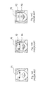
- Fig. 14 is a diagram showing an example of the face judging rectangle (face judging rectangle P1). With reference to Fig. 14 , the process of detecting a human face using the face judging rectangle P1 is explained.
- the face judging rectangle P1 includes therein a plurality of other rectangles (hereinafter referred to as "the first rectangle", “the second rectangle") P2, P3.
- the first rectangle P2 and the second rectangle P3 are arranged at predetermined positions in the face judging rectangle P1.
- At least one first rectangle P2 and at least one second rectangle P3 are arranged in one face judging rectangle P1. Examples of such rectangles are shown and commented in paragraph 2 and figure 1 of the proceeding 2001 of IEEE conference on computer vision and pattern recognition, a report from Viola and Jones entitled “Rapid object detection using a boosted cascade of simple features" pages I-511-517.
- the article reports a method for combining increasingly more complex classifier in a cascade which allows background region of the image to be quickly discarded while spending more time on promising object like regions.
- a positive result from the first classifier triggers the evaluation of a second classifier which has also been adjusted to achieve very high detection rates.
- a positive result from the second classifier triggers a third classifier and so on.
- a negative outcome at any point leads to the immediate rejection of the sub window.
- the default Adaboost threshold is adapted is adjusted to minimize false negative.
- the feature of each area defined by the first rectangle P2 and the second rectangle P3 (hereinafter referred to as “the first feature area” and “the second feature area”) in each intended area is calculated.
- the feature of the first feature area or the second feature area indicates, for example, an average pixel value in the respective area.
- the difference between the feature La of the first feature area and the feature Lb of the second feature area is calculated.
- this differential value is larger or not than a preset threshold value ⁇ , it is judged whether a human face is included in the intended area or not.
- the threshold value ⁇ is determined by learning using a sample image.
- a plurality of patterns of the face judging rectangle are prepared, and the judgment is made for each pattern.
- Each pattern has a different number or position of the first rectangles P2 or the second rectangles P3. Based on each judgment result, it is finally judged whether the intended area includes a human face or not.
- the accuracy of detecting a human face in an image has been improved by employing a method using the face judging rectangle P1 as described above.
- the process of detecting a human face in an image is required to be executed in real time on a device such as a portable telephone having a machine specification not comparatively highly sophisticated. Therefore, an improved processing speed is also required.
- the accuracy of human face detection in an image is still required.
- the object of this invention is to solve this problem and provide a device for realizing a high speed and a high accuracy of the process of judging whether a human face is included in a given intended area in an image.
- a specified object detection apparatus and a method for detection of a specified object in an intended area of an image according to the attached independent claims. Further, dependent claims recite advantageous mode of realization of the present invention.
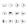
- Fig. 1 shows an example of a pattern of a face rectangle.
- Fig. 2 shows the process flow for face detection.
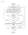
- Fig. 3 shows a flowchart of the face detection process.
- Fig. 4 shows a method of selecting an intended area with the size thereof fixed.
- Fig. 5 shows a method of selecting an intended area with the size of a human image fixed.
- Fig. 6 shows an example of the process in each layer according to a first embodiment.
- Fig. 7 shows an example of an integrated image.
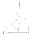
- Fig. 8 shows an example of a histogram of the differential value versus the number of images.
- Fig. 9 shows an example of the judgment value applied to each section of the histogram according to the first embodiment.
- Fig. 10 shows an example of the LUT (look-up table) according to the first embodiment.
- Fig. 11 shows a function block diagram of an example configuration of a face detection device.
- Fig. 12 shows a function block diagram of an example configuration of a judging unit.
- Fig. 13 shows a function block diagram of an example configuration of a table generating device.
- Fig. 14 shows an example of a face judging rectangle.
- Fig. 15 shows an example of the judgment value applied to each section of the histogram according to a second embodiment.
- Fig. 16 shows an example of the LUT according to the second embodiment.
- Fig. 17 shows an outline of the process in each layer according to the second embodiment.
- Fig. 18 shows a specific example of the process in each layer according to the second embodiment.
- a specified object detection apparatus is explained below with reference to the drawings.
- a face detection device 4 including 4a, 4b ( Fig. 11 ) for detecting a human face from a human image is taken as a specific example of the specified object detection apparatus.
- the human image is defined as an image containing at least a part or the whole of the human face.
- the human image therefore, may contain the whole body of a man or only the face or an upper half of the body of a man.
- the human image may include images of a plurality of men. Further, the human image may contain, on the background thereof, any pattern such as a landscape (including an intended object) other than the man.
- the face detection device 4 described below is only illustrative and the configuration thereof is not limited to the one described below.
- the face detection technique used with the face detection device 4 has several different points from the conventional face detection technique.
- the principle of the conventional face detection technique is explained first.
- the learning is executed using a sample image in advance (hereinafter referred to as “the learning process"), and the face is detected based on the learning result (hereafter referred to as “the face detection process”).
- a plurality of face images (success images) and non-face images (failure images) equal in size are prepared as sample images.
- a plurality of rectangular images having the same number of vertical and horizontal pixels are used as sample images.
- the face image is defined as an image containing a human face, and framed or trimmed in accordance with the size of the human face.
- the non-face image is an image not containing a human face and configured of an image of, for example, a landscape or an animal other than the man.
- the aforementioned face image is prepared as a success image to detect a human face as a specified object.
- the aforementioned non-face image is prepared as a failure image.
- an image containing a specified object to be detected is prepared as a success image, and an image not containing a specified object as a failure image.
- the learning process uses a rectangle defining an area of the same size as a sample image (hereinafter referred to as "the face rectangle").
- Fig. 1 is a diagram showing examples of the face rectangle.
- Each face rectangle 1 includes at least a first rectangle 2 and at least a second rectangle 3.
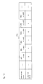
- the face rectangle 1 has a plurality of patterns in accordance with to the number and positions of the first rectangles 2 and the second rectangles 3 (A to L in Fig. 1 ).
- each face rectangle 1 has an inherent number and arrangement of the first rectangles 2 and the second rectangles 3 as a pattern.
- the learning using the face rectangle 1 and sample images is explained below.
- the data on a pattern of the face rectangle 1 are collected using all sample images.
- the feature for example, the average value of the pixels in the area
- the total value of the features of each of the respective areas is calculated as each feature.
- the feature of the first feature area is calculated as the sum of the features of the two first feature areas.
- a differential value is calculated as a relative value (such as the ratio or the difference, the latter being assumed as a relative value in the case under consideration) between the features of the first and second feature areas. This differential value indicates the feature of an intended area.
- a threshold value corresponding to the face rectangle 1 of each pattern is determined based on the calculated differential value (feature of the intended area).
- This threshold value is determined using a stochastic method. Normally, this stochastic method is designed by assuming a simple arithmetic model (such as the Gauss distribution). For example, the total (integrated value) of the number of samples is determined for each of the face image and the non-face image for the difference of zero to a specified value, and the value associated with the maximum difference of the total is set as a threshold value.
- This process is executed for the face rectangle 1 of all the patterns prepared, so that a threshold is set as a value corresponding to each of all the patterns of the face rectangles 1.
- a pattern of the face rectangle 1 to be used in the face detection process is determined.
- the judgment is carried out on the presence or absence of a face for each unit of processing called the layer. For example, the possibility of existence of a face is roughly judged in layer 1, and in the case where this possibility is zero, the process is stopped. In the case where the possibility of existence of a face is not zero, on the other hand, a more detailed judgment is made in the next layer 2.
- the face rectangle 1 of the pattern used in each of a plurality of layers (of which a specific example will be explained with reference to the face detection process) is assigned to each layer in which the presence or absence of the face is judged in the face detection process.
- This process is executed by the boosting learning algorithm such as AdaBoost.
- the number of layers required to execute the face detection process and the number of the face rectangles 1 assigned to each layer are also determined by the designer at the time of the aforementioned judgment.
- the larger the number of the face rectangles 1 used for the face detection process the higher the process accuracy. Therefore, the number of the face rectangles 1 sufficient to obtain the final judgment in the face detection process is determined by the designer based on his/her experiments and experiences. Based on this number, the designer determines the number of layers and the number of the face rectangles 1 assigned to each layer.
- FIG. 2 is a diagram showing the flow of the face detection process. First, with reference to Fig. 2 , the general flow of the face detection process is explained.
- the face detection process is executed in a plurality of layers. Each layer is assigned a different set of the face rectangles 1. In Fig. 2 , a different layer is assigned a different number of the face rectangles 1. Also, each layer is assigned the order in which the judgment is made, and each layer executes the process in accordance with that order. Specifically, in Fig. 2 , the layer 2 executes the judgment following the layer 1, followed by the layer 3.
- Each layer judges whether a human face is included in an intended area, using the face rectangle 1 of the pattern assigned to itself in the order of assignment. In the case where a given layer judges that no human face is included in an intended area, for example, the subsequent layers execute no judgment on this intended area. In the case where the last layer (layer n in Fig. 2 ) judges that a human face is included in the intended area, it is finally judged in the face detection process that a human face is included in the intended area.
- Fig. 3 is a flowchart showing the flow of the face detection process. A specific flow of the face detection process is explained with reference to Fig. 3 .
- the intended areas to be processed are selected from the human image (S01). Basically, these intended areas are selected by shifting at predetermined intervals from an end of the human image vertically or horizontally. As an example, the intended areas are selected by raster scanning of the human image. In the process, a plurality of intended areas of different sizes are selected from an arbitrary human image.
- the selecting method includes a method in which the size of the human image is changed while fixing the size of the intended area or a method in which the size of the intended area is changed while fixing the size of the human image.
- Fig. 4 is a diagram showing the method in which the size of the intended area is fixed
- Fig. 5 is a diagram showing the method in which the size of the human image is fixed.
- the face rectangle 1, the first rectangle 2 and the second rectangle 3 also change in size. Specifically, the size of the face rectangle 1 used for each layer is controlled to the same or substantially the same size as the intended area which may change in size. Thus, the size of the first rectangle 1 and the second rectangle 2 change with the size of the face rectangle 1.
- the judgment process is executed in the selected layer (S03).
- this layer judges that no human face is included in the intended area (NO in S04)
- the steps of and after S07 are executed. The steps of and after S07 are described in later.
- the judgment is that a human face is included in the intended area (YES in S04)
- it is judged whether the immediately preceding judgment (judgment in S03) is the process in the last layer or not.
- the process returns to step S02 to select the next layer and the judgment is executed in the newly selected layer.
- the face detection device 4 judges that a human face is included in this intended area. In other words, it is not until this time point when a human face is detected by the face detection device 4.
- the process returns to step S01 where the next intended area is selected and the steps of and after S02 are executed.
- the face detection process for the particular human image is terminated.
- Fig. 6 is a diagram showing an example judgment process in each layer. With reference to Fig. 6 , the layers and the judgment process in each layer are explained.
- Each layer is assigned the face rectangle 1 of at least one pattern. This assignment is made by a boosting learning algorithm such as AdaBoost in the learning process. Based on the face rectangle 1 of the pattern assigned to itself, each layer judges whether a face is included or not in an intended area.
- AdaBoost boosting learning algorithm
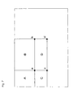
- Fig. 7 is a diagram showing an example of an integrated image. With reference to Fig. 7 , the process of calculating the feature using an integrated image is explained.
- each pixel has a pixel value equivalent to the total pixel value of all the pixels included in the upper left portion of the original image as viewed from the particular pixel.
- the pixel a in Fig. 7 has a total pixel value of all the pixels included in the area A of the original image.
- the total pixel value of all the pixels included in the area D of the original image is calculated by subtracting the pixel values b and c from the pixel value d and adding the pixel value a.
- a differential value is calculated as a relative value of the feature calculated, and based on this differential value, it is judged whether a human face is included in the intended area or not. Specifically, it is judged whether the calculated differential value is larger or smaller than the threshold value set for the face rectangle 1 of the pattern used for judgment. In accordance with the result of this judgment, the presence or absence of a human face in the intended area is determined.
- the judgment by this time is the judgment based on the face rectangle 1 of each pattern but not the judgment by a layer. In this way, the judgment is made in each layer individually based on the face rectangle 1 of all the patterns assigned thereby to obtain each judgment result (equivalent to "the individual judgment of the face rectangle" in Fig. 6 ).
- the face rectangle 1 of each pattern is assigned an individual number of points (Pt1, Pt2,..., Ptn, for example).
- the number of points assigned to the face rectangle 1 of the pattern used on that occasion is accessed and added to the number of points of the particular layer.
- the total number of points obtained in this way is calculated as the number of points for a layer (the total number of points in a layer is hereinafter referred to as "the total number of points" for distinction from the number of points for each pattern).
- the layer judges that a human face is included in the intended area.
- the total number of points for the layer fails to exceed the specified threshold value, on the other hand, the layer judges that no human face is included in the intended area.
- steps S02 to S06 the judgment is made in the layers in the descending order of the processing ease (from the layer having a smallest number of assigned face rectangles 1, for example) ( Fig. 2 ).
- the distribution of brightness in the intended area is calculated, and based on the calculated value, it is judged whether the judgment for a particular layer is made or not.
- the process of step S07 in Fig. 3 is executed. This is by reason of the fact that an intended area having substantially no brightness change (a deep black intended area or a pure white intended area, for example) is considered to contain no face without judgment for a layer.
- the conventional face detection technique used with the face detection device 4 is explained above. Next, an explanation is given about a modified process of the face detection technique used with the face detection device 4a according to a first embodiment of the invention. Specifically, the process not described below is executed the same way as the process of the face detection technique described above.
- a simple arithmetic model is assumed to calculate a threshold value for the face rectangle 1 of each pattern.
- the feature around the left and right eyes is calculated as a feature of the first feature area
- the feature around the nose and the left and right cheeks is calculated as a feature of the second feature area.
- a threshold value is calculated on the assumption that the feature of these feature areas is distributed based on a simple arithmetic model.
- the above-mentioned specific example of the first feature area is assumed to actually include three cases involving considerably different features, i.e. a case in which both the left and right eyes are closed, a case in which one of the eyes is closed, and a case in which both the left and right eyes are open.
- the face detection device 4a assumes that the differential value between the features of the two feature areas has no simple distribution such as the Gauss distribution but a distribution having a plurality of peaks.
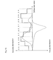
- Fig. 8 is a diagram showing an example of the histogram of the differential value calculated by collecting the data in the learning process. This histogram concerns the face rectangle 1 of a given pattern, and a similar histogram is formed for the face rectangle 1 of each pattern.
- the abscissa of the histogram represents the differential value between the features of the first feature area and the second feature area.
- the ordinate of the histogram represents the number (frequency) of the sample images for which a corresponding differential value is calculated.
- the success distribution is defined as a distribution of the sample face images, and the failure distribution a distribution for the sample non-face images.
- the abscissa is segmented at specified intervals. These intervals may have a predetermined width or a different width in accordance with the differential value.
- a judgment value is determined for each section.
- Fig. 9 is a diagram showing the manner in which a judgment value for each section is determined based on the histogram thus formed. The judgment value is a value indicating whether the image distributed in the section of a corresponding differential value has a high probability of a face image or not.
- the judgment value assumes "1", for example, in the section having a high probability of a face image (the thin colored section in Fig. 9 ), and "0" in the section having a low probability of a face image (the thick colored section in Fig. 9 ). Also, the judgment value assumes "1" in the case where the frequency of the success distribution in a given section is higher than the frequency of the failure distribution in the same section, while it assumes "0" in the case where the frequency of the success distribution in a given section is lower than the frequency of the failure distribution in the same section.
- a LUT (look-Up Table) 19a is produced.
- Fig. 10 is a diagram showing an example of the LUT 19a.
- the LUT 19a has a judgment value of the differential value corresponding to each section.
- the human face in the image is detected based on not the threshold value but the LUT 19a produced by the learning process in this way.
- the features of the first feature area and the second feature area in the intended area are calculated based on the face rectangle 1 of each pattern assigned to each layer.
- the differential value of the calculated features is calculated, and based on this differential value, it is judged whether a human face is included or not in the intended area.
- the judgment value corresponding to the calculated differential value is determined from the LUT 19a corresponding to the face rectangle 1 of each pattern, and the judgment is made by the value thus determined. In the judgment using the face rectangle 1 of the pattern corresponding to the LUT 19a shown in Fig.
- the differential value is at least not less than 40 but less than 60, not less than 100 but less than 120 or not less than 140 but less than 160. Then, it is judged that no human face is included in the intended area. In the case where the differential value is at least not less than 60 but less than 100 or not less than 120 but less than 140, on the other hand, it is judged that a human face is included in the intended area.
- the judgment process which is conventionally executed using a threshold value set on the assumption of a simple distribution is executed by the face detection device 4a using the LUT 19a set on the assumption of a distribution having a plurality of peaks.
- the face detection device 4a includes, in hardware, a CPU (central processing unit), a main storage unit (RAM) and an auxiliary storage unit connected through a bus.
- the auxiliary storage unit is configured of a nonvolatile memory.
- the nonvolatile memory indicates what is called a ROM (read-only memory, EPROM (erasable programmable read-only memory), EEPROM (electrically erasable programmable read-only memory), mask ROM, etc.), FRAM (ferroelectric RAM) or the like hard disk.
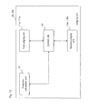
- Fig. 11 is a diagram showing the function blocks of the face detection device 4a.
- the face detection device 4a comprises an input unit 5, an output unit 6, a LUT storage unit 7a, a judgment unit 8a and a setting storage unit 9, in which the various programs (OS, application program, etc.) stored in the auxiliary storage unit are loaded on the main storage unit and executed by the CPU.
- each function unit of the face detection device 4a is explained.
- the input unit 5 functions as an interface for inputting the data on an original human image (hereinafter referred to as "the original image data") to the face detection device 4a.
- the original image data may be the data of a still image or the data of a dynamic image.
- the original image data is input to the face detection device 4a from outside the face detection device 4a by the input unit 5.
- the input unit 5 may be configured using any existing technique to input the original image data to the face detection device 4a.
- the original image data may be input to the face detection device 4a through a network (local area network, internet, etc.).
- the input unit 5 is configured of a network interface.
- the original image data may be input to the face detection device 4a from a digital camera, a scanner, a personal computer or a recording device (such as a hard disk drive).
- the input unit 5 is configured in conformance with a standard (the standard for the wire connection such as USB (Universal Serial Bus) or SCSI (Small Computer System Interface) or the radio connection such as Bluetooth) which can establish communication between the face detection device 4a and the digital camera, the personal computer or the recording device.
- a standard the standard for the wire connection such as USB (Universal Serial Bus) or SCSI (Small Computer System Interface) or the radio connection such as Bluetooth
- the original image data recorded in a recording medium may be input to the face detection device 4a.
- the input unit 5 is configured of a device (such as the flash memory reader, the floppy disk drive, the CD drive or the DVD drive) for reading the data from the recording medium.
- the face detection device 4a may be included in an image pickup device such as a digital camera or any of various devices (for example, a PDA (personal digital assistant) having an image pickup device such as a digital camera or a portable telephone, so that a human image picked up may be input to the face detection device 4a as an original image data.
- the input unit 5 may be configured of a CCD (charge coupled device) or a CMOS (complementary metal-oxide semiconductor) sensor, or as an interface for inputting the original image data picked up by the CCD or the CMOS sensor to the face detection device 4a.
- CCD charge coupled device
- CMOS complementary metal-oxide semiconductor
- the face detection device 4a may be included in an image output device such as a printer or a display so that a human image input to the image output device as an output data may be input to the face detection device 4a as an original image data.
- the input unit 5 is configured of a device for converting the original image data input to the image output device into a data that can be handled by the face detection device 4a.
- the input unit 5 may be so configured as to respond to a plurality of events.
- the output unit 6 functions as an interface whereby the data indicating whether a human face is detected by the judgment unit 8a and/or the data indicating the position and size of the detected face is output externally of the face detection device 4a.
- the output unit 6 may be configured using any existing technique for outputting the data on the human face detection result from the face detection device 4a.
- the data on the detection result may be output from the face detection device 4a through a network, for example.
- the output unit 6 is configured of a network interface.
- the data on the detection result may be output to another information processing system such as a personal computer or a recording unit.
- the output unit 6 is configured in conformance with the standard for connecting another information processing system such as a personal computer or a recording device and the face detection device 4a to each other in a communicable way.
- the data on the detection result may be output to (written in) a recording medium.
- the output unit 6 is configured of a device (such as a flash memory writer, a floppy disk drive, a CD-R drive or a DVD-R drive) for writing the data into the recording device or the recording medium, as the case may be.
- a device such as a flash memory writer, a floppy disk drive, a CD-R drive or a DVD-R drive
- the data output from the output unit 6 may be used.
- the output unit 6 may be configured either as an interface for data communication with the display unit or as an interface for delivering the data to an information processing system connected to or built in the display unit.
- the digital camera may be configured to control the focal point or the image pickup operation including the exposure correction based on the data output from the output unit 6.
- the output unit 6 may be configured as an interface capable of data communication with, for example, the information processing system in the digital camera.
- the information processing system may be configured to determine the area and specifics of the image correcting process based on the data output from the output unit 6.
- the output unit 6 may be configured as an interface capable of data communication with the particular information processing system or the device included therein.
- the output unit 6 may be configured to be capable of responding to a plurality of the events described above.
- the LUT storage unit 7a is configured of a nonvolatile memory.
- the LUT storage unit 7a stores the LUT 19a used by the judging unit 8a to execute the face detection process. Specifically, the LUT storage unit 7a stores the LUT 19a for the face rectangle 1 of each pattern obtained as the result of the learning process.
- the LUT storage unit 7a therefore, may be able to store a plurality of LUTs 19a.
- the judging unit 8a executes the face detection process based on the setting stored in the setting storage unit 9 using the LUT 19a stored in the LUT storage unit 7a.
- the judging unit 8a delivers the result of execution of the face detection process to the output unit 6.
- the judging unit 8a inputs the data to and outputs the data from the input unit 5, the output unit 6, the LUT storage unit 7a and the setting storage unit 9 through an input device and an output device not shown.
- the judging unit 8a is realized by a CPU executing a face detection program. Also, the judging unit 8a may be configured as a dedicated chip.
- Fig. 12 is a diagram showing the internal function blocks of the judging unit 8a. With reference to Fig. 12 , the function blocks of the judging unit 8a are explained.
- the judging unit 8a includes a feature calculation unit 10, a first judging unit 11a, a control unit 12 and a second judging unit 13a.
- the feature calculation unit 10 calculates the features of the first feature area and the second feature area in each layer.
- the feature calculation unit 10 calculates a relative value (a differential value in the case under consideration) of the two features thus calculated.
- the first judging unit 11a acquires a judgment value corresponding to the differential value calculated by the feature calculation unit 10, and based on at least one judgment value, judges whether a human face is included in an intended area. Specifically, the first judging unit 11a reads the LUT 19a corresponding to the pattern used for calculation of the feature by the feature calculation unit 10. The first judging unit 11a, based on the LUT 19a thus read, acquires the judgment value corresponding to the differential value calculated by the feature calculation unit 10. The first judging unit 11a acquires the judgment values corresponding to all the patterns assigned to each layer, calculates the total number of points in each layer based on the judgment values and judges whether a human face is included in the intended area (S03 and S04 in Fig. 3 ).
- the control unit 12 reads the various settings stored in the setting storage unit 9, and applies the position and size of the first rectangle 2 and the second rectangle 3 of each pattern to the feature calculation unit 10. Also, the control unit 12 applies each feature calculated by the feature calculation unit 10 and the LUT 19a corresponding to the pattern used for calculation of the particular feature to the first judging unit 11a. The control unit 12 also applies the judgment result of the first judging unit 11a to the second judging unit 13a. Further, the control unit 12 selects an intended area (S01 in Fig. 3 ) and controls the operation of the judging unit 8a (S02, S05 and S07 in Fig. 3 ).
- the second judging unit 13a based on the result produced by the first judging unit 11a, i.e. based on the judgment result in each layer, finally judges whether the currently intended area includes a face or not (S06 in Fig. 3 ).
- the setting storage unit 9 is configured of a nonvolatile memory.
- the setting storage unit 9 stores various settings used by the judging unit 8a to execute the face detection process.
- the setting storage unit 9 stores, for example, the face rectangle 1 of each pattern. Specifically, the position and size of the first rectangle 2 and the second rectangle 3 of each pattern are stored. Also, the setting storage unit 9 stores which pattern of the face rectangle 1 is assigned to each layer. Further, the setting storage unit 9 stores a method of selecting an intended area from within a human image.
- the table generating device 14a includes, in terms of hardware, a CPU (central processing unit), a main storage unit (RAM) and an auxiliary storage unit connected to each other through a bus.
- the auxiliary storage unit is configured of a nonvolatile memory.
- Fig. 13 is a diagram showing the function blocks of the table generating device 14a.
- the table generating device 14a includes a feature calculation unit 15, a frequency acquisition unit 16, a judging unit 17a and a table generating unit 18a, in which various programs (OS, application program, etc.) stored in the auxiliary storage unit are loaded onto the main storage unit and executed by the CPU.
- various programs OS, application program, etc.
- the table generating unit 14a generally executes the learning process after a change. Now, each functional part of the table generating device 14a is explained with reference to Fig. 13 .
- the feature calculation unit 15 calculates the features of the first feature area and the second feature area in accordance with a pattern of each sample image.
- the feature calculation unit 15 calculates the differential value as a relative value of each feature.
- the features of each pattern (size, position, etc. of each feature area) may be stored either in the feature calculation unit 15 or in other functional parts not shown.
- the frequency acquisition unit 16 acquires a success distribution and a failure distribution based on the result of calculation in the feature calculation unit 15.
- the frequency acquisition unit 16 acquires the frequency of each section of the success distribution and the failure distribution.
- the judging unit 17a determines the judgment value of each section based on the frequency in each section of the success distribution and the failure distribution acquired by the frequency acquisition unit 16.
- the table generating unit 18a generates the LUT 19a showing the correspondence between the judgment value determined by the judging unit 17a and the section thereof. Also, the table generating unit 18a judges which LUT 19a is to be used in the face detection device 4a, by executing the boosting learning algorithm, and assigns it to each layer.
- the LUT 19a but not the threshold value is used to execute the judgment process in each layer of the face detection process based on the face rectangle 1 of each pattern.
- This LUT 19a holds in it the range of the differential value of the features in each feature area and the judgment value corresponding to each range of the differential value. Based on this judgment value, the judgment for each pattern is executed.
- the face detection device 4a As compared with a case in which the presence or absence of a face in an intended area is judged based on a given threshold value, therefore, a more accurate judgment is made possible using the face rectangle 1 of each pattern.
- a histogram as shown in Fig. 9 is obtained by learning, for example, the prior art in which a simple distribution is assumed is such that the boundary between the fourth and fifth sections from the left side is set as a threshold value. Specifically, no specific consideration is given to the distribution having small peaks (the second and third sections from the right in Fig. 9 ).
- the face detection device 4a even the distribution having small peaks is also considered for judgment independently by use of the LUT 19a.
- the face detection device 4a using the face rectangle 1 of each pattern carries out individual judgments more accurately than in the prior art.
- the number of patterns of the face rectangle 1 assigned to each layer is reduced and/or the number of layers executed in the face detection process is reduced. Specifically, the total number of patterns of the face rectangle 1 on which judgment is carried out is reduced in the face detection process for one intended area.
- the reason by which the judgment is made based on a plurality of patterns of the face rectangle 1 in the face detection process with the face detection technique used for the face detection device 4a is the fact that the judgment based on the face rectangle 1 of each pattern is very inaccurate. Specifically, the judgment on the individual basis should be inaccurate, and therefore the accuracy would be required to be improved by the judgment based on multiple patterns of the face rectangle 1. In the face detection device 4a, however, the accuracy of the judgment based on the individual pattern of the face rectangle 1 is improved. Therefore, the total number of patterns of the face rectangle 1 used for the face detection process for each intended area can be reduced, thereby making it possible to increase the processing speed without adversely affecting the overall accuracy of the face detection process.
- the face detection device 4a for detecting a human face in an image is explained above taking a specified object detection apparatus as a specific example.
- Other specific examples of the specified object detection apparatus include a device for detecting the body of an automobile from an image, a device for detecting a specified animal such as a cat or a dog and a device for detecting a specified character, symbol or logo. These devices have a basic configuration similar to that of the face detection device 4a, the only difference being in the sample image used for the learning process. Also, in accordance with each specified object to be detected, the face detection device 4a may be appropriately altered.
- a relative value such as the ratio of each feature may be used.
- the abscissa of the histogram ( Fig. 9 ) is segmented into sections at specified intervals, after which each section is assigned a judgment value of "0" or "1".
- each section is assigned a judgment value in real number.
- Fig. 15 is a diagram showing an example of the judgment value assigned to each section of the histogram according to the second embodiment.
- the judgment value indicates the degree of the probability or the very probability that the image distributed in the section of the corresponding differential value is a face image.
- the judgment value in the first embodiment indicates "whether the possibility that the image in the intended area is a face is high or not", while the judgment value in the second embodiment indicates “the degree of possibility that the image in the intended area is a face".
- the judgment value assumes a real number of "0" to "1". The higher this value, the higher the probability that the image in the intended area is a face image. More specifically, the judgment value may be calculated based on Equation 1 below. In Equation 1 below, the judgment value is calculated as h(x).
- this judgment value may be determined based on the difference or the ratio between the frequency of the success distribution and the frequency of the failure distribution. In this case, the higher the frequency of the success distribution with respect to the frequency of the failure distribution, the larger the judgment value, and vice versa.
- the LUT 19b is produced based on the judgment value in each section of this histogram.
- Fig. 16 is a diagram showing an example of the LUT 19b.
- the LUT 19b has a judgment value corresponding to each section of the differential value which is expressed as a real number.
- the LUT 19b is produced which corresponds to each of the face rectangles 1 of all the patterns.
- the LUT 19b is assigned to each of a plurality of layers.
- each layer (except for the layer to execute the first process) executes a different process from the corresponding layer in the first embodiment.
- Fig. 17 is a diagram showing the outline of the process executed in each layer according to the second embodiment.
- the first layer (Layer 1), like each layer in the first embodiment, acquires the judgment value of each pattern assigned to the particular layer.
- the layer 1 calculates the total number of points of the layer based on the judgment value of each pattern and judges whether a face exists or not in the intended area.
- each layer is different from the corresponding layer in the first embodiment in that in the second embodiment, the total number of points for a given layer is calculated taking into account the total number of points for the immediately preceding layer.
- Each layer in the second embodiment regards the judgment value of each pattern as the number of points of the particular pattern. Nevertheless, a configuration can alternatively be employed in which another value obtained from the judgment value of each pattern is treated as the number of points of the particular pattern.
- Fig. 18 is a diagram showing a specific example of the process executed in each layer according to the second embodiment.
- the layer m (which is not the first layer to execute the process) calculates the feature based on each pattern assigned to the layer m. Then, the layer m acquires the judgment values (pt2 to ptn) based on the LUT 19b and the feature calculated for each pattern. Further, the layer m acquires the total number of points in the immediately preceding layer (layer m-1) with the judgment value pt1.
- the total number of points in each layer is calculated taking into consideration only the number of points of the patterns having the judgment value of "1".
- each layer calculates the total number of points taking the judgment values in real number of all the patterns.
- the layer m calculates the total number of points based on all the judgment values (pt1 to ptn) and thus executes the judgment as layer m.
- the layer m upon judgment that a face is included in the intended area, delivers the total number of points in the layer m to the next layer (layer m+1). In the last layer, it is judged finally whether a face exists or not in the intended area.
- the configuration of the face detection device 4b according to the second embodiment is explained.
- the face detection device 4b is different from the face detection device 4a in that the face detection device 4b includes a LUT storage unit 7b and a judging unit 8b in place of the LUT storage unit 7a and the judging unit 8a, respectively.
- the difference of the face detection device 4b from the face detection device 4a is explained below.
- the LUT storage unit 7b is different from the LUT storage unit 7a in that the LUT storage unit 7b stores the LUT 19b ( Fig. 16 ) in place of the LUT 19a ( Fig. 10 ). In other points, the LUT storage unit 7b has a similar configuration to the LUT storage unit 7a.
- the judging unit 8b executes the face detection process based on the setting stored in the setting storage unit 9 using the LUT 19b stored in the LUT storage unit 7b. Now, the function blocks of the judging unit 8b are explained with reference to Fig. 12 .
- the judging unit 8b is different from the judging unit 8a in that the first judging unit 11a is replaced by the first judging unit 11b and the second judging unit 13a is replaced by the second judging unit 13b.
- the difference of the judging unit 8b from the judging unit 8a is explained below.
- the first judging unit 11b acquires the judgment value corresponding to the differential value calculated by the feature calculation unit 10, and based on at least one judgment value, judges whether a human face is included in the intended area or not. Specifically, the first judging unit 11b reads the LUT 19b corresponding to the pattern used for calculation of the feature by the feature calculation unit 10. The first judging unit 11b, based on the LUT 19b thus read, acquires the judgment value in real number corresponding to the differential value calculated by the feature calculation unit 10, i.e. the judgment value for each pattern. The first judging unit 11b, based on these judgment values, calculates the total number of points for each layer and judges whether a human face is included in the intended area or not.
- the first judging unit 11b uses a value based on the total number of points in the immediately preceding layer as one of the judgment values. Specifically, in each of the second and subsequent layers, the first judging unit 11b calculates the total number of points for the particular layer using the value based on the total number of points in the immediately preceding layer and all the judgment values corresponding to the patterns assigned to the particular layer. In accordance with the total number of points thus calculated, the first judging unit 11b judges, for the particular layer, whether a face is included or not in the currently intended object.
- the second judging unit 13b based on the result of the process executed in the first judging unit 11b, i.e. based on the judgment result in each layer, finally judges whether a face is included or not in the currently intended area (S06 in Fig. 3 ).
- the table generating device 14b is different from the table generating device 14a in that the table generating device 14b executes the learning process according to the second embodiment. Specifically, the table generating device 14b is different from the table generating device 4a in that the judging unit 17a and the table generating unit 18a are replaced with the judging unit 17b and the table generating unit 18b, respectively. Only the difference of the table generating device 14b from the table generating device 14a is described below.
- the judging unit 17b calculates the judgment value in real number of each section in accordance with Equation 1.
- the table generating unit 18b generates the LUT 19b containing the judgment values in real number calculated by the judging unit 17b and the corresponding sections. Also, the table generating unit 18b judges which LUT 19b is to be used for the face detection device 4b by executing the boosting learning algorithm, and assigns the LUT 19b thus selected to each layer.
- the judgment based on the face rectangle 1 of each pattern uses the LUT 19b ( Fig. 16 ) but not the LUT 19a.
- the LUT 19b holds therein the values of "0" to "1” in real number but not the binary digit "0" or "1” as a judgment value corresponding to each range of the differential value.
- the accuracy of the process for each layer is improved as compared with the face detection device 4a for executing the process using the LUT 19a.
- the LUT 19a a case in which there is substantially no frequency difference between the success distribution and the failure distribution and the judgment value is determined as "0" with a slight margin (hereinafter called the case 1) is handled exactly the same way as a case in which the frequency of the failure distribution is apparently overwhelmingly large and the judgment value is determined as "0" (hereinafter called the case 2).
- the judgment value is determined as, for example, "0.4" in the case 1 and "0.1” in the case 2, which are considered differently. Therefore, the case 1 frequent and the case 2 frequent can be considered as different situations (different numbers of points), thereby contributing to an improved accuracy of face detection.
- the judgment value of each pattern is expressed in real number for an improved accuracy, and therefore the number of patterns assigned to each layer is reduced while at the same time maintaining the processing accuracy.
- the judging process can be executed with a fewer number of patterns than in the prior art. As a result, the processing speed is improved. For the same reason, the number of layers is reduced for an improved processing speed.
- the number of points in a layer for which the judging process has been completed is used in a layer for which the judging process has yet to be completed thereby to execute the judging process in the latter layer.
- the judgment value of each pattern in a layer for which the judging process is already completed is reflected in the judging process executed in subsequent layers.
- the number of patterns affecting the judging process is virtually increased as compared with the number of patterns actually used.
- the accuracy of the judging process for each layer can be improved.
- the number of patterns assigned to each layer can be reduced and a higher processing speed can be realized while at the same time maintaining the accuracy of the judging process.
- the number of layers can be reduced to realize a high processing speed.
- a reduced number of patterns can reduce the number of resources used in the face detection device 4b.
- the judgment value is expressed in a fraction down to the first decimal place with one significant digit. Nevertheless, the judgment value is not necessarily expressed in this way. Specifically, the designer can freely determine to his/her convenience the significant number of digits and the decimal place down to which the judgment value should be expressed.
- the second judging unit 13b may be configured to calculate the total number of points in each layer not using all the judgment values corresponding to each pattern assigned to the particular layer but using only the judgment values exceeding a threshold value ("0.2" or "0.5", for example) of all the judgment values corresponding to each pattern assigned to the particular layer.
- the second judging unit 13b may be also so configured as to calculate the total number of points in each layer not using the total number of points in the immediately preceding layer but using a value based on the total number of points in one or more layers for which the judgment process is executed before the immediately preceding layer.
- the second judging unit 13b in obtaining a judgment value using the total number of points in one or more layers for which the judging process is previously processed, may either use the total number of points directly as a judgment value or add some weight to the total number of points.
Landscapes
- Engineering & Computer Science (AREA)
- Theoretical Computer Science (AREA)
- General Physics & Mathematics (AREA)
- Physics & Mathematics (AREA)
- General Health & Medical Sciences (AREA)
- Multimedia (AREA)
- Health & Medical Sciences (AREA)
- Evolutionary Computation (AREA)
- Computer Vision & Pattern Recognition (AREA)
- Artificial Intelligence (AREA)
- Data Mining & Analysis (AREA)
- Computing Systems (AREA)
- Databases & Information Systems (AREA)
- Software Systems (AREA)
- Oral & Maxillofacial Surgery (AREA)
- Human Computer Interaction (AREA)
- Medical Informatics (AREA)
- Life Sciences & Earth Sciences (AREA)
- Bioinformatics & Cheminformatics (AREA)
- Bioinformatics & Computational Biology (AREA)
- Evolutionary Biology (AREA)
- General Engineering & Computer Science (AREA)
- Image Analysis (AREA)
- Image Processing (AREA)
- Burglar Alarm Systems (AREA)
- Ultra Sonic Daignosis Equipment (AREA)
Claims (11)
- Vorrichtung zum Erfassen eines spezifizierten Objekts, wobei die Vorrichtung umfasst:eine Speichereinheit (7a, 7b) zum Speichern jedes Beurteilungswerts, der in Übereinstimmung mit jedem einer Mehrzahl von Rechteckmustern (1) vorbereitetet wurde, wobei ein Beurteilungswert die Möglichkeit repräsentiert, dass das spezifizierte Objekt in einem beabsichtigten Bereich enthalten ist;
eine Recheneinheit (10), die eine Mehrzahl von Schichten, jede Schicht zum Berechnen von Merkmalen verschiedener Muster in einem selben beabsichtigten Bereich aus einem Bild durch Rechenprozesse, die jeweils jedem Muster entsprechen, umfasst; und
eine erste Beurteilungseinheit (11a, 11b) zum Ausgeben eines Beurteilungsergebnisses, ob ein spezifiziertes Objekt in dem beabsichtigten Bereich enthalten ist, auf der Grundlage der in der Speichereinheit (7a, 7b) gespeicherten Beurteilungswerte und entsprechend den durch die Recheneinheit (10) berechneten Merkmalen, und
eine Steuereinheit zum Anlegen einer Mehrzahl von Mustern als einer Menge, die durch eine Mehrzahl verschiedener Rechenprozesse erhalten wird, die jeweils durch eine Schicht der Recheneinheit (10) ausgeführt werden, an die erste Beurteilungseinheit (11a, 11b), um dadurch die Beurteilungsergebnisse in der Anzahl zu erfassen, die ausreicht, um von der ersten Beurteilungseinheit (11a, 11 b) eine endgültige Beurteilung zu erhalten; und
eine zweite Beurteilungseinheit (13a, 13b), um auf der Grundlage einer Mehrzahl von Ergebnissen der Beurteilung, die durch die erste Beurteilungseinheit (11a, 11b) vorgenommen und durch das Steuerteil erfasst werden, endgültig zu beurteilen, ob ein spezifiziertes Objekt in dem beabsichtigten Bereich enthalten ist,dadurch gekennzeichnet, dass:- die erste Speichereinheit (7a, 7b) ferner eine Anzahl von jedem Rechteckmuster (1) zugeordneten Punkten speichert,- die erste Beurteilungseinheit (11a, 11b) ferner für jede Schicht auf der Grundlage der in der Speichereinheit (7a, 7b) gespeicherten Beurteilungswerte und entsprechend den durch die Recheneinheit (10) berechneten Merkmalen eine Gesamtzahl von Punkten berechnet, wobei die Gesamtzahl von Punkten auf der Anzahl von Punkten, die jedem Muster der Schicht zugeordnet sind, für das die Beurteilung lautet, dass das spezifizierte Objekt in dem beabsichtigten Bereich enthalten ist, und für jede der zweiten und nachfolgenden Schichten auf der Gesamtzahl von Punkten in der unmittelbar vorherigen Schicht beruht, wobei das Beurteilungsergebnis der Schicht repräsentiert, ob ein spezifiziertes Objekt in dem beabsichtigten Bereich, der auf dieser Gesamtzahl von Punkten beruht, enthalten ist,- wobei die erste Beurteilungseinheit (11a, 11b) die Mehrzahl der Ergebnisse der Beurteilungen, ob ein spezifiziertes Objekt in dem beabsichtigten Bereich enthalten ist, liefert. - Vorrichtung zum Erfassen eines spezifizierten Objekts zum Erfassen eines spezifizierten Objekts in einem Bild nach Anspruch 1, dadurch gekennzeichnet, dass
die Speichereinheit (7a, 7b) ferner Lerndaten in Form einer Nachschlagetabelle (bzw. in Form von Nachschlagetabellen) (19a, 19b) speichert. - Vorrichtung zum Erfassen eines spezifizierten Objekts nach Anspruch 2, bei der:die Recheneinheit (10) zum Berechnen von Differenzwerten zwischen den Merkmalswerten eines ersten Merkmalsbereichs (2) und eines zweiten Merkmals (3) für ein zweites und für zusätzliche Muster desselben beabsichtigten Bereichs (1) dient; und wobeidie erste Beurteilungseinheit (11a, 11b) zum Berechnen einer Anzahl von Punkten auf der Grundlage der Beurteilung reeller Werte der in der Speichereinheit (7a, 7b) gespeicherten Nachschlagetabellen (19b) und entsprechend den durch die Recheneinheit (10) berechneten Merkmalen und zum Beurteilen auf der Grundlage dieser Anzahl von Punkten, ob ein spezifiziertes Objekt in dem beabsichtigten Bereich (1) enthalten ist, dient;die Steuereinheit (12) zum Anlegen einer Mehrzahl von Merkmalen als einer Menge, die durch eine Mehrzahl verschiedener durch die Recheneinheit (10) ausgeführter Rechenprozesse erhalten wird, an die erste Beurteilungseinheit und dadurch zum Erfassen der Beurteilungsergebnisse in einer ausreichenden Anzahl zum Erhalten einer endgültigen Beurteilung von der ersten Beurteilungseinheit (11a, 11b) dient; unddie zweite Beurteilungseinheit (13a, 13b) zum endgültigen Beurteilen, ob ein spezifiziertes Objekt in dem beabsichtigten Bereich (1) enthalten ist, auf der Grundlage einer Mehrzahl von Ergebnissen der Beurteilung, die durch die erste Beurteilungseinheit (11a, 11b) vorgenommen und durch die Steuereinheit erfasst wird, dient.
- Vorrichtung zum Erfassen eines spezifizierten Objekts zum Erfassen eines spezifizierten Objekts in einem Bild nach Anspruch 2 oder 3, wobei die Vorrichtung ferner umfasst:- eine Eingabeeinheit (5) zum Eingeben von Daten des Bilds,- eine Einstellungsspeichereinheit (9) zum Speichern verschiedener Einstellungsdaten über die beabsichtigten Bereiche und über die in jedem beabsichtigten Bereich enthaltenen Muster, wobei die Beurteilungseinheit (8a) von der Eingabeeinheit (5) Daten über das Bild empfängt,- ein Ausgabeeinheit (6), die von der Beurteilungseinheit (8a) wenigstens eine Dateneinheit empfängt, um anzugeben, ob durch die Beurteilungseinheit (8a, 8b) ein spezifiziertes Objekt erfasst wird, und/oder um die Daten anzugeben, die die Position und die Größe des erfassten spezifizierten Objekts angeben.
- Vorrichtung zum Erfassen eines spezifizierten Objekts nach Anspruch 4, bei der die Merkmalsberechnungseinheit (10) mehrere Schichten enthält, wobei jede Schicht die Merkmale eines ersten Merkmalsbereichs (2) und eines zweiten Merkmalsbereichs (3) eines der bestimmten Schicht zugeordneten bestimmten Musters und einen relativen Wert davon berechnet, und bei der die Einstellungsspeichereinheit (9) ferner, welches bestimmte Muster einer bestimmten Schicht der Merkmalsberechnungseinheit (10) zugeordnet ist, und in der Einstellungsspeichereinheit (9) gespeicherte durch die Steuereinheit (12) resultierende Einstellungen, die für die Merkmalsberechnungseinheit (10) die Position und die Größe des ersten Merkmalsbereichs (2) und des zweiten Merkmalsbereichs (3) eines bestimmten Musters angeben, und außerdem die Nachschlagetabelle (19a, 19b), die unter Verwendung desselben bestimmten Musters erhalten wurde und die zum Beurteilen und Senden der Beurteilung an die zweite Beurteilungseinheit (13a, 13b) verwendet werden soll, speichert,
wobei die erste Beurteilungseinheit (11a) auf der Grundlage des durch die Merkmalsberechnungseinheit (10) berechneten relativen Werts und auf der Grundlage der durch die Steuereinheit (12) für das Muster angegebenen Nachschlagetabelle (19a, 19b) einen Beurteilungswert darüber erfasst, ob ein spezifiziertes Objekt in dem beabsichtigten Bereich enthalten ist,
wobei die zweite Beurteilungseinheit (13a) auf der Grundlage des Beurteilungsergebnisses in jeder Schicht beurteilt, ob ein spezifiziertes Objekt in dem beabsichtigten Bereich enthalten ist. - Verfahren zur Erfassung eines spezifizierten Objekts in einem beabsichtigten Bereich eines Bilds, wobei das Verfahren umfasst:a) Vorbereiten von Beurteilungswerten in Übereinstimmung mit jedem einer Mehrzahl von Rechteckmustern und ihr Speichern, wobei jeder Beurteilungswert die Möglichkeit repräsentiert, dass das spezifizierte Objekt in einem beabsichtigten Bereich enthalten ist;b) Berechnen von Merkmalen verschiedener Muster in einem selben beabsichtigten Bereich aus einem Bild durch Rechenprozesse, die jeweils jedem Muster entsprechen, in einer Recheneinheit (10), die eine Mehrzahl von Schichten umfasst; undc) Beurteilen (S03), ob das spezifizierte Objekt in dem beabsichtigten Bereich enthalten ist oder nicht, auf der Grundlage der gespeicherten Beurteilungswerte und entsprechend den in Schritt b) berechneten Merkmalen,d) erneutes Ausführen der Schritte b) und c) unter Verwendung einer Mehrzahl von Mustern als einer durch eine Mehrzahl verschiedener Rechenprozesse, die jeweils durch eine Schicht der Recheneinheit (10) ausgeführt werden, erhaltenen Menge, um dadurch die Beurteilungsergebnisse in der Anzahl zu erfassen, die ausreicht, um eine endgültige Beurteilung zu erhalten, und jedes Mal Speichern der somit erhaltenen Beurteilungen,e) endgültiges Beurteilen, ob ein spezifiziertes Objekt in dem beabsichtigten Bereich enthalten ist, auf der Grundlage einer Mehrzahl von Ergebnissen der in Schritt d) vorgenommenen und gespeicherten Beurteilung,
dadurch gekennzeichnet, dass
jedem Rechteckmuster (1) eine Anzahl von Punkten zugeordnet und gespeichert wird,
in Schritt c) ferner für jede Schicht eine Gesamtzahl von Punkten berechnet wird, wobei die Gesamtzahl von Punkten auf der Anzahl von Punkten, die jedem Muster der Schicht zugeordnet wird, für das die Beurteilung lautet, dass das spezifizierte Objekt in dem beabsichtigten Bereich enthalten ist, und für jede der zweiten und nachfolgenden Schichten auf der Gesamtzahl von Punkten in der unmittelbar vorherigen Schicht beruht,
in Schritt d) das Bilden des Beurteilungsergebnisses der Schicht, ob ein spezifiziertes Objekt in dem beabsichtigten Bereich enthalten ist, ferner auf der Gesamtzahl von Punkten der Schicht beruht. - Verfahren zur Erfassung eines spezifizierten Objekts in einem Bild nach Anspruch 6, wobei das Verfahren ferner umfasst:g) erneutes Ausführen der Schritte b), c), d) und e) jedes Mal für einen anderen beabsichtigten Bereich des Bilds und Beurteilen, ob das spezifizierte Objekt in dem Bild enthalten ist, gemäß den in den verschiedenen beabsichtigten Bereichen des Bilds erhaltenen Ergebnissen.
- Verfahren zur Erfassung eines spezifizierten Objekts in einem beabsichtigten Bereich eines Bilds nach Anspruch 6, dadurch gekennzeichnet, dass in Schritt a) die vorbereitete und gespeicherte Beurteilung die Form einer Nachschlagetabelle aufweist, die durch ein Verfahren geliefert wird, das umfasst:- aa) Einreichen einer Menge von Probenobjektbildern und Nichtprobenobjektbildern an die Vorrichtung,- ab) Berechnen eines Differenzwerts zwischen den Merkmalswerten eines ersten Merkmalsbereichs (2) und eines zweiten Merkmalsbereichs (3) für ein erstes Muster eines beabsichtigten Bereichs (1), und wobei es ferner umfasst:- ac) Zeichnen einer Kurve, die für das erste Muster in der Abszisse berechnete relative Werte und in der positiven Ordinate eine Häufigkeit, in der jeder Differenzwert für das Objektbild erscheint, aufweist,wobei die Kurve eine positive Ordinate, die eine Erfolgsverteilungskurve ist, und in der negativen Ordinate eine Häufigkeit, mit der jeder Wert für das Nichtobjektbild erscheint, aufweist, wobei die Kurve in der negativen Ordinate eine Ausfallverteilungskurve ist,- ad) Segmentieren der Abszisse bei verschiedenen spezifizierten Intervallen,- ae) für jedes Intervall Bestimmen eines positiven Beurteilungswerts für die Intervalle mit einer hohen Wahrscheinlichkeit, ein Objektbild zu sein, wobei in den Intervallen die Häufigkeit des Erfolgs höher als die Häufigkeit des Ausfalls ist, und eines negativen Beurteilungswerts für die Intervalle mit einer niedrigen Wahrscheinlichkeit, ein Objektbild zu sein, wobei in den Intervallen die Häufigkeit des Erfolgs niedriger als die Häufigkeit der Ausfälle ist,
Aufbauen einer Nachschlagetabelle (19a, 19b), in der die positive oder die negative Beurteilung für jedes spezifizierte Intervall der Abszisse vorgenommen wird, und- af) Speichern der Nachschlagetabelle (19a, 19b). - Verfahren zur Erfassung eines spezifizierten Objekts in einem beabsichtigten Bereich eines Bilds nach Anspruch 8, in dem
die Schritte a) bis e) für die Menge des Probenobjektbilds und des Nichtprobenobjektbilds (n-1)-mal erneut ausgeführt werden, wobei jedes Mal mit einem zweiten, einem dritten und bis zu einem n-ten Muster erfolgt, um für jedes der (n-1) Muster eine Nachschlagetabelle (19a, 19b) zu erzeugen. - Verfahren zur Erfassung eines spezifizierten Objekts in einem beabsichtigten Bereich eines Bilds nach Anspruch 8 oder 9, in dem der positive Beurteilungswert 1 ist und der negative Beurteilungswert 0 ist.
- Verfahren zur Erfassung eines spezifizierten Objekts in einem beabsichtigten Bereich eines Bilds nach Anspruch 8 oder Anspruch 9, in dem der positive Beurteilungswert ein reeller Wert ist, der der Häufigkeit des Erfolgs entspricht, und der negative Beurteilungswert eine Häufigkeit ist, die der Häufigkeit eines Ausfalls entspricht.
Applications Claiming Priority (2)
| Application Number | Priority Date | Filing Date | Title |
|---|---|---|---|
| CNB2004100381936A CN100405388C (zh) | 2004-05-14 | 2004-05-14 | 特定被摄体检测装置 |
| CN200410038193 | 2004-05-14 |
Publications (2)
| Publication Number | Publication Date |
|---|---|
| EP1596323A1 EP1596323A1 (de) | 2005-11-16 |
| EP1596323B1 true EP1596323B1 (de) | 2008-11-05 |
Family
ID=34929988
Family Applications (1)
| Application Number | Title | Priority Date | Filing Date |
|---|---|---|---|
| EP04106272A Expired - Lifetime EP1596323B1 (de) | 2004-05-14 | 2004-12-03 | Anordnung zur Erkennung bestimmter Objekte |
Country Status (6)
| Country | Link |
|---|---|
| US (1) | US7457432B2 (de) |
| EP (1) | EP1596323B1 (de) |
| JP (1) | JP4459795B2 (de) |
| CN (1) | CN100405388C (de) |
| AT (1) | ATE413660T1 (de) |
| DE (1) | DE602004017576D1 (de) |
Cited By (1)
| Publication number | Priority date | Publication date | Assignee | Title |
|---|---|---|---|---|
| US8170332B2 (en) | 2009-10-07 | 2012-05-01 | Seiko Epson Corporation | Automatic red-eye object classification in digital images using a boosting-based framework |
Families Citing this family (28)
| Publication number | Priority date | Publication date | Assignee | Title |
|---|---|---|---|---|
| JP2007094633A (ja) * | 2005-09-28 | 2007-04-12 | Fujifilm Corp | 顔検出装置ならびにプログラム |
| DE102006012477A1 (de) * | 2006-03-16 | 2007-09-20 | Robert Bosch Gmbh | Bewertungsvorrichtung, Verfahren und Computerprogramm |
| JP2007274017A (ja) * | 2006-03-30 | 2007-10-18 | Fujifilm Corp | 自動トリミング方法および装置ならびにプログラム |
| JP4839952B2 (ja) | 2006-05-01 | 2011-12-21 | ソニー株式会社 | 画像処理装置および方法、並びにプログラム |
| WO2008044524A1 (fr) * | 2006-10-10 | 2008-04-17 | Nikon Corporation | Programme de classification d'image, appareil de classification d'image et caméra électronique |
| JP4582079B2 (ja) * | 2006-10-19 | 2010-11-17 | トヨタ自動車株式会社 | 画像識別装置および画像識別方法 |
| KR101330636B1 (ko) * | 2007-01-24 | 2013-11-18 | 삼성전자주식회사 | 얼굴시점 결정장치 및 방법과 이를 채용하는 얼굴검출장치및 방법 |
| JP5009172B2 (ja) * | 2007-03-20 | 2012-08-22 | 株式会社リコー | 画像処理装置、撮像装置、画像処理方法、顔検出プログラムおよび記録媒体 |
| US8363909B2 (en) * | 2007-03-20 | 2013-01-29 | Ricoh Company, Limited | Image processing apparatus, image processing method, and computer program product |
| EP2151801B1 (de) * | 2008-04-11 | 2016-05-11 | Panasonic Intellectual Property Corporation of America | Bildbearbeitungsvorrichtung, sowie verfahren und speichermedium dafür |
| JP5132445B2 (ja) * | 2008-06-25 | 2013-01-30 | キヤノン株式会社 | 画像処理装置および画像処理方法並びにコンピュータプログラムおよび記憶媒体 |
| CN101477625B (zh) * | 2009-01-07 | 2013-04-24 | 北京中星微电子有限公司 | 人体上半身检测方法和系统 |
| JP2010170184A (ja) * | 2009-01-20 | 2010-08-05 | Seiko Epson Corp | 顔画像における特徴部位の位置の特定 |
| US9293017B2 (en) * | 2009-02-26 | 2016-03-22 | Tko Enterprises, Inc. | Image processing sensor systems |
| US9740921B2 (en) | 2009-02-26 | 2017-08-22 | Tko Enterprises, Inc. | Image processing sensor systems |
| US9277878B2 (en) | 2009-02-26 | 2016-03-08 | Tko Enterprises, Inc. | Image processing sensor systems |
| JP5127067B2 (ja) * | 2009-03-06 | 2013-01-23 | パナソニック株式会社 | 画像検索装置及び画像検索方法 |
| JP4544363B1 (ja) * | 2009-03-13 | 2010-09-15 | オムロン株式会社 | 顔認証装置、人物画像検索システム、顔認証装置制御プログラム、コンピュータ読み取り可能な記録媒体、および顔認証装置の制御方法 |
| CN101894262B (zh) * | 2009-05-20 | 2014-07-09 | 索尼株式会社 | 对图像进行分类的方法和设备 |
| CN102147851B (zh) * | 2010-02-08 | 2014-06-04 | 株式会社理光 | 多角度特定物体判断设备及多角度特定物体判断方法 |
| JP5671928B2 (ja) * | 2010-10-12 | 2015-02-18 | ソニー株式会社 | 学習装置、学習方法、識別装置、識別方法、およびプログラム |
| CN102467655A (zh) | 2010-11-05 | 2012-05-23 | 株式会社理光 | 多角度人脸检测方法和系统 |
| CN103366177B (zh) * | 2012-03-28 | 2016-12-07 | 佳能株式会社 | 对象检测分类器生成方法和设备、图像对象检测方法和设备 |
| CN104850818B (zh) | 2014-02-17 | 2018-05-18 | 华为技术有限公司 | 人脸检测器训练方法、人脸检测方法及装置 |
| JP6835223B2 (ja) | 2017-06-26 | 2021-02-24 | 日本電気株式会社 | 顔認証装置、顔認証方法およびプログラム |
| CN107609463B (zh) * | 2017-07-20 | 2021-11-23 | 百度在线网络技术(北京)有限公司 | 活体检测方法、装置、设备及存储介质 |
| JP7340806B2 (ja) * | 2018-12-28 | 2023-09-08 | 株式会社Ridge-i | 画像検査装置、画像検査システム、および画像検査用プログラム |
| JP7512844B2 (ja) | 2020-10-29 | 2024-07-09 | オムロン株式会社 | 学習方法、学習済みモデル、検出システム、検出方法、及びプログラム |
Family Cites Families (8)
| Publication number | Priority date | Publication date | Assignee | Title |
|---|---|---|---|---|
| JP3142852B2 (ja) * | 1990-02-20 | 2001-03-07 | 株式会社日立製作所 | 表面欠陥検査装置 |
| JP3512604B2 (ja) * | 1997-09-11 | 2004-03-31 | シャープ株式会社 | 画像処理装置、および、そのプログラムを記録した記録媒体 |
| JP3319408B2 (ja) * | 1998-10-12 | 2002-09-03 | 株式会社豊田中央研究所 | 顔の特徴抽出装置 |
| KR100361497B1 (ko) * | 1999-01-08 | 2002-11-18 | 엘지전자 주식회사 | 얼굴영역 추출방법 |
| US6829384B2 (en) * | 2001-02-28 | 2004-12-07 | Carnegie Mellon University | Object finder for photographic images |
| US7680357B2 (en) * | 2003-09-09 | 2010-03-16 | Fujifilm Corporation | Method and apparatus for detecting positions of center points of circular patterns |
| JP2005122351A (ja) * | 2003-10-15 | 2005-05-12 | Seiko Epson Corp | 顔画像候補領域検索方法及び検索システム並びに検索プログラム |
| JP2005190400A (ja) * | 2003-12-26 | 2005-07-14 | Seiko Epson Corp | 顔画像検出方法及び顔画像検出システム並びに顔画像検出プログラム |
-
2004
- 2004-05-14 CN CNB2004100381936A patent/CN100405388C/zh not_active Expired - Lifetime
- 2004-12-02 JP JP2004350291A patent/JP4459795B2/ja not_active Expired - Lifetime
- 2004-12-02 US US11/003,004 patent/US7457432B2/en active Active
- 2004-12-03 AT AT04106272T patent/ATE413660T1/de not_active IP Right Cessation
- 2004-12-03 EP EP04106272A patent/EP1596323B1/de not_active Expired - Lifetime
- 2004-12-03 DE DE602004017576T patent/DE602004017576D1/de not_active Expired - Lifetime
Cited By (1)
| Publication number | Priority date | Publication date | Assignee | Title |
|---|---|---|---|---|
| US8170332B2 (en) | 2009-10-07 | 2012-05-01 | Seiko Epson Corporation | Automatic red-eye object classification in digital images using a boosting-based framework |
Also Published As
| Publication number | Publication date |
|---|---|
| EP1596323A1 (de) | 2005-11-16 |
| DE602004017576D1 (de) | 2008-12-18 |
| US20050271245A1 (en) | 2005-12-08 |
| CN1696959A (zh) | 2005-11-16 |
| JP2005327242A (ja) | 2005-11-24 |
| CN100405388C (zh) | 2008-07-23 |
| ATE413660T1 (de) | 2008-11-15 |
| US7457432B2 (en) | 2008-11-25 |
| JP4459795B2 (ja) | 2010-04-28 |
Similar Documents
| Publication | Publication Date | Title |
|---|---|---|
| US7457432B2 (en) | Specified object detection apparatus | |
| JP4345622B2 (ja) | 瞳色推定装置 | |
| EP1596573B1 (de) | Bildkorrektionsgerät | |
| US8300101B2 (en) | Image processing method, image processing system, image pickup device, image processing device and computer program for manipulating a plurality of images | |
| EP1775683A1 (de) | Objektbild-detektionseinrichtung, gesichtsbild-detektionsprogramm und gesichtsbild-detektionsverfahren | |
| JP4708909B2 (ja) | デジタル画像の対象物検出方法および装置並びにプログラム | |
| CN107633237B (zh) | 图像背景分割方法、装置、设备及介质 | |
| JP4933186B2 (ja) | 画像処理装置、画像処理方法、プログラム及び記憶媒体 | |
| JP2010525486A (ja) | 画像分割及び画像強調 | |
| JP2015099559A (ja) | 画像処理装置、画像処理方法及びプログラム | |
| JP4624889B2 (ja) | 顔検出方法および装置並びにプログラム | |
| JP2006164133A (ja) | 画像処理方法および装置並びにプログラム | |
| JP5335554B2 (ja) | 画像処理装置及び画像処理方法 | |
| JP4757598B2 (ja) | 顔検出方法および装置並びにプログラム | |
| CN100565556C (zh) | 特定被摄体检测装置 | |
| JP4749879B2 (ja) | 顔判別方法および装置並びにプログラム | |
| JP4447245B2 (ja) | 特定被写体検出装置 | |
| JP4749884B2 (ja) | 顔判別装置の学習方法、顔判別方法および装置並びにプログラム | |
| JP2000123148A (ja) | 顔の特徴抽出装置 | |
| JP4795737B2 (ja) | 顔検出方法および装置並びにプログラム | |
| CN112470165B (zh) | 图像处理装置及图像处理方法 | |
| JP2006244385A (ja) | 顔判別装置およびプログラム並びに顔判別装置の学習方法 | |
| JP2011159097A (ja) | オブジェクト検出方法及びオブジェクト検出装置 | |
| JP3876584B2 (ja) | 画像検出装置及び画像検出方法 | |
| JP4749880B2 (ja) | 顔判別方法および装置並びにプログラム |
Legal Events
| Date | Code | Title | Description |
|---|---|---|---|
| PUAI | Public reference made under article 153(3) epc to a published international application that has entered the european phase |
Free format text: ORIGINAL CODE: 0009012 |
|
| AK | Designated contracting states |
Kind code of ref document: A1 Designated state(s): AT BE BG CH CY CZ DE DK EE ES FI FR GB GR HU IE IS IT LI LT LU MC NL PL PT RO SE SI SK TR |
|
| AX | Request for extension of the european patent |
Extension state: AL BA HR LV MK YU |
|
| 17P | Request for examination filed |
Effective date: 20060421 |
|
| AKX | Designation fees paid |
Designated state(s): AT BE BG CH CY CZ DE DK EE ES FI FR GB GR HU IE IS IT LI LT LU MC NL PL PT RO SE SI SK TR |
|
| 17Q | First examination report despatched |
Effective date: 20060703 |
|
| 17Q | First examination report despatched |
Effective date: 20060703 |
|
| GRAP | Despatch of communication of intention to grant a patent |
Free format text: ORIGINAL CODE: EPIDOSNIGR1 |
|
| GRAS | Grant fee paid |
Free format text: ORIGINAL CODE: EPIDOSNIGR3 |
|
| GRAL | Information related to payment of fee for publishing/printing deleted |
Free format text: ORIGINAL CODE: EPIDOSDIGR3 |
|
| GRAS | Grant fee paid |
Free format text: ORIGINAL CODE: EPIDOSNIGR3 |
|
| GRAA | (expected) grant |
Free format text: ORIGINAL CODE: 0009210 |
|
| AK | Designated contracting states |
Kind code of ref document: B1 Designated state(s): AT BE BG CH CY CZ DE DK EE ES FI FR GB GR HU IE IS IT LI LT LU MC NL PL PT RO SE SI SK TR |
|
| REG | Reference to a national code |
Ref country code: GB Ref legal event code: FG4D |
|
| REG | Reference to a national code |
Ref country code: CH Ref legal event code: EP |
|
| REG | Reference to a national code |
Ref country code: IE Ref legal event code: FG4D |
|
| REF | Corresponds to: |
Ref document number: 602004017576 Country of ref document: DE Date of ref document: 20081218 Kind code of ref document: P |
|
| NLV1 | Nl: lapsed or annulled due to failure to fulfill the requirements of art. 29p and 29m of the patents act | ||
| LTIE | Lt: invalidation of european patent or patent extension |
Effective date: 20081105 |
|
| PG25 | Lapsed in a contracting state [announced via postgrant information from national office to epo] |
Ref country code: AT Free format text: LAPSE BECAUSE OF FAILURE TO SUBMIT A TRANSLATION OF THE DESCRIPTION OR TO PAY THE FEE WITHIN THE PRESCRIBED TIME-LIMIT Effective date: 20081105 Ref country code: LT Free format text: LAPSE BECAUSE OF FAILURE TO SUBMIT A TRANSLATION OF THE DESCRIPTION OR TO PAY THE FEE WITHIN THE PRESCRIBED TIME-LIMIT Effective date: 20081105 Ref country code: ES Free format text: LAPSE BECAUSE OF FAILURE TO SUBMIT A TRANSLATION OF THE DESCRIPTION OR TO PAY THE FEE WITHIN THE PRESCRIBED TIME-LIMIT Effective date: 20090216 |
|
| PG25 | Lapsed in a contracting state [announced via postgrant information from national office to epo] |
Ref country code: NL Free format text: LAPSE BECAUSE OF FAILURE TO SUBMIT A TRANSLATION OF THE DESCRIPTION OR TO PAY THE FEE WITHIN THE PRESCRIBED TIME-LIMIT Effective date: 20081105 Ref country code: IS Free format text: LAPSE BECAUSE OF FAILURE TO SUBMIT A TRANSLATION OF THE DESCRIPTION OR TO PAY THE FEE WITHIN THE PRESCRIBED TIME-LIMIT Effective date: 20090305 Ref country code: PL Free format text: LAPSE BECAUSE OF FAILURE TO SUBMIT A TRANSLATION OF THE DESCRIPTION OR TO PAY THE FEE WITHIN THE PRESCRIBED TIME-LIMIT Effective date: 20081105 Ref country code: FI Free format text: LAPSE BECAUSE OF FAILURE TO SUBMIT A TRANSLATION OF THE DESCRIPTION OR TO PAY THE FEE WITHIN THE PRESCRIBED TIME-LIMIT Effective date: 20081105 Ref country code: SI Free format text: LAPSE BECAUSE OF FAILURE TO SUBMIT A TRANSLATION OF THE DESCRIPTION OR TO PAY THE FEE WITHIN THE PRESCRIBED TIME-LIMIT Effective date: 20081105 |
|
| PG25 | Lapsed in a contracting state [announced via postgrant information from national office to epo] |
Ref country code: MC Free format text: LAPSE BECAUSE OF NON-PAYMENT OF DUE FEES Effective date: 20081231 Ref country code: BG Free format text: LAPSE BECAUSE OF FAILURE TO SUBMIT A TRANSLATION OF THE DESCRIPTION OR TO PAY THE FEE WITHIN THE PRESCRIBED TIME-LIMIT Effective date: 20090205 Ref country code: RO Free format text: LAPSE BECAUSE OF FAILURE TO SUBMIT A TRANSLATION OF THE DESCRIPTION OR TO PAY THE FEE WITHIN THE PRESCRIBED TIME-LIMIT Effective date: 20081105 Ref country code: DK Free format text: LAPSE BECAUSE OF FAILURE TO SUBMIT A TRANSLATION OF THE DESCRIPTION OR TO PAY THE FEE WITHIN THE PRESCRIBED TIME-LIMIT Effective date: 20081105 Ref country code: BE Free format text: LAPSE BECAUSE OF FAILURE TO SUBMIT A TRANSLATION OF THE DESCRIPTION OR TO PAY THE FEE WITHIN THE PRESCRIBED TIME-LIMIT Effective date: 20081105 Ref country code: EE Free format text: LAPSE BECAUSE OF FAILURE TO SUBMIT A TRANSLATION OF THE DESCRIPTION OR TO PAY THE FEE WITHIN THE PRESCRIBED TIME-LIMIT Effective date: 20081105 |
|
| REG | Reference to a national code |
Ref country code: CH Ref legal event code: PL |
|
| PG25 | Lapsed in a contracting state [announced via postgrant information from national office to epo] |
Ref country code: CZ Free format text: LAPSE BECAUSE OF FAILURE TO SUBMIT A TRANSLATION OF THE DESCRIPTION OR TO PAY THE FEE WITHIN THE PRESCRIBED TIME-LIMIT Effective date: 20081105 Ref country code: SE Free format text: LAPSE BECAUSE OF FAILURE TO SUBMIT A TRANSLATION OF THE DESCRIPTION OR TO PAY THE FEE WITHIN THE PRESCRIBED TIME-LIMIT Effective date: 20090205 Ref country code: PT Free format text: LAPSE BECAUSE OF FAILURE TO SUBMIT A TRANSLATION OF THE DESCRIPTION OR TO PAY THE FEE WITHIN THE PRESCRIBED TIME-LIMIT Effective date: 20090406 |
|
| PLBE | No opposition filed within time limit |
Free format text: ORIGINAL CODE: 0009261 |
|
| STAA | Information on the status of an ep patent application or granted ep patent |
Free format text: STATUS: NO OPPOSITION FILED WITHIN TIME LIMIT |
|
| PG25 | Lapsed in a contracting state [announced via postgrant information from national office to epo] |
Ref country code: SK Free format text: LAPSE BECAUSE OF FAILURE TO SUBMIT A TRANSLATION OF THE DESCRIPTION OR TO PAY THE FEE WITHIN THE PRESCRIBED TIME-LIMIT Effective date: 20081105 |
|
| 26N | No opposition filed |
Effective date: 20090806 |
|
| PG25 | Lapsed in a contracting state [announced via postgrant information from national office to epo] |
Ref country code: IE Free format text: LAPSE BECAUSE OF NON-PAYMENT OF DUE FEES Effective date: 20081203 Ref country code: CH Free format text: LAPSE BECAUSE OF NON-PAYMENT OF DUE FEES Effective date: 20081231 Ref country code: LI Free format text: LAPSE BECAUSE OF NON-PAYMENT OF DUE FEES Effective date: 20081231 |
|
| PG25 | Lapsed in a contracting state [announced via postgrant information from national office to epo] |
Ref country code: CY Free format text: LAPSE BECAUSE OF FAILURE TO SUBMIT A TRANSLATION OF THE DESCRIPTION OR TO PAY THE FEE WITHIN THE PRESCRIBED TIME-LIMIT Effective date: 20081105 Ref country code: HU Free format text: LAPSE BECAUSE OF FAILURE TO SUBMIT A TRANSLATION OF THE DESCRIPTION OR TO PAY THE FEE WITHIN THE PRESCRIBED TIME-LIMIT Effective date: 20090506 Ref country code: LU Free format text: LAPSE BECAUSE OF NON-PAYMENT OF DUE FEES Effective date: 20081203 |
|
| PG25 | Lapsed in a contracting state [announced via postgrant information from national office to epo] |
Ref country code: TR Free format text: LAPSE BECAUSE OF FAILURE TO SUBMIT A TRANSLATION OF THE DESCRIPTION OR TO PAY THE FEE WITHIN THE PRESCRIBED TIME-LIMIT Effective date: 20081105 |
|
| PG25 | Lapsed in a contracting state [announced via postgrant information from national office to epo] |
Ref country code: GR Free format text: LAPSE BECAUSE OF FAILURE TO SUBMIT A TRANSLATION OF THE DESCRIPTION OR TO PAY THE FEE WITHIN THE PRESCRIBED TIME-LIMIT Effective date: 20090206 |
|
| REG | Reference to a national code |
Ref country code: FR Ref legal event code: PLFP Year of fee payment: 12 |
|
| REG | Reference to a national code |
Ref country code: FR Ref legal event code: PLFP Year of fee payment: 13 |
|
| REG | Reference to a national code |
Ref country code: FR Ref legal event code: PLFP Year of fee payment: 14 |
|
| REG | Reference to a national code |
Ref country code: DE Ref legal event code: R082 Ref document number: 602004017576 Country of ref document: DE Representative=s name: DOMPATENT VON KREISLER SELTING WERNER - PARTNE, DE |
|
| REG | Reference to a national code |
Ref country code: DE Ref legal event code: R079 Ref document number: 602004017576 Country of ref document: DE Free format text: PREVIOUS MAIN CLASS: G06K0009620000 Ipc: G06V0030190000 |
|
| PGFP | Annual fee paid to national office [announced via postgrant information from national office to epo] |
Ref country code: GB Payment date: 20231102 Year of fee payment: 20 |
|
| PGFP | Annual fee paid to national office [announced via postgrant information from national office to epo] |
Ref country code: IT Payment date: 20231110 Year of fee payment: 20 Ref country code: FR Payment date: 20231108 Year of fee payment: 20 Ref country code: DE Payment date: 20231031 Year of fee payment: 20 |
|
| REG | Reference to a national code |
Ref country code: DE Ref legal event code: R071 Ref document number: 602004017576 Country of ref document: DE |
|
| REG | Reference to a national code |
Ref country code: GB Ref legal event code: PE20 Expiry date: 20241202 |
|
| PG25 | Lapsed in a contracting state [announced via postgrant information from national office to epo] |
Ref country code: GB Free format text: LAPSE BECAUSE OF EXPIRATION OF PROTECTION Effective date: 20241202 |
|
| PG25 | Lapsed in a contracting state [announced via postgrant information from national office to epo] |
Ref country code: GB Free format text: LAPSE BECAUSE OF EXPIRATION OF PROTECTION Effective date: 20241202 |