EP1595630A1 - Mitre saw with angular adjustment - Google Patents
Mitre saw with angular adjustment Download PDFInfo
- Publication number
- EP1595630A1 EP1595630A1 EP20040010504 EP04010504A EP1595630A1 EP 1595630 A1 EP1595630 A1 EP 1595630A1 EP 20040010504 EP20040010504 EP 20040010504 EP 04010504 A EP04010504 A EP 04010504A EP 1595630 A1 EP1595630 A1 EP 1595630A1
- Authority
- EP
- European Patent Office
- Prior art keywords
- turntable
- miter saw
- fixing device
- base
- locking means
- Prior art date
- Legal status (The legal status is an assumption and is not a legal conclusion. Google has not performed a legal analysis and makes no representation as to the accuracy of the status listed.)
- Granted
Links
Images

Classifications
-
- B—PERFORMING OPERATIONS; TRANSPORTING
- B27—WORKING OR PRESERVING WOOD OR SIMILAR MATERIAL; NAILING OR STAPLING MACHINES IN GENERAL
- B27G—ACCESSORY MACHINES OR APPARATUS FOR WORKING WOOD OR SIMILAR MATERIALS; TOOLS FOR WORKING WOOD OR SIMILAR MATERIALS; SAFETY DEVICES FOR WOOD WORKING MACHINES OR TOOLS
- B27G5/00—Machines or devices for working mitre joints with even abutting ends
- B27G5/02—Machines or devices for working mitre joints with even abutting ends for sawing mitre joints; Mitre boxes
-
- B—PERFORMING OPERATIONS; TRANSPORTING
- B23—MACHINE TOOLS; METAL-WORKING NOT OTHERWISE PROVIDED FOR
- B23D—PLANING; SLOTTING; SHEARING; BROACHING; SAWING; FILING; SCRAPING; LIKE OPERATIONS FOR WORKING METAL BY REMOVING MATERIAL, NOT OTHERWISE PROVIDED FOR
- B23D47/00—Sawing machines or sawing devices working with circular saw blades, characterised only by constructional features of particular parts
- B23D47/02—Sawing machines or sawing devices working with circular saw blades, characterised only by constructional features of particular parts of frames; of guiding arrangements for work-table or saw-carrier
- B23D47/025—Sawing machines or sawing devices working with circular saw blades, characterised only by constructional features of particular parts of frames; of guiding arrangements for work-table or saw-carrier of tables
-
- B—PERFORMING OPERATIONS; TRANSPORTING
- B23—MACHINE TOOLS; METAL-WORKING NOT OTHERWISE PROVIDED FOR
- B23Q—DETAILS, COMPONENTS, OR ACCESSORIES FOR MACHINE TOOLS, e.g. ARRANGEMENTS FOR COPYING OR CONTROLLING; MACHINE TOOLS IN GENERAL CHARACTERISED BY THE CONSTRUCTION OF PARTICULAR DETAILS OR COMPONENTS; COMBINATIONS OR ASSOCIATIONS OF METAL-WORKING MACHINES, NOT DIRECTED TO A PARTICULAR RESULT
- B23Q16/00—Equipment for precise positioning of tool or work into particular locations not otherwise provided for
- B23Q16/02—Indexing equipment
- B23Q16/04—Indexing equipment having intermediate members, e.g. pawls, for locking the relatively movable parts in the indexed position
- B23Q16/06—Rotary indexing
- B23Q16/065—Rotary indexing with a continuous drive
-
- B—PERFORMING OPERATIONS; TRANSPORTING
- B27—WORKING OR PRESERVING WOOD OR SIMILAR MATERIAL; NAILING OR STAPLING MACHINES IN GENERAL
- B27B—SAWS FOR WOOD OR SIMILAR MATERIAL; COMPONENTS OR ACCESSORIES THEREFOR
- B27B5/00—Sawing machines working with circular or cylindrical saw blades; Components or equipment therefor
- B27B5/29—Details; Component parts; Accessories
-
- Y—GENERAL TAGGING OF NEW TECHNOLOGICAL DEVELOPMENTS; GENERAL TAGGING OF CROSS-SECTIONAL TECHNOLOGIES SPANNING OVER SEVERAL SECTIONS OF THE IPC; TECHNICAL SUBJECTS COVERED BY FORMER USPC CROSS-REFERENCE ART COLLECTIONS [XRACs] AND DIGESTS
- Y10—TECHNICAL SUBJECTS COVERED BY FORMER USPC
- Y10T—TECHNICAL SUBJECTS COVERED BY FORMER US CLASSIFICATION
- Y10T83/00—Cutting
- Y10T83/768—Rotatable disc tool pair or tool and carrier
- Y10T83/7684—With means to support work relative to tool[s]
- Y10T83/7693—Tool moved relative to work-support during cutting
- Y10T83/7697—Tool angularly adjustable relative to work-support
-
- Y—GENERAL TAGGING OF NEW TECHNOLOGICAL DEVELOPMENTS; GENERAL TAGGING OF CROSS-SECTIONAL TECHNOLOGIES SPANNING OVER SEVERAL SECTIONS OF THE IPC; TECHNICAL SUBJECTS COVERED BY FORMER USPC CROSS-REFERENCE ART COLLECTIONS [XRACs] AND DIGESTS
- Y10—TECHNICAL SUBJECTS COVERED BY FORMER USPC
- Y10T—TECHNICAL SUBJECTS COVERED BY FORMER US CLASSIFICATION
- Y10T83/00—Cutting
- Y10T83/768—Rotatable disc tool pair or tool and carrier
- Y10T83/7684—With means to support work relative to tool[s]
- Y10T83/7701—Supporting surface and tool axis angularly related
- Y10T83/7705—Adjustable angular relationship
-
- Y—GENERAL TAGGING OF NEW TECHNOLOGICAL DEVELOPMENTS; GENERAL TAGGING OF CROSS-SECTIONAL TECHNOLOGIES SPANNING OVER SEVERAL SECTIONS OF THE IPC; TECHNICAL SUBJECTS COVERED BY FORMER USPC CROSS-REFERENCE ART COLLECTIONS [XRACs] AND DIGESTS
- Y10—TECHNICAL SUBJECTS COVERED BY FORMER USPC
- Y10T—TECHNICAL SUBJECTS COVERED BY FORMER US CLASSIFICATION
- Y10T83/00—Cutting
- Y10T83/768—Rotatable disc tool pair or tool and carrier
- Y10T83/7684—With means to support work relative to tool[s]
- Y10T83/7722—Support and tool relatively adjustable
- Y10T83/7726—By movement of the tool
-
- Y—GENERAL TAGGING OF NEW TECHNOLOGICAL DEVELOPMENTS; GENERAL TAGGING OF CROSS-SECTIONAL TECHNOLOGIES SPANNING OVER SEVERAL SECTIONS OF THE IPC; TECHNICAL SUBJECTS COVERED BY FORMER USPC CROSS-REFERENCE ART COLLECTIONS [XRACs] AND DIGESTS
- Y10—TECHNICAL SUBJECTS COVERED BY FORMER USPC
- Y10T—TECHNICAL SUBJECTS COVERED BY FORMER US CLASSIFICATION
- Y10T83/00—Cutting
- Y10T83/869—Means to drive or to guide tool
- Y10T83/8773—Bevel or miter cut
-
- Y—GENERAL TAGGING OF NEW TECHNOLOGICAL DEVELOPMENTS; GENERAL TAGGING OF CROSS-SECTIONAL TECHNOLOGIES SPANNING OVER SEVERAL SECTIONS OF THE IPC; TECHNICAL SUBJECTS COVERED BY FORMER USPC CROSS-REFERENCE ART COLLECTIONS [XRACs] AND DIGESTS
- Y10—TECHNICAL SUBJECTS COVERED BY FORMER USPC
- Y10T—TECHNICAL SUBJECTS COVERED BY FORMER US CLASSIFICATION
- Y10T83/00—Cutting
- Y10T83/929—Tool or tool with support
- Y10T83/9457—Joint or connection
Definitions
- the present invention relates to a miter saw with angular adjustment according to the preamble of claim 1.
- Miter saws of the type in question are in various embodiments Known for some time, mostly in connection with the use of Circular saws. Miter saws with angle adjustment, for example, in the Form of table circular saws (DE 297 21 091 U1) or as a combined Kapp and Miter saws (DE 201 14 319 U1, DE 203 13 885 U1) used. you are used to process all types of materials. A special Field of application find such miter saws in woodworking. The does not exclude that the teaching of the present invention for miter saws other applications, in particular for plastics processing and metalworking, Application can be found.
- Miter saws of the type in question usually comprise a fixed one Carrier and a rotatable in or on the carrier turntable, wherein the to be machined workpiece on the turntable and often on a as Workpiece support surface formed part of the carrier comes to rest.
- a The support rail installed on the support usually secures the workpiece during the sawing process against slipping by the workpiece during the sawing against the Stop rail is pressed.
- the rotatable about a vertical axis turntable also carries a holder for the saw unit, so that by rotation of the turntable and the saw unit is moved in the same way.
- Miter saws usually allow the gradual and reproducible fixation of the turntable in given Angular positions, such. B. ⁇ 15 °, ⁇ 30 °, ⁇ 45 ° and ⁇ 60 ° from the center position.
- Angular positions such. B. ⁇ 15 °, ⁇ 30 °, ⁇ 45 ° and ⁇ 60 ° from the center position.
- An elastic connected to the turntable Locking arm allows the fixation of the turntable in the desired angular position, by locking into the miter notch (DE 201 14 319 U1).
- the teaching of the present invention is based on the problem of a miter saw to design and further develop that an angular position stepless selectable and at the same time reliably reproducible adjustable.
- the basic idea of the teaching lies first therein, one from the prior art known turntable fixing device for fixing the turntable opposite the carrier in a reproducible angular position in such a way that the turntable fixing device setting at least one angular position at the same time continuously and reproducibly made possible.
- Stepless here means that the choice of angular position not on a few predetermined angle is limited, as in the prior art known turntable fixing devices is common.
- Claim 2 outlines an advantageous structural design of the second turntable fixing device for continuous and reproducible adjustment a fixation of the second angular position.
- the turntable fixing device comprises a rotatably mounted on the carrier and in a continuously adjustable Angular position fixable base, the turntable also opposite the base is rotatable and in a certain rotational position relative to the base is releasably connected thereto via a locking means.
- stepless and reproducible angular position is finally very easy.
- only the turntable from the first Angle position released and in the direction of the defined by the fixed base Angular position can be rotated until the turntable through the locking means at the base and thus in the continuously reproducible angular position is fixed.
- the locking means can be form particularly advantageous as a ball snap closure, wherein the locking means then from a mounted on the turntable ball mount with a Ball and one of the base associated ball seat, wherein ball and ball seat are resiliently braced against each other and the ball Consequently, in the stepless and reproducible angular position in the ball seat snaps.
- the miter saw according to the invention is based on a preferred Embodiment of a miter saw described. As good as the invention could also be based on any other miter saw be described, such. B. based on a table saw, the running allowed by miter cuts. In general, therefore, the only requirement for the realization of the teaching only the function of the miter saw. Additional functionalities that may include miter saws, such as z. B. Kapp-, Schifter- and traction can each be present must but not.
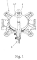
- the miter saw shown in the figures is based on the essential, for the Explanation of the invention necessary components limited. So is the in Fig. 1 illustrated miter saw substantially only from a support 1 and a workpiece support surface 2 forming turntable 3. All others for a miter saw, although functionally necessary, but to explain the invention unnecessary components, such as z. As an attached to an indicated here tilt arrangement 4 bracket with a swiveling saw unit, are intentionally in the figures has been omitted to focus attention on the essential.
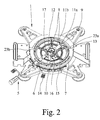
- Fig. 2 shows the miter saw according to the invention without turntable 3, wherein a normally attached to the turntable 3 actuator 5 here continues is shown to illustrate the operation.
- a turntable fixing device 6 is operated, about the turntable 3 with respect to the carrier 1 graded and fixed reproducible can be, for example, by the turntable fixing device 6 in Intervention with the provided in a miter 7 miter scoring device.
- the miter notches are so in the along the circumference of the turntable 3 extending Miter 7 arranged that with the turntable fixing device 6 a few predetermined first angular positions are stepped can.
- Fig. 2 further shows a preferred turntable fixing device 8, with which it is additionally possible, the turntable 3 opposite to fix the carrier 1 in a further second angular position, wherein the particular advantage of the invention is achieved in that the second angular position at the same time stepless and reproducible.
- Stepless means that in Contrary to the first turntable fixing device 6 shown above not only a few angular positions are selectable, but that any other angular positions, completely independent of predetermined stop marks, can be adjusted.
- FIG. 2 The illustrated in Fig. 2 preferred embodiment of an inventive Miter saw shows the turntable fixing device 8, the present from a formed to a latching arm base 9, a locking arm fixing device 10 and a locking means 11 a, b, wherein the latching arm 9 and the Locking arm fixing device 10 rotatably mounted on a cylindrical holder 12 of the Carrier 1 are stored.
- the cylindrical holder 12 encloses at the same time concentric with the axis of rotation of the turntable.
- the latching arm 9 is in any desired angular position with the aid of the latching arm fixing device 10 fixable with respect to the carrier 1, and via the locking means 11a, b, the turntable 3 can be detachably connected to the latching arm 9.
- the turntable 3 is mounted on the carrier 1 is, in particular so that the turntable 3 via a sliding guide 13 on the Carrier 1 rests. Furthermore, it is assumed that in the starting position of the Locking arm 9 is connected to the turntable 3 via the locking means 11 a, b. By loosening the locking arm fixing device 10 of the locking arm 9 is about the cylindrical Holder 12 freely rotatable, and thus follows one steplessly through the User made rotation of the turntable 3 in the desired second Angular position.
- the locking arm 9 in the second continuously adjusted angular position can be securely fixed.
- the turntable 3 in any other position for. B. the first angular position to be offset, the - the second angular position defining - locking arm 9 while it is stationary. If the second angular position the turntable 3 is to be found again, is the turntable 3 only to turn again in the direction of the second angular position, so long until the turntable 3 again with the locking arm 9 via the locking means 11 a, b is fixed.
- the latching arm fixing device 10 is in the illustrated preferred embodiment designed so that the cylindrical holder 12 and the locking arm fixing device 10 via corresponding threads engaged with each other stand and the locking arm 9 by screw action between the locking arm fixing device 10 and the carrier 1 clamped and thus fixed can.
- the region of the cylindrical holder 12, that of the locking arm 9 is enclosed and / or the locking arm 9 no thread on, so that the mobility the locking arm 9 in the case of the released locking arm fixing device 10th is ensured.
- Figs. 2 and 4 is a preferred embodiment of the latching arm fixing device 10, wherein the locking arm fixing device 10 is divided into two parts is constructed, namely a locking arm actuator 14 and a locking arm screw 15 includes.
- the two mentioned elements are the same constructed so that they are connected to each other in any rotational position can be.
- the locking means 11a, b is divided into two and to a part 11a associated with the turntable 3 and the other part 11b the latching arm 9.
- Fig. 2 shows Fig. 2 also the part 11 a of the locking means 11 a, b, which associated with the turntable 3 is, although the turntable 3 is not shown.
- the part 11a of the locking means 11a, b firmly associated with the turntable 3, which in Fig. 3 is clearly visible.
- the rotary table 3 associated part 11 a of the locking means 11 a, b exists here from a ball holder 18 with a ball 19.
- the ball holder 18 can also be seen in FIGS. 2 and 3.
- the open and in the assembled state of the Turntable 3 to the other part 11b of the locking means 11a, b facing end the ball holder 18 is designed so that the ball 19 fixed in the ball holder 18 is held and partially out of the open end of the ball holder 18 can stand out.
- the other part 11b of the locking means 11a, b is accordingly as a ball seat 20 formed in the latching arm 9.
- the ball seat 20 is made preferably from a recess provided in the locking arm 9 recess or depression.
- the rotary table 3 associated part 11a of the locking means 11a, b is such arranged that he in the assembled state of the miter saw according to the invention in the, associated with the latching arm 9, corresponding other part 11 b of the Arret istsstoffs 11 a, b, so in the ball seat 20, can engage. This happens by overcoming a certain resistance while turning Pushing over both parts of the locking means 11 a, b, so at Turning the ball holder 18 with the ball 19 in the ball seat 20th
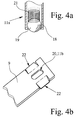
- FIG. 4 a shows a detailed view of the ball holder 18.
- the ball 19 by a spring 21 against the Opening the ball holder 18 is pressed.
- the through the spring bearing of the ball 19 achieved in the ball holder 18 elasticity of the locking means 11 a, b can be further improved by that preferably also the locking arm.
- 9 is formed elastically, in particular so that an elastic deformation of Rastarmes 9 substantially in the axial direction of the cylindrical holder 12th is provided, ie in the direction of the vertical axis around which the turntable. 3 rotates.
- Miter saw is placed on an elastic bearing of the ball 19 in omitted the ball holder 18 and only the locking arm 9 in the above-described Way elastically formed.
- the locking means 11a, b is preferably designed so that a "gentle" Engagement of both parts of the locking means 11a, b is possible.
- a "gentle" Engagement of both parts of the locking means 11a, b is possible.
- This is achieved in that the resulting upon rotation of the turntable 3 first Berzierstellen 22 between the ball 19 and the locking arm 9 ramp-shaped flattened, so that a resistance to the rotational movement continuously can build up to the ball 19 in the ball seat 20 jump locks.
- Stops 23 a, b provided, the movement of the latching arm 9 and thus the Limit maximum positions of possible second angular positions.
- the illustrated Stops 23a, b preferably mark different amounts Angular positions.
- the two different, designated by the stops 23a, b Angular positions are preferably 50 ° and 60 °.
Abstract
Description
Die vorliegende Erfindung betrifft eine Gehrungssäge mit Winkeleinstellung
gemäß dem Oberbegriff des Anspruchs 1.The present invention relates to a miter saw with angular adjustment
according to the preamble of
Gehrungssägen der in Rede stehenden Art sind in verschiedenen Ausführungsformen seit längerem bekannt, meist in Zusammenhang mit der Verwendung von Kreissägen. Gehrungssägen mit Winkeleinstellung werden beispielsweise in der Form von Tischkreissägen (DE 297 21 091 U1) oder auch als kombinierte Kapp-und Gehrungssägen (DE 201 14 319 U1, DE 203 13 885 U1) verwendet. Sie werden zur Bearbeitung aller Arten von Werkstoffen eingesetzt. Ein besonderes Anwendungsfeld finden derartige Gehrungssägen bei der Holzbearbeitung. Das schließt nicht aus, daß die Lehre der vorliegenden Erfindung für Gehrungssägen anderer Einsatzgebiete, insbesondere für die Kunststoffbearbeitung und Metallbearbeitung, Anwendung finden kann.Miter saws of the type in question are in various embodiments Known for some time, mostly in connection with the use of Circular saws. Miter saws with angle adjustment, for example, in the Form of table circular saws (DE 297 21 091 U1) or as a combined Kapp and Miter saws (DE 201 14 319 U1, DE 203 13 885 U1) used. you are used to process all types of materials. A special Field of application find such miter saws in woodworking. The does not exclude that the teaching of the present invention for miter saws other applications, in particular for plastics processing and metalworking, Application can be found.
Gehrungssägen der in Rede stehenden Art umfassen üblicherweise einen feststehenden Träger und einen in oder an dem Träger drehbaren Drehtisch, wobei das zu bearbeitende Werkstück auf dem Drehtisch und häufig auch auf einem als Werkstückauflagefläche ausgebildeten Teil des Trägers zu liegen kommt. Eine am Träger installierte Anschlagschiene sichert meist das Werkstück beim Sägevorgang vor Verrutschen, indem das Werkstück beim Sägevorgang gegen die Anschlagschiene gedrückt wird.Miter saws of the type in question usually comprise a fixed one Carrier and a rotatable in or on the carrier turntable, wherein the to be machined workpiece on the turntable and often on a as Workpiece support surface formed part of the carrier comes to rest. A The support rail installed on the support usually secures the workpiece during the sawing process against slipping by the workpiece during the sawing against the Stop rail is pressed.
Der um eine Hochachse drehbare Drehtisch trägt gleichzeitig eine Halterung für das Sägeaggregat, so daß durch Drehung des Drehtisches auch das Sägeaggregat in gleicher Weise mitbewegt wird. Bei Drehung des Drehtisches aus seiner Mittelstellung heraus schließt die durch das Sägeblatt definierte Schnittebene mit der zu der Mittelstellung korrespondierenden Schnittebene einen Sägewinkel, den Gehrungswinkel, ein. An dem Werkstück kann somit ein Gehrungsschnitt durchgeführt werden.The rotatable about a vertical axis turntable also carries a holder for the saw unit, so that by rotation of the turntable and the saw unit is moved in the same way. When turning the turntable from its center position out closes the section defined by the saw blade with the to the center position corresponding cutting plane a sawing angle, the Miter angle, a. Thus, a miter cut is made on the workpiece become.
Um einen Gehrungsschnitt sicher durchführen zu können, ist es notwendig, den Drehtisch in der gewählten Winkelstellung zu fixieren. Dazu sind verschiedene konstruktive Maßnahmen bekannt. Üblicherweise erlauben Gehrungssägen die stufenhafte und reproduzierbare Fixierung des Drehtisches in vorgegebenen Winkelstellungen, wie z. B. ± 15°, ± 30°, ± 45° und ± 60° von der Mittelstellung. Zur Fixierung dieser Winkelstellungen dient beispielsweise ein parallel zum Umfang des Drehtisches verlaufender Gehrungsbogen mit Gehrungskerben an den vorgegebenen Winkelstellungen. Ein mit dem Drehtisch verbundener elastischer Rastarm ermöglicht die Fixierung des Drehtisches in der gewünschten Winkelstellung, indem er in die Gehrungskerbe einrastet (DE 201 14 319 U1).To make a miter cut safely, it is necessary to To fix turntable in the selected angular position. These are different constructive measures known. Miter saws usually allow the gradual and reproducible fixation of the turntable in given Angular positions, such. B. ± 15 °, ± 30 °, ± 45 ° and ± 60 ° from the center position. To fix these angular positions, for example, serves a parallel to the circumference of the turntable running miter with miter notches to the predetermined angular positions. An elastic connected to the turntable Locking arm allows the fixation of the turntable in the desired angular position, by locking into the miter notch (DE 201 14 319 U1).
Es ist weiterhin eine Gehrungssäge der in Rede stehenden Art bekannt, bei der die Winkeleinstellung zwei verschiedene Möglichkeiten der Feststellung aufweist. Neben der oben beschriebenen Möglichkeit, den Drehteller nur unter bestimmten Winkeln gegenüber dem Träger zu fixieren, ist es dann z. B. möglich, den Drehteller in beliebigen Winkelstellungen zu fixieren, z. B. durch eine zusätzliche Klemmvorrichtung (DE 203 13 885 U1). Die stufenlos festgelegte Winkelstellung ist allerdings nicht reproduzierbar im Sinne einer leicht wiederauffmdbaren Rastposition.It is also known a miter saw of the type in question, in the the angle adjustment has two different ways of detection. In addition to the possibility described above, the turntable only under certain To fix angles with respect to the carrier, it is then z. Possible, to fix the turntable in any angle, z. B. by an additional Clamping device (DE 203 13 885 U1). The infinitely fixed However, angular position is not reproducible in the sense of an easily recoverable Click.
Der Lehre der vorliegenden Erfindung liegt das Problem zugrunde, eine Gehrungssäge so auszugestalten und weiterzubilden, daß eine Winkelstellung stufenlos wählbar und zugleich sicher reproduzierbar einstellbar ist.The teaching of the present invention is based on the problem of a miter saw to design and further develop that an angular position stepless selectable and at the same time reliably reproducible adjustable.
Die zuvor aufgezeigte Problemstellung ist gelöst bei einer Gehrungssäge mit den
Merkmalen des Oberbegriffs 1 von Anspruch 1 durch die Merkmale des kennzeichnenden
Teils von Anspruch 1.The above-indicated problem is solved in a miter saw with the
Features of the
Der Grundgedanke der Lehre liegt zunächst darin, eine aus dem Stand der Technik bekannten Drehtisch-Fixiervorrichtung zur Fixierung des Drehtisches gegenüber dem Träger in einer reproduzierbaren Winkelstellung so auszugestalten, daß die Drehtisch-Fixiervorrichtung die Einstellung mindestens einer Winkelstellung zugleich stufenlos und reproduzierbar ermöglicht.The basic idea of the teaching lies first therein, one from the prior art known turntable fixing device for fixing the turntable opposite the carrier in a reproducible angular position in such a way that the turntable fixing device setting at least one angular position at the same time continuously and reproducibly made possible.
Stufenlos bedeutet hier, daß die Wahl der Winkelstellung nicht auf einige wenige vorherbestimmte Winkel beschränkt ist, wie dies bei aus dem Stand der Technik bekannten Drehtisch-Fixiervorrichtungen üblich ist. Stepless here means that the choice of angular position not on a few predetermined angle is limited, as in the prior art known turntable fixing devices is common.
Die sich von den stufenlosen, aus dem Stand der Technik bekannten Winkeleinstellungen durch die Reproduzierbarkeit unterscheidende erfindungsgemäße Winkeleinstellung ist im Sinne einer leicht auffindbaren zusätzlichen Rastposition zu verstehen, die ein sicheres und effizientes Arbeiten ermöglicht, da aufwendige Justierarbeiten beim Wiederauffinden der stufenlosen Winkelstellung entfallen. Durch diese Maßnahme ist es dem Verwender der erfindungsgemäßen Gehrungssäge z. B. auf vorteilhafte Weise möglich, zwischen Gehrungsschnitten in einer bestimmten ersten Winkelstellung und Gehrungsschnitten unter Verwendung der stufenlos eingestellten und zugleich reproduzierbar erreichbaren zweiten Winkelstellung zu wechseln.The from the stepless, known from the prior art angle settings by the reproducibility of the invention differing Angle adjustment is in the sense of an easily findable additional locking position to understand, which allows a safe and efficient work, as elaborate Adjustments when retrieving the stepless angular position omitted. By this measure, it is the user of the invention Miter saw z. B. possible in an advantageous manner, between miter cuts in a particular first angular position and miter cuts using the infinitely adjustable and at the same time reproducibly achievable to change the second angular position.
Es gibt eine Vielzahl von Möglichkeiten, die Lehre der Erfindung auszugestalten und weiterzubilden. Dazu darf auf die Unteransprüche verwiesen werden. Zu einzelnen Unteransprüchen sind noch besondere Bemerkungen angezeigt.There are a variety of ways to design the teachings of the invention and further education. For this purpose, reference may be made to the dependent claims. To individual subclaims are still special comments displayed.
Anspruch 2 umreißt einen vorteilhaften konstruktiven Aufbau der zweiten Drehtisch-Fixiervorrichtung
zur stufenlosen und zugleich reproduzierbaren Einstellung
einer Fixierung der zweiten Winkelstellung. Danach umfaßt die Drehtisch-Fixiervorrichtung
eine am Träger drehbar gelagerte und in einer stufenlos einstellbaren
Winkelstellung fixierbare Basis, wobei der Drehtisch auch gegenüber
der Basis drehbar ist und in einer bestimmten Drehstellung gegenüber der Basis
mit dieser über ein Arretierungsmittel lösbar verbunden ist. Nach Anspruch 3 ist
es darüber hinaus besonders vorteilhaft, wenn die Basis vom Drehtisch drehend
mitgeführt werden kann, vorausgesetzt, daß die Basis und der Drehtisch über das
Arretierungsmittels miteinander verbunden sind und die Basis nicht am Träger
fixiert ist.
Soll mit der oben beschriebenen Konstruktion eine Winkelstellung stufenlos und reproduzierbar definiert werden, so ist der Drehtisch zunächst so über die Basis zu bewegen, daß sich Basis und Drehtisch über das Arretierungsmittel miteinander verbinden. Durch Lösen der Rastarm-Fixiervorrichtung ist die Basis frei drehbar und sie folgt aufgrund der Wirkung des Arretierungsmittels der weiteren Drehung des Drehtisches in die gewünschte Winkelstellung. Durch Anziehen der Rastarm-Fixiervorrichtung ist die Basis in der nun erreichten Winkelstellung fixierbar. Wenn der Drehtisch nun in seine erste - oder eine andere
- Winkelstellung zurückkehren soll, kann der Drehtisch durch Lösen der über das Arretierungsmittel bewirkten Verbindung von Drehtisch und Basis von der Basis getrennt werden, ohne daß die Basis die zuvor stufenlos und reproduzierbar definierte Winkelstellung verliert. Der nunmehr frei bewegliche Drehtisch läßt sich sodann ohne weiteres in eine andere bzw. die erste Winkelstellung bringen.
- To return angular position, the turntable can be separated from the base by loosening about the Arretierungsmittel caused connection of turntable and base, without the base loses the previously stepless and reproducible defined angular position. The now freely movable turntable can then easily bring in another or the first angular position.
Das Wiederauffinden der stufenlosen und reproduzierbaren Winkelstellung ist schließlich sehr einfach möglich. Hierzu muß lediglich der Drehtisch aus der ersten Winkelstellung freigegeben und in Richtung der durch die fixierte Basis definierten Winkelstellung gedreht werden, bis der Drehtisch durch das Arretierungsmittel an der Basis und damit in der stufenlos reproduzierbaren Winkelstellung fixiert wird.The retrieval of stepless and reproducible angular position is finally very easy. For this purpose, only the turntable from the first Angle position released and in the direction of the defined by the fixed base Angular position can be rotated until the turntable through the locking means at the base and thus in the continuously reproducible angular position is fixed.
Nach den untergeordneten Ansprüchen 9 und 10 läßt sich das Arretierungsmittel
besonders vorteilhaft als ein Kugel-Schnappverschluß ausbilden, wobei das Arretierungsmittel
dann aus einer am Drehtisch befestigten Kugelhalterung mit einer
Kugel und einer der Basis zugeordneten Kugelaufnahme besteht, wobei Kugel
und Kugelaufnahme federnd gegeneinander verspannt sind und die Kugel
demzufolge in der stufenlosen und reproduzierbaren Winkelstellung in die Kugelaufnahme
einschnappt.According to the
Im folgenden wird nun die Erfindung anhand einer lediglich ein Ausführungsbeispiel darstellenden Zeichnung näher erläutert. In der Zeichnung zeigt
- Fig. 1
- ein bevorzugtes Ausführungsbeispiel einer erfindungsgemäßen Gehrungssäge im montierten Zustand,
- Fig. 2
- die Gehrungssäge aus Fig. 1 mit demontiertem Drehtisch,
- Fig. 3
- die unterseitige Ansicht des Drehtisches aus Fig. 1 und
- Fig. 4a, b
- eine Detailansicht der Gehrungssäge aus Fig. 2 zur Verdeutlichung des Arretierungsmittels.
- Fig. 1
- A preferred embodiment of a miter saw according to the invention in the assembled state,
- Fig. 2
- the miter saw of FIG. 1 with a turntable removed,
- Fig. 3
- the underside view of the turntable of Fig. 1 and
- Fig. 4a, b
- a detailed view of the miter saw of Fig. 2 to illustrate the locking means.
Im folgenden wird die erfindungsgemäße Gehrungssäge anhand eines bevorzugten Ausführungsbeispiels einer Kapp- und Gehrungssäge beschrieben. Genausogut könnte die Erfindung auch anhand einer beliebigen anderen Gehrungssäge beschrieben werden, wie z. B. anhand einer Tischkreissäge, die das Ausführen von Gehrungsschnitten erlaubt. Ganz allgemein ist also die einzige Voraussetzung für die Verwirklichung der Lehre lediglich die Funktion der Gehrungssäge. Weiterführende Funktionalitäten, die Gehrungssägen aufweisen können, wie z. B. Kapp-, Schifter- und Zugfunktion können jeweils vorhanden sein, müssen dies aber nicht.In the following, the miter saw according to the invention is based on a preferred Embodiment of a miter saw described. As good as the invention could also be based on any other miter saw be described, such. B. based on a table saw, the running allowed by miter cuts. In general, therefore, the only requirement for the realization of the teaching only the function of the miter saw. Additional functionalities that may include miter saws, such as z. B. Kapp-, Schifter- and traction can each be present must but not.
Die in den Figuren dargestellte Gehrungssäge ist auf die wesentlichen, für die
Erläuterung der Erfindung notwendigen Bestandteile beschränkt. So besteht die
in Fig. 1 dargestellte erfindungsgemäße Gehrungssäge im wesentlichen lediglich
aus einem Träger 1 und einem eine Werkstückauflagefläche 2 bildenden Drehtisch
3. Alle weiteren für eine Kapp- und Gehrungssäge zwar funktionsnotwendigen,
aber zur Erläuterung der Erfindung nicht notwendigen Bestandteile, wie
z. B. eine an einer hier angedeuteten Neigungsanordnung 4 angebrachte Halterung
mit einem schwenkbaren Sägeaggregat, sind in den Figuren absichtlich
weggelassen worden, um den Blick auf das wesentliche zu lenken.The miter saw shown in the figures is based on the essential, for the
Explanation of the invention necessary components limited. So is the
in Fig. 1 illustrated miter saw substantially only
from a
Fig. 2 zeigt die erfindungsgemäße Gehrungssäge ohne Drehtisch 3, wobei ein
normalerweise an dem Drehtisch 3 befestigtes Betätigungselement 5 hier weiterhin
dargestellt ist, um die Funktionsweise veranschaulichen zu können.Fig. 2 shows the miter saw according to the invention without
Über das Betätigungselement 5 ist eine Drehtisch-Fixiervorrichtung 6 bedienbar,
über die der Drehtisch 3 gegenüber dem Träger 1 gestuft und reproduzierbar fixiert
werden kann, indem die Drehtisch-Fixiervorrichtung 6 beispielsweise in
Eingriff mit den in einem Gehrungsbogen 7 vorgesehenen Gehrungskerben gerät.
Die Gehrungskerben sind so in dem entlang des Umfangs des Drehtisches 3 verlaufenden
Gehrungsbogen 7 angeordnet, daß mit der Drehtisch-Fixiervorrichtung
6 einige wenige vorgegebene erste Winkelstellungen gestuft eingestellt werden
können.Via the
Wie genau die Fixierung der ersten Winkelstellung mit Hilfe der gestuften Drehtisch-Fixiervorrichtung
6 konstruktiv gelöst ist, ob dies durch Eingriff der Drehtisch-Fixiervorrichtung
6 mit den Gehrungskerben des Gehrungsbogens 7 geschieht,
oder in anderer, dem Fachmann geläufigen Weise, ist für den Gegenstand
der vorliegenden Erfindung unerheblich; es bleibt dem Fachmann überlassen,
die Drehtisch-Fixiervorrichtung 6 zur Einstellung bestimmter, reproduzierbarer
Winkelstellungen in geeigneter Weise umzusetzen; hierzu wird nochmals
auf den weiter oben genannten Stand der Technik verwiesen.How exactly the fixation of the first angular position by means of the stepped
Das Ausführungsbeispiel in Fig. 2 zeigt weiterhin eine bevorzugte Drehtisch-Fixiervorrichtung
8, mit der es zusätzlich möglich ist, den Drehtisch 3 gegenüber
dem Träger 1 in einer weiteren zweiten Winkelstellung zu fixieren, wobei der
besondere, erfindungsgemäße Vorteil dadurch erzielt wird, daß die zweite Winkelstellung
zugleich stufenlos und reproduzierbar ist. Stufenlos bedeutet, daß im
Gegensatz zur ersten, oben dargestellten Drehtisch-Fixiervorrichtung 6 nicht nur
einige wenige Winkelstellungen auswählbar sind, sondern daß auch beliebige
andere Winkelstellungen, vollkommen unabhängig von vorgegebenen Rastmarken,
eingestellt werden können.The embodiment in Fig. 2 further shows a preferred
Unter der Reproduzierbarkeit einer Winkelstellung wird im Rahmen der vorliegenden
Erfindung nicht alleine die grundsätzliche Möglichkeit des Wiederauffindens
einer einmal gewählten Winkelstellung verstanden, wie z. B. das durch
Drehung des Drehtisches 3 durch den Benutzer vorzunehmende Aufeinanderausrichten
zweier optischer Marken (z. B. Nonius). Vielmehr wird darunter verstanden,
daß die Reproduktion einer Winkelstellung durch eine mechanische, konstruktive
Maßnahme, wie z. B. eine leicht auffindbare zusätzliche Rastposition,
sichergestellt wird.Under the reproducibility of an angular position is within the present
Invention not alone the fundamental possibility of retrieval
understood a once selected angular position, such. B. by
Rotation of the
Das in Fig. 2 dargestellte bevorzugte Ausführungsbeispiel einer erfindungsgemäßen
Gehrungssäge zeigt die Drehtisch-Fixiervorrichtung 8, die vorliegend aus
einer zu einem Rastarm ausgebildeten Basis 9, einer Rastarm-Fixiervorrichtung
10 und einem Arretierungsmittel 11a, b besteht, wobei der Rastarm 9 und die
Rastarm-Fixiervorrichtung 10 drehbar auf einer zylindrischen Halterung 12 des
Trägers 1 gelagert sind. Die zylindrische Halterung 12 umschließt dabei gleichzeitig
konzentrisch die Drehachse des Drehtisches 3.The illustrated in Fig. 2 preferred embodiment of an inventive
Miter saw shows the
Der Rastarm 9 ist mit Hilfe der Rastarm-Fixiervorrichtung 10 in beliebiger Winkelstellung
bezüglich dem Träger 1 fixierbar, und über das Arretierungsmittel
11a, b läßt sich der Drehtisch 3 lösbar mit dem Rastarm 9 verbinden. The latching
Mit Hilfe des gegenüber dem Träger 1 stufenlos feststellbaren und mit dem
Drehtisch 3 verbindbaren Rastarms 9 ist nun eine stufenlos einstellbare Winkelstellung
des Drehtisches 3 beliebig oft reproduzierbar möglich, was im folgenden
ausführlich beschrieben wird.With the help of the relative to the
Hierzu sei zunächst angenommen, daß der Drehtisch 3 auf dem Träger 1 montiert
ist, insbesondere so, daß der Drehtisch 3 über eine Gleitführung 13 auf dem
Träger 1 aufliegt. Weiterhin sei angenommen, daß in der Ausgangsstellung der
Rastarm 9 mit dem Drehtisch 3 über das Arretierungsmittel 11a, b verbunden ist.
Durch Lösen der Rastarm-Fixiervorrichtung 10 ist der Rastarm 9 um die zylindrische
Halterung 12 frei drehbar, und er folgt somit stufenlos einer durch den
Benutzer vorgenommenen Drehung des Drehtisches 3 in die gewünschte zweite
Winkelstellung.For this purpose, it is first assumed that the
Durch Anziehen der Rastarm-Fixiervorrichtung 10 kann der Rastarm 9 in der
zweiten stufenlos eingestellten Winkelstellung sicher fixiert werden. Durch Lösen
der durch das Arretierungsmittel 11a, b verursachten Verbindung von Drehtisch
3 und Rastarm 9 kann der Drehtisch 3 in eine beliebige andere Position, z.
B. die erste Winkelstellung, versetzt werden, wobei der ― die zweite Winkelstellung
definierende ― Rastarm 9 währenddessen ortsfest ist. Wenn die zweite Winkelstellung
des Drehtisches 3 wieder aufgefunden werden soll, ist der Drehtisch
3 lediglich wieder in Richtung der zweiten Winkelstellung zu drehen, so lange,
bis der Drehtisch 3 wieder mit dem Rastarm 9 über das Arretierungsmittel 11a, b
fixiert ist.By tightening the locking
Die Rastarm-Fixiervorrichtung 10 ist in dem dargestellten bevorzugten Ausführungsbeispiel
so ausgeführt, daß die zylindrische Halterung 12 und die Rastarm-Fixiervorrichtung
10 über korrespondierende Gewindegänge miteinander in Eingriff
stehen und der Rastarm 9 durch Schraubwirkung zwischen der Rastarm-Fixiervorrichtung
10 und dem Träger 1 eingespannt und somit fixiert werden
kann. Dabei weist der Bereich der zylindrischen Halterung 12, der vom Rastarm
9 umschlossen wird und/oder der Rastarm 9 kein Gewinde auf, damit die Beweglichkeit
des Rastarms 9 im Falle der gelösten Rastarm-Fixiervorrichtung 10
sichergestellt ist. The latching
In den Fig. 2 und 4 ist eine bevorzugte Ausführungsform der Rastarm-Fixiervorrichtung
10 dargestellt, wobei die Rastarm-Fixiervorrichtung 10 zweigeteilt
aufgebaut ist, nämlich ein Rastarm-Betätigungselement 14 und ein Rastarm-Schraubelement
15 umfaßt. Dabei sind die beiden genannten Elemente so
konstruiert, daß sie miteinander in beliebiger Drehstellung zueinander verbunden
werden können.In Figs. 2 and 4 is a preferred embodiment of the latching
Dies bringt den fertigungstechnischen Vorteil mit sich, daß das von dem Bediener
zu bedienende Rastarm-Betätigungselement 14 immer in gleicher Art und
Weise in Bezug auf den Träger 1 montierbar ist. Damit ist gemeint, daß die
durch Drehen des Rastarm-Betätigungselements 14 vorzunehmende Lösung und
Festsetzung des Rastarms 9 immer in den gleichen Stellungen relativ zum Träger
1 vornehmbar ist. Diese Eigenschaft wird in dem dargestellten bevorzugten Ausführungsbeispiel
dadurch erzielt, daß das Rastarm-Schraubelement 15 mit dem
Rastarm-Betätigungselement 14 über eine justierbare Langloch-Zapfenverbindung
16, 17 verbunden ist.This brings the manufacturing advantage that that of the operator
to be used locking
Es sind verschiedene Möglichkeiten denkbar, das Arretierungsmittel 11a, b auszubilden.
In der in Fig. 2 und in einer Detailansicht in Fig. 4a, b dargestellten bevorzugten
Ausführungsform ist das Arretierungsmittel 11a, b zweigeteilt und zu
einem Teil 11a dem Drehtisch 3 und zum anderen Teil 11b dem Rastarm 9 zugeordnet.There are various possibilities conceivable to form the locking means 11a, b.
In the in Fig. 2 and in a detailed view in Fig. 4a, b shown preferred
Embodiment, the locking means 11a, b is divided into two and to
a
Um die Funktionsweise des Arretierungsmittels 11 a, b zu verdeutlichen, zeigt
Fig. 2 auch den Teil 11a des Arretierungsmittels 11a, b, der dem Drehtisch 3 zugeordnet
ist, obwohl der Drehtisch 3 nicht dargestellt ist. Tatsächlich ist der Teil
11 a des Arretierungsmittels 11a, b fest dem Drehtisch 3 zugeordnet, was in Fig.
3 deutlich zu sehen ist. Wie bereits weiter oben beschrieben worden ist, gelangen
die beiden Teile des Arretierungsmittels 11a, b durch Drehen des Drehtisches 3
in Eingriff, so daß als Konsequenz auch der Drehtisch 3 mit dem Rastarm 9 verbunden
werden kann.To illustrate the operation of the locking means 11 a, b, shows
Fig. 2 also the
Eine bevorzugte Ausführungsform des Arretierungsmittels 11a, b zeigt Fig. 4a,
b. Der dem Drehtisch 3 zugeordnete Teil 11 a des Arretierungsmittels 11a, b besteht
hier aus einer Kugelhalterung 18 mit einer Kugel 19. Die Kugelhalterung
18 ist auch in Fig. 2 und 3 zu erkennen. Das offene und im Montagezustand des
Drehtisches 3 zum anderen Teil 11b des Arretierungsmittels 11a, b weisende Ende
der Kugelhalterung 18 ist so ausgestaltet, daß die Kugel 19 fest in der Kugelhalterung
18 gehalten wird und teilweise aus dem offenen Ende der Kugelhalterung
18 herausragen kann.A preferred embodiment of the locking means 11a, b, Fig. 4a,
b. The rotary table 3 associated
Der andere Teil 11b des Arretierungsmittels 11a, b ist entsprechend als eine Kugelaufnahme
20 in dem Rastarm 9 ausgebildet. Die Kugelaufnahme 20 besteht
vorzugsweise aus einer im Rastarm 9 vorgesehenen Aussparung oder Vertiefung.
Der dem Drehtisch 3 zugeordnete Teil 11a des Arretierungsmittels 11a, b ist derart
angeordnet, daß er im Montagezustand der erfindungsgemäßen Gehrungssäge
in den, dem Rastarm 9 zugeordneten, korrespondierenden anderen Teil 11b des
Arretierungsmittels 11a, b, also in die Kugelaufnahme 20, einrasten kann. Dies
geschieht unter Überwindung eines gewissen Widerstandes beim drehenden
Übereinanderschieben beider Teile des Arretierungsmittels 11a, b, also beim
Drehen der Kugelhalterung 18 mit der Kugel 19 in die Kugelaufnahme 20.The
Fig. 4a zeigt eine Detailansicht der Kugelhalterung 18. In dem dargestellten bevorzugten
Ausführungsbeispiel wird die Kugel 19 durch eine Feder 21 gegen die
Öffnung der Kugelhalterung 18 gedrückt. Die durch die Federlagerung der Kugel
19 in der Kugelhalterung 18 erzielte Elastizität des Arretierungsmittels 11a, b
läßt sich zusätzlich dadurch verbessern, daß vorzugsweise auch der Rastarm 9
elastisch ausgebildet ist, insbesondere so, daß eine elastische Verformung des
Rastarmes 9 im wesentlichen in axialer Richtung der zylindrischen Halterung 12
vorgesehen ist, also in Richtung der Hochachse, um die sich der Drehtisch 3
dreht. In einem weiteren, hier nicht dargestellten Ausführungsbeispiel der erfindungsgemäßen
Gehrungssäge wird auf eine elastische Lagerung der Kugel 19 in
der Kugelhalterung 18 verzichtet und nur der Rastarm 9 in der oben beschriebenen
Weise elastisch ausgebildet.FIG. 4 a shows a detailed view of the
Das Arretierungsmittel 11a, b ist vorzugsweise so ausgebildet, daß ein "sanftes"
Einrasten beider Teile des Arretierungsmittels 11a, b möglich ist. Im Falle der in
den Fig. 2 und 4 dargestellten Ausgestaltung des Arretierungsmittels 11a, b wird
dies dadurch erreicht, daß die sich bei Drehung des Drehtisches 3 ergebenden ersten
Berührstellen 22 zwischen der Kugel 19 und dem Rastarm 9 rampenförmig
abgeflacht sind, so daß sich ein Widerstand gegen die Drehbewegung kontinuierlich
aufbauen kann, bis die Kugel 19 in die Kugelaufnahme 20 sprungartig
einrastet.The locking means 11a, b is preferably designed so that a "gentle"
Engagement of both parts of the locking means 11a, b is possible. In the case of in
Figs. 2 and 4 shown embodiment of the locking means 11a, b is
This is achieved in that the resulting upon rotation of the
In dem in Fig. 2 dargestellten bevorzugten Ausführungsbeispiel sind am Träger 1
Anschläge 23a, b vorgesehen, die die Bewegung des Rastarms 9 und damit die
Maximalpositionen möglicher zweiter Winkelstellungen begrenzen. Die dargestellten
Anschläge 23a, b markieren vorzugsweise betragsmäßig unterschiedliche
Winkelstellungen. Die beiden unterschiedlichen, durch die Anschläge 23a, b bezeichneten
Winkelstellungen liegen vorzugsweise bei 50° und 60°.In the preferred embodiment shown in Fig. 2 are on the carrier. 1
Claims (13)
einem Träger (1),
einem am oder im Träger (1) drehbar angeordneten, eine Werkstückauflagefläche (2) bildenden Drehtisch (3) und
einer Drehtisch-Fixiervorrichtung (8) zur Fixierung des Drehtisches (3) gegenüber dem Träger (1) in bestimmten, reproduzierbaren Winkelstellungen,
dadurch gekennzeichnet, daß die Drehtisch-Fixiervorrichtung (8) die Einstellung mindestens einer Winkelstellung zugleich stufenlos und reproduzierbar ermöglicht.Miter saw with angle adjustment with
a carrier (1),
one on or in the carrier (1) rotatably arranged, a workpiece support surface (2) forming the turntable (3) and
a turntable fixing device (8) for fixing the turntable (3) relative to the carrier (1) in certain, reproducible angular positions,
characterized in that the turntable fixing device (8) allows the setting of at least one angular position at the same time continuously and reproducibly.
Priority Applications (6)
| Application Number | Priority Date | Filing Date | Title |
|---|---|---|---|
| DE200450001342 DE502004001342D1 (en) | 2004-05-03 | 2004-05-03 | Miter saw with angle adjustment |
| EP20040010504 EP1595630B1 (en) | 2004-05-03 | 2004-05-03 | Mitre saw with angular adjustment |
| ES04010504T ES2270215T3 (en) | 2004-05-03 | 2004-05-03 | SAW TO CUT ENGLISH WITH ANGLE ADJUSTMENT. |
| AT04010504T ATE337880T1 (en) | 2004-05-03 | 2004-05-03 | MITER SAW WITH ANGLE ADJUSTMENT |
| US11/110,723 US7302879B2 (en) | 2004-05-03 | 2005-04-21 | Miter saw with angle adjustment |
| CA 2505960 CA2505960C (en) | 2004-05-03 | 2005-05-02 | Miter saw with angle adjustment |
Applications Claiming Priority (1)
| Application Number | Priority Date | Filing Date | Title |
|---|---|---|---|
| EP20040010504 EP1595630B1 (en) | 2004-05-03 | 2004-05-03 | Mitre saw with angular adjustment |
Publications (2)
| Publication Number | Publication Date |
|---|---|
| EP1595630A1 true EP1595630A1 (en) | 2005-11-16 |
| EP1595630B1 EP1595630B1 (en) | 2006-08-30 |
Family
ID=34924840
Family Applications (1)
| Application Number | Title | Priority Date | Filing Date |
|---|---|---|---|
| EP20040010504 Not-in-force EP1595630B1 (en) | 2004-05-03 | 2004-05-03 | Mitre saw with angular adjustment |
Country Status (6)
| Country | Link |
|---|---|
| US (1) | US7302879B2 (en) |
| EP (1) | EP1595630B1 (en) |
| AT (1) | ATE337880T1 (en) |
| CA (1) | CA2505960C (en) |
| DE (1) | DE502004001342D1 (en) |
| ES (1) | ES2270215T3 (en) |
Cited By (1)
| Publication number | Priority date | Publication date | Assignee | Title |
|---|---|---|---|---|
| EP1886752A1 (en) * | 2006-08-11 | 2008-02-13 | Metabowerke GmbH | Chop and mitre saw with a turntable |
Families Citing this family (4)
| Publication number | Priority date | Publication date | Assignee | Title |
|---|---|---|---|---|
| US8061251B2 (en) * | 2004-04-15 | 2011-11-22 | Milwaukee Electric Tool Corporation | Miter adjustment assembly for a saw |
| WO2005102626A2 (en) * | 2004-04-15 | 2005-11-03 | Milwaukee Electric Tool Corporation | Saw, such as a miter saw |
| US8002253B2 (en) * | 2008-06-20 | 2011-08-23 | Robert Bosch Gmbh | Button actuated detent system |
| US9833849B2 (en) | 2016-01-18 | 2017-12-05 | Tti (Macao Commercial Offshore) Limited | Miter saw |
Citations (6)
| Publication number | Priority date | Publication date | Assignee | Title |
|---|---|---|---|---|
| US3487863A (en) * | 1967-03-09 | 1970-01-06 | Thomas Robinson & Son Ltd | Indexing of rotary members of machines |
| US5207141A (en) * | 1991-01-30 | 1993-05-04 | Ryobi Limited | Turntable positioning device of desk type cutting machine |
| EP0779122A2 (en) * | 1995-12-12 | 1997-06-18 | Black & Decker Inc. | Rotatable worktable |
| JPH11226905A (en) * | 1998-02-19 | 1999-08-24 | Hitachi Koki Co Ltd | Angle indexing unit for bench cutter |
| US20030200852A1 (en) * | 2002-04-30 | 2003-10-30 | Ezequiel Romo | Miter cut fine adjustment mechanism |
| US20040079214A1 (en) * | 2001-02-08 | 2004-04-29 | Meredith Daryl S. | Miter saw |
Family Cites Families (8)
| Publication number | Priority date | Publication date | Assignee | Title |
|---|---|---|---|---|
| US5249496A (en) * | 1992-08-13 | 1993-10-05 | Milwaukee Electric Tool Corporation | Indexing detent override mechanism |
| GB2304075B (en) * | 1995-08-10 | 1999-10-20 | Milwaukee Electric Tool Corp | Indexing override mechanism for a slide compound miter saw |
| US5937720A (en) * | 1995-08-10 | 1999-08-17 | Milwaukee Electric Tool Corporation | Lower blade guard actuating mechanism for a slide compound miter saw |
| US5819624A (en) * | 1996-07-30 | 1998-10-13 | Milwaukee Electric Tool Corporation | Indexing override mechanism for a slide compound miter saw |
| AU8336198A (en) * | 1997-06-09 | 1998-12-30 | Elektra Beckum Ag | Transportable bench circular saw |
| US6513412B2 (en) * | 2001-01-09 | 2003-02-04 | Porter Cable Corp. | Adjustment mechanism |
| US6810780B2 (en) * | 2001-05-10 | 2004-11-02 | Black & Decker Inc. | Miter detent override for a sliding compound miter saw |
| TW569908U (en) * | 2002-09-26 | 2004-01-01 | P & F Brother Ind Corp | Apparatus for adjusting and aligning slant cutting angle of cutting machine |
-
2004
- 2004-05-03 ES ES04010504T patent/ES2270215T3/en active Active
- 2004-05-03 AT AT04010504T patent/ATE337880T1/en active
- 2004-05-03 DE DE200450001342 patent/DE502004001342D1/en active Active
- 2004-05-03 EP EP20040010504 patent/EP1595630B1/en not_active Not-in-force
-
2005
- 2005-04-21 US US11/110,723 patent/US7302879B2/en not_active Expired - Fee Related
- 2005-05-02 CA CA 2505960 patent/CA2505960C/en not_active Expired - Fee Related
Patent Citations (6)
| Publication number | Priority date | Publication date | Assignee | Title |
|---|---|---|---|---|
| US3487863A (en) * | 1967-03-09 | 1970-01-06 | Thomas Robinson & Son Ltd | Indexing of rotary members of machines |
| US5207141A (en) * | 1991-01-30 | 1993-05-04 | Ryobi Limited | Turntable positioning device of desk type cutting machine |
| EP0779122A2 (en) * | 1995-12-12 | 1997-06-18 | Black & Decker Inc. | Rotatable worktable |
| JPH11226905A (en) * | 1998-02-19 | 1999-08-24 | Hitachi Koki Co Ltd | Angle indexing unit for bench cutter |
| US20040079214A1 (en) * | 2001-02-08 | 2004-04-29 | Meredith Daryl S. | Miter saw |
| US20030200852A1 (en) * | 2002-04-30 | 2003-10-30 | Ezequiel Romo | Miter cut fine adjustment mechanism |
Non-Patent Citations (1)
| Title |
|---|
| PATENT ABSTRACTS OF JAPAN vol. 1999, no. 13 30 November 1999 (1999-11-30) * |
Cited By (1)
| Publication number | Priority date | Publication date | Assignee | Title |
|---|---|---|---|---|
| EP1886752A1 (en) * | 2006-08-11 | 2008-02-13 | Metabowerke GmbH | Chop and mitre saw with a turntable |
Also Published As
| Publication number | Publication date |
|---|---|
| US7302879B2 (en) | 2007-12-04 |
| US20050241452A1 (en) | 2005-11-03 |
| CA2505960C (en) | 2008-08-19 |
| CA2505960A1 (en) | 2005-11-03 |
| EP1595630B1 (en) | 2006-08-30 |
| ATE337880T1 (en) | 2006-09-15 |
| DE502004001342D1 (en) | 2006-10-12 |
| ES2270215T3 (en) | 2007-04-01 |
Similar Documents
| Publication | Publication Date | Title |
|---|---|---|
| DE4322672B4 (en) | Motor-driven saws | |
| DE3943594C2 (en) | ||
| DE4008224C2 (en) | ||
| DE60202900T2 (en) | Crosscut and miter saw comprising a table with a Einrastsystem and a locking system | |
| EP0144490A2 (en) | Drill or miller guiding device for exchangeable driving machines | |
| DE19523348A1 (en) | Adjustment mechanism of the inclination angle of a compound miter saw | |
| WO1990002633A2 (en) | Clamping device | |
| EP0598248A1 (en) | Hand-operated circular saw with electric motor drive | |
| DE102005052720A1 (en) | Table for a tool | |
| EP2183072A1 (en) | Handheld power tool | |
| EP0223981A1 (en) | Work piece holding device | |
| DE4236425C2 (en) | Miter saw | |
| EP0716898A1 (en) | Saber saw with angularly adjustable guide plate | |
| EP1595630A1 (en) | Mitre saw with angular adjustment | |
| DE19937827A1 (en) | Tool with adjustable stop | |
| DE102012223910A1 (en) | Hand-held power tool e.g. router has height adjustment device with adjusting shaft that is provided to set working height of power tool by displacement of power tool in hollow cylindrical carrier element along longitudinal axis | |
| EP2363233B1 (en) | Tool device | |
| DE3813852C2 (en) | ||
| EP2974839B1 (en) | Manual cutting machine with two mitre bearings | |
| DE3714390C1 (en) | Holding device for the cutting knife of a microtome | |
| EP0118077B1 (en) | Mitring stop | |
| DE112009005456B4 (en) | POWER TOOL WITH DEPTH ADJUSTER | |
| EP3768477A1 (en) | Milling adapter for a workbench | |
| DE10229671A1 (en) | Holder for motorised saw, especially chainsaw, allows saw to be pivoted about axis located in cutting plane defined by flat extension of sword part of saw | |
| DE102009025110A1 (en) | Tilting device with adjustable tilt angle |
Legal Events
| Date | Code | Title | Description |
|---|---|---|---|
| PUAI | Public reference made under article 153(3) epc to a published international application that has entered the european phase |
Free format text: ORIGINAL CODE: 0009012 |
|
| 17P | Request for examination filed |
Effective date: 20050517 |
|
| AK | Designated contracting states |
Kind code of ref document: A1 Designated state(s): AT BE BG CH CY CZ DE DK EE ES FI FR GB GR HU IE IT LI LU MC NL PL PT RO SE SI SK TR |
|
| AX | Request for extension of the european patent |
Extension state: AL HR LT LV MK |
|
| GRAP | Despatch of communication of intention to grant a patent |
Free format text: ORIGINAL CODE: EPIDOSNIGR1 |
|
| GRAS | Grant fee paid |
Free format text: ORIGINAL CODE: EPIDOSNIGR3 |
|
| AKX | Designation fees paid |
Designated state(s): AT BE BG CH CY CZ DE DK EE ES FI FR GB GR HU IE IT LI LU MC NL PL PT RO SE SI SK TR |
|
| GRAA | (expected) grant |
Free format text: ORIGINAL CODE: 0009210 |
|
| AK | Designated contracting states |
Kind code of ref document: B1 Designated state(s): AT BE BG CH CY CZ DE DK EE ES FI FR GB GR HU IE IT LI LU MC NL PL PT RO SE SI SK TR |
|
| PG25 | Lapsed in a contracting state [announced via postgrant information from national office to epo] |
Ref country code: CZ Free format text: LAPSE BECAUSE OF FAILURE TO SUBMIT A TRANSLATION OF THE DESCRIPTION OR TO PAY THE FEE WITHIN THE PRESCRIBED TIME-LIMIT Effective date: 20060830 Ref country code: SK Free format text: LAPSE BECAUSE OF FAILURE TO SUBMIT A TRANSLATION OF THE DESCRIPTION OR TO PAY THE FEE WITHIN THE PRESCRIBED TIME-LIMIT Effective date: 20060830 Ref country code: SI Free format text: LAPSE BECAUSE OF FAILURE TO SUBMIT A TRANSLATION OF THE DESCRIPTION OR TO PAY THE FEE WITHIN THE PRESCRIBED TIME-LIMIT Effective date: 20060830 Ref country code: IT Free format text: LAPSE BECAUSE OF FAILURE TO SUBMIT A TRANSLATION OF THE DESCRIPTION OR TO PAY THE FEE WITHIN THE PRESCRIBED TIME-LIMIT;WARNING: LAPSES OF ITALIAN PATENTS WITH EFFECTIVE DATE BEFORE 2007 MAY HAVE OCCURRED AT ANY TIME BEFORE 2007. THE CORRECT EFFECTIVE DATE MAY BE DIFFERENT FROM THE ONE RECORDED. Effective date: 20060830 Ref country code: NL Free format text: LAPSE BECAUSE OF FAILURE TO SUBMIT A TRANSLATION OF THE DESCRIPTION OR TO PAY THE FEE WITHIN THE PRESCRIBED TIME-LIMIT Effective date: 20060830 Ref country code: FI Free format text: LAPSE BECAUSE OF FAILURE TO SUBMIT A TRANSLATION OF THE DESCRIPTION OR TO PAY THE FEE WITHIN THE PRESCRIBED TIME-LIMIT Effective date: 20060830 Ref country code: IE Free format text: LAPSE BECAUSE OF FAILURE TO SUBMIT A TRANSLATION OF THE DESCRIPTION OR TO PAY THE FEE WITHIN THE PRESCRIBED TIME-LIMIT Effective date: 20060830 Ref country code: PL Free format text: LAPSE BECAUSE OF FAILURE TO SUBMIT A TRANSLATION OF THE DESCRIPTION OR TO PAY THE FEE WITHIN THE PRESCRIBED TIME-LIMIT Effective date: 20060830 Ref country code: RO Free format text: LAPSE BECAUSE OF FAILURE TO SUBMIT A TRANSLATION OF THE DESCRIPTION OR TO PAY THE FEE WITHIN THE PRESCRIBED TIME-LIMIT Effective date: 20060830 |
|
| REG | Reference to a national code |
Ref country code: GB Ref legal event code: FG4D Free format text: NOT ENGLISH |
|
| REG | Reference to a national code |
Ref country code: CH Ref legal event code: EP Ref country code: CH Ref legal event code: NV Representative=s name: KELLER & PARTNER PATENTANWAELTE AG |
|
| REG | Reference to a national code |
Ref country code: IE Ref legal event code: FG4D Free format text: LANGUAGE OF EP DOCUMENT: GERMAN |
|
| REF | Corresponds to: |
Ref document number: 502004001342 Country of ref document: DE Date of ref document: 20061012 Kind code of ref document: P |
|
| GBT | Gb: translation of ep patent filed (gb section 77(6)(a)/1977) |
Effective date: 20061102 |
|
| PG25 | Lapsed in a contracting state [announced via postgrant information from national office to epo] |
Ref country code: SE Free format text: LAPSE BECAUSE OF FAILURE TO SUBMIT A TRANSLATION OF THE DESCRIPTION OR TO PAY THE FEE WITHIN THE PRESCRIBED TIME-LIMIT Effective date: 20061130 Ref country code: DK Free format text: LAPSE BECAUSE OF FAILURE TO SUBMIT A TRANSLATION OF THE DESCRIPTION OR TO PAY THE FEE WITHIN THE PRESCRIBED TIME-LIMIT Effective date: 20061130 Ref country code: BG Free format text: LAPSE BECAUSE OF FAILURE TO SUBMIT A TRANSLATION OF THE DESCRIPTION OR TO PAY THE FEE WITHIN THE PRESCRIBED TIME-LIMIT Effective date: 20061130 |
|
| PG25 | Lapsed in a contracting state [announced via postgrant information from national office to epo] |
Ref country code: PT Free format text: LAPSE BECAUSE OF FAILURE TO SUBMIT A TRANSLATION OF THE DESCRIPTION OR TO PAY THE FEE WITHIN THE PRESCRIBED TIME-LIMIT Effective date: 20070206 |
|
| NLV1 | Nl: lapsed or annulled due to failure to fulfill the requirements of art. 29p and 29m of the patents act | ||
| REG | Reference to a national code |
Ref country code: ES Ref legal event code: FG2A Ref document number: 2270215 Country of ref document: ES Kind code of ref document: T3 |
|
| ET | Fr: translation filed | ||
| REG | Reference to a national code |
Ref country code: IE Ref legal event code: FD4D |
|
| PLBE | No opposition filed within time limit |
Free format text: ORIGINAL CODE: 0009261 |
|
| STAA | Information on the status of an ep patent application or granted ep patent |
Free format text: STATUS: NO OPPOSITION FILED WITHIN TIME LIMIT |
|
| 26N | No opposition filed |
Effective date: 20070531 |
|
| BERE | Be: lapsed |
Owner name: METABOWERKE G.M.B.H. Effective date: 20070531 |
|
| PG25 | Lapsed in a contracting state [announced via postgrant information from national office to epo] |
Ref country code: MC Free format text: LAPSE BECAUSE OF NON-PAYMENT OF DUE FEES Effective date: 20070531 |
|
| PG25 | Lapsed in a contracting state [announced via postgrant information from national office to epo] |
Ref country code: BE Free format text: LAPSE BECAUSE OF NON-PAYMENT OF DUE FEES Effective date: 20070531 |
|
| PG25 | Lapsed in a contracting state [announced via postgrant information from national office to epo] |
Ref country code: GR Free format text: LAPSE BECAUSE OF FAILURE TO SUBMIT A TRANSLATION OF THE DESCRIPTION OR TO PAY THE FEE WITHIN THE PRESCRIBED TIME-LIMIT Effective date: 20061201 |
|
| PG25 | Lapsed in a contracting state [announced via postgrant information from national office to epo] |
Ref country code: EE Free format text: LAPSE BECAUSE OF FAILURE TO SUBMIT A TRANSLATION OF THE DESCRIPTION OR TO PAY THE FEE WITHIN THE PRESCRIBED TIME-LIMIT Effective date: 20060830 |
|
| PGRI | Patent reinstated in contracting state [announced from national office to epo] |
Ref country code: IT Effective date: 20080601 |
|
| PG25 | Lapsed in a contracting state [announced via postgrant information from national office to epo] |
Ref country code: CY Free format text: LAPSE BECAUSE OF FAILURE TO SUBMIT A TRANSLATION OF THE DESCRIPTION OR TO PAY THE FEE WITHIN THE PRESCRIBED TIME-LIMIT Effective date: 20060830 Ref country code: LU Free format text: LAPSE BECAUSE OF NON-PAYMENT OF DUE FEES Effective date: 20070503 |
|
| PG25 | Lapsed in a contracting state [announced via postgrant information from national office to epo] |
Ref country code: TR Free format text: LAPSE BECAUSE OF FAILURE TO SUBMIT A TRANSLATION OF THE DESCRIPTION OR TO PAY THE FEE WITHIN THE PRESCRIBED TIME-LIMIT Effective date: 20060830 Ref country code: HU Free format text: LAPSE BECAUSE OF FAILURE TO SUBMIT A TRANSLATION OF THE DESCRIPTION OR TO PAY THE FEE WITHIN THE PRESCRIBED TIME-LIMIT Effective date: 20070301 |
|
| PGFP | Annual fee paid to national office [announced via postgrant information from national office to epo] |
Ref country code: ES Payment date: 20110524 Year of fee payment: 8 Ref country code: CH Payment date: 20110525 Year of fee payment: 8 |
|
| PGFP | Annual fee paid to national office [announced via postgrant information from national office to epo] |
Ref country code: AT Payment date: 20110520 Year of fee payment: 8 |
|
| PGFP | Annual fee paid to national office [announced via postgrant information from national office to epo] |
Ref country code: IT Payment date: 20110527 Year of fee payment: 8 |
|
| REG | Reference to a national code |
Ref country code: CH Ref legal event code: PL |
|
| REG | Reference to a national code |
Ref country code: AT Ref legal event code: MM01 Ref document number: 337880 Country of ref document: AT Kind code of ref document: T Effective date: 20120503 |
|
| PG25 | Lapsed in a contracting state [announced via postgrant information from national office to epo] |
Ref country code: AT Free format text: LAPSE BECAUSE OF NON-PAYMENT OF DUE FEES Effective date: 20120503 Ref country code: LI Free format text: LAPSE BECAUSE OF NON-PAYMENT OF DUE FEES Effective date: 20120531 Ref country code: CH Free format text: LAPSE BECAUSE OF NON-PAYMENT OF DUE FEES Effective date: 20120531 |
|
| PG25 | Lapsed in a contracting state [announced via postgrant information from national office to epo] |
Ref country code: IT Free format text: LAPSE BECAUSE OF FAILURE TO SUBMIT A TRANSLATION OF THE DESCRIPTION OR TO PAY THE FEE WITHIN THE PRESCRIBED TIME-LIMIT Effective date: 20120503 |
|
| REG | Reference to a national code |
Ref country code: ES Ref legal event code: FD2A Effective date: 20130820 |
|
| PG25 | Lapsed in a contracting state [announced via postgrant information from national office to epo] |
Ref country code: ES Free format text: LAPSE BECAUSE OF NON-PAYMENT OF DUE FEES Effective date: 20120504 |
|
| REG | Reference to a national code |
Ref country code: FR Ref legal event code: PLFP Year of fee payment: 13 |
|
| REG | Reference to a national code |
Ref country code: FR Ref legal event code: PLFP Year of fee payment: 14 |
|
| REG | Reference to a national code |
Ref country code: FR Ref legal event code: PLFP Year of fee payment: 15 |
|
| PGFP | Annual fee paid to national office [announced via postgrant information from national office to epo] |
Ref country code: FR Payment date: 20200519 Year of fee payment: 17 Ref country code: DE Payment date: 20200525 Year of fee payment: 17 |
|
| PGFP | Annual fee paid to national office [announced via postgrant information from national office to epo] |
Ref country code: GB Payment date: 20200522 Year of fee payment: 17 |
|
| REG | Reference to a national code |
Ref country code: DE Ref legal event code: R119 Ref document number: 502004001342 Country of ref document: DE |
|
| GBPC | Gb: european patent ceased through non-payment of renewal fee |
Effective date: 20210503 |
|
| PG25 | Lapsed in a contracting state [announced via postgrant information from national office to epo] |
Ref country code: GB Free format text: LAPSE BECAUSE OF NON-PAYMENT OF DUE FEES Effective date: 20210503 Ref country code: DE Free format text: LAPSE BECAUSE OF NON-PAYMENT OF DUE FEES Effective date: 20211201 |
|
| PG25 | Lapsed in a contracting state [announced via postgrant information from national office to epo] |
Ref country code: FR Free format text: LAPSE BECAUSE OF NON-PAYMENT OF DUE FEES Effective date: 20210531 |