EP1595610A1 - Vorrichtung zur kontinuierlichen Herstellung von längsnahtgeschweissten metallischen Röhrchen - Google Patents
Vorrichtung zur kontinuierlichen Herstellung von längsnahtgeschweissten metallischen Röhrchen Download PDFInfo
- Publication number
- EP1595610A1 EP1595610A1 EP04291191A EP04291191A EP1595610A1 EP 1595610 A1 EP1595610 A1 EP 1595610A1 EP 04291191 A EP04291191 A EP 04291191A EP 04291191 A EP04291191 A EP 04291191A EP 1595610 A1 EP1595610 A1 EP 1595610A1
- Authority
- EP
- European Patent Office
- Prior art keywords
- tube
- ring
- longitudinal slot
- welding
- welded
- Prior art date
- Legal status (The legal status is an assumption and is not a legal conclusion. Google has not performed a legal analysis and makes no representation as to the accuracy of the status listed.)
- Granted
Links
- 229910052751 metal Inorganic materials 0.000 title claims abstract description 25
- 239000002184 metal Substances 0.000 title claims abstract description 25
- 238000010924 continuous production Methods 0.000 title claims 2
- 238000000034 method Methods 0.000 title 1
- 238000003466 welding Methods 0.000 claims abstract description 12
- 229910003460 diamond Inorganic materials 0.000 claims abstract description 10
- 239000010432 diamond Substances 0.000 claims abstract description 10
- 238000004519 manufacturing process Methods 0.000 claims description 7
- 239000000463 material Substances 0.000 claims description 4
- 230000001681 protective effect Effects 0.000 claims description 4
- 238000007493 shaping process Methods 0.000 abstract 1
- XLYOFNOQVPJJNP-UHFFFAOYSA-N water Substances O XLYOFNOQVPJJNP-UHFFFAOYSA-N 0.000 abstract 1
- 238000001816 cooling Methods 0.000 description 3
- 238000000465 moulding Methods 0.000 description 3
- 239000007787 solid Substances 0.000 description 3
- 230000000694 effects Effects 0.000 description 2
- 230000003287 optical effect Effects 0.000 description 2
- 239000013307 optical fiber Substances 0.000 description 2
- 239000010935 stainless steel Substances 0.000 description 2
- 229910001220 stainless steel Inorganic materials 0.000 description 2
- 229910000851 Alloy steel Inorganic materials 0.000 description 1
- 230000001914 calming effect Effects 0.000 description 1
- 239000000498 cooling water Substances 0.000 description 1
- 239000000835 fiber Substances 0.000 description 1
- 239000000314 lubricant Substances 0.000 description 1
- 150000002739 metals Chemical class 0.000 description 1
- 230000006641 stabilisation Effects 0.000 description 1
- 238000011105 stabilization Methods 0.000 description 1
- 238000009966 trimming Methods 0.000 description 1
Images
Classifications
-
- B—PERFORMING OPERATIONS; TRANSPORTING
- B21—MECHANICAL METAL-WORKING WITHOUT ESSENTIALLY REMOVING MATERIAL; PUNCHING METAL
- B21C—MANUFACTURE OF METAL SHEETS, WIRE, RODS, TUBES OR PROFILES, OTHERWISE THAN BY ROLLING; AUXILIARY OPERATIONS USED IN CONNECTION WITH METAL-WORKING WITHOUT ESSENTIALLY REMOVING MATERIAL
- B21C37/00—Manufacture of metal sheets, bars, wire, tubes or like semi-manufactured products, not otherwise provided for; Manufacture of tubes of special shape
- B21C37/06—Manufacture of metal sheets, bars, wire, tubes or like semi-manufactured products, not otherwise provided for; Manufacture of tubes of special shape of tubes or metal hoses; Combined procedures for making tubes, e.g. for making multi-wall tubes
- B21C37/08—Making tubes with welded or soldered seams
- B21C37/0818—Manufacture of tubes by drawing of strip material through dies
Definitions
- the invention relates to a device for producing longitudinally welded Metallic tube according to the preamble of claim 1.
- EP 0 703 017 B1 discloses an apparatus for producing a longitudinally welded joint Metal tube with an outer diameter of 1 to 6 mm known.
- This is a Striped metal strip in a continuous operation of a supply spool, through a mold consisting of several sets of roll tools to a tube with Longitudinal slot shaped, and the longitudinal slot welded.
- the slotted tube is inserted through Tool passed, which holds the band edges of the slot tube together.
- the tool consists of two halves, which on their adjacent surface respectively a groove having a radius of curvature which corresponds to the outer radius of curvature of the slot tube corresponds.
- the tool has a recess, which has a Access to the beam of a laser welding device for welding the longitudinal slot of the tube allows.
- the welded tube passes behind the recess one second area of the tool, which a springback of the band edges in the still Prevent “soft" weld pool and for rapid cooling of the weld should take care of.
- a steel alloy is proposed as a material for the tool.
- EP 0 927 090 B1 discloses an apparatus for producing a metallic tube known, with a molding apparatus, which is an elongated metal strip to the Tube formed, as well as a welding device, the two band edges of the Tube welded together in the welding area.
- a molding apparatus which is an elongated metal strip to the Tube formed, as well as a welding device, the two band edges of the Tube welded together in the welding area.
- the welding area is provided at least one cooled solid, which is the continuous tube contacted outside for cooling.
- the solid In the spot weld, the solid has an opening, which is the passage for a laser beam for welding the longitudinal seam allows.
- the invention is based on the object, the known devices to the effect to improve that large lengths of metallic tubes are produced trouble-free.
- the main advantage of the invention is the fact that by the arrangement of a Ring of wear-resistant material in a water-cooled bracket, the wear is reduced so far that lengths of several kilometers without interruption Manufacturing can be produced. This effect is further enhanced when the shape of the Metal band to the slit tube so that the slotted tube without springback the Band edges a nearly closed tube forms, so that the ring only for Stabilization of the closed tube is used.
- the device according to the invention is advantageously used for the production of Fiber optic cables are used, which are a plurality of optical fibers in one have closed metal tube.
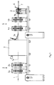
- FIG 1 is a side view of a part of a device for the production of shown thin metal tube.
- a withdrawn from a tape supply no longer shown metal strip 1 is a first forming roller group 2 fed.
- the metal strip 1 is a Stainless steel strip, which for example by means of a likewise not shown Trimming device was cut to a width of 3.1 to 21.5 mm. Before the first forming roller group 2, the metal strip 1 easily with a lubricant be wetted to reduce the friction during molding.
- the first forming roll group 2 has two forming roll pairs 2a and 2b.
- the Form roller pair 2a In the form roller pair 2a, only the band edge regions are initially rounded.
- the Form roller pair 2b forms the metal strip 1 to a U-profile.
- the U-shaped metal band 1 a is fed to a device 3, which a Guide tube 3a has, which projects into the U-shaped metal strip 1 a and behind the weld point opens.
- a Guide tube 3a With the help of the guide tube 3a can not several shown supply reels withdrawn optical waveguide and a plastic mass be introduced into the metal tube.
- a second forming roller group 4 which consists of a first pair of forming rollers 4a and a second pair of forming rollers 4 b, the U-shaped metal strip 1 a to a Slotted tube 1 b formed with extremely small slit width.
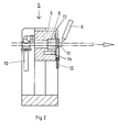
- the slotted tube 1 b then passes in a tool 5, which will be described in more detail with reference to FIG 2. Behind the tool 5 is in the shortest possible distance the Laser welding device 6, in which the longitudinal slot is welded. To the finished optical cable 7 attacks a no longer shown trigger behind which the Cable 7 is then wound on a drum no longer shown.
- the welded metal pipe can be reduced in diameter, stretched and as needed be relieved cooled to an excess length of optical fibers in the metal tube manufacture.
- the slit pipe 1 b is pulled through a diamond ring 8 whose inner diameter is almost equal to the outer diameter of the slot tube 1 b.
- the bore of the Diamond ring 8 is almost cylindrical.
- the diamond ring 8 is in a version 9 arranged, which has a channel system 14 for cooling the diamond ring 8.
- the Channel system 14 is fed by a feed 10 for cooling water.
- the version 9 is in a holder 13 is arranged.
- the tube emerging from the diamond ring 8 is of an annular nozzle 11 surrounded, above the longitudinal slot of the tube, a protective gas in Production direction over the tube blows.
- the protective gas is the nozzle 11 via a Line 12 is supplied.
- the protective gas protects the weld area of the tube until beyond the welding area.
- the device according to the invention take over the form roller groups 2 and 4 the entire molding work in the deformation of the metal strip to a slotted pipe with extremely tight slot.
- the closing and calming of the pipe is done by the Diamond ring 8.
- long life of the diamond ring 8 are also hard Materials for the metal strip possible.
- tubes with a Outer diameter between 1 and 7 mm in lengths of more than 100 km error-free getting produced can tubes with a Outer diameter between 1 and 7 mm in lengths of more than 100 km error-free getting produced.
Landscapes
- Engineering & Computer Science (AREA)
- Mechanical Engineering (AREA)
- Arc Welding In General (AREA)
- Laser Beam Processing (AREA)
Abstract
Description
Claims (5)
- Vorrichtung zur kontinuierlichen Herstellung von längsnahtgeschweißten metallischen Röhrchen mit einem Außendurchmesser von 1 bis 7 mm, bestehend aus einer Ablaufvorrichtung für ein Metallband, einer das Metallband allmählich zu einem Röhrchen mit Längsschlitz formenden Formeinrichtung aus mehreren Formrollensätzen, einem hinter der Formeinrichtung angeordneten Werkzeug, welches die Bandkanten zusammenhält, einer den Längsschlitz verschweißenden Schweißeinrichtung sowie einer an dem geschweißten Röhrchen angreifenden Abzugsvorrichtung, dadurch gekennzeichnet, daß das Werkzeug (5) aus einer wassergekühlten Fassung (9) besteht, in welcher ein Ring (8) aus verschleißfestem Werkstoff angeordnet ist, welchen das ungeschweißte Röhrchen durchläuft.
- Vorrichtung nach Anspruch 1, dadurch gekennzeichnet, daß der Ring (8) aus Diamant besteht.
- Vorrichtung nach Anspruch 1 oder 2, dadurch gekennzeichnet, daß zwischen dem Ring (8) und den Schweißpunkt eine ringförmige Düse (11) angeordnet ist, welche in Fertigungsrichtung ein Schutzgas auf den Längsschlitz bläst.
- Vorrichtung nach einem der Ansprüche 1 bis 3, bei welcher das Metallband zunächst nur an seinen Bandkantenbereichen mit einer Rundung versehen, sodann zu einem U-förmigen Querschnitt und anschließend zu einem Schlitzrohr mit Längsschlitz geformt wird, dadurch gekennzeichnet, daß der äußere Krümmungsradius der Kantenrundungen zwischen 0,05 und 0,5 mm größer ist als der halbe Durchmesser der Öffnung des Ringes (8).
- Vorrichtung nach einem der Ansprüche 1 bis 4, dadurch gekennzeichnet, daß die Fassung (9) in einer Halterung (13) gelagert ist.
Priority Applications (3)
| Application Number | Priority Date | Filing Date | Title |
|---|---|---|---|
| AT04291191T ATE547190T1 (de) | 2004-05-07 | 2004-05-07 | Verfahren zur kontinuierlichen herstellung von längsnahtgeschweissten metallischen röhrchen |
| EP04291191A EP1595610B1 (de) | 2004-05-07 | 2004-05-07 | Verfahren zur kontinuierlichen Herstellung von längsnahtgeschweissten metallischen Röhrchen |
| CN200510067487.6A CN1693004B (zh) | 2004-05-07 | 2005-04-25 | 用于连续制造纵缝焊接的金属细管的方法 |
Applications Claiming Priority (1)
| Application Number | Priority Date | Filing Date | Title |
|---|---|---|---|
| EP04291191A EP1595610B1 (de) | 2004-05-07 | 2004-05-07 | Verfahren zur kontinuierlichen Herstellung von längsnahtgeschweissten metallischen Röhrchen |
Publications (2)
| Publication Number | Publication Date |
|---|---|
| EP1595610A1 true EP1595610A1 (de) | 2005-11-16 |
| EP1595610B1 EP1595610B1 (de) | 2012-02-29 |
Family
ID=34931088
Family Applications (1)
| Application Number | Title | Priority Date | Filing Date |
|---|---|---|---|
| EP04291191A Expired - Lifetime EP1595610B1 (de) | 2004-05-07 | 2004-05-07 | Verfahren zur kontinuierlichen Herstellung von längsnahtgeschweissten metallischen Röhrchen |
Country Status (3)
| Country | Link |
|---|---|
| EP (1) | EP1595610B1 (de) |
| CN (1) | CN1693004B (de) |
| AT (1) | ATE547190T1 (de) |
Families Citing this family (1)
| Publication number | Priority date | Publication date | Assignee | Title |
|---|---|---|---|---|
| CN107405714B (zh) * | 2014-12-31 | 2020-09-01 | 深圳市大富方圆成型技术有限公司 | 一种管材成型机及其气体保护系统 |
Citations (7)
| Publication number | Priority date | Publication date | Assignee | Title |
|---|---|---|---|---|
| GB132680A (de) * | 1900-01-01 | |||
| US1353721A (en) * | 1919-09-30 | 1920-09-21 | Chisholm Douglas Whimster | Closing die or bell for welded tubes |
| DE596506C (de) * | 1932-07-15 | 1934-05-03 | Stahlwerke Roechling Buderus A | Vorrichtung zum Kuehlen von eingefassten Ziehsteinen |
| US2277339A (en) * | 1940-04-18 | 1942-03-24 | Carl V Luginbill | Drawing die |
| EP0115441A2 (de) * | 1983-01-28 | 1984-08-08 | Olin Corporation | Verfahren und Vorrichtung zur Herstellung von Rohren |
| US5143274A (en) * | 1989-07-24 | 1992-09-01 | Societe Foptica S.A. & Commissariat a l'Energie Atomique | Process and apparatus for the manufacture of optical modules |
| EP1230995A2 (de) * | 2001-02-10 | 2002-08-14 | Nexans | Verfahren zur Herstellung längsnahtgeschweisster Rohre |
Family Cites Families (1)
| Publication number | Priority date | Publication date | Assignee | Title |
|---|---|---|---|---|
| DE4434134A1 (de) * | 1994-09-24 | 1996-03-28 | Kabelmetal Electro Gmbh | Verfahren zur Herstellung eines längsnahtgeschweißten Metallrohres |
-
2004
- 2004-05-07 EP EP04291191A patent/EP1595610B1/de not_active Expired - Lifetime
- 2004-05-07 AT AT04291191T patent/ATE547190T1/de active
-
2005
- 2005-04-25 CN CN200510067487.6A patent/CN1693004B/zh not_active Expired - Fee Related
Patent Citations (7)
| Publication number | Priority date | Publication date | Assignee | Title |
|---|---|---|---|---|
| GB132680A (de) * | 1900-01-01 | |||
| US1353721A (en) * | 1919-09-30 | 1920-09-21 | Chisholm Douglas Whimster | Closing die or bell for welded tubes |
| DE596506C (de) * | 1932-07-15 | 1934-05-03 | Stahlwerke Roechling Buderus A | Vorrichtung zum Kuehlen von eingefassten Ziehsteinen |
| US2277339A (en) * | 1940-04-18 | 1942-03-24 | Carl V Luginbill | Drawing die |
| EP0115441A2 (de) * | 1983-01-28 | 1984-08-08 | Olin Corporation | Verfahren und Vorrichtung zur Herstellung von Rohren |
| US5143274A (en) * | 1989-07-24 | 1992-09-01 | Societe Foptica S.A. & Commissariat a l'Energie Atomique | Process and apparatus for the manufacture of optical modules |
| EP1230995A2 (de) * | 2001-02-10 | 2002-08-14 | Nexans | Verfahren zur Herstellung längsnahtgeschweisster Rohre |
Also Published As
| Publication number | Publication date |
|---|---|
| CN1693004B (zh) | 2010-09-08 |
| ATE547190T1 (de) | 2012-03-15 |
| EP1595610B1 (de) | 2012-02-29 |
| CN1692999A (zh) | 2005-11-09 |
Similar Documents
| Publication | Publication Date | Title |
|---|---|---|
| DE3789306T2 (de) | Vorrichtung und Verfahren zur kontinuierlichen Fertigung von bewehrten optischen Kabeln. | |
| EP2674279B2 (de) | Verfahren zum Rollbiegen eines Profils, Profil, Verfahren zur Herstellung gebogener Profilwerkstücke, gebogenes Profilwerkstück, Vorrichtung zum Rollbiegen eines Profils sowie Extrusions- und Rollbiegelinie | |
| EP0313896B1 (de) | Verfahren und Vorrichtung zur Herstellung eines Lichtwellenleiterkabels | |
| EP0703017B1 (de) | Verfahren zur Herstellung eines längsnahtgeschweissten Metallrohres | |
| DE19607705C2 (de) | Drahtlaufsystem für eine Funkenerosionsvorrichtung | |
| DE1957834C3 (de) | Vorrichtung zum Herstellen glatter, dünnwandiger Rohre aus einem kontinuierlichen Blechband | |
| DE4434133A1 (de) | Verfahren zur Herstellung eines optischen Kabels aus einem Metallrohr | |
| EP0701878A1 (de) | Vorrichtung und Verfahren zum Herstellen von Rohren | |
| DE2750640C2 (de) | ||
| DE2708458C2 (de) | Vorrichtung zum gemeinsamen Strangpressen von mindestens zwei Verbundprofilen | |
| DE1107621B (de) | Einrichtung fuer die kontinuierliche Herstellung kleinkalibriger und duennwandiger Nahtrohre | |
| DE2128115A1 (de) | Verfahren und Vorrichtung zur Herstellung glatter Rohre mit dünner oder sehr dünner Wandstärke durch Schweißen | |
| DE2651812A1 (de) | Verfahren und vorrichtung zum kaltformen von langgestreckten stahlwerkstuecken | |
| DE69601357T2 (de) | Automatische ziehvorrichtung | |
| EP1595610B1 (de) | Verfahren zur kontinuierlichen Herstellung von längsnahtgeschweissten metallischen Röhrchen | |
| DE102017109892A1 (de) | Vorrichtung zur Bearbeitung von Kabeln | |
| EP0153495B1 (de) | Verfahren zum Ziehen eines nahtlosen Metallrohres | |
| DE69202306T3 (de) | Rohrwalzwerk, das ein nichtlösen rohrförmigen Materials von der Stange verhindert. | |
| DE3023507C2 (de) | ||
| DE2359368A1 (de) | Verfahren und vorrichtung zur herstellung von verstaerkungselementen kurzer laengenausdehnung | |
| EP1230995B1 (de) | Verfahren und Vorrichtung zur Herstellung längsnahtgeschweisster Rohre | |
| DE10020011A1 (de) | Rippenrohr" | |
| EP0683032A2 (de) | Vorrichtung zum Herstellen einer Rohr-In-Rohr-Leitung | |
| EP1121991B1 (de) | Verfahren zur Herstellung von Metallrohren | |
| EP0473932B1 (de) | Vorrichtung zur Zerkleinerung des Innenspans längsnahtgeschweisster Rohre |
Legal Events
| Date | Code | Title | Description |
|---|---|---|---|
| PUAI | Public reference made under article 153(3) epc to a published international application that has entered the european phase |
Free format text: ORIGINAL CODE: 0009012 |
|
| 17P | Request for examination filed |
Effective date: 20040930 |
|
| AK | Designated contracting states |
Kind code of ref document: A1 Designated state(s): AT BE BG CH CY CZ DE DK EE ES FI FR GB GR HU IE IT LI LU MC NL PL PT RO SE SI SK TR |
|
| AX | Request for extension of the european patent |
Extension state: AL HR LT LV MK |
|
| AKX | Designation fees paid |
Designated state(s): AT BE BG CH CY CZ DE DK EE ES FI FR GB GR HU IE IT LI LU MC NL PL PT RO SE SI SK TR |
|
| RAP1 | Party data changed (applicant data changed or rights of an application transferred) |
Owner name: NEXANS |
|
| GRAP | Despatch of communication of intention to grant a patent |
Free format text: ORIGINAL CODE: EPIDOSNIGR1 |
|
| GRAS | Grant fee paid |
Free format text: ORIGINAL CODE: EPIDOSNIGR3 |
|
| GRAA | (expected) grant |
Free format text: ORIGINAL CODE: 0009210 |
|
| AK | Designated contracting states |
Kind code of ref document: B1 Designated state(s): AT BE BG CH CY CZ DE DK EE ES FI FR GB GR HU IE IT LI LU MC NL PL PT RO SE SI SK TR |
|
| REG | Reference to a national code |
Ref country code: GB Ref legal event code: FG4D Free format text: NOT ENGLISH Ref country code: CH Ref legal event code: EP |
|
| REG | Reference to a national code |
Ref country code: AT Ref legal event code: REF Ref document number: 547190 Country of ref document: AT Kind code of ref document: T Effective date: 20120315 |
|
| REG | Reference to a national code |
Ref country code: IE Ref legal event code: FG4D Free format text: LANGUAGE OF EP DOCUMENT: GERMAN |
|
| REG | Reference to a national code |
Ref country code: DE Ref legal event code: R096 Ref document number: 502004013334 Country of ref document: DE Effective date: 20120426 |
|
| REG | Reference to a national code |
Ref country code: NL Ref legal event code: VDEP Effective date: 20120229 |
|
| PG25 | Lapsed in a contracting state [announced via postgrant information from national office to epo] |
Ref country code: NL Free format text: LAPSE BECAUSE OF FAILURE TO SUBMIT A TRANSLATION OF THE DESCRIPTION OR TO PAY THE FEE WITHIN THE PRESCRIBED TIME-LIMIT Effective date: 20120229 |
|
| PG25 | Lapsed in a contracting state [announced via postgrant information from national office to epo] |
Ref country code: PT Free format text: LAPSE BECAUSE OF FAILURE TO SUBMIT A TRANSLATION OF THE DESCRIPTION OR TO PAY THE FEE WITHIN THE PRESCRIBED TIME-LIMIT Effective date: 20120629 Ref country code: FI Free format text: LAPSE BECAUSE OF FAILURE TO SUBMIT A TRANSLATION OF THE DESCRIPTION OR TO PAY THE FEE WITHIN THE PRESCRIBED TIME-LIMIT Effective date: 20120229 Ref country code: GR Free format text: LAPSE BECAUSE OF FAILURE TO SUBMIT A TRANSLATION OF THE DESCRIPTION OR TO PAY THE FEE WITHIN THE PRESCRIBED TIME-LIMIT Effective date: 20120530 |
|
| REG | Reference to a national code |
Ref country code: IE Ref legal event code: FD4D |
|
| PG25 | Lapsed in a contracting state [announced via postgrant information from national office to epo] |
Ref country code: CY Free format text: LAPSE BECAUSE OF FAILURE TO SUBMIT A TRANSLATION OF THE DESCRIPTION OR TO PAY THE FEE WITHIN THE PRESCRIBED TIME-LIMIT Effective date: 20120229 |
|
| PG25 | Lapsed in a contracting state [announced via postgrant information from national office to epo] |
Ref country code: DK Free format text: LAPSE BECAUSE OF FAILURE TO SUBMIT A TRANSLATION OF THE DESCRIPTION OR TO PAY THE FEE WITHIN THE PRESCRIBED TIME-LIMIT Effective date: 20120229 Ref country code: SI Free format text: LAPSE BECAUSE OF FAILURE TO SUBMIT A TRANSLATION OF THE DESCRIPTION OR TO PAY THE FEE WITHIN THE PRESCRIBED TIME-LIMIT Effective date: 20120229 Ref country code: SE Free format text: LAPSE BECAUSE OF FAILURE TO SUBMIT A TRANSLATION OF THE DESCRIPTION OR TO PAY THE FEE WITHIN THE PRESCRIBED TIME-LIMIT Effective date: 20120229 Ref country code: EE Free format text: LAPSE BECAUSE OF FAILURE TO SUBMIT A TRANSLATION OF THE DESCRIPTION OR TO PAY THE FEE WITHIN THE PRESCRIBED TIME-LIMIT Effective date: 20120229 Ref country code: RO Free format text: LAPSE BECAUSE OF FAILURE TO SUBMIT A TRANSLATION OF THE DESCRIPTION OR TO PAY THE FEE WITHIN THE PRESCRIBED TIME-LIMIT Effective date: 20120229 Ref country code: PL Free format text: LAPSE BECAUSE OF FAILURE TO SUBMIT A TRANSLATION OF THE DESCRIPTION OR TO PAY THE FEE WITHIN THE PRESCRIBED TIME-LIMIT Effective date: 20120229 Ref country code: CZ Free format text: LAPSE BECAUSE OF FAILURE TO SUBMIT A TRANSLATION OF THE DESCRIPTION OR TO PAY THE FEE WITHIN THE PRESCRIBED TIME-LIMIT Effective date: 20120229 Ref country code: IE Free format text: LAPSE BECAUSE OF FAILURE TO SUBMIT A TRANSLATION OF THE DESCRIPTION OR TO PAY THE FEE WITHIN THE PRESCRIBED TIME-LIMIT Effective date: 20120229 |
|
| BERE | Be: lapsed |
Owner name: NEXANS Effective date: 20120531 |
|
| PG25 | Lapsed in a contracting state [announced via postgrant information from national office to epo] |
Ref country code: SK Free format text: LAPSE BECAUSE OF FAILURE TO SUBMIT A TRANSLATION OF THE DESCRIPTION OR TO PAY THE FEE WITHIN THE PRESCRIBED TIME-LIMIT Effective date: 20120229 |
|
| PG25 | Lapsed in a contracting state [announced via postgrant information from national office to epo] |
Ref country code: MC Free format text: LAPSE BECAUSE OF NON-PAYMENT OF DUE FEES Effective date: 20120531 |
|
| PLBE | No opposition filed within time limit |
Free format text: ORIGINAL CODE: 0009261 |
|
| STAA | Information on the status of an ep patent application or granted ep patent |
Free format text: STATUS: NO OPPOSITION FILED WITHIN TIME LIMIT |
|
| GBPC | Gb: european patent ceased through non-payment of renewal fee |
Effective date: 20120529 |
|
| 26N | No opposition filed |
Effective date: 20121130 |
|
| PG25 | Lapsed in a contracting state [announced via postgrant information from national office to epo] |
Ref country code: BE Free format text: LAPSE BECAUSE OF NON-PAYMENT OF DUE FEES Effective date: 20120531 |
|
| REG | Reference to a national code |
Ref country code: FR Ref legal event code: ST Effective date: 20130131 |
|
| REG | Reference to a national code |
Ref country code: DE Ref legal event code: R097 Ref document number: 502004013334 Country of ref document: DE Effective date: 20121130 |
|
| PG25 | Lapsed in a contracting state [announced via postgrant information from national office to epo] |
Ref country code: GB Free format text: LAPSE BECAUSE OF NON-PAYMENT OF DUE FEES Effective date: 20120529 Ref country code: FR Free format text: LAPSE BECAUSE OF NON-PAYMENT OF DUE FEES Effective date: 20120531 |
|
| PG25 | Lapsed in a contracting state [announced via postgrant information from national office to epo] |
Ref country code: BG Free format text: LAPSE BECAUSE OF FAILURE TO SUBMIT A TRANSLATION OF THE DESCRIPTION OR TO PAY THE FEE WITHIN THE PRESCRIBED TIME-LIMIT Effective date: 20120529 |
|
| PG25 | Lapsed in a contracting state [announced via postgrant information from national office to epo] |
Ref country code: ES Free format text: LAPSE BECAUSE OF FAILURE TO SUBMIT A TRANSLATION OF THE DESCRIPTION OR TO PAY THE FEE WITHIN THE PRESCRIBED TIME-LIMIT Effective date: 20120609 |
|
| PG25 | Lapsed in a contracting state [announced via postgrant information from national office to epo] |
Ref country code: TR Free format text: LAPSE BECAUSE OF FAILURE TO SUBMIT A TRANSLATION OF THE DESCRIPTION OR TO PAY THE FEE WITHIN THE PRESCRIBED TIME-LIMIT Effective date: 20120229 |
|
| PG25 | Lapsed in a contracting state [announced via postgrant information from national office to epo] |
Ref country code: LU Free format text: LAPSE BECAUSE OF NON-PAYMENT OF DUE FEES Effective date: 20120507 |
|
| PG25 | Lapsed in a contracting state [announced via postgrant information from national office to epo] |
Ref country code: HU Free format text: LAPSE BECAUSE OF FAILURE TO SUBMIT A TRANSLATION OF THE DESCRIPTION OR TO PAY THE FEE WITHIN THE PRESCRIBED TIME-LIMIT Effective date: 20040507 |
|
| PGFP | Annual fee paid to national office [announced via postgrant information from national office to epo] |
Ref country code: IT Payment date: 20150513 Year of fee payment: 12 |
|
| PG25 | Lapsed in a contracting state [announced via postgrant information from national office to epo] |
Ref country code: IT Free format text: LAPSE BECAUSE OF NON-PAYMENT OF DUE FEES Effective date: 20160507 |
|
| PGFP | Annual fee paid to national office [announced via postgrant information from national office to epo] |
Ref country code: DE Payment date: 20230519 Year of fee payment: 20 Ref country code: CH Payment date: 20230605 Year of fee payment: 20 |
|
| PGFP | Annual fee paid to national office [announced via postgrant information from national office to epo] |
Ref country code: AT Payment date: 20230522 Year of fee payment: 20 |
|
| REG | Reference to a national code |
Ref country code: DE Ref legal event code: R071 Ref document number: 502004013334 Country of ref document: DE |
|
| REG | Reference to a national code |
Ref country code: CH Ref legal event code: PL |
|
| REG | Reference to a national code |
Ref country code: AT Ref legal event code: MK07 Ref document number: 547190 Country of ref document: AT Kind code of ref document: T Effective date: 20240507 |