EP1595185B1 - Electric automation device and method for adjusting the functions of the electric automation device - Google Patents
Electric automation device and method for adjusting the functions of the electric automation device Download PDFInfo
- Publication number
- EP1595185B1 EP1595185B1 EP04705379A EP04705379A EP1595185B1 EP 1595185 B1 EP1595185 B1 EP 1595185B1 EP 04705379 A EP04705379 A EP 04705379A EP 04705379 A EP04705379 A EP 04705379A EP 1595185 B1 EP1595185 B1 EP 1595185B1
- Authority
- EP
- European Patent Office
- Prior art keywords
- automation device
- application module
- basic
- automation
- functions
- Prior art date
- Legal status (The legal status is an assumption and is not a legal conclusion. Google has not performed a legal analysis and makes no representation as to the accuracy of the status listed.)
- Expired - Lifetime
Links
- 230000006870 function Effects 0.000 title claims abstract description 52
- 238000000034 method Methods 0.000 title claims description 19
- 238000004891 communication Methods 0.000 claims abstract description 16
- 238000012545 processing Methods 0.000 claims description 12
- 230000004913 activation Effects 0.000 claims description 3
- 238000012360 testing method Methods 0.000 abstract description 9
- 238000004519 manufacturing process Methods 0.000 abstract description 3
- 230000008569 process Effects 0.000 description 4
- 230000006978 adaptation Effects 0.000 description 3
- 230000008901 benefit Effects 0.000 description 2
- 230000005540 biological transmission Effects 0.000 description 2
- 230000008859 change Effects 0.000 description 2
- 230000010354 integration Effects 0.000 description 2
- 230000001681 protective effect Effects 0.000 description 2
- 238000010276 construction Methods 0.000 description 1
- 238000013499 data model Methods 0.000 description 1
- 238000013461 design Methods 0.000 description 1
- 238000005516 engineering process Methods 0.000 description 1
- 230000001747 exhibiting effect Effects 0.000 description 1
- 238000011990 functional testing Methods 0.000 description 1
- 238000012544 monitoring process Methods 0.000 description 1
- 238000013519 translation Methods 0.000 description 1
Images
Classifications
-
- G—PHYSICS
- G05—CONTROLLING; REGULATING
- G05B—CONTROL OR REGULATING SYSTEMS IN GENERAL; FUNCTIONAL ELEMENTS OF SUCH SYSTEMS; MONITORING OR TESTING ARRANGEMENTS FOR SUCH SYSTEMS OR ELEMENTS
- G05B19/00—Programme-control systems
- G05B19/02—Programme-control systems electric
- G05B19/04—Programme control other than numerical control, i.e. in sequence controllers or logic controllers
- G05B19/042—Programme control other than numerical control, i.e. in sequence controllers or logic controllers using digital processors
Definitions
- the invention relates to an electrical automation device with a controller controlled by a computer.
- Electrical automation devices such as electrical protection or field control devices of the station automation technology, usually have computer-controlled control devices.
- control devices By means of a software installed in the control device, the respective functions of such an automation device can be defined and executed.
- the software is usually completely embedded in the control device of the electrical automation device and forms with this a so-called "embedded system".
- Another example of known automation devices of the type mentioned above are software-controlled manufacturing robots.
- an electrical protection device in particular a distance protection device
- instructions relating to the distance protection functions of the automation device and communication instructions may be contained in the software, for example.
- An exact definition of the functions of the programmable controller is made by the user of the programmable controller already at the time of ordering the programmable controller at the manufacturer.
- EP 1 256 861 For example, a method for programming programmable logic controllers will be described. The programming takes place via a Web Access Module that is connected to a personal computer via the Internet
- the invention has for its object to provide an electrical automation device that is flexible and adaptable to predetermined functions with reduced test cost.
- an electrical automation device of the type mentioned above that a computer hardware is equipped to form a basic automation device with control software that has an operating system, device drivers and communication modules comprehensive base function area, and that the basic automation device is completed via a software interface with the basic function area connectable any application modules to the automation device.
- the essential advantage of the automation device according to the invention is that initially similar, with all automation devices common components (eg operating system, device drivers, communication modules) equipped basic automation devices produced in series and using various application modules as desired - so flexible - can be adapted to required functions.
- This adaptation completes the respective basic automation device in each case to the actual automation device.
- the application blocks can be integrated into the control software in a modular manner via the software interface.
- the final functions of the automation device are determined by the selection of these application blocks.
- the entire basic automation device remains largely unchanged during the generation of any automation devices; Therefore, no further functional tests have to be carried out with respect to the components of the basic automation device when using proven basic automation devices, which considerably reduces the test effort for the respective automation device.
- different application components are correspondingly present for the various functions of the automation device.
- the application modules represent according to this embodiment advantageously self-contained functional units, each of which assumes a function (eg external communication, protection functions, time switching) of the electrical automation device. Since tried and tested application modules can also be used as application components, the test effort for the final automation device is significantly reduced by this embodiment.
- the electrical automation device may be, for example, an electrical protection or control device.
- Such devices include a variety of different functions, so that an inventive design with flexible function adaptation is of great interest here.
- the object of the invention is also to provide a method with which an electrical automation device can be made flexible with respect to predetermined functions.
- a method for adjusting the functions of an electrical automation device with a computer having control device wherein the following steps are performed: transferring at least one modified using an output application module application module to a basic automation device, with a computer hardware and control software having a basic function area comprising an operating system, device drivers, and communication modules, and executing setup instructions of the at least one modified application device completing the electrical automation device, the at least one modified application device setting at least one function of the automation device into the control software is involved.
- an automation device can be made flexibly adapted to predetermined functions using modular application components which describe a single function of the automation device in each case. Furthermore, it is thereby advantageously possible, in the presence of a single modified application module to produce a whole series of similar automation devices; For this purpose, the modified application block (or one copy thereof) must only be transferred to all automation basic devices of this series.
- At least one configuration and setting instructions exhibiting output application modules are loaded into a memory area of the basic automation device simulating data processing device and the configuration statements of the at least one output application module by means of the data processing device to form the modified application module in setting the functions be carried out of the electrical automation device.
- a data processing device By executing already in the output application module configuration instructions on a data processing device that simulates a basic automation device, advantageously all essential settings regarding the various - formed by the respective application modules - functions of the automation device to be generated already made outside the automation base unit become. Namely, a data processing device usually offers a much more comfortable environment which is more powerful in terms of its functionality than the basic automation devices.
- the XML format is used for the at least one output application module.
- XML format can be easily generate structured data and instructions for the control software.
- a further solution of the object with regard to the method is given by a method for setting the functions of an electrical automation device with a computer having control means, wherein the following steps are performed: loading at least one configuration and setting instructions having output application module in a memory area of the control device, cooperating with control software of an automation base unit containing a computer hardware, wherein the control software comprises a base function area comprising an operating system, device drivers and communication modules, executing the configuration instructions of the at least one output application unit by means of the control means, forming a modified application unit setting the Functions of the electrical automation device and execution of the adjustment instructions of the at least one modified A Application module with completion of the electrical automation device, wherein the at least one modified application module is integrated by setting at least one function of the automation device in the control software.
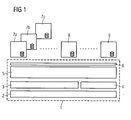
- FIG. 1 schematically shows the structure of an electrical automation device.
- a so-called basic automation device 1 comprises a computer hardware 2, which is equipped with a control software with a basic functional area, consisting of an operating system 3, device drivers 4 and communication modules 5.
- computer hardware 2 in this case both a single computing device, such as a microprocessor, and a system of several devices, such as different processors and co-processors, may function.
- the control software also has a software interface 6.
- an automation base unit 1 does not yet have any functions specific to the actual automation device; On the other hand, it represents a kind of basic device for automation devices.
- 6 individual can be used via the software interface
- Application blocks 7a, 7b, 7c, 8 and 9 are connected to the basic functional area of the control software.
- an electrical protection device for the protection and monitoring of electrical equipment such as electrical power lines or electrical machines is assumed.
- the electrical protection device is initially present in the form of an automation base unit 1.
- Such an automation base unit 1 does not yet have any functions specific to an electrical protection device. Rather, it is a basic device that forms a flexible basis for any adaptable with regard to its functions protection device.
- a manufacturer of electrical protection devices for example, to equip a (already existing) basic electrical automation device 1 comparatively uncomplicated with a desired range of functions by a customer.
- the basic automation device 1 In order to complete the basic automation device 1 to a protective device with its respective specific functions, it can be equipped with different types of application modules 7a, 7b, 7c, 8, 9, each of which represents a single function of the electrical protection device. These application modules 7a, 7b, 7c, 8, 9 can be connected via the software interface 6 to the basic functional area of the control software.
- API application program interface
- the application modules 7a, 7b and 7c include individual protection algorithms and protection methods of the electrical protection device, such. B. an overcurrent protection.
- Another application module 8 may be a recording module for recording selected voltage or current waveforms, in turn another application module 9 may include communication modalities with an external device, such as a transducer.
- the reduced test effort for the electrical protection device or the electrical automation device is of particular advantage.
- an automation device according to the prior art which is specially equipped with a specially developed complete software package for this purpose, a test run of all functions and components (hardware and software) of the automation device to be performed, so in the automation device according to the invention, for example Automation base unit 1 already exist in a tested and proven form, so that for this area including computer hardware 2, operating system 3, device drivers 4 and 4 communication modules thus the test effort is saved.
- the information content of the application modules may, for example, be in a form based on the XML format.
- data and information can be structured in a device-independent form.
- a "translation" of the XML format can be ensured, for example, by the communication modules 5 or the operating system 2 of the basic functional area of the control software.
- an electrical automation device can be used when manufacturers and users of such automation devices have agreed on a uniform standard for the representation and modeling of data and information as well as their communication between individual devices. This is expected to be met with the IEC 61850 standard.
- the IEC standard 61850 regulates u. a. the data model of the scope of automation devices, so that when using standards compliant configurations compatibility of devices and control software from different manufacturers is advantageously secured.
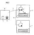
- FIG. 2 schematically shows a method for producing or setting the specific functions of an electrical automation device. The method is intended as an example for the application module 7a according to FIG. 1 be explained.
- An initially present (software) output application module 10 contains configuration instructions 13 and adjustment instructions 14. This output application module 10 is loaded in a storage area of a data processing device 12 in a charging process indicated by a dashed arrow 11.
- the data processing device 12 which may be, for example, a correspondingly equipped PC, moreover simulates an automation basic unit 1 (cf. FIG. 1 ) with a computer hardware 2, an operating system 3, device drivers 4 and communication modules 5.
- the configuration instructions 13 of the output application module 10 are executed, which is indicated by a further arrow 15.
- the output application module 10 is integrated via the software interface 6 into the control software of the simulated automation basic unit.
- adjustments are made, for example, with regard to the activation of the output application module 10, its operating display and essential parameters. Currently, such an operation takes place at the manufacturer of an electrical automation device.
- the output application module 10 After the output application module 10 has been connected in this way to the basic functional area of the control software as part of the simulated basic automation unit, it represents a modified application module. In its present form, this is transferred to a (real) automation basic unit 1 (cf. FIG. 1 ) (see arrow 16). There, the modified application module 7a can be connected in a simple manner via the software interface 6 to the basic functional area of the control software. This is particularly advantageous that the once on the data processing device 12 settings must not be repeated again on the automation basic unit 1. The modified application module 7a is transferred to the basic automation device 1 as it was after execution of the configuration instructions 13 on the data processing device 12.
- the setting instructions 14 already present in the output application module 10 and also in the modified application module 7 a can be executed in order to make the last settings.
- the user of an automation device has access to these setting instructions 14, for example to adapt a special function to external conditions.
- the user can also change such settings later, so that, for example, in this way an electrical protection device can be adapted to changed line conditions of a monitored power transmission line, such as a change in the cable length or the resistance of the power transmission line.
- the process described can be repeated several times with ever new automation basic devices.
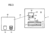
- FIG. 3 it can also be provided to load the output application module 10 directly into the automation basic unit 1 and to execute both the configuration instructions 13 and the setting instructions 14 there.
- the output application module is loaded in a memory area 22 of the control device 23 of the automation basic unit 1 in a charging process illustrated by a dashed arrow 21.
- the configuration instructions 13 of the output application module 10 are executed, as indicated by arrow 24.
- a determination of the scope of the automation device by selecting the appropriate output application blocks and integration of the respective output application block in the automation base unit 1 instead.
- settings are made regarding the activation of the output application block 10, its operator display and essential parameters. This process turns the output application block into a modified application block.
- the adjustment instructions 14 of the modified application module are executed with the same basic automation device and thus the settings for adaptation to external conditions are made (as also in connection with FIG. 2 explains), which completes the automation base unit to the actual automation device.
- the automation basic device is a comparatively easy-to-use basic automation device.
- an automation base unit can be formed by an industrial PC.
- automation devices with the desired functions can also be generated on the user side by selecting different output application blocks and their integration into the basic automation device.
- the user can derive the necessary output application modules from special software libraries in the form of standardized application modules.
Abstract
Description
Die Erfindung betrifft ein elektrisches Automatisierungsgerät mit einer von einem Rechner gesteuerten Steuereinrichtung.The invention relates to an electrical automation device with a controller controlled by a computer.
Elektrische Automatisierungsgeräte, wie beispielsweise elektrische Schutz- oder Feldleitgeräte der Stationsautomatisierungstechnik, weisen üblicherweise rechnergesteuerte Steuereinrichtungen auf. Mit Hilfe einer in der Steuereinrichtung installierten Software können die jeweiligen Funktionen eines solchen Automatisierungsgerätes festgelegt und ausgeführt werden. Die Software ist üblicherweise in die Steuereinrichtung des elektrischen Automatisierungsgerätes vollständig eingebettet und bildet mit dieser ein sogenanntes "Embedded System". Ein weiteres Beispiel für bekannte Automatisierungsgeräte der oben angegebenen Art sind softwaregesteuerte Fertigungsroboter.Electrical automation devices, such as electrical protection or field control devices of the station automation technology, usually have computer-controlled control devices. By means of a software installed in the control device, the respective functions of such an automation device can be defined and executed. The software is usually completely embedded in the control device of the electrical automation device and forms with this a so-called "embedded system". Another example of known automation devices of the type mentioned above are software-controlled manufacturing robots.
Nimmt man als elektrisches Automatisierungsgerät beispielsweise ein elektrisches Schutzgerät, spezieller ein Distanzschutzgerät, an, so können in der Software beispielsweise Anweisungen bezüglich der Distanzschutzfunktionen des Automatisierungsgerätes und Kommunikationsanweisungen enthalten sein. Eine genaue Festlegung der Funktionen des Automatisierungsgerätes wird durch den Anwender des Automatisierungsgerätes bereits zum Zeitpunkt der Bestellung des Automatisierungsgerätes bei dessen Hersteller getroffen.If, for example, an electrical protection device, in particular a distance protection device, is assumed as the electrical automation device, instructions relating to the distance protection functions of the automation device and communication instructions may be contained in the software, for example. An exact definition of the functions of the programmable controller is made by the user of the programmable controller already at the time of ordering the programmable controller at the manufacturer.
Bisherige elektrische Automatisierungsgeräte, insbesondere im Bereich der Schutz- und Feldleitgeräte, werden vom Hersteller mit einem gerätebezogenen Software-Paket ganzheitlich entwickelt und müssen im vollen Umfang auf Richtigkeit und Zuverlässigkeit aller Funktionen getestet werden. Ein solches Vorgehen ist mit einem erheblichen Kosten- und Zeitaufwand verbunden.Previous electrical automation devices, especially in the field of protection and bay controllers, are from the manufacturer are holistically developed with a device-related software package and must be fully tested for the correctness and reliability of all functions. Such a procedure is associated with a considerable cost and time.
In der europäischen Patentanmeldung
Ausgehend von einem elektrischen Automatisierungsgerät der eben beschriebenen Art liegt der Erfindung die Aufgabe zugrunde, ein elektrisches Automatisierungsgerät anzugeben, das flexibel und mit reduziertem Testaufwand an vorgegebene Funktionen anpassbar ist.Based on an electrical automation device of the type just described, the invention has for its object to provide an electrical automation device that is flexible and adaptable to predetermined functions with reduced test cost.
Zur Lösung dieser Aufgabe wird bei einem elektrischen Automatisierungsgerät der oben genannten Art vorgeschlagen, dass eine Rechner-Hardware unter Bildung eines Automatisierungs-Grundgerätes mit einer Steuersoftware ausgestattet ist, die einen ein Betriebssystem, Gerätetreiber und Kommunikationsmodule umfassenden Basisfunktionsbereich aufweist, und dass das Automatisierungs-Grundgerät durch über eine Softwareschnittstelle mit dem Basisfunktionsbereich verbindbare beliebige Anwendungsbausteine zum Automatisierungsgerät vervollständigt ist.To solve this problem is proposed in an electrical automation device of the type mentioned above that a computer hardware is equipped to form a basic automation device with control software that has an operating system, device drivers and communication modules comprehensive base function area, and that the basic automation device is completed via a software interface with the basic function area connectable any application modules to the automation device.
Der wesentliche Vorteil des erfindungsgemäßen Automatisierungsgerätes ist, dass zunächst gleichartige, mit allen Automatisierungsgeräten gemeinsamen Komponenten (z.B. Betriebssystem, Gerätetreiber, Kommunikationsmodule) ausgestattete Automatisierungs-Grundgeräte in Serie erzeugt und unter Verwendung von verschiedenen Anwendungsbausteinen beliebig - also flexibel - an geforderte Funktionen angepasst werden können. Durch diese Anpassung wird das jeweilige Automatisierungs-Grundgerät jeweils zum eigentlichen Automatisierungsgerät komplettiert. Als Gerätetreiber werden in diesem Zusammenhang Programme zur softwaretechnischen Ansteuerung weiterer elektronischer Geräte des jeweiligen elektrischen Automatisierungsgerätes angesehen; Kommunikationsmodule regeln z. B. die interne Gerätekommunikation zwischen dem Basisfunktionsbereich der Steuersoftware und beliebigen über die Softwareschnittstelle mit dem Basisfunktionsbereich verbindbaren Anwendungsbausteinen.The essential advantage of the automation device according to the invention is that initially similar, with all automation devices common components (eg operating system, device drivers, communication modules) equipped basic automation devices produced in series and using various application modules as desired - so flexible - can be adapted to required functions. This adaptation completes the respective basic automation device in each case to the actual automation device. As a device driver in this context Programs for software control of other electronic devices of the respective electrical automation device viewed; Communication modules regulate z. B. the internal device communication between the basic function area of the control software and any connectable via the software interface with the basic function area application blocks.
Die Anwendungsbausteine können dabei modulartig über die Softwareschnittstelle in die Steuersoftware eingebunden werden. Die endgültigen Funktionen des Automatisierungsgerätes werden durch die Auswahl dieser Anwendungsbausteine bestimmt.The application blocks can be integrated into the control software in a modular manner via the software interface. The final functions of the automation device are determined by the selection of these application blocks.
Das gesamte Automatisierungs-Grundgerät bleibt bei der Erzeugung beliebiger Automatisierungsgeräte weitgehend unverändert; daher müssen - bei Verwendung erprobter Automatisierungs-Grundgeräte - keine weiteren Funktionstests bezüglich der Komponenten des Automatisierungs-Grundgerätes durchgeführt werden, was den Testaufwand für das jeweilige Automatisierungsgerät deutlich reduziert.The entire basic automation device remains largely unchanged during the generation of any automation devices; Therefore, no further functional tests have to be carried out with respect to the components of the basic automation device when using proven basic automation devices, which considerably reduces the test effort for the respective automation device.
Gemäß einer vorteilhaften Ausführungsform des erfindungsgemäßen Automatisierungsgerätes sind für die verschiedenen Funktionen des Automatisierungsgerätes entsprechend verschiedene Anwendungsbausteine vorhanden. Die Anwendungsbausteine stellen nach dieser Ausführungsform vorteilhafterweise für sich abgeschlossene Funktionseinheiten dar, die jeweils eine Funktion (z.B. externe Kommunikation, Schutzfunktionen, Zeitschaltungen) des elektrischen Automatisierungsgerätes übernehmen. Da als Anwendungsbausteine zudem erprobte Anwendungsbausteine eingesetzt werden können, verringert sich der Testaufwand für das endgültige Automatisierungsgerät durch diese Ausführungsform nochmals deutlich.According to an advantageous embodiment of the automation device according to the invention, different application components are correspondingly present for the various functions of the automation device. The application modules represent according to this embodiment advantageously self-contained functional units, each of which assumes a function (eg external communication, protection functions, time switching) of the electrical automation device. Since tried and tested application modules can also be used as application components, the test effort for the final automation device is significantly reduced by this embodiment.
Das elektrische Automatisierungsgerät kann beispielsweise ein elektrisches Schutz- oder Leitgerät sein. Solche Geräte beinhalten eine Vielzahl verschiedenster Funktionen, so dass eine erfindungsgemäße Ausgestaltung mit flexibler Funktionsanpassung hierbei von großem Interesse ist.The electrical automation device may be, for example, an electrical protection or control device. Such devices include a variety of different functions, so that an inventive design with flexible function adaptation is of great interest here.
Aufgabe der Erfindung ist es auch, ein Verfahren anzugeben, mit dem ein elektrisches Automatisierungsgerät bezüglich vorgegebener Funktionen flexibel hergestellt werden kann.The object of the invention is also to provide a method with which an electrical automation device can be made flexible with respect to predetermined functions.
Zur Lösung dieser Aufgabe wird ein Verfahren zum Einstellen der Funktionen eines elektrischen Automatisierungsgerätes mit einer einen Rechner aufweisenden Steuereinrichtung, wobei folgende Schritte durchgeführt werden: Übertragen zumindest eines unter Verwendung eines Ausgangs-Anwendungsbausteins modifizierten Anwendungsbausteins an ein Automatisierungs-Grundgerät, das mit einer Rechner-Hardware und einer Steuersoftware, die einen ein Betriebssystem, Gerätetreiber und Kommunikationsmodule umfassenden Basisfunktionsbereich aufweist, ausgestattet ist, und Ausführen von Einstellungsanweisungen des zumindest einen modifizierten Anwendungsbausteins unter Vervollständigung des elektrischen Automatisierungsgerätes, wobei der zumindest eine modifizierte Anwendungsbaustein unter Einstellen zumindest einer Funktion des Automatisierungsgerätes in die Steuersoftware eingebunden wird.To achieve this object, a method for adjusting the functions of an electrical automation device with a computer having control device, wherein the following steps are performed: transferring at least one modified using an output application module application module to a basic automation device, with a computer hardware and control software having a basic function area comprising an operating system, device drivers, and communication modules, and executing setup instructions of the at least one modified application device completing the electrical automation device, the at least one modified application device setting at least one function of the automation device into the control software is involved.
Auf diese Weise kann unter Verwendung von modulartigen jeweils eine einzige Funktion des Automatisierungsgerätes beschreibenden modifizierten Anwendungsbausteinen ein Automatisierungsgerät flexibel an vorgegebene Funktionen angepasst hergestellt werden. Ferner ist es hierdurch vorteilhaft möglich, bei Vorliegen eines einzigen modifizierten Anwendungsbausteines eine ganze Serie gleichartiger Automatisierungsgeräte zu erzeugen; hierzu muss der modifizierte Anwendungsbaustein (oder jeweils eine Kopie davon) nur an alle Automatisierungs-Grundgeräte dieser Serie übertragen werden.In this way, an automation device can be made flexibly adapted to predetermined functions using modular application components which describe a single function of the automation device in each case. Furthermore, it is thereby advantageously possible, in the presence of a single modified application module to produce a whole series of similar automation devices; For this purpose, the modified application block (or one copy thereof) must only be transferred to all automation basic devices of this series.
Vorteilhafterweise kann zum Erzeugen des modifizierten Anwendungsbausteins zumindest ein Konfigurations- und Einstellungsanweisungen aufweisender Ausgangs-Anwendungsbausteins in einen Speicherbereich einer das Automatisierungs-Grundgerät simulierenden Datenverarbeitungseinrichtung geladen werden und die Konfigurationsanweisungen des zumindest einen Ausgangs-Anwendungsbausteins mittels der Datenverarbeitungseinrichtung unter Bilden des modifizierten Anwendungsbausteins bei Festlegen der Funktionen des elektrischen Automatisierungsgerätes ausgeführt werden.Advantageously, for generating the modified application module at least one configuration and setting instructions exhibiting output application modules are loaded into a memory area of the basic automation device simulating data processing device and the configuration statements of the at least one output application module by means of the data processing device to form the modified application module in setting the functions be carried out of the electrical automation device.
Durch die Ausführung von in dem Ausgangs-Anwendungsbaustein bereits enthaltenen Konfigurationsanweisungen auf einer Datenverarbeitungseinrichtung, die ein Automatisierungs-Grundgerät simuliert, können vorteilhafterweise alle wesentlichen Einstellungen bezüglich der verschiedenen - durch die jeweiligen Anwendungsbausteine gebildeten - Funktionen des zu erzeugenden Automatisierungsgerätes bereits außerhalb des Automatisierungs-Grundgerätes vorgenommen werden. Eine Datenverarbeitungseinrichtung bietet nämlich üblicherweise eine deutlich komfortablere und bezüglich ihrer Funktionalität leistungsfähigere Umgebung als die Automatisierungs-Grundgeräte.By executing already in the output application module configuration instructions on a data processing device that simulates a basic automation device, advantageously all essential settings regarding the various - formed by the respective application modules - functions of the automation device to be generated already made outside the automation base unit become. Namely, a data processing device usually offers a much more comfortable environment which is more powerful in terms of its functionality than the basic automation devices.
Weiterhin kann vorteilhaft vorgesehen sein, dass für den zumindest einen Ausgangs-Anwendungsbausteins das XML-Format verwendet wird. Im XML-Format lassen sich auf einfache Weise strukturierte Daten und Anweisungen für die Steuersoftware erzeugen.Furthermore, it can be advantageously provided that the XML format is used for the at least one output application module. In XML format can be easily generate structured data and instructions for the control software.
Eine weitere Lösung der Aufgabe bezüglich des Verfahrens wird durch ein Verfahren zum Einstellen der Funktionen eines elektrischen Automatisierungsgerätes mit einer einen Rechner aufweisenden Steuereinrichtung angegeben, wobei folgende Schritte durchgeführt werden: Laden zumindest eines Konfigurations- und Einstellungsanweisungen aufweisenden Ausgangs-Anwendungsbausteins in einen Speicherbereich der Steuereinrichtung, die mit einer Bteuersoftware eines eine Rechner-hardware enthaltenden Automatisierungs-Grundgerätes zusammen wirkt, wobei die Steuersoftware einen ein Betriebssystem, Gerätetreiber und Kommunikationsmodule umfassenden Basisfunktionsbereich aufweist, Ausführen der Konfigurationsanweisungen des zumindest einen Ausgangs-Anwendungsbausteins mittels der Steuereinrichtung unter Bilden eines modifizierten Anwendungsbausteins bei Festlegen der Funktionen des elektrischen Automatisierungsgerätes und Ausführen der Einstellungsanweisungen des zumindest einen modifizierten Anwendungsbausteins unter Vervollständigung des elektrischen Automatisierungsgerätes, wobei der zumindest eine modifizierte Anwendungsbaustein unter Einstellen zumindest einer Funktion des Automatisierungsgerätes in die Steuersoftware eingebunden wird.A further solution of the object with regard to the method is given by a method for setting the functions of an electrical automation device with a computer having control means, wherein the following steps are performed: loading at least one configuration and setting instructions having output application module in a memory area of the control device, cooperating with control software of an automation base unit containing a computer hardware, wherein the control software comprises a base function area comprising an operating system, device drivers and communication modules, executing the configuration instructions of the at least one output application unit by means of the control means, forming a modified application unit setting the Functions of the electrical automation device and execution of the adjustment instructions of the at least one modified A Application module with completion of the electrical automation device, wherein the at least one modified application module is integrated by setting at least one function of the automation device in the control software.
Auf diese Weise können vorteilhaft insbesondere solche Automatisierungs-Grundgeräte bezüglich ihrer Funktionen zu einem Automatisierungsgerät vervollständigt werden, die ähnlich leistungsfähige Bedienmöglichkeiten und Funktionalitäten wie eine übliche Datenverarbeitungseinrichtung aufweisen.In this way, in particular those automation basic devices can be advantageously completed with respect to their functions to an automation device, which have similarly powerful operating options and functionalities as a conventional data processing device.
Zur weiteren Erläuterung der Erfindung sind in
Figur 1- schematisch der Aufbau eines Ausführungsbeispiels des erfindungsgemäßen eines elektrischen Automati- sierungsgerätes, in
Figur 2- schematisch ein Ausführungsbeispiel eines erfin- dungsgemäßen Verfahrens zum Einstellen der Funktio- nen eines elektrischen Automatisierungsgerätes und in
Figur 3- ein weiteres Ausführungsbeispiel eines weiteren er- findungsgemäßen Verfahrens zum Einstellen der Funk- tionen eines elektrischen Automatisierungsgerätes
- FIG. 1
- schematically the structure of an embodiment of the invention of an electrical automation sierungsgerätes, in
- FIG. 2
- schematically an embodiment of an inventive method for adjusting the functions of an electrical automation device and in
- FIG. 3
- a further embodiment of another inventive method for adjusting the functions of an electrical automation device
Ein solches Automatisierungs-Grundgerät 1 weist allerdings noch keine für das eigentliche Automatisierungsgerät spezifischen Funktionen auf; es stellt hingegen eine Art Basisgerät für Automatisierungsgeräte dar. Zur Realisierung spezifischer Funktionen können über die Softwareschnittstelle 6 einzelne Anwendungsbausteine 7a, 7b, 7c, 8 und 9 mit dem Basisfunktionsbereich der Steuersoftware verbunden werden.However, such an
Dies soll anhand des folgenden Beispiels näher erläutert werden. Als elektrisches Automatisierungsgerät werde ein elektrisches Schutzgerät zum Schutz und zur Überwachung von elektrischen Betriebsmitteln wie elektrischen Energieversorgungsleitungen oder elektrischen Maschinen angenommen. Das elektrische Schutzgerät liege zunächst in der Form eines Automatisierungs-Grundgerätes 1 vor. Ein solches Automatisierungs-Grundgerät 1 weist noch keine für ein elektrisches Schutzgerät spezifischen Funktionen auf. Vielmehr stellt es ein Basisgerät dar, das eine flexible Grundlage für ein beliebig hinsichtlich seiner Funktionen anpassbares Schutzgerät bildet. So ist es für einen Hersteller elektrischer Schutzgeräte beispielsweise möglich, ein (bereits vorhandenes) elektrisches Automatisierungs-Grundgerät 1 vergleichsweise unkompliziert mit einem von einem Kunden gewünschten Funktionsumfang auszustatten.This will be explained in more detail with reference to the following example. As an electrical automation device, an electrical protection device for the protection and monitoring of electrical equipment such as electrical power lines or electrical machines is assumed. The electrical protection device is initially present in the form of an
Um das Automatisierungs-Grundgerät 1 zu einem Schutzgerät mit seinen jeweiligen spezifischen Funktionen zu vervollständigen, lässt es sich nämlich mit verschiedenartigen Anwendungsbausteinen 7a, 7b, 7c, 8, 9 ausstatten, die jeweils für sich eine einzelne Funktion des elektrischen Schutzgerätes darstellen. Diese Anwendungsbausteine 7a, 7b, 7c, 8, 9 lassen sich über die Softwareschnittstelle 6 mit dem Basisfunktionsbereich der Steuersoftware verbinden. Solche Softwareschnittstellen (auch "API" = "application program interface" genannt) sind dem Fachmann an sich bekannt; sie können entweder aus einer einzigen zentralen Softwareschnittstelle oder beispielsweise auch aus verschiedenen verteilten Softwareteilschnittstellen gebildet sein.In order to complete the
Im Falles des Schutzgerätes können beispielsweise die Anwendungsbausteine 7a, 7b und 7c (vgl.
Neben dem modulartigen und flexiblen Aufbau ist insbesondere der reduzierte Testaufwand für das elektrische Schutzgerät bzw. das elektrische Automatisierungsgerät von besonderem Vorteil. Muss nämlich bei einem Automatisierungsgerät nach dem Stand der Technik, das je nach Anwendungsfall speziell mit einem eigens hierfür entwickelten kompletten Softwarepaket ausgestattet ist, ein Testlauf aller Funktionen und Komponenten (Hardware und Software) des Automatisierungsgerätes durchgeführt werden, so kann bei dem erfindungsgemäßen Automatisierungsgerät beispielsweise das Automatisierungs-Grundgerät 1 bereits in einer getesteten und erprobten Form vorliegen, so dass für diesen Bereich inklusive Rechner-Hardware 2, Betriebssystem 3, Gerätetreibern 4 und Kommunikationsmodulen 4 folglich der Testaufwand eingespart wird. Ferner ist es auch möglich, die einzelnen Anwendungsbausteine 7a, 7b, 7c, 8, 9 in einer vorkonfektionierten und getesteten Form bereits vorliegen zu haben, so dass nur nach der Vervollständigung des Automatisierungs-Grundgerätes 1 durch die entsprechenden Anwendungsbausteine 7a, 7b, 7c, 8, 9 zum Automatisierungsgerät ein Funktionstest der spezifischen Gerätefunktionen durchgeführt werden muss. Hierdurch lassen sich kosten- und zeitaufwendige Testläufe deutlich reduzieren.In addition to the modular and flexible structure, in particular the reduced test effort for the electrical protection device or the electrical automation device is of particular advantage. Namely, in an automation device according to the prior art, which is specially equipped with a specially developed complete software package for this purpose, a test run of all functions and components (hardware and software) of the automation device to be performed, so in the automation device according to the invention, for example
Der Informationsinhalt der Anwendungsbausteine kann beispielsweise in einer auf dem XML-Format beruhenden Form vorliegen. In dem XLM-Format lassen sich in einer geräteunabhängigen Form Daten und Informationen strukturiert angeben. Eine "Übersetzung" des XML-Formats kann beispielsweise durch die Kommunikationsmodule 5 oder das Betriebssystem 2 des Basisfunktionsbereiches der Steuersoftware gewährleistet werden.The information content of the application modules may, for example, be in a form based on the XML format. In the XLM format, data and information can be structured in a device-independent form. A "translation" of the XML format can be ensured, for example, by the communication modules 5 or the
Besonders vorteilhaft kann der beschriebene Aufbau eines elektrischen Automatisierungsgerätes dann eingesetzt werden, wenn sich Hersteller und Nutzer solcher Automatisierungsgeräte auf einen einheitlichen Standard für die Darstellung und die Modellierung von Daten und Informationen sowie deren Kommunikation zwischen einzelnen Geräten geeinigt haben. Dies wird voraussichtliche mit der Norm IEC 61850 erfüllt. Die IEC Norm 61850 regelt u. a. das Datenmodell des Anwendungsbereiches von Automatisierungsgeräten, so dass bei Verwendung normkonformer Ausgestaltungen eine Kompatibilität von Geräten und Steuersoftware unterschiedlicher Hersteller vorteilhaft gesichert ist.Particularly advantageously, the described construction of an electrical automation device can be used when manufacturers and users of such automation devices have agreed on a uniform standard for the representation and modeling of data and information as well as their communication between individual devices. This is expected to be met with the IEC 61850 standard. The IEC standard 61850 regulates u. a. the data model of the scope of automation devices, so that when using standards compliant configurations compatibility of devices and control software from different manufacturers is advantageously secured.
Ein zunächst vorliegender (Software-) Ausgangs-Anwendungsbaustein 10 enthalte Konfigurationsanweisungen 13 und Einstellungsanweisungen 14. Dieser Ausgangs-Anwendungsbaustein 10 wird in einem durch einen strichlierten Pfeil 11 angedeuteten Ladevorgang in einen Speicherbereich einer Datenverarbeitungseinrichtung 12 geladen.An initially present (software)
Die Datenverarbeitungseinrichtung 12, die beispielsweise ein entsprechend eingerichteter PC sein kann, simuliert darüber hinaus ein Automatisierungs-Grundgerät 1 (vgl.
In einem nun folgenden Konfigurationsschritt werden die Konfigurationsanweisungen 13 des Ausgangs-Anwendungsbausteins 10 ausgeführt, was durch einen weiteren Pfeil 15 angedeutet wird. Durch das Ausführen der Konfigurationsanweisungen 13 wird der Ausgangs-Anwendungsbaustein 10 über die Softwareschnittstelle 6 in die Steuersoftware des simulierten Automatisierungs-Grundgerätes eingebunden. Gleichzeitig werden Einstellungen beispielsweise bezüglich der Aktivierung des Ausgangs-Anwendungsbausteins 10, seiner Bedienungsanzeige und wesentlicher Parameter durchgeführt. Derzeit findet ein solcher Vorgang beim Hersteller eines elektrischen Automatisierungsgerätes statt.In a subsequent configuration step, the
Nachdem im Rahmen des simulierten Automatisierungs-Grundgerätes der Ausgangsanwendungsbaustein 10 auf diese Weise mit dem Basisfunktionsbereich der Steuersoftware verbunden ist, stellt er einen modifizierten Anwendungsbaustein dar. Dieser wird in der nun vorliegenden Form an ein (reales) Automatisierungs-Grundgerät 1 (vgl.
Nach Ausführen dieser letzten Einstellungsanweisungen 14 ist das Automatisierungs-Grundgerät zum eigentlichen Automatisierungsgerät mit seinem geforderten Funktionsumfang vervollständigt.After executing these
Zum Erzeugen mehrerer gleichartiger Automatisierungsgeräte aus gleichartigen Automatisierungsgrundgeräten 1 kann der beschriebene Vorgang mehrfach mit immer neuen AutomatisierungsGrundgeräten wiederholt werden. Besonders vorteilhaft ist es aber, ein einziges Mal, wie oben beschrieben, einen modifizierten Anwendungsbaustein (beispielsweise 7a) zu erzeugen und diesen an mehrere Automatisierungs-Grundgeräte 1 zu übertragen. Auf diese Weise kann der Erzeugungsaufwand mehrerer gleichartiger modifizierter Anwendungsbausteine eingespart werden.For generating a plurality of similar automation devices from similar
Alternativ zu dem eben erläuterten Einstellungsverfahren kann auch vorgesehen sein, den Ausgangs-Anwendungsbaustein 10 direkt in das Automatisierungs-Grundgerät 1 zu laden und dort sowohl die Konfigurationsanweisungen 13 als auch die Einstellungsanweisungen 14 auszuführen. Dies ist in
Nachfolgend werden mit demselben Automatisierungs-Grundgerät die Einstellungsanweisungen 14 des modifizierten Anwendungsbausteins ausgeführt und somit die Einstellungen zur Anpassung an äußere Gegebenheiten vorgenommen (wie auch im Zusammenhang mit
Eine solche Vorgehensweise eignet sich insbesondere, wenn als Automatisierungs-Grundgerät ein vergleichsweise gut zu bedienendes Automatisierungs-Grundgerät vorliegt. Beispielsweise kann ein solches Automatisierungs-Grundgerät durch einen Industrie-PC gebildet sein. In diesem Fall können auch auf der Anwenderseite durch Auswahl verschiedener Ausgangs-Anwendungsbausteine und deren Integration in das Automatisierungs-Grundgerät Automatisierungsgeräte mit den gewünschten Funktionen erzeugt werden. Die notwendigen Ausgangs-Anwendungsbausteine kann der Anwender hierbei beispielsweise speziellen Software-Bibliotheken in Form standardisierter Anwendungsbausteine entnehmen.Such a procedure is particularly suitable if the automation basic device is a comparatively easy-to-use basic automation device. For example, such an automation base unit can be formed by an industrial PC. In this case, automation devices with the desired functions can also be generated on the user side by selecting different output application blocks and their integration into the basic automation device. For example, the user can derive the necessary output application modules from special software libraries in the form of standardized application modules.
Claims (2)
- Method for adjusting the functions of an electric automation device which has a control unit comprising a computer, the following steps being carried out:- loading at least one starting application module (10), comprising configuration and adjustment instructions (13, 14), into a memory area of a data processing unit (12) simulating a basic automation device;- forming a modified application module (7a) from the at least one starting application module (10) by performing the configuration instructions (13) of the at least one starting application module (10) by means of the data processing unit (12), the starting application module (10) being incorporated via a software interface (6) in a control software component of the basic automation device simulated by the data processing unit, and adjustments being carried out with respect to an activation of the starting application module (10), the operator display thereof and the parameters thereof, and the modified application module (7a) representing a specific function of the one automation device;- transferring the modified application module (7a) to the basic automation device (1), which is equipped with a computer hardware component (2) and a control software component, which has a basic functional area comprising an operating system (3), device drivers (4) and communication modules (5);- connecting the at least one modified application module (7a) via a software interface (6) to the basic functional area of the control software component; and- performing the adjustment instructions (14) so as to adapt the specific function of the at least one modified application module (7a) to external conditions while completing the electric automation device.
- Method according to Claim 1, characterized in that the XML format is used for the at least one starting application module (10).
Applications Claiming Priority (3)
| Application Number | Priority Date | Filing Date | Title |
|---|---|---|---|
| DE2003107332 DE10307332A1 (en) | 2003-02-17 | 2003-02-17 | Electrical automation device and method for setting the functions of the electrical automation device |
| DE10307332 | 2003-02-17 | ||
| PCT/DE2004/000158 WO2004072743A2 (en) | 2003-02-17 | 2004-01-27 | Modular soft sps implemented on a computer, and method for adjusting the function of said soft sps |
Publications (2)
| Publication Number | Publication Date |
|---|---|
| EP1595185A2 EP1595185A2 (en) | 2005-11-16 |
| EP1595185B1 true EP1595185B1 (en) | 2011-08-31 |
Family
ID=32797590
Family Applications (1)
| Application Number | Title | Priority Date | Filing Date |
|---|---|---|---|
| EP04705379A Expired - Lifetime EP1595185B1 (en) | 2003-02-17 | 2004-01-27 | Electric automation device and method for adjusting the functions of the electric automation device |
Country Status (4)
| Country | Link |
|---|---|
| EP (1) | EP1595185B1 (en) |
| CN (1) | CN1799010A (en) |
| DE (1) | DE10307332A1 (en) |
| WO (1) | WO2004072743A2 (en) |
Families Citing this family (5)
| Publication number | Priority date | Publication date | Assignee | Title |
|---|---|---|---|---|
| DE502006008834D1 (en) * | 2006-03-29 | 2011-03-10 | Siemens Ag | FIELD DEVICE |
| EP2138913B1 (en) * | 2008-06-25 | 2011-10-26 | ABB Research Ltd. | Flexible intelligent electronic device |
| CN102598629B (en) * | 2009-06-03 | 2016-08-03 | Abb技术有限公司 | For issuing the method and system of data from intelligent electronic device |
| US8942970B2 (en) | 2009-06-26 | 2015-01-27 | Abb Research Ltd. | Method for configuring an intelligent electronic device and a substation automation system |
| US10130305B2 (en) | 2016-04-22 | 2018-11-20 | Under Armour, Inc. | Device and methods for automated testing |
Family Cites Families (8)
| Publication number | Priority date | Publication date | Assignee | Title |
|---|---|---|---|---|
| DE3808135A1 (en) * | 1988-03-11 | 1989-09-28 | Kloeckner Moeller Elektrizit | Stored-program control system |
| WO1997003389A1 (en) * | 1995-07-11 | 1997-01-30 | Elin Energieanwendung Gmbh | Process for generating a user-specific logic diagram for programmable controllers (sps) |
| CA2232305A1 (en) * | 1995-09-19 | 1997-03-27 | Siemens Aktiengesellschaft | Automation system for the open-loop and closed-loop control of machines and plants in the plastics industry |
| DE19740775A1 (en) * | 1997-09-17 | 1999-03-18 | Focke & Co | Control system for especially palletizing systems with robots |
| DE19826169A1 (en) * | 1998-06-13 | 1999-12-16 | Kaeser Kompressoren Gmbh | Electronic control for compressed air and vacuum generation systems |
| DE19845764A1 (en) * | 1998-10-05 | 2000-04-13 | Siemens Ag | Programmable logic controller using data management via a network computer and method for operating a programmable logic controller |
| DE10021838A1 (en) * | 2000-05-05 | 2001-11-08 | Focke & Co | Device for manufacturing products and method for controlling such a device |
| US8131827B2 (en) * | 2001-05-09 | 2012-03-06 | Rockwell Automation Technologies, Inc. | PLC with web-accessible program development software |
-
2003
- 2003-02-17 DE DE2003107332 patent/DE10307332A1/en not_active Withdrawn
-
2004
- 2004-01-27 CN CN 200480004414 patent/CN1799010A/en active Pending
- 2004-01-27 WO PCT/DE2004/000158 patent/WO2004072743A2/en active Application Filing
- 2004-01-27 EP EP04705379A patent/EP1595185B1/en not_active Expired - Lifetime
Also Published As
| Publication number | Publication date |
|---|---|
| WO2004072743A2 (en) | 2004-08-26 |
| DE10307332A1 (en) | 2004-09-02 |
| CN1799010A (en) | 2006-07-05 |
| EP1595185A2 (en) | 2005-11-16 |
| WO2004072743A3 (en) | 2006-03-09 |
Similar Documents
| Publication | Publication Date | Title |
|---|---|---|
| DE19781804B4 (en) | Device for simulating a real-time process control | |
| EP2801872B1 (en) | Test device for testing a virtual control device | |
| EP2685382B1 (en) | Method and device for producing and testing a control device program | |
| DE102010043661A1 (en) | Vehicle control unit testing device for use in hardware in-the-loop simulator, has computing unit and signal generating card that are connected with serial bus interface for receiving and/or sending time and angle synchronous messages | |
| DE3632569C2 (en) | ||
| DE10303489A1 (en) | Motor vehicle control unit software testing, whereby the software is simulated using a test system that at least partially simulates the control path of a control unit | |
| DE2228881A1 (en) | Automatic diagnostic examiner | |
| DE102010014070A1 (en) | Method and test bench for testing hybrid propulsion systems or subcomponents thereof | |
| EP1906377A1 (en) | System and method for integrating a process control system into a training simulator | |
| EP3130970A1 (en) | Method for connecting an input/output interface of a test device set up to develop a control device | |
| EP3451202B1 (en) | Method for generating a model of a technical system which can be run on a test device and a test device | |
| WO2013075909A1 (en) | Method for the automatic generation of simulation models using circuit diagrams | |
| DE102011009583B4 (en) | Easy creation of a remote control sequence for measuring devices | |
| EP1595185B1 (en) | Electric automation device and method for adjusting the functions of the electric automation device | |
| EP2343611A1 (en) | Method for computer supported generation of an executable control program and corresponding configuration device | |
| DE102014219711A1 (en) | Method for power plant simulation | |
| EP0862763B1 (en) | Simulator unit for simulating a peripheral unit of a modular programmable controller | |
| EP2446331A1 (en) | Emulation of an automation system | |
| DE4121637A1 (en) | METHOD AND DEVICE FOR TESTING CONTROL UNITS | |
| DE3318410A1 (en) | Method for changing and optimising data and program cycles for programmed control devices in motor vehicles | |
| WO2014079548A1 (en) | System for providing an individually configured safety switching relay | |
| WO2006035038A2 (en) | Method for testing control device software for a control device | |
| DE10232659A1 (en) | Process and configurator for creating a system concept from a number of system components | |
| EP3732608B1 (en) | Method for the computer-aided parameterisation of a technical system | |
| DE102013010783A1 (en) | Method and control device for testing an automation solution based on a PLC control |
Legal Events
| Date | Code | Title | Description |
|---|---|---|---|
| PUAI | Public reference made under article 153(3) epc to a published international application that has entered the european phase |
Free format text: ORIGINAL CODE: 0009012 |
|
| 17P | Request for examination filed |
Effective date: 20050624 |
|
| AK | Designated contracting states |
Kind code of ref document: A2 Designated state(s): AT BE BG CH CY CZ DE DK EE ES FI FR GB GR HU IE IT LI LU MC NL PT RO SE SI SK TR |
|
| AX | Request for extension of the european patent |
Extension state: AL LT LV MK |
|
| PUAK | Availability of information related to the publication of the international search report |
Free format text: ORIGINAL CODE: 0009015 |
|
| DAX | Request for extension of the european patent (deleted) | ||
| RBV | Designated contracting states (corrected) |
Designated state(s): DE FR GB IT |
|
| 17Q | First examination report despatched |
Effective date: 20071122 |
|
| GRAP | Despatch of communication of intention to grant a patent |
Free format text: ORIGINAL CODE: EPIDOSNIGR1 |
|
| GRAS | Grant fee paid |
Free format text: ORIGINAL CODE: EPIDOSNIGR3 |
|
| GRAA | (expected) grant |
Free format text: ORIGINAL CODE: 0009210 |
|
| AK | Designated contracting states |
Kind code of ref document: B1 Designated state(s): DE FR GB IT |
|
| REG | Reference to a national code |
Ref country code: GB Ref legal event code: FG4D Free format text: NOT ENGLISH |
|
| REG | Reference to a national code |
Ref country code: DE Ref legal event code: R096 Ref document number: 502004012840 Country of ref document: DE Effective date: 20111027 |
|
| PLBE | No opposition filed within time limit |
Free format text: ORIGINAL CODE: 0009261 |
|
| STAA | Information on the status of an ep patent application or granted ep patent |
Free format text: STATUS: NO OPPOSITION FILED WITHIN TIME LIMIT |
|
| 26N | No opposition filed |
Effective date: 20120601 |
|
| REG | Reference to a national code |
Ref country code: DE Ref legal event code: R097 Ref document number: 502004012840 Country of ref document: DE Effective date: 20120601 |
|
| REG | Reference to a national code |
Ref country code: DE Ref legal event code: R084 Ref document number: 502004012840 Country of ref document: DE Effective date: 20130110 |
|
| REG | Reference to a national code |
Ref country code: FR Ref legal event code: PLFP Year of fee payment: 13 |
|
| REG | Reference to a national code |
Ref country code: FR Ref legal event code: PLFP Year of fee payment: 14 |
|
| REG | Reference to a national code |
Ref country code: FR Ref legal event code: PLFP Year of fee payment: 15 |
|
| PGFP | Annual fee paid to national office [announced via postgrant information from national office to epo] |
Ref country code: FR Payment date: 20230113 Year of fee payment: 20 |
|
| PGFP | Annual fee paid to national office [announced via postgrant information from national office to epo] |
Ref country code: IT Payment date: 20230126 Year of fee payment: 20 Ref country code: GB Payment date: 20230202 Year of fee payment: 20 Ref country code: DE Payment date: 20220620 Year of fee payment: 20 |
|
| REG | Reference to a national code |
Ref country code: DE Ref legal event code: R071 Ref document number: 502004012840 Country of ref document: DE |
|
| REG | Reference to a national code |
Ref country code: GB Ref legal event code: PE20 Expiry date: 20240126 |