EP1595185B1 - Automate programmable electrique et procede pour regler les fonctions de cet automate programmable electrique - Google Patents
Automate programmable electrique et procede pour regler les fonctions de cet automate programmable electrique Download PDFInfo
- Publication number
- EP1595185B1 EP1595185B1 EP04705379A EP04705379A EP1595185B1 EP 1595185 B1 EP1595185 B1 EP 1595185B1 EP 04705379 A EP04705379 A EP 04705379A EP 04705379 A EP04705379 A EP 04705379A EP 1595185 B1 EP1595185 B1 EP 1595185B1
- Authority
- EP
- European Patent Office
- Prior art keywords
- automation device
- application module
- basic
- automation
- functions
- Prior art date
- Legal status (The legal status is an assumption and is not a legal conclusion. Google has not performed a legal analysis and makes no representation as to the accuracy of the status listed.)
- Expired - Lifetime
Links
- 230000006870 function Effects 0.000 title claims abstract description 52
- 238000000034 method Methods 0.000 title claims description 19
- 238000004891 communication Methods 0.000 claims abstract description 16
- 238000012545 processing Methods 0.000 claims description 12
- 230000004913 activation Effects 0.000 claims description 3
- 238000012360 testing method Methods 0.000 abstract description 9
- 238000004519 manufacturing process Methods 0.000 abstract description 3
- 230000008569 process Effects 0.000 description 4
- 230000006978 adaptation Effects 0.000 description 3
- 230000008901 benefit Effects 0.000 description 2
- 230000005540 biological transmission Effects 0.000 description 2
- 230000008859 change Effects 0.000 description 2
- 230000010354 integration Effects 0.000 description 2
- 230000001681 protective effect Effects 0.000 description 2
- 238000010276 construction Methods 0.000 description 1
- 238000013499 data model Methods 0.000 description 1
- 238000013461 design Methods 0.000 description 1
- 238000005516 engineering process Methods 0.000 description 1
- 230000001747 exhibiting effect Effects 0.000 description 1
- 238000011990 functional testing Methods 0.000 description 1
- 238000012544 monitoring process Methods 0.000 description 1
- 238000013519 translation Methods 0.000 description 1
Images
Classifications
-
- G—PHYSICS
- G05—CONTROLLING; REGULATING
- G05B—CONTROL OR REGULATING SYSTEMS IN GENERAL; FUNCTIONAL ELEMENTS OF SUCH SYSTEMS; MONITORING OR TESTING ARRANGEMENTS FOR SUCH SYSTEMS OR ELEMENTS
- G05B19/00—Programme-control systems
- G05B19/02—Programme-control systems electric
- G05B19/04—Programme control other than numerical control, i.e. in sequence controllers or logic controllers
- G05B19/042—Programme control other than numerical control, i.e. in sequence controllers or logic controllers using digital processors
Definitions
- the invention relates to an electrical automation device with a controller controlled by a computer.
- Electrical automation devices such as electrical protection or field control devices of the station automation technology, usually have computer-controlled control devices.
- control devices By means of a software installed in the control device, the respective functions of such an automation device can be defined and executed.
- the software is usually completely embedded in the control device of the electrical automation device and forms with this a so-called "embedded system".
- Another example of known automation devices of the type mentioned above are software-controlled manufacturing robots.
- an electrical protection device in particular a distance protection device
- instructions relating to the distance protection functions of the automation device and communication instructions may be contained in the software, for example.
- An exact definition of the functions of the programmable controller is made by the user of the programmable controller already at the time of ordering the programmable controller at the manufacturer.
- EP 1 256 861 For example, a method for programming programmable logic controllers will be described. The programming takes place via a Web Access Module that is connected to a personal computer via the Internet
- the invention has for its object to provide an electrical automation device that is flexible and adaptable to predetermined functions with reduced test cost.
- an electrical automation device of the type mentioned above that a computer hardware is equipped to form a basic automation device with control software that has an operating system, device drivers and communication modules comprehensive base function area, and that the basic automation device is completed via a software interface with the basic function area connectable any application modules to the automation device.
- the essential advantage of the automation device according to the invention is that initially similar, with all automation devices common components (eg operating system, device drivers, communication modules) equipped basic automation devices produced in series and using various application modules as desired - so flexible - can be adapted to required functions.
- This adaptation completes the respective basic automation device in each case to the actual automation device.
- the application blocks can be integrated into the control software in a modular manner via the software interface.
- the final functions of the automation device are determined by the selection of these application blocks.
- the entire basic automation device remains largely unchanged during the generation of any automation devices; Therefore, no further functional tests have to be carried out with respect to the components of the basic automation device when using proven basic automation devices, which considerably reduces the test effort for the respective automation device.
- different application components are correspondingly present for the various functions of the automation device.
- the application modules represent according to this embodiment advantageously self-contained functional units, each of which assumes a function (eg external communication, protection functions, time switching) of the electrical automation device. Since tried and tested application modules can also be used as application components, the test effort for the final automation device is significantly reduced by this embodiment.
- the electrical automation device may be, for example, an electrical protection or control device.
- Such devices include a variety of different functions, so that an inventive design with flexible function adaptation is of great interest here.
- the object of the invention is also to provide a method with which an electrical automation device can be made flexible with respect to predetermined functions.
- a method for adjusting the functions of an electrical automation device with a computer having control device wherein the following steps are performed: transferring at least one modified using an output application module application module to a basic automation device, with a computer hardware and control software having a basic function area comprising an operating system, device drivers, and communication modules, and executing setup instructions of the at least one modified application device completing the electrical automation device, the at least one modified application device setting at least one function of the automation device into the control software is involved.
- an automation device can be made flexibly adapted to predetermined functions using modular application components which describe a single function of the automation device in each case. Furthermore, it is thereby advantageously possible, in the presence of a single modified application module to produce a whole series of similar automation devices; For this purpose, the modified application block (or one copy thereof) must only be transferred to all automation basic devices of this series.
- At least one configuration and setting instructions exhibiting output application modules are loaded into a memory area of the basic automation device simulating data processing device and the configuration statements of the at least one output application module by means of the data processing device to form the modified application module in setting the functions be carried out of the electrical automation device.
- a data processing device By executing already in the output application module configuration instructions on a data processing device that simulates a basic automation device, advantageously all essential settings regarding the various - formed by the respective application modules - functions of the automation device to be generated already made outside the automation base unit become. Namely, a data processing device usually offers a much more comfortable environment which is more powerful in terms of its functionality than the basic automation devices.
- the XML format is used for the at least one output application module.
- XML format can be easily generate structured data and instructions for the control software.
- a further solution of the object with regard to the method is given by a method for setting the functions of an electrical automation device with a computer having control means, wherein the following steps are performed: loading at least one configuration and setting instructions having output application module in a memory area of the control device, cooperating with control software of an automation base unit containing a computer hardware, wherein the control software comprises a base function area comprising an operating system, device drivers and communication modules, executing the configuration instructions of the at least one output application unit by means of the control means, forming a modified application unit setting the Functions of the electrical automation device and execution of the adjustment instructions of the at least one modified A Application module with completion of the electrical automation device, wherein the at least one modified application module is integrated by setting at least one function of the automation device in the control software.
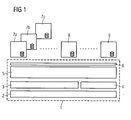
- FIG. 1 schematically shows the structure of an electrical automation device.
- a so-called basic automation device 1 comprises a computer hardware 2, which is equipped with a control software with a basic functional area, consisting of an operating system 3, device drivers 4 and communication modules 5.
- computer hardware 2 in this case both a single computing device, such as a microprocessor, and a system of several devices, such as different processors and co-processors, may function.
- the control software also has a software interface 6.
- an automation base unit 1 does not yet have any functions specific to the actual automation device; On the other hand, it represents a kind of basic device for automation devices.
- 6 individual can be used via the software interface
- Application blocks 7a, 7b, 7c, 8 and 9 are connected to the basic functional area of the control software.
- an electrical protection device for the protection and monitoring of electrical equipment such as electrical power lines or electrical machines is assumed.
- the electrical protection device is initially present in the form of an automation base unit 1.
- Such an automation base unit 1 does not yet have any functions specific to an electrical protection device. Rather, it is a basic device that forms a flexible basis for any adaptable with regard to its functions protection device.
- a manufacturer of electrical protection devices for example, to equip a (already existing) basic electrical automation device 1 comparatively uncomplicated with a desired range of functions by a customer.
- the basic automation device 1 In order to complete the basic automation device 1 to a protective device with its respective specific functions, it can be equipped with different types of application modules 7a, 7b, 7c, 8, 9, each of which represents a single function of the electrical protection device. These application modules 7a, 7b, 7c, 8, 9 can be connected via the software interface 6 to the basic functional area of the control software.
- API application program interface
- the application modules 7a, 7b and 7c include individual protection algorithms and protection methods of the electrical protection device, such. B. an overcurrent protection.
- Another application module 8 may be a recording module for recording selected voltage or current waveforms, in turn another application module 9 may include communication modalities with an external device, such as a transducer.
- the reduced test effort for the electrical protection device or the electrical automation device is of particular advantage.
- an automation device according to the prior art which is specially equipped with a specially developed complete software package for this purpose, a test run of all functions and components (hardware and software) of the automation device to be performed, so in the automation device according to the invention, for example Automation base unit 1 already exist in a tested and proven form, so that for this area including computer hardware 2, operating system 3, device drivers 4 and 4 communication modules thus the test effort is saved.
- the information content of the application modules may, for example, be in a form based on the XML format.
- data and information can be structured in a device-independent form.
- a "translation" of the XML format can be ensured, for example, by the communication modules 5 or the operating system 2 of the basic functional area of the control software.
- an electrical automation device can be used when manufacturers and users of such automation devices have agreed on a uniform standard for the representation and modeling of data and information as well as their communication between individual devices. This is expected to be met with the IEC 61850 standard.
- the IEC standard 61850 regulates u. a. the data model of the scope of automation devices, so that when using standards compliant configurations compatibility of devices and control software from different manufacturers is advantageously secured.
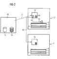
- FIG. 2 schematically shows a method for producing or setting the specific functions of an electrical automation device. The method is intended as an example for the application module 7a according to FIG. 1 be explained.
- An initially present (software) output application module 10 contains configuration instructions 13 and adjustment instructions 14. This output application module 10 is loaded in a storage area of a data processing device 12 in a charging process indicated by a dashed arrow 11.
- the data processing device 12 which may be, for example, a correspondingly equipped PC, moreover simulates an automation basic unit 1 (cf. FIG. 1 ) with a computer hardware 2, an operating system 3, device drivers 4 and communication modules 5.
- the configuration instructions 13 of the output application module 10 are executed, which is indicated by a further arrow 15.
- the output application module 10 is integrated via the software interface 6 into the control software of the simulated automation basic unit.
- adjustments are made, for example, with regard to the activation of the output application module 10, its operating display and essential parameters. Currently, such an operation takes place at the manufacturer of an electrical automation device.
- the output application module 10 After the output application module 10 has been connected in this way to the basic functional area of the control software as part of the simulated basic automation unit, it represents a modified application module. In its present form, this is transferred to a (real) automation basic unit 1 (cf. FIG. 1 ) (see arrow 16). There, the modified application module 7a can be connected in a simple manner via the software interface 6 to the basic functional area of the control software. This is particularly advantageous that the once on the data processing device 12 settings must not be repeated again on the automation basic unit 1. The modified application module 7a is transferred to the basic automation device 1 as it was after execution of the configuration instructions 13 on the data processing device 12.
- the setting instructions 14 already present in the output application module 10 and also in the modified application module 7 a can be executed in order to make the last settings.
- the user of an automation device has access to these setting instructions 14, for example to adapt a special function to external conditions.
- the user can also change such settings later, so that, for example, in this way an electrical protection device can be adapted to changed line conditions of a monitored power transmission line, such as a change in the cable length or the resistance of the power transmission line.
- the process described can be repeated several times with ever new automation basic devices.
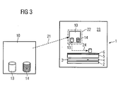
- FIG. 3 it can also be provided to load the output application module 10 directly into the automation basic unit 1 and to execute both the configuration instructions 13 and the setting instructions 14 there.
- the output application module is loaded in a memory area 22 of the control device 23 of the automation basic unit 1 in a charging process illustrated by a dashed arrow 21.
- the configuration instructions 13 of the output application module 10 are executed, as indicated by arrow 24.
- a determination of the scope of the automation device by selecting the appropriate output application blocks and integration of the respective output application block in the automation base unit 1 instead.
- settings are made regarding the activation of the output application block 10, its operator display and essential parameters. This process turns the output application block into a modified application block.
- the adjustment instructions 14 of the modified application module are executed with the same basic automation device and thus the settings for adaptation to external conditions are made (as also in connection with FIG. 2 explains), which completes the automation base unit to the actual automation device.
- the automation basic device is a comparatively easy-to-use basic automation device.
- an automation base unit can be formed by an industrial PC.
- automation devices with the desired functions can also be generated on the user side by selecting different output application blocks and their integration into the basic automation device.
- the user can derive the necessary output application modules from special software libraries in the form of standardized application modules.
Abstract
Claims (2)
- Procédé de réglage des fonctions d'un appareil d'automatisation électrique, qui comporte un dispositif de commande ayant un ordinateur, dans lequel on effectue les stades suivantes :- on charge au moins un module ( 10 ) d'application de sortie ayant des instructions ( 13, 14 ) de configuration et de réglage dans une zone de mémoire d'un dispositif ( 12 ) de traitement de données simulant un appareil de base d'automatisation ;- on forme un module ( 7a ) d'application modifié à partir du au moins un module ( 10 ) d'application de sortie, en exécutant les instructions ( 13 ) de configuration du au moins un module ( 10 ) d'application de sortie au moyen du dispositif ( 12 ) de traitement de données, le module ( 10 ) d'application de sortie étant incorporé par une interface logicielle dans un logiciel de commande de l'appareil de base d'automatisation simulé par le dispositif de traitement de données et des réglages concernant une activation du module ( 10 ) d'application de sortie, son indication de service et ses paramètres sont effectués et dans lequel le module ( 7a ) d'application modifié représente une fonction spécifique du un appareil d'automatisation ;on transmet le module 7a d'application modifié à l'appareil (1) de base d'automatisation, qui est équipé d'un matériel d'ordinateur et d'un logiciel de commande, qui comprend une zone de fonction de base comprenant un système ( 3 ) d'exploittion, des pilotes ( 4 ) d'appareil et des modules ( 5 ) de communication ;- on relie le au moins un module ( 7a ) d'application modifiée par une interface ( 6 ) logicielle à la zone de fonction de base du logiciel de commande ;- on exécute les instructions ( 14 ) de réglage pour l'adaptation de la fonction spécifique du au moins un module ( 7a ) d'application modifié à des conditions extérieures en complétant l'appareil d'automatisation électrique.
- Procédé suivant la revendication 1,
caractérisé- en ce qu'on utilise le format XML pour le au moins un module ( 10 ) d'application de sortie.
Applications Claiming Priority (3)
| Application Number | Priority Date | Filing Date | Title |
|---|---|---|---|
| DE10307332 | 2003-02-17 | ||
| DE2003107332 DE10307332A1 (de) | 2003-02-17 | 2003-02-17 | Elektrisches Automatisierungsgerät und Verfahren zum Einstellen der Funktionen des Elektrischen Automatisierungsgerätes |
| PCT/DE2004/000158 WO2004072743A2 (fr) | 2003-02-17 | 2004-01-27 | Automate programmable electrique et procede pour regler les fonctions de cet automate programmable electrique |
Publications (2)
| Publication Number | Publication Date |
|---|---|
| EP1595185A2 EP1595185A2 (fr) | 2005-11-16 |
| EP1595185B1 true EP1595185B1 (fr) | 2011-08-31 |
Family
ID=32797590
Family Applications (1)
| Application Number | Title | Priority Date | Filing Date |
|---|---|---|---|
| EP04705379A Expired - Lifetime EP1595185B1 (fr) | 2003-02-17 | 2004-01-27 | Automate programmable electrique et procede pour regler les fonctions de cet automate programmable electrique |
Country Status (4)
| Country | Link |
|---|---|
| EP (1) | EP1595185B1 (fr) |
| CN (1) | CN1799010A (fr) |
| DE (1) | DE10307332A1 (fr) |
| WO (1) | WO2004072743A2 (fr) |
Families Citing this family (5)
| Publication number | Priority date | Publication date | Assignee | Title |
|---|---|---|---|---|
| EP1999521B1 (fr) * | 2006-03-29 | 2011-01-26 | Siemens Aktiengesellschaft | Appareil de terrain |
| ATE530962T1 (de) | 2008-06-25 | 2011-11-15 | Abb Research Ltd | Flexibles intelligentes elektronisches gerät |
| CN102598629B (zh) * | 2009-06-03 | 2016-08-03 | Abb技术有限公司 | 用于从智能电子装置发布数据的方法与系统 |
| US8942970B2 (en) | 2009-06-26 | 2015-01-27 | Abb Research Ltd. | Method for configuring an intelligent electronic device and a substation automation system |
| US10130305B2 (en) | 2016-04-22 | 2018-11-20 | Under Armour, Inc. | Device and methods for automated testing |
Family Cites Families (8)
| Publication number | Priority date | Publication date | Assignee | Title |
|---|---|---|---|---|
| DE3808135A1 (de) * | 1988-03-11 | 1989-09-28 | Kloeckner Moeller Elektrizit | Speicherprogrammierbares steuerungssystem |
| WO1997003389A1 (fr) * | 1995-07-11 | 1997-01-30 | Elin Energieanwendung Gmbh | Procede pour l'etablissement d'un schema logique specifique d'un utilisateur pour automates programmables (sps) |
| DE59606596D1 (de) * | 1995-09-19 | 2001-04-19 | Siemens Ag | Automatisierungssystem für das steuern und regeln von maschinen und anlagen der kunststoffindustrie |
| DE19740775A1 (de) * | 1997-09-17 | 1999-03-18 | Focke & Co | Steuerungssystem für insbesondere Palettieranlagen mit Robotern |
| DE19826169A1 (de) * | 1998-06-13 | 1999-12-16 | Kaeser Kompressoren Gmbh | Elektronische Steuerung für Anlagen der Druckluft- und Vakuumerzeugung |
| DE19845764A1 (de) * | 1998-10-05 | 2000-04-13 | Siemens Ag | Speicherprogrammierbare Steuerung mittels Datenverwaltung über Netzrechner und Verfahren zum Betrieb einer speicherprogrammierbaren Steuerung |
| DE10021838A1 (de) * | 2000-05-05 | 2001-11-08 | Focke & Co | Vorrichtung zum Herstellen von Produkten und Verfahren zum Steuern einer derartigen Vorrichtung |
| US8131827B2 (en) * | 2001-05-09 | 2012-03-06 | Rockwell Automation Technologies, Inc. | PLC with web-accessible program development software |
-
2003
- 2003-02-17 DE DE2003107332 patent/DE10307332A1/de not_active Withdrawn
-
2004
- 2004-01-27 EP EP04705379A patent/EP1595185B1/fr not_active Expired - Lifetime
- 2004-01-27 CN CN 200480004414 patent/CN1799010A/zh active Pending
- 2004-01-27 WO PCT/DE2004/000158 patent/WO2004072743A2/fr active Application Filing
Also Published As
| Publication number | Publication date |
|---|---|
| WO2004072743A3 (fr) | 2006-03-09 |
| DE10307332A1 (de) | 2004-09-02 |
| WO2004072743A2 (fr) | 2004-08-26 |
| EP1595185A2 (fr) | 2005-11-16 |
| CN1799010A (zh) | 2006-07-05 |
Similar Documents
| Publication | Publication Date | Title |
|---|---|---|
| DE19781804B4 (de) | Vorrichtung zur Simulation einer Echtzeit-Prozesssteuerung | |
| EP2801872B1 (fr) | Dispositif de test pour le test d'un appareil de commande virtuel | |
| EP2685382B1 (fr) | Procédé et dispositif de création et de test d'un programme d'appareil de commande | |
| DE3632569C2 (fr) | ||
| DE102010043661A1 (de) | Vorrichtung zum Testen und HIL-Simulator | |
| DE10303489A1 (de) | Verfahren und Vorrichtung zum Testen von Software einer Steuereinheit eines Fahrzeugs | |
| DE2228881A1 (de) | Automatisches diagnostisches Unter suchungsgerat | |
| DE102010014070A1 (de) | Verfahren und Prüfstand zum Prüfen von Hybrid-Antriebssystemen oder Teilkomponenten davon | |
| EP1906377A1 (fr) | Système et procédé d'intégration d'un système de contrôle de processus industriel dans un simulateur d'entraînement | |
| EP3130970A1 (fr) | Procede de liaison d'une interface d'entree/de sortie d'un appareil d'essai destine a la mise au point d'appareil de commande | |
| EP2671122B1 (fr) | Conception automatisée d'une technique d'éclairage d'une installation technique | |
| DE102018110020A1 (de) | Verfahren zum Erzeugen eines auf einem Testgerät ausführbaren Modells eines technischen Systems und Testgerät | |
| WO2013075909A1 (fr) | Procédé de génération automatique de modèles de simulation à partir de schémas de câblage | |
| DE102011009583B4 (de) | Einfaches Erzeugen einer Fernsteuersequenz für Messgeräte | |
| EP1595185B1 (fr) | Automate programmable electrique et procede pour regler les fonctions de cet automate programmable electrique | |
| EP2343611A1 (fr) | Procédé de génération assistée par ordinateur d'un programme de commande exécutable et dispositif de configuration correspondant | |
| DE102014219711A1 (de) | Verfahren zur Kraftwerkssimulation | |
| EP0862763B1 (fr) | Unite de simulation d'une unite peripherique d'une commande modulaire a memoire programmable | |
| WO2010149433A1 (fr) | Émulation d'un système d'automatisation | |
| DE4121637A1 (de) | Verfahren und vorrichtung zur pruefung von steuergeraeten | |
| EP3732608B1 (fr) | Procédé de paramétrage assisté par ordinateur d'un système technique | |
| DE3318410A1 (de) | Verfahren zur veraenderung und optimierung von daten und programmablaeufen fuer programmierte steuergeraete in kraftfahrzeugen | |
| WO2014079548A1 (fr) | Système de réalisation d'un relais de sécurité configuré individuellement | |
| WO2006035038A2 (fr) | Procede pour tester un logiciel d'appareil de commande pour un appareil de commande | |
| DE10232659A1 (de) | Verfahren und Konfigurator zur Erstellung eines Anlagenkonzepts aus einer Anzahl von Anlagenkomponenten |
Legal Events
| Date | Code | Title | Description |
|---|---|---|---|
| PUAI | Public reference made under article 153(3) epc to a published international application that has entered the european phase |
Free format text: ORIGINAL CODE: 0009012 |
|
| 17P | Request for examination filed |
Effective date: 20050624 |
|
| AK | Designated contracting states |
Kind code of ref document: A2 Designated state(s): AT BE BG CH CY CZ DE DK EE ES FI FR GB GR HU IE IT LI LU MC NL PT RO SE SI SK TR |
|
| AX | Request for extension of the european patent |
Extension state: AL LT LV MK |
|
| PUAK | Availability of information related to the publication of the international search report |
Free format text: ORIGINAL CODE: 0009015 |
|
| DAX | Request for extension of the european patent (deleted) | ||
| RBV | Designated contracting states (corrected) |
Designated state(s): DE FR GB IT |
|
| 17Q | First examination report despatched |
Effective date: 20071122 |
|
| GRAP | Despatch of communication of intention to grant a patent |
Free format text: ORIGINAL CODE: EPIDOSNIGR1 |
|
| GRAS | Grant fee paid |
Free format text: ORIGINAL CODE: EPIDOSNIGR3 |
|
| GRAA | (expected) grant |
Free format text: ORIGINAL CODE: 0009210 |
|
| AK | Designated contracting states |
Kind code of ref document: B1 Designated state(s): DE FR GB IT |
|
| REG | Reference to a national code |
Ref country code: GB Ref legal event code: FG4D Free format text: NOT ENGLISH |
|
| REG | Reference to a national code |
Ref country code: DE Ref legal event code: R096 Ref document number: 502004012840 Country of ref document: DE Effective date: 20111027 |
|
| PLBE | No opposition filed within time limit |
Free format text: ORIGINAL CODE: 0009261 |
|
| STAA | Information on the status of an ep patent application or granted ep patent |
Free format text: STATUS: NO OPPOSITION FILED WITHIN TIME LIMIT |
|
| 26N | No opposition filed |
Effective date: 20120601 |
|
| REG | Reference to a national code |
Ref country code: DE Ref legal event code: R097 Ref document number: 502004012840 Country of ref document: DE Effective date: 20120601 |
|
| REG | Reference to a national code |
Ref country code: DE Ref legal event code: R084 Ref document number: 502004012840 Country of ref document: DE Effective date: 20130110 |
|
| REG | Reference to a national code |
Ref country code: FR Ref legal event code: PLFP Year of fee payment: 13 |
|
| REG | Reference to a national code |
Ref country code: FR Ref legal event code: PLFP Year of fee payment: 14 |
|
| REG | Reference to a national code |
Ref country code: FR Ref legal event code: PLFP Year of fee payment: 15 |
|
| PGFP | Annual fee paid to national office [announced via postgrant information from national office to epo] |
Ref country code: FR Payment date: 20230113 Year of fee payment: 20 |
|
| PGFP | Annual fee paid to national office [announced via postgrant information from national office to epo] |
Ref country code: IT Payment date: 20230126 Year of fee payment: 20 Ref country code: GB Payment date: 20230202 Year of fee payment: 20 Ref country code: DE Payment date: 20220620 Year of fee payment: 20 |
|
| REG | Reference to a national code |
Ref country code: DE Ref legal event code: R071 Ref document number: 502004012840 Country of ref document: DE |
|
| REG | Reference to a national code |
Ref country code: GB Ref legal event code: PE20 Expiry date: 20240126 |